

Page 1

16. BATTERY/CHARGING SYSTEM/
A.C. GENERATOR
16-0
Mongoose/KXR 250
16
__________________________________________________________________________________
__________________________________________________________________________________
__________________________________________________________________________________
__________________________________________________________________________________
__________________________________________________________________________________
BATTER/CHARGING SYSTEM/
A.C. GENERATOR
__________________________________________________________________________________
SERVICE INFORMATION -------------------------------------------- 16- 2
TROUBLESHOOTING ------------------------------------------------- 16- 3
BATTERY REMOVAL ------------------------------------------------- 16- 4
CHARGING SYSTEM -------------------------------------------------- 16- 6
REGULATOR/RECTIFIER -------------------------------------------- 16- 7
A.C. GENERATOR CHARGING COIL -------------------------------- 16- 8
16
Page 2
16. BATTERY/CHARGING SYSTEM/
A.C. GENERATOR
16-1
Mongoose/KXR 250
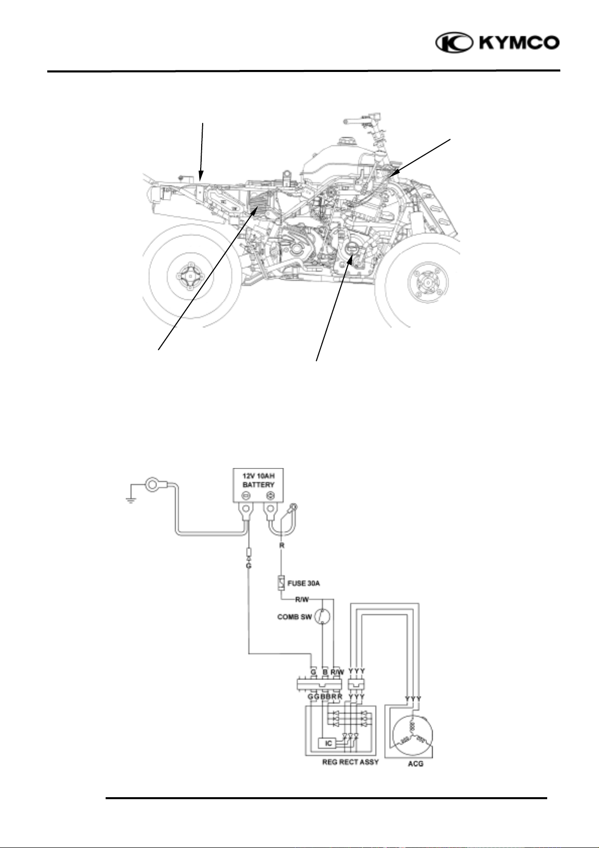
CHARGING CIRCUIT
Fuse/Battery
Regulator/Rectifier
A.C. Generator
Ignition Switch
Page 3
16. BATTERY/CHARGING SYSTEM/
A.C. GENERATOR
16-2
Mongoose/KXR 250
SERVICE INFORMATIONN
GENERAL INSTRUCTIONS
• The battery can be charged and discharged repeatedly. If a discharged battery is not used for a
long time, its service life will be shortened. Generally, the capacity of a battery will decrease after
it is used for 2_ 3 years. A capacity-decreased battery will resume its voltage after it is recharged
but its voltage decreases suddenly and then increases when a load is added.
• When a battery is overcharged, some symptoms can be found. If there is a short circuit inside the
battery, no voltage is produced on the battery terminals. If the rectifier won‘t operate, the
voltage will become too high and shorten the battery service life.
• If a battery is not used for a long time, it will discharge by itself and should be recharged every 3
months.
• A new battery filled with electrolyte will generate voltage within a certain time and it should be
recharged when the capacity is insufficient. Recharging a new battery will prolong its service life.
• Inspect the charging system according to the sequence specified in the Troubleshooting.
• Do not disconnect and soon reconnect the power of any electrical equipment because the electronic
parts in the regulator/rectifier will be damaged. Turn off the ignition switch before operation.
• It is not necessary to check the MF battery electrolyte or fill with distilled water.
• Check the load of the whole charging system.
• Do not quick charge the battery. Quick charging should only be done in an emergency.
• Remove the battery from the motorcycle for charging.
• When replacing the battery, do not use a traditional battery.
• When charging, check the voltage with an voltmeter.
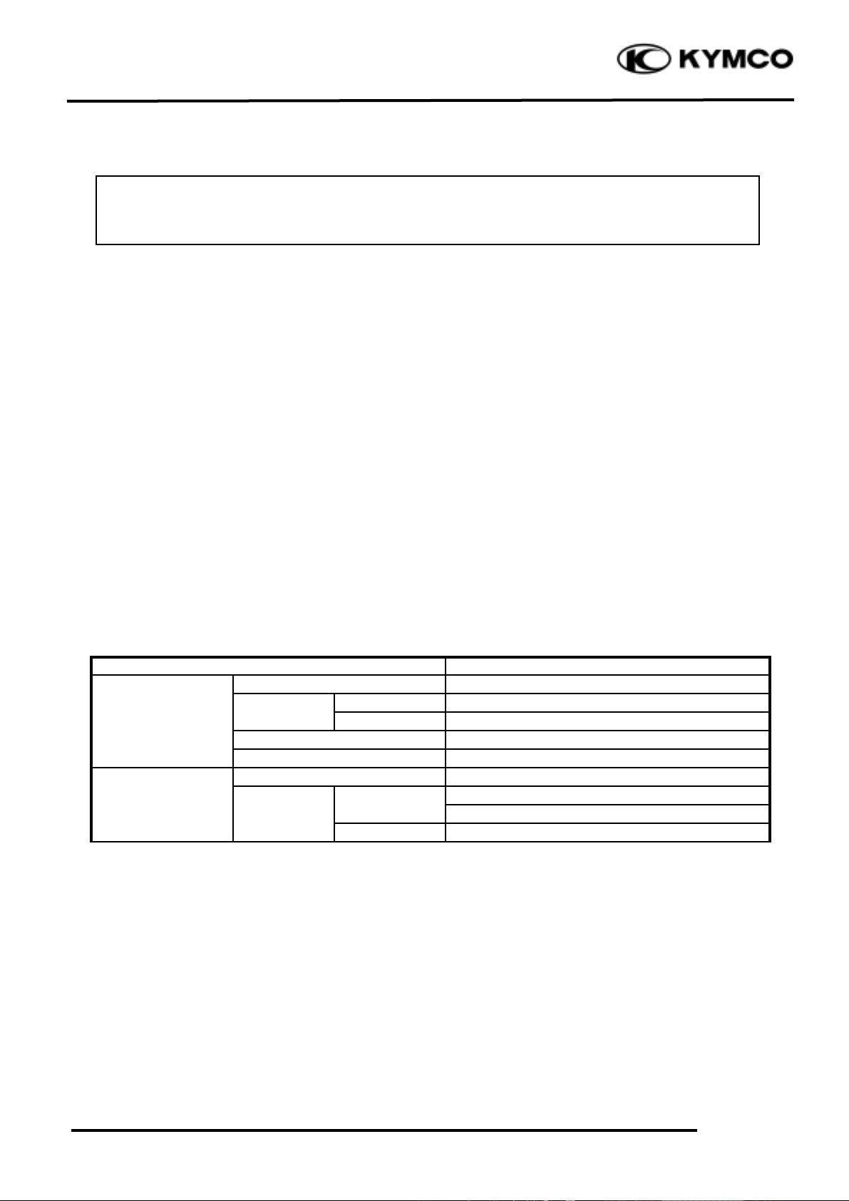
SPECIFICATIONS
Item
Standard
Capacity/Model
12V-12AH
Voltage
Fully charged
13.1V
Battery
(20¢J )
Undercharged
12.3V
Charging current
STD: 1.2A Quick: 3.0A
Charging time
STD: 5_ 10hr Quick: 30min
A.C. Generator
Capacity
150W
12.0_ 14.0V
Limit voltage
10_ 13.0V
Charging
13.5_ 15.5V
Lighting
Regulator/Rectifier
The battery electrolyte (sulfuric acid) is poisonous and may seriously damage the skin and
eyes. Avoid contact with skin, eyes, or clothing. In case of contact, flush with water and get
prompt medical attention
Page 4

16. BATTERY/CHARGING SYSTEM/
A.C. GENERATOR
16-3
Mongoose/KXR 250
TESTING INSTRUMENTS
Electric tester
TROUBLESHOOTING
No power Intermittent power
• Dead battery • Loose battery cable connection
• Disconnected battery cable • Loose charging system connection
• Fuse burned out • Loose connection or short circuit in
• Faulty ignition switch
lighting system
Low power Charging system failure
• Weak battery • Loose, broken or shorted wire or connector
• Loose battery connection • Faulty regulator/rectifier
• Charging system failure • Faulty A.C. generator
• Faulty regulator/rectifier
Page 5

16. BATTERY/CHARGING SYSTEM/
A.C. GENERATOR
16-4
Mongoose/KXR 250
BATTERY REMOVAL
Pull right the lock lever and pull up the seat
at the rear.
Remove the battery holder, by removing the
mount bolts. (Make sure the ignition switch
is oFF)
Remove the battery by removing the bolt.
First disconnect the battery negative (-)
cable and then the positive (+) cable.
The installation sequence is the reverse of
removal.
BATTERY VOLTAGE (OPEN CIRCUIT
VOLTAGE) INSPECTION
Remove the seat.
Disconnect the battery cables.
Measure the voltage between the battery
terminals.
Fully charged : 13.1V
Undercharged : 12.3V max
Lock Lever
Seat
When disconnecting the battery positive
(+) cable, do not touch the frame with
tool; otherwise it will cause short circuit
and sparks to fire the fuel.
Bolts
Battery Holder
Negative (-) Cable
Positive (+) Cable
First connect the positive (+) cable and then
negative (-) cable to avoid short circuit.
Battery charging inspection must be
performed with a voltmeter.
°Ø
Page 6

16. BATTERY/CHARGING SYSTEM/
A.C. GENERATOR
16-5
Mongoose/KXR 250
CHARGING
Connect the charger positive (+) cable to the
battery positive (+) terminal.
Connect the charger negative (-) cable to the
battery negative (-) terminal.
Charging current : Standard : 1.2A
Quick : 3.0A
Charging time : Standard : 5_ 10 hours
Quick : 30 minutes
After charging: Open circuit voltage: 12.8V min.
• Keep flames and sparks away
from a charging battery.
• Turn power ON/OFF at the
charger, not at the battery terminals to
prevent sparks near the battery to avoid
explosion.
• Charge the battery according to
• Quick charging should only be done in
an emergency.
• Measure the voltage 30 minutes after
the battery is charged.
°Ø
Page 7

16. BATTERY/CHARGING SYSTEM/
A.C. GENERATOR
16-6
Mongoose/KXR 250
CHARGING SYSTEM
SHORT CIRCUIT TEST
Disconnect the ground wire from the battery
and connect an ammeter across the battery
negative (-) terminal and the ground wire.
Turn the ignition switch OFF and check for
short circuit.
If any abnormality is found, check the ignition
switch and wire harness for short circuit.
CURRENT TEST
This inspection must be performed with an
electric tester when the battery is fully
charged.
Warm up the engine for inspection.
Connect the electric tester across the battery
terminals. Disconnect the red wire from the
fuse terminal and connect an ammeter
between the red wire lead and the fuse
terminal as shown.
Attach a tachometer to the engine.
Start the engine and gradually increase the
engine speed to measure the limit voltage
and current.
Limit Voltage/Current:
13.5_ 15.5V/0.5
A max.
If the limit voltage is not within the
specified range, check the regulator/rectifier.
Connect the electric tester positive (+)
terminal to ground wire and the tester
negative (-) terminal to the battery
negative (-) terminal.
°Ø
Page 8

16. BATTERY/CHARGING SYSTEM/
A.C. GENERATOR
16-7
Mongoose/KXR 250
REGULATOR/RECTIFIER
INSPECTION
Remove the front fender. (
Refer to chapter
2
)
Remove the regulator/rectifier wire coupler.
Check the continuity between the wire
terminals.
Normal Direction: Continuity
(+) Probe
(-) Probe
I
Yellow
Green
II
Red/White
Yellow
Reverse Direction: No Continuity
(+) Probe
(-) Probe
I
Green
Yellow
II
Yellow
Red/White
VOLTAGE REGULATION TEST
Connect a voltmeter across the battery
terminals.
Start the engine and gradually increase the
engine speed.
The battery terminal voltage should be
within 14.0_ 15.0V.
Regulator/Rectifier
Lock Nut
Regulator/Rectifier Couplers
Black
Green
Red/White
Normal
Direction
Reverse
Direction
Yellow
Page 9

16. BATTERY/CHARGING SYSTEM/
A.C. GENERATOR
16-8
Mongoose/KXR 250
A.C. GENERATOR INSPECTION
Disconnect the A.C. generator connector.
Check the continuity between the yellow
wires and ground.
There should be continuity between the
yellow wires and no continuity between
each yellow wire and ground.
Resistance (at 20°C):
Yellow_ Yellow
1.6_ 2.5W
A.C. GENERATOR/FLYWHEEL
REMOVAL
Remove the right crankcase cover. (Refer to
the “WATER PUMP SHAFT
REMOVAL” section in the chapter 12)
Remove the pulser coil screws and then
remove the A.C. generator wire set plate.
Remove the A.C. generator bolts and then
remove A.C. generator and pulser coil from
right crankcase cover.
Remove the oil through guide and spring.
Hold the flywheel with a flywheel holder
and remove flywheel nut and wash.
Flywheel holder E021
Bolts
Screws
Set Plate
Pulser Coil
A.C. Generator
Spring
Oil Through Guide
Nut
Flywheel
Flywheel Holder
This test can be made without removing
the stator from the engine.
°Ø
When removing the pulser coil and
stator, be careful not to damage them to
avoid shorted or broken wire.
°Ø
Special
Page 10

16. BATTERY/CHARGING SYSTEM/
A.C. GENERATOR
16-9
Mongoose/KXR 250
Remove the flywheel with a flywheel puller.
Flywheel puller E003
INSTALLATION
Reverse the “REMOVAL” procedures.
Install the flywheel, washer and tighten the
nut.
Torque: 5.5_ 6.5kgf-m
Install the oil through guide and spring.
Install the A.C. generator onto the right
crankcase cover and tighten the bolts.
Torque: 0.8_ 1.0kgf-m
Install the right crankcase cover.
Special
Flywheel Puller
_Before installation, check and make sure
that the inside of the flywheel is not
contaminated.
_Make sure install the flywheel onto the
crankshaft by aligning the key on the
crankshaft with the groove in the
flywheel.
°Ø
Key
Groove
Washer
 Loading...