

Page 1

15. REAR WHEEL/AXLE/SUSPENSION
15-0
Mongoose/KXR 250
15
__________________________________________________________________________________
__________________________________________________________________________________
__________________________________________________________________________________
__________________________________________________________________________________
__________________________________________________________________________________
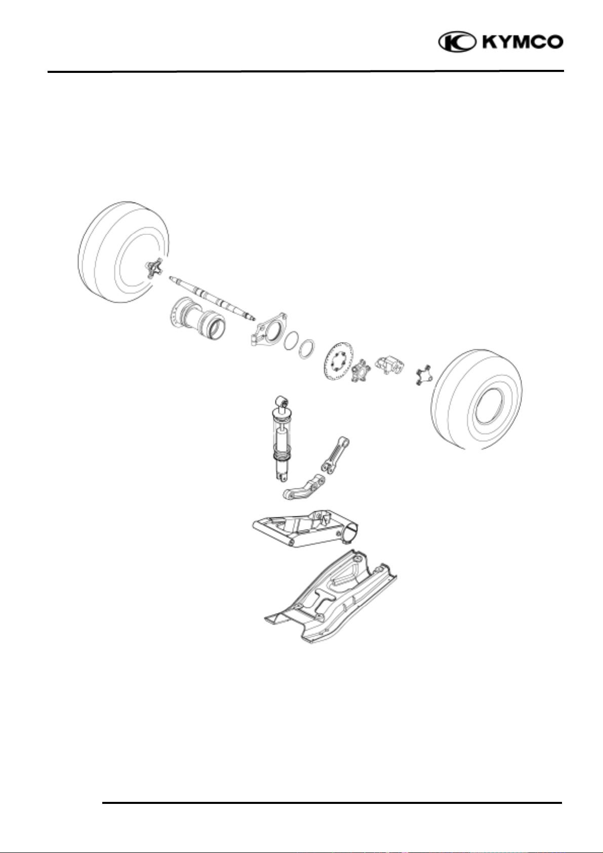
REAR WHEEL/AXLE/SUSPENSION
__________________________________________________________________________________
SERVICE INFORMATION -------------------------------------------- 15- 2
TROUBLESHOOTING ------------------------------------------------- 15- 3
REAR WHEEL/AXLE/AXLE HUB ----------------------------------- 15- 3
REAR FORK/SWIM ARM/SHOCK ABSORBER -------------------- 15- 12
15
Page 2
15. REAR WHEEL/AXLE/SUSPENSION
15-1
Mongoose/KXR 250
Page 3
15. REAR WHEEL/AXLE/SUSPENSION
15-2
Mongoose/KXR 250
SERVICE INFORMATION
GENERAL INSTRUCTIONS
• Jack the machine front wheel off the ground and be careful to prevent the machine from falling
down.
• During servicing, keep oil or grease off the brake disk
• Inspect the brake system before riding.
SPECIFICATIONS
Item
Standard (mm)
Service Limit (mm)
Radialæ2.0
Axialæ2.0
TORQUE VALUES
Rear wheel nut 5.0_ 6.0kgf-m
Rear shock absorber upper mount bolt 3.5_ 4.5kgf-m
Rear shock absorber lower mount bolt 3.5_ 4.5kgf-m
Rear fork axle 6.0_ 8.0kgf-m
Rear wheel hub nut 6.0_ 8.0kgf-m
Rear wheel shaft nut 11.0_ 13.0kgf-m
Caliper holder bolt 1.8_ 2.5kgf-m
SPECIAL TOOLS
Nut wrench F010
TROUBLESHOOTING
Rear wheel wobbling
• Bent rim
• Faulty tire
• Axle not tightened properly
Soft rear shock absorber
• Weak shock absorber spring
• Faulty damper
Rim run out
Rear wheel
Page 4
15. REAR WHEEL/AXLE/SUSPENSION
15-3
Mongoose/KXR 250
REAR WHEEL/AXLE/AXLE HUB
REMOVAL AND INSPECTION
Place the machine on a level place.
Remove the rear caliper. (Refer to the
“REAR BRAKE CALIPER
REMOVAL” section in chapter 13)
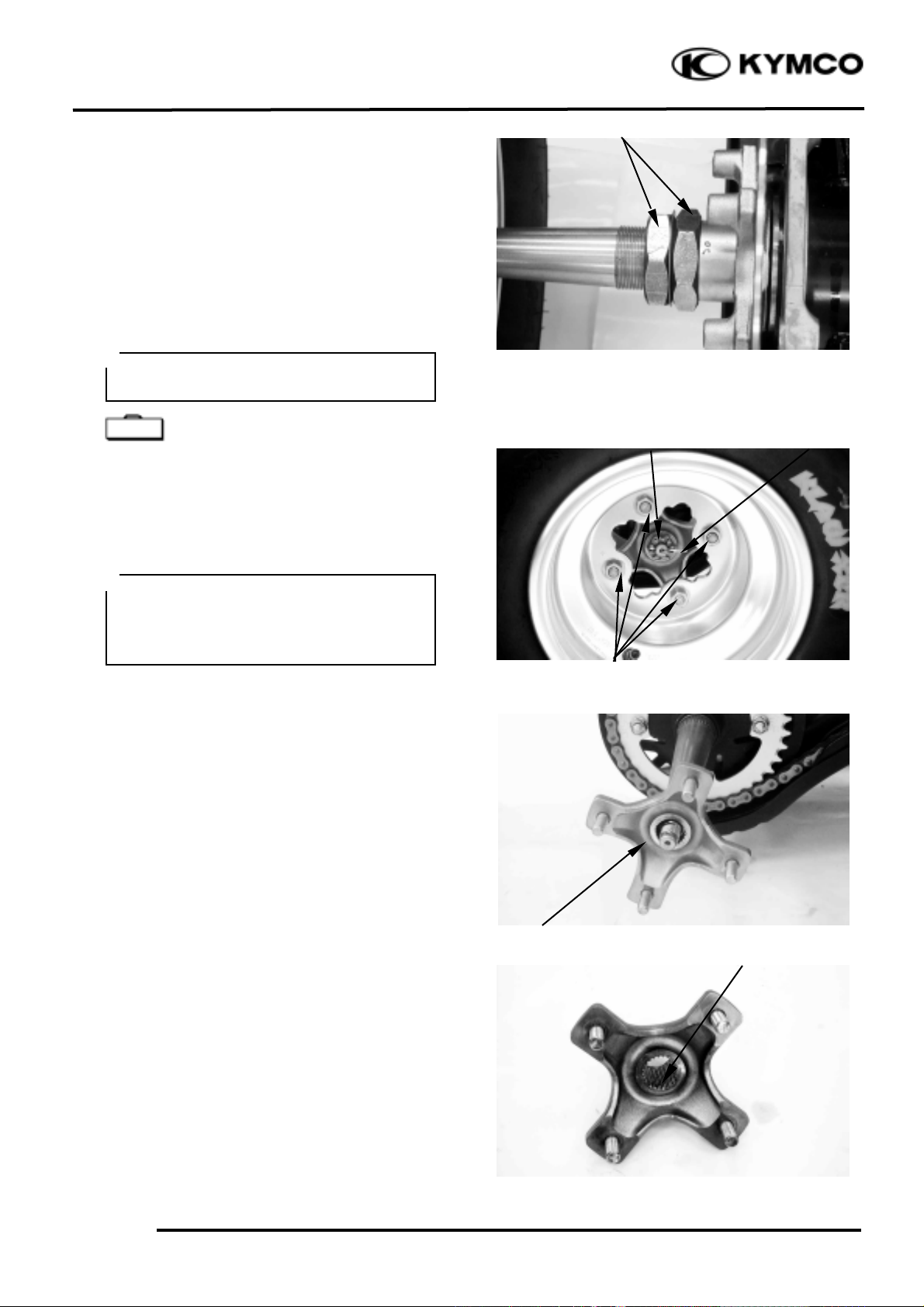
Use the nut wrench to loosen two rear axle
nuts (inner and outer) of the rear axle.
Nut wrench F010
Remove four nuts attaching the rear wheel
hub of the both rear wheels, then remove the
both rear wheels.
Remove the cotter pin and then remove nut.
Remove the rear wheel hub.
Inspect the rear wheel hub.
Cracks/damage _ Replace.
Inspect the rear wheel hub splines.
Wear/damage _ Replace.
Elevate the rear wheels by placing a
suitable stand under the rear of frame.
Support the machine securely so there is
no danger of it falling over.
°Ø
Special
Note that the rear axle nuts are left
threaded.
°Ø
Rear Axle Nuts
Wheel Nuts
Cotter Pin
RearWheel Hub Nut
Rear Wheel Hub
Splines
Page 5
15. REAR WHEEL/AXLE/SUSPENSION
15-4
Mongoose/KXR 250
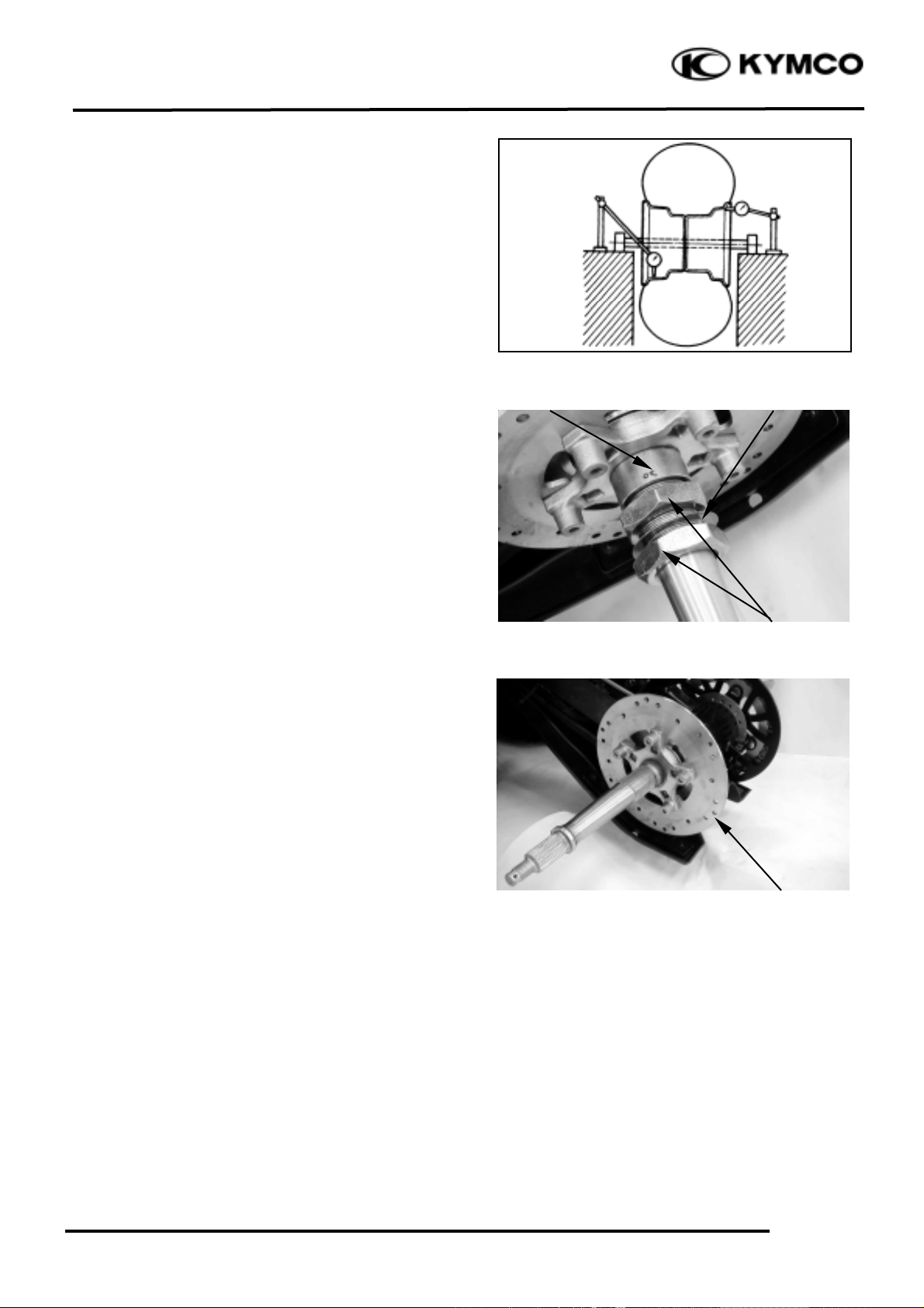
Measure the wheel runout.
Service Limit:
Vertical: 2.0 mm
Lateral: 2.0mm
Out of specification _ Replace wheel.
Remove the two rear axle nuts (outer and
inner), washer and collar.
Remove the rear brake disk.
Rear Axle Nuts
Washer
Collar
Rear Brake Disk
Page 6
15. REAR WHEEL/AXLE/SUSPENSION
15-5
Mongoose/KXR 250
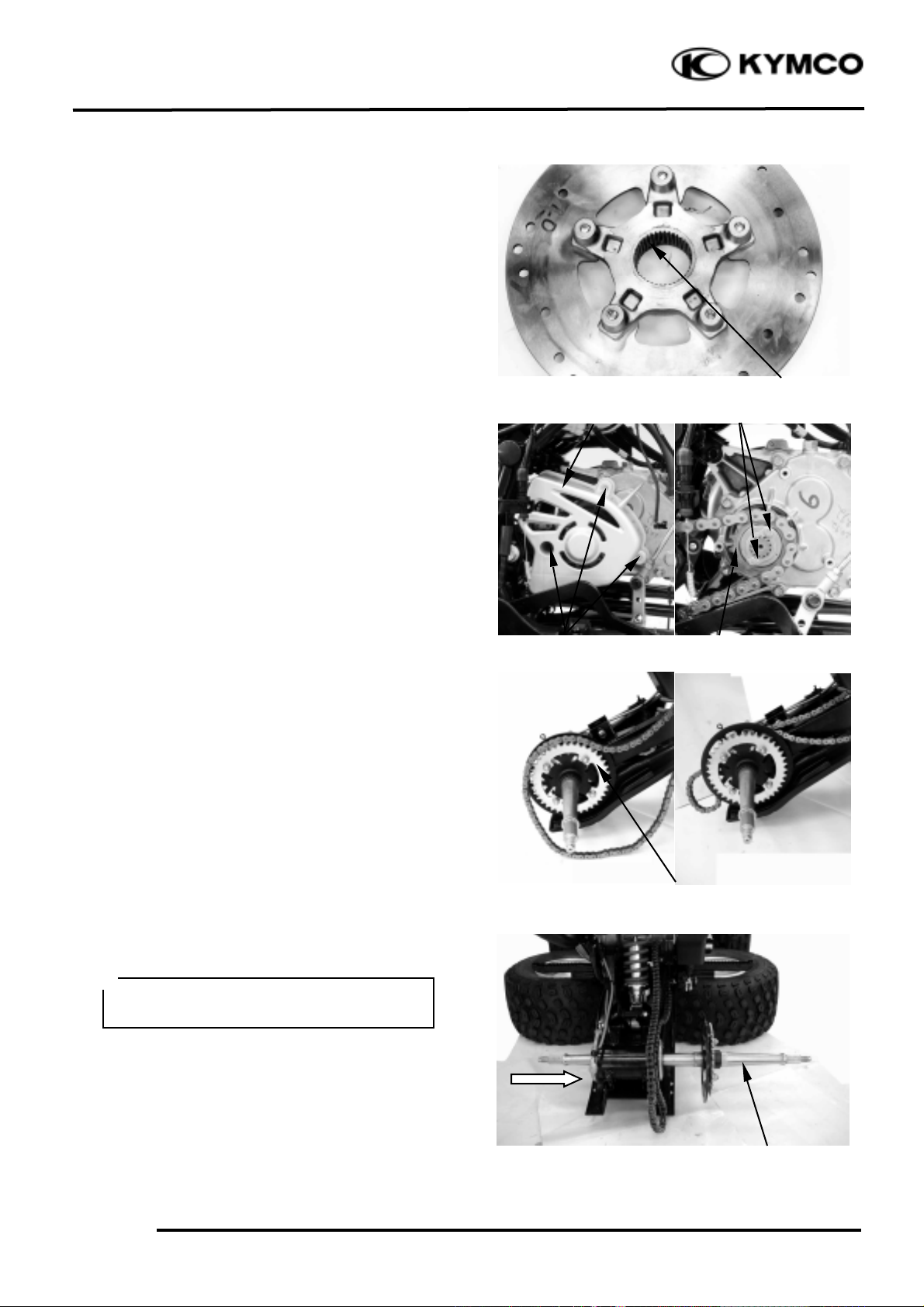
Inspect the brake disk
Cracks/damage _ Replace.
Inspect the brake disk splines.
Wear/damage _ Replace.
Loosen the driven chain (refer to the
“DRIVE CHAIN SLACK
ADJUSTMENT” section in the chapter 3)
and remove the two bolts at the drive
sprocket (refer to the chapter 6), then
disconnect the drive chain from the driven
sprocket.
Remove the rear axle from right side.
Driven Sprocket
Rear Axle
Splines
Tap the axle and with a rubber hammer,
this will avoid damage the axle thread.
°Ø
Bolts
Drive Sprocket Cover
Bolts
Drive Sprocket
Page 7

15. REAR WHEEL/AXLE/SUSPENSION
15-6
Mongoose/KXR 250
REAR AXLE DISASSEMBLY
Remove the driven sprocket clip at the rear
axle and then remove the driven sprocket.
Remove the four nuts attaching the driven
sprocket holder at the driven sprocket and
then remove driven sprocket.
Inspect the drive sprocket and driven
sprocket.
More than 1/4 teeth wear _ Replace.
Bent teeth _ Replace.
Clip
Nuts
Page 8

15. REAR WHEEL/AXLE/SUSPENSION
15-7
Mongoose/KXR 250
Inspect the driven sprocket holder splines.
Wear/damage _ Replace.
Inspect the rear axle.
Scratched (excessively)/damage _ Replace.
Inspect the splines and threads of the rear
axle
Wear/damage _ Replace.
Measure the rear axle run out.
Service limit: less than 1.5mm
Out of specification _ Replace.
REAR AXLE ASSEMBLY
Reverse the “REAR AXLE
DISASSEMBLY” procedures.
Remove the bolt at the rear caliper holder.
Remove the two bolts attaching the rear axle
hub at the rear fork.
Do not attempt to straighten a bent axle.
°Ø
Apply grease onto the rear axle splines.
°Ø
Splines
Bolt
Bolts
Page 9

15. REAR WHEEL/AXLE/SUSPENSION
15-8
Mongoose/KXR 250
Remove the circlip at the caliper holder and
then remove the caliper holder and collar.
Remove the rear axle hub from right side.
Circlip
Collar
Caliper Holder
Rear Axle Hub
Page 10

15. REAR WHEEL/AXLE/SUSPENSION
15-9
Mongoose/KXR 250
Inspect rear axle hub.
Bearings allow play in the axle hub or the
bearing turns roughly _ Replace.
Oil seals is wear/damage _ Replace.
Axle hub is cracks/bend/damage _
Replace.
REAR AXLE HUB DISASSEMBLY
Bearing and dust seal replacement steps:
Clean the outside of the rear axle hub.
Remove the dust seal by a flat-head screw
driver.
Remove the bearing by a general bearing
puller.
REAR AXLE HUB ASSEMBLY
Install the new bearing and dust seal by
reversing the previous steps.
Place a wood block against the outer
edge to protect this edge.
°Ø
Do not strike the center race or balls of
the bearing.
Contact should be made only with the
outer race.
Make sure install the distance collar into
the rear axle hub
°Ø
Dust Seal
Dust Seal
Dust Seal
Bearing
Rear Axle Hub
Distance Collar
Page 11

15. REAR WHEEL/AXLE/SUSPENSION
15-10
Mongoose/KXR 250
INSTALLATION
Reverse the “REAR WHEEL/AXLE/AXLE
HUB REMOVAL AND INSPECTION”
procedures.
Install the rear axle hub.
Install the rear axle.
Connect the drive chain.
Install the rear brake disk, collar inner nut,
washer and outer nut.
Install the rear wheel hub and tighten the
nut.
Torque: 6.0_ 8.0kgf-m
Install cotter pin (new)
Apply grease onto the dust seal lips and
bearings.
°Ø
At this time, the rear axle hub should not
be tightened completely.
Final tightening is done after the chain
slack adjustment.
°Ø
At this time, the nuts should not
be tightened completely.
°Ø
Do not loosen the axle nut after torque
tightening. If the axle nut groove id not
aligned with the cotter pin hole, align
groove with the hole by tightening ut on
the axle nut.
Always use a new cotter pin.
°Ø
Page 12

15. REAR WHEEL/AXLE/SUSPENSION
15-11
Mongoose/KXR 250
Install the rear wheel and tighten the four
nuts.
Torque: 5.0_ 6.0kgf-m
Tighten the two rear axle nuts (inner and
outer).
Nut wrench F010
Torque: 11.0_ 13.0kgf-m
Adjust drive chain slack. (Refer to the
“DRIVE CHAIN SLACK
ADJUSTMENT” section in the CHAPTER
3.)
Approximately: 30 mm
Be sure the tapered side of the wheel
nuts face the wheel rim.
°Ø
Special
Note that the rear axle nuts are left
threaded.
°Ø
Page 13

15. REAR WHEEL/AXLE/SUSPENSION
15-12
Mongoose/KXR 250
REAR FORK/SWIM
ARM/SHOCK ABSORBER
REMOVAL AND INSPECTION
Place the machine on a level place.
Elevate the rear wheels by placing a suitable
stand under the rear of frame.
Remove the rear wheels, rear axle and rear
hub.
Refer to the “REAR WHEEL/AXLE/AXLE
HUB REMOVAL AND INSPECTION”
section in chapter 15.
Remove the two bolts at the air cleaner case.
(Refer to the “CARBURETOR
REMOVAL” section in chapter 5.)
Elevate the air cleaner case and remove the
upper mount bolt at the rear shock absorber
Remove the four bolts at the lower guard
and then remove the lower guard.
Remove the lower mount bolt at the rear
shock absorber and then remove the shock
absorber and bush.
Bolt
Air Cleaner Case
Bolts
Lower Guard
Lower Bolt
Support the machine securely so there is
no danger of it falling over.
°Ø
When removing the lower guard, hold the
swing arm so that it does not drop
downwards when the lower guard is
removed.
°Ø
Page 14

15. REAR WHEEL/AXLE/SUSPENSION
15-13
Mongoose/KXR 250
Remove the two bolts attaching the rear
swing arm at the rear fork and then remove
the rear swing arm.
Inspect the shock absorber rod.
Bends/damage _ Replace the shock absorber
assembly.
Inspect the shock absorber.
Oil leaks _ Replace the shock absorber
assembly.
Inspect the spring.
Fatigue _ Replace the shock absorber
assembly.
Move the spring up and down.
Inspect the bush.
Wear/damage _ Replace.
REAR SWING ARM DISASSEMBLY
Remove the bolt attaching the lower rear
swing arm at the upper rear swing arm and
then disconnect the upper rear swing arm
from the lower rear swing arm.
Inspect the upper rear swing arm.
Bends/damage _ Replace.
Inspect the bush.
Wear/damage _ Replace.
Bolts
Rear Swim Arm
Bush
Shock Absorber
Bolt
Bush
Upper Rear Swing Arm
Lower Rear Swing Arm
Page 15

15. REAR WHEEL/AXLE/SUSPENSION
15-14
Mongoose/KXR 250
Remove the dust seals and the bushes from
the lower rear swing arm.
Inspect the lower rear swing arm.
Wear/damage _ Replace.
Inspect the bush.
Wear/damage _ Replace.
Inspect the needle bearings.
Bring allow play in the lower rear swing arm
or bearing turns roughly _ Replace.
REAR SWING ARM ASSEMBLY
Reverse the “REAR SWING ARM
DISASSEMBLY” procedures.
Install the upper rear swing arm and tighten
the bolt.
Torque: 3.5_ 4.5kgf-m
Check the tightening torque of the pivot
shaft (rear fork) securing nut.
Torque: 6.0_ 8.0kgf-m
Check the rear fork side play by moving it
from side to side.
If side play noticeable, check the inner
collar, bearing, bushing and thrust cover, or
adjust the shim.
Apply grease onto the oil seal lips,
needle bearing and bushes.
°Ø
Bushes
Bush
Dust Seals
Dust Seals
Dust Seal
Lower Rear Swing Arm
Needle Bearing
Pivot Shaft
Page 16

15. REAR WHEEL/AXLE/SUSPENSION
15-15
Mongoose/KXR 250
Check the rear fork vertical movement by
moving it up and down.
If vertical movement is tight, binding or
rough, check the inner collar, bearing,
bushing and thrust cover, or adjust the shim.
Remove the band and then disconnect the
rear brake fluid tubes from the rear fork.
Remove the nut and pivot shaft, then
remove rear fork and drive chain.
Remove the thrust covers.
Band
Rear Fluid Tube
Pivot Shaft
Swing Arm
Thrust Covers
Page 17

15. REAR WHEEL/AXLE/SUSPENSION
15-16
Mongoose/KXR 250
Inspect the rear fork.
Crack/bend/damage _ Replace.
Roll the axle on a flat surface to inspect the
pivot shaft.
Bends _ Replace.
Inspect the thrust covers, collar and bushes.
Wear/damage _ Replace.
Inspect the drive chain stiffness.
Stiff _Clean and lubricate or replace.
Do not attempt to straighten a bent axle.
°Ø
Thrust Covers
Collar
Page 18

15. REAR WHEEL/AXLE/SUSPENSION
15-17
Mongoose/KXR 250
INSTALLATION
Reverse the “REAR FORK/SWIM
ARM/SHOCK ABSORBER
REMOVAL AND INSPECTION”
procedure.
Apply grease onto the collar, bush, pivot
shaft and thrust cover.
Install the rear fork and tightening the nut
and pivot shaft.
Torque: 6.0_ 8.0kgf-m
Install the rear swing arm and tightening the
bolts.
Torque: 3.5_ 4.5kgf-m
Install the shock absorber and tightening the
bolts.
Torque: 3.5_ 4.5kgf-m
Install the rear hub and rear wheels.
Refer to the “REAR WHEEL
INSTALLATION” section.
Adjust the drive chain slack.
Refer to the “DRIVE CHAIN SLACK
ADJUSTMENT” section in the CHAPTER
3.
Approximately: 30 mm
 Loading...