

Kymco MO GD 250 Service Manual - chap14 (ruota sospensioni ant)

14.STEERING HANDLEBAR/FRONT WHEEL/FRONT
BRAKE/FRONT SHOCK ABSORBER/FRONT FORK
14-0
GRAND DINK 250
14
__________________________________________________________________________________
__________________________________________________________________________________
__________________________________________________________________________________
__________________________________________________________________________________
__________________________________________________________________________________
STEERING HANDLEBAR/FRONT WHEEL/FRONT
BRAKE/FRONT SHOCK ABSORBER/FRONT FORK
__________________________________________________________________________________
SCHEMATIC DRAWING ---------------------------------------------- 14- 1
SERVICE INFORMATION -------------------------------------------- 14- 2
TROUBLESHOOTING ------------------------------------------------- 14- 3
STEERING HANDLEBAR--------------------------------------------- 14- 4
FRONT WHEEL--------------------------------------------------------- 14- 5
FRONT BRAKE --------------------------------------------------------- 14- 8
FRONT SHOCK ABSORBER------------------------------------------ 14-14
FRONT FORK ----------------------------------------------------------- 14-17
14
14.STEERING HANDLEBAR/FRONT WHEEL/FRONT
BRAKE/FRONT SHOCK ABSORBER/FRONT FORK
14-1
GRAND DINK 250
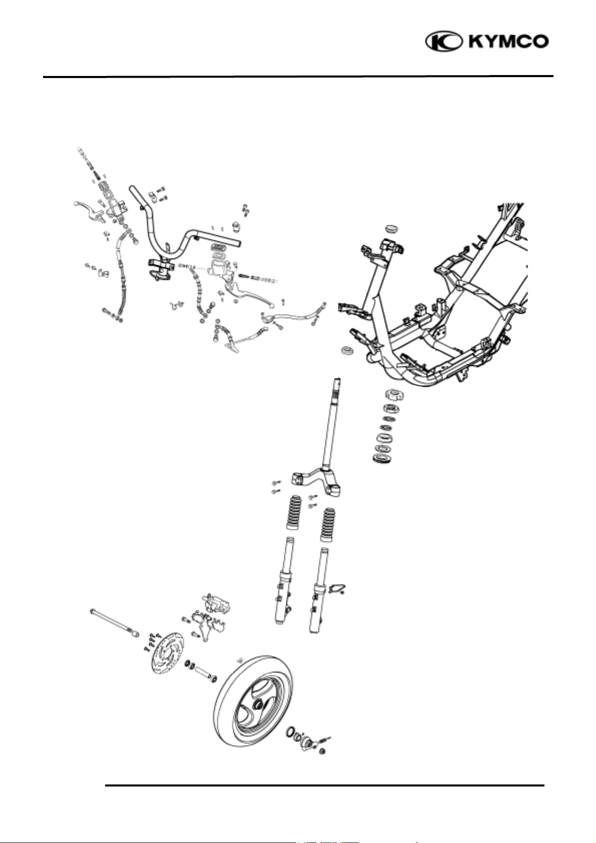
SCHEMATIC DRAWING
14.STEERING HANDLEBAR/FRONT WHEEL/FRONT
BRAKE/FRONT SHOCK ABSORBER/FRONT FORK
14-2
GRAND DINK 250
SERVICE INFORMATION
GENERAL INSTRUCTIONS
• Remove the motorcycle frame covers before removing the front wheel, steering handlebar, front
shock absorber and front fork. Jack the motorcycle front wheel off the ground and be careful to
prevent the motorcycle from falling down.
• During servicing, keep oil or grease off the brake pads and brake disk.
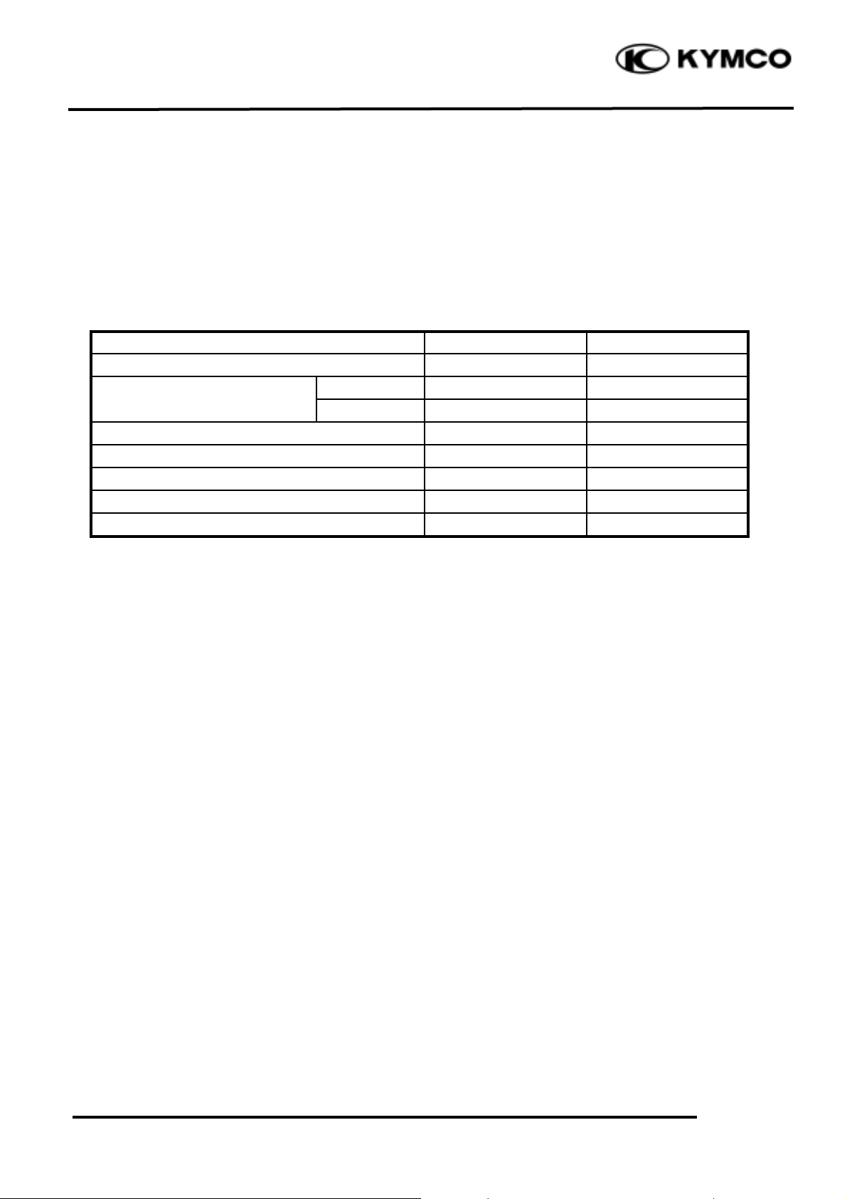
SPECIFICATIONS
Item
Standard (mm)
Service Limit (mm)
Axle shaft runout
æ
0.2
Radialæ2.0
Front wheel rim runout
Axialæ2.0
Front shock absorber spring free length
240.6
233
Brake disk thickness
3.8_ 4.2
3.0
Brake disk runout
æ
0.30
Brake master cylinder I.D.
12.70_ 12.74
12.75
Brake master cylinder piston O.D.
12.65_ 12.68
12.64
TORQUE VALUES
Steering stem lock nut 78.4_ 117.6N-m
Steering top cone race 4.9_ 12.7N-m
Front shock absorber bolt 19.8_ 24.5N-m
Front axle nut 44.1_ 49N-m
Brake caliper bolt 24.5N_ 34.3N-m
SPECIAL TOOLS
Lock nut wrench
Front shock absorber compressor
Ball race remover
Driver handle
Outer driver, 37x40mm
Pilot, 12mm
Bearing remover
Bearing remover head, 12mm

14.STEERING HANDLEBAR/FRONT WHEEL/FRONT
BRAKE/FRONT SHOCK ABSORBER/FRONT FORK
14-3
GRAND DINK 250
TROUBLESHOOTING
Hard steering (heavy) Front wheel wobbling
• Excessively tightened steering stem top • Bent rim
cone race • Loose front axle
• Broken steering balls • Bent spoke plate
• Insufficient tire pressure • Faulty tire
Steers to one side or does not track straight • Improperly tightened axle nut
• Uneven front shock absorbers Soft front shock absorber
• Bent front fork • Weak shock springs
• Bent front axle or uneven tire • Insufficient damper oil
Poor brake performance Front shock absorber noise
• Worn brake pads • Slider bending
• Contaminated brake pad surface • Loose fork fasteners
• Deformed brake disk • Lack of lubrication
• Air in brake system
• Deteriorated brake fluid
• Worn brake master cylinder piston oil seal
• Clogged brake fluid line
• Unevenly worn brake caliper
14.STEERING HANDLEBAR/FRONT WHEEL/FRONT
BRAKE/FRONT SHOCK ABSORBER/FRONT FORK
14-4
GRAND DINK 250
STEERING HANDLEBAR
REMOVAL
Remove the handlebar front and rear covers.
(!2-6)
Remove the front and rear brake master
cylinder attaching bolts.
Remove the front upper cover. (!2-5)
Remove the front lower cover. (!2-5)
Remove the floor board. (!2-4)
Remove the leg shield. (!2-5)
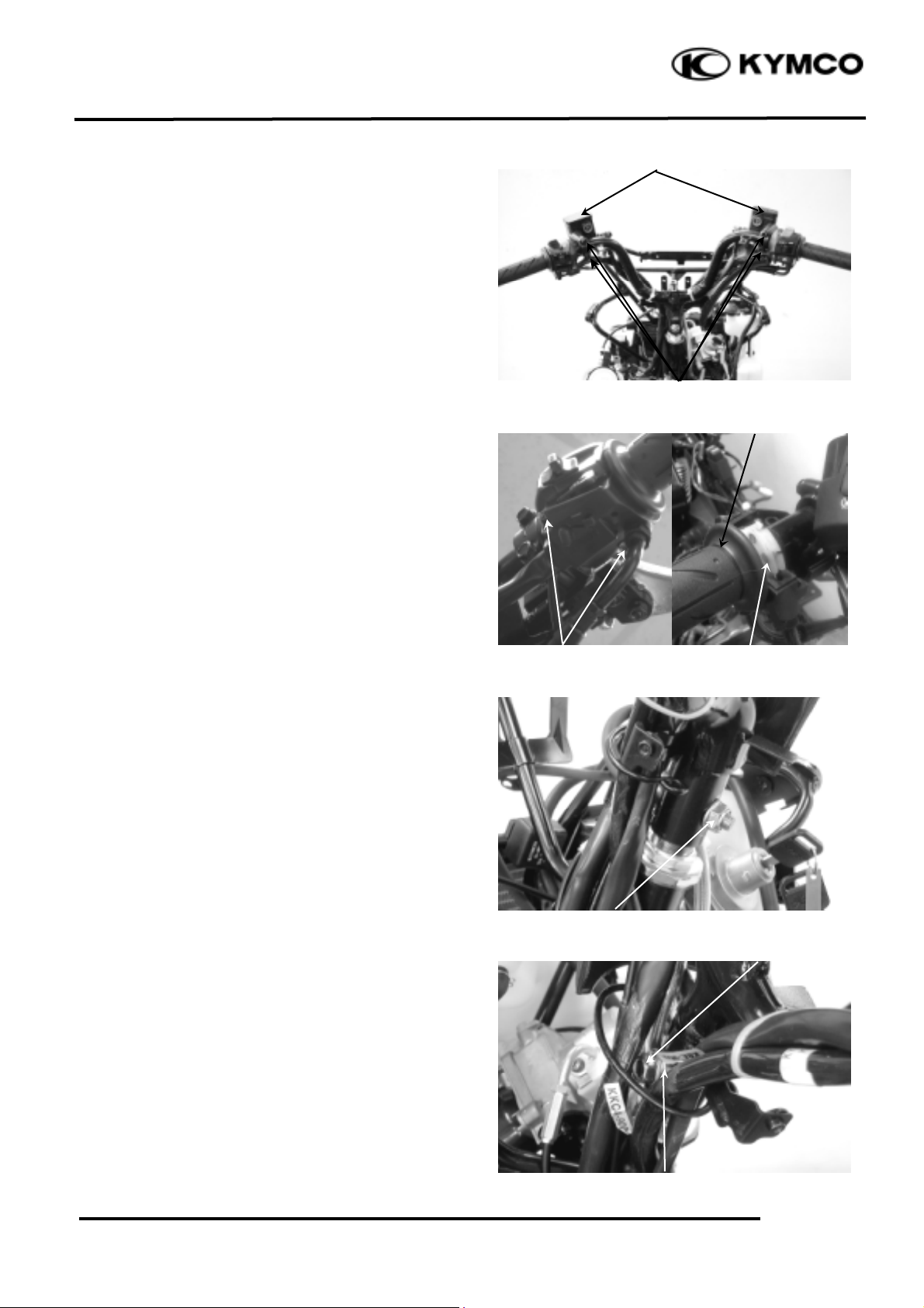
Remove the four screws attaching the right
and left handlebar switches.
Disconnect the throttle cable from the throttle
grip and remove the throttle grip from the
handlebar.
Remove the handlebar lock nut and take out
the bolt.
Remove the handlebar.
INSTALLATION
Install the handlebar onto the steering stem
and install the handlebar collar, lock nut and
bolt.
Tighten the bolt to the specified torque.
Torque: 39.2_ 49N-m
Brake Master Cylinders
Screws
Bolts
Collar
Throttle Grip
Throttle Cable
Bolt
Lock Nut
14.STEERING HANDLEBAR/FRONT WHEEL/FRONT
BRAKE/FRONT SHOCK ABSORBER/FRONT FORK
14-5
GRAND DINK 250
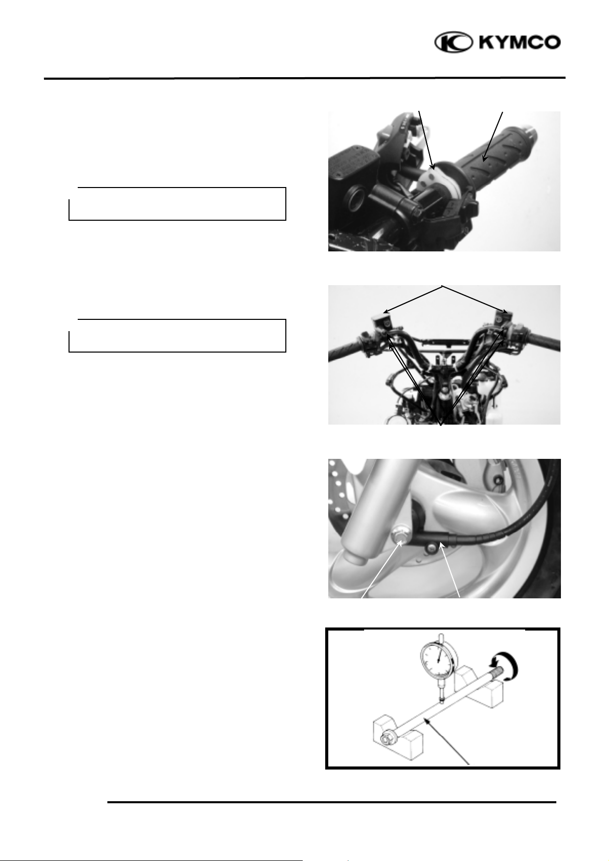
Lubricate the throttle grip front end with
grease and then install the throttle grip.
Connect the throttle cable to the throttle grip.
Install the right and left handlebar switches
and tighten the screws.
Install the front and rear brake master
cylinders.
FRONT WHEEL
REMOVAL
Jack the motorcycle front wheel off the
ground.
Remove the front axle nut to pull out the axle.
Remove the front wheel and the speedometer
gear unit.
INSPECTION
AXLE RUNOUT
Set the axle in V blocks and measure the
runout using a dial gauge.
The actual runout is _ of the total indicator
reading.
Service Limit: 0.2mm replace if over
Bolt
Throttle Grip
Throttle Cable
• Adjust the throttle grip free play to the
specified range of 2_ 6mm.
*
• Install the brake master cylinders by
aligning the index marks.
*
Brake Master Cylinder
Axle Nut
Speedometer Gear Unit
 Loading...