

Page 1

2. EXHAUST MUFFLER/FRAME COVERS
2-0
GRAND DINK 250
2
__________________________________________________________________________________
__________________________________________________________________________________
__________________________________________________________________________________
__________________________________________________________________________________
__________________________________________________________________________________
EXHAUST MUFFLER/FRAME COVERS
__________________________________________________________________________________
SCHEMATIC DRAWING ---------------------------------------------- 2-1
SERVICE INFORMATION -------------------------------------------- 2-2
TROUBLESHOOTING ------------------------------------------------- 2-2
FRAME COVERS REMOVAL----------------------------------------- 2-3
EXHAUST MUFFLER REMOVAL ----------------------------------- 2-6
2
Page 2
2. EXHAUST MUFFLER/FRAME COVERS
2-1
GRAND DINK 250
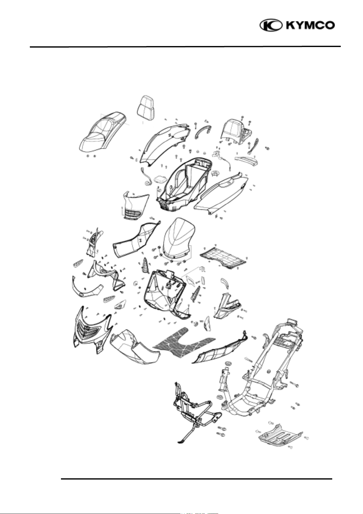
SCHEMATIC DRAWING
Page 3

2. EXHAUST MUFFLER/FRAME COVERS
2-2
GRAND DINK 250
SERVICE INFORMATION
GENERAL INSTRUCTIONS
• When removing frame covers, use care not to pull them by force because the cover joint claws
may be damaged.
• Make sure to route cables and harnesses according to the Cable & Harness Routing.
TORQUE VALUES
Exhaust muffler lock bolt 34.3N-m
Exhaust muffler joint lock nut 11.8N-m
TROUBLESHOOTING
Noisy exhaust muffler
• Damaged exhaust muffler
• Exhaust muffler joint air leaks
Lack of power
• Caved exhaust muffler
• Clogged exhaust muffler
• Exhaust muffler air leaks
Page 4

2. EXHAUST MUFFLER/FRAME COVERS
2-3
GRAND DINK 250
FRAME COVERS REMOVAL
REAR CARRIER & HAND RAIL
REMOVAL
Remove the met-in box:
First remove the three bolts and two nuts
attaching the met-in box.
Remove the met-in box.
Remove the hand rail right and left lock hex
bolts.
Remove the two hex bolts
Remove the rear carrier and hand rail.
FRAME BODY COVER REMOVAL
Remove the two screws on the center cover.
Remove the center cover.
Remove the three bolts on the back fender.
Remove the back fender.
Nuts
Bolts
Bolt
Bolts
Center Cover
Screws
Bolts
Page 5

2. EXHAUST MUFFLER/FRAME COVERS
2-4
GRAND DINK 250
Remove the two screws on the molding
covers.
Remove the molding covers.
Remove the two nuts and one bolt on the
back taillight.
Remove the left and right sides screws on the
frame body cover.
Remove the frame body cover.
FLOOR BOARD REMOVAL
Remove the blot on the front right and left
side covers.
Screws
Molding Cover
Nuts
Screws
Bolt
Side Cover
Blot
Page 6

2. EXHAUST MUFFLER/FRAME COVERS
2-5
GRAND DINK 250
Remove the left and right side screws on the
side cover.
Remove the side cover.
Remove the four bolts on the floor board.
Remove the floor board.
FRONT UPPER COVER REMOVAL
Remove the two screws on the front upper
cover.
Remove the front upper cover.
Remove the four bolts on the front windshield.
Remove the front windshield.
Bolts
Screws
Screws
Bolts
Bolt
Page 7

2. EXHAUST MUFFLER/FRAME COVERS
2-6
GRAND DINK 250
FRONT COVER REMOVAL
First remove the front upper cover.
Remove the two bolts attaching the front
cover.
Remove the six screws on the back of the
front cover.
Disconnect the right/left turn signal light wire
connectors.
Remove the front cover
The installation sequence is the reverse of
removal.
Remove the six screws on the front lower
cover.
Remove the front lower cover.
BACK COVER REMOVAL
Remove the front cover.
Remove the key moldings.
Remove the fuel cap moldings.
Remove the back cover bolt.
Remove the back cover.
Bolts
Key Moldings
Screws
Fuel Cap Moldings
Screws
Bolts
Page 8

2. EXHAUST MUFFLER/FRAME COVERS
2-7
GRAND DINK 250
Remove the three screws attaching fuel tank
inlet tube join.
Remove the back cover.
BOTTOM COVER REMOVAL
Remove the side stand.
Remove the four bolts attaching the bottom
cover.
Remove the bottom cover.
FRONT FENDER REMOVAL
Remove the two bolts attaching the fender.
Remove the front fender cover.
The installation sequence is the reverse of
removal.
EXHAUST MUFFLER REMOVAL
Remove the two exhaust muffler joint lock
nuts.
Remove the three exhaust muffler lock bolts
to remove the exhaust muffler.
Remove the exhaust muffler joint packing
collar.
The installation sequence is the reverse of
removal.
Torque:
Exhaust muffler joint lock nut:11.8N-m
Exhaust muffler lock bolt: 34.3N-m
Screws
Fuel Tank Inlet Tube
Bolts
Bottom Cover
Side Stand
Bolts
Lock Bolts
Page 9

2. EXHAUST MUFFLER/FRAME COVERS
2-8
GRAND DINK 250
HANDLEBAR COVER REMOVAL
First remove the three screws attaching the
handlebar under cover.
Remove the handlebar under cover.
Remove the screw from the handlebar upper
cover.
Remove the screw from the bottom of
handlebar upper cover.
Remove the handlebar upper cover.
Screws
Screw
Screw
 Loading...