

Page 1

13. FUEL SYSTEM/CARBURETOR/
FUEL PUMP/ FUEL TANK
13-0
GRAND D INK 25 0
13
__________________________________________________________________________________
__________________________________________________________________________________
__________________________________________________________________________________
__________________________________________________________________________________
__________________________________________________________________________________
FUEL SYSTEM/CARBURETOR/FUEL PUMP
__________________________________________________________________________________
FUEL SYSTEM --------------------------------------------------------- 13- 1
SCHEMATIC DRAWING ---------------------------------------------- 13- 2
OPERATION OF CARBURETOR JETS------------------------------ 13- 3
SERVICE INFORMATION -------------------------------------------- 13- 5
CARBURETOR REMOVAL ------------------------------------------- 13- 7
VACUUM CHAMBER DISASSEMBLY------------------------------ 13- 7
FLOAT CHAMBER DISASSEMBLY--------------------------------- 13- 9
AUTO BYSTARTER INSPECTION/REMOVAL-------------------- 13-11
AIR CUT-OFF VALVE (A.C.V.)-------------------------------------- 13-12
AUTO BYSTARTER INSTALLATION ------------------------------ 13-14
FLOAT CHAMBER ASSEMBLY ------------------------------------- 13-15
FLOAT LEVEL INSPECTION ---------------------------------------- 13-16
VACUUM CHAMBER ASSEMBLY ---------------------------------- 13-16
CARBURETOR INSTALLATION ------------------------------------ 13-17
FUEL PUMP REMOVAL/DISASSEMBLY -------------------------- 13-18
FUEL PUMP INSPECTION-------------------------------------------- 13-19
FUEL PUMP ASSEMBLY --------------------------------------------- 13-19
FUEL PUMP INSTALLATION --------------------------------------- 13-20
FUEL TANK REMOVAL ---------------------------------------------- 13-20
13
Page 2
13. FUEL SYSTEM/CARBURETOR/
FUEL PUMP/ FUEL TANK
13-1
GRAND D INK 25 0
FUEL SYSTEM
Page 3
13. FUEL SYSTEM/CARBURETOR/
FUEL PUMP/ FUEL TANK
13-2
GRAND D INK 25 0
SCHEMATIC DRAWING
Page 4
13. FUEL SYSTEM/CARBURETOR/
FUEL PUMP/ FUEL TANK
13-3
GRAND D INK 25 0
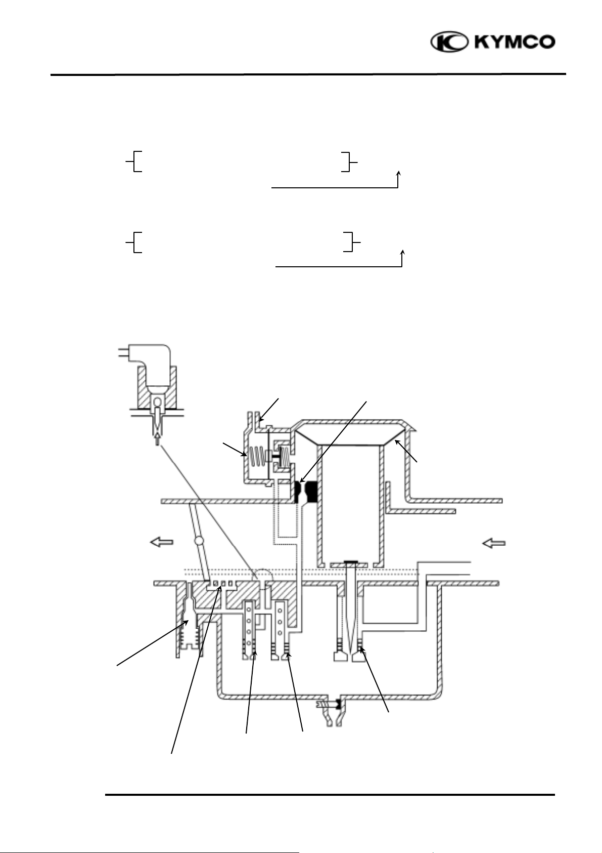
OPERATION OF CARBURETOR JETS
1. LOW SPEED
Venturi (slightly opened throttle valve)
Low Speed Air Inlet
※ Fuel in Float Chamber‡ Slow Jet
-------------------- Low Speed Small Jet Holes
2.MIDDLE SPEED
Venturi (halfway opened throttle valve)
High Speed Air Jet
※ Fuel in Float Chamber‡ Main Jet
Main Jet (The slow jet also works.)
Low & Middle Speed Supplementary Device:
Vacuum Tube
Low Speed Air Jet
Main Jet
Vacuum Diaphragm
Throttle
Valve
Low & Middle Speed Supplementary Fuel Inlets
Slow Jet
Bypass Jet
Pilot Screw
ACV
Air
※ Air
※ Air
Air Bleed Holes‡ Mixture…….
Air Bleed Holes‡ Mixture…….
Page 5
13. FUEL SYSTEM/CARBURETOR/
FUEL PUMP/ FUEL TANK
13-4
GRAND D INK 25 0
FUEL PUMP
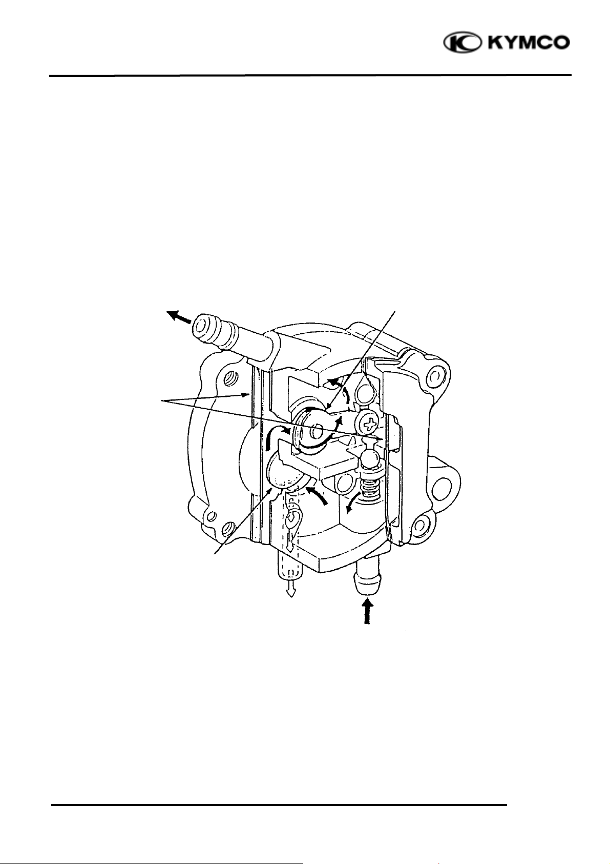
CONSTRUCTION:
The fuel pump adopted for this model is a vacuum-type fuel pump which utilizes the positive and
negative pulsating pressures produced by the engine crankcase to control the oil pump diaphragms
and deliver fuel from the fuel tank to the carburetor through the suction valve and outlet valve.
FUEL PUMP CONSTRUCTION
Diaphragms
Inlet
Outlet
Suction Valve
Outlet Valve
Pulsating Pressure
from Crankcase
Page 6
13. FUEL SYSTEM/CARBURETOR/
FUEL PUMP/ FUEL TANK
13-5
GRAND D INK 25 0
SERVICE INFORMATION
GENERAL INSTRUCTIONS
• When working with gasoline, keep away from sparks and flames.
• Note the locations of O-rings when disassembling and replace them with new ones during
assembly.
• Before float chamber disassembly, drain the residual gasoline from the float chamber.
• Do not try to disassemble the auto bystarter.
• When assembling the vacuum chamber and air cut-off valve, be careful not to damage the
diaphragms.
• All cables, fuel lines and wires must be routed and secured at correct locations.
• When removing the fuel tank, keep sparks and flames away from the working area.
• When removing the fuel tank, the remaining fuel in the tank must be lower than _ of the fuel tank
capacity to avoid gasoline overflowing.
• Fuel tank capacity: 10.5 liters
SPECIFICATIONS
SH50DA
Venturi dia. (mm)
CVK30
Identification number
CVK056A
Float level (mm)
18.5
Pilot screw opening
2_ ± _
Main jet
102#
Slow jet
38#
Idle speed
1700
Fuel pump output
40cc/1700rpm/10 Seconds
SPECIAL TOOLS
Float level gauge
Fuel unit remover
Page 7

13. FUEL SYSTEM/CARBURETOR/
FUEL PUMP/ FUEL TANK
13-6
GRAND D INK 25 0
TROUBLESHOOTING
Engine does not start Engine idles roughly, stalls or runs poorly
• No fuel in tank • Incorrect idle speed
• Restricted fuel line • Rich mixture
• Too much fuel getting to cylinder • Lean mixture
• Clogged air cleaner • Clogged air cleaner
• Contaminated fuel • Intake air leak
• Faulty fuel pump • Contaminated fuel
• Faulty air-cut off valve
• Damaged vacuum tube and connectors
• Damaged carburetor insulator
Throttle does not open fully, so engine stalls Rich mixture
• Damaged vacuum piston diaphragm • Auto bystarter valve opens excessively
• Clogged diaphragm hole • Faulty float valve
• Float level too high
Lean mixture • Clogged air jets
• Clogged fuel jets • Auto bystarter valve set plate installed in
• Clogged fuel tank cap breather hole
the wrong groove
• Clogged fuel filter •Clogged air cleaner
• Bent, kinked or restricted fuel line
• Faulty float valve
• Float level too low
• Faulty fuel pump or insufficient output
Engine is hard to start
• No fuel in tank
• Restricted fuel line
• Clogged fuel strainer
• Faulty fuel pump
• Broken or clogged vacuum tube
• Faulty or clogged charcoal canister
Lean mixture
• Clogged charcoal canister
• Bent, kinked or restricted fuel line
• Clogged fuel strainer
• Float level too low
Page 8

13. FUEL SYSTEM/CARBURETOR/
FUEL PUMP/ FUEL TANK
13-7
GRAND D INK 25 0
CARBURETOR REMOVAL
Remove the seat, met-in box and center
cover.
Disconnect the fuel tube and vacuum tube at
the carburetor.
Disconnect the auto bystarter wire.
Loosen the throttle cable adjusting nut and
lock nut, and disconnect the throttle cable
from the carburetor.
Loosen the air cleaner connecting tube band
and carburetor intake manifold band and then
remove the carburetor.
VACUUM CHAMBER
DISASSEMBLY
Loosen the drain screw and drain the fuel
from the float chamber.
Auto Bystarter Wire
Auto Bystarter
Fuel Tube
Intake Manifold Band
Air Cleaner Connecting Tube
Drain Screw
Throttle Cable
Page 9

13. FUEL SYSTEM/CARBURETOR/
FUEL PUMP/ FUEL TANK
13-8
GRAND D INK 25 0
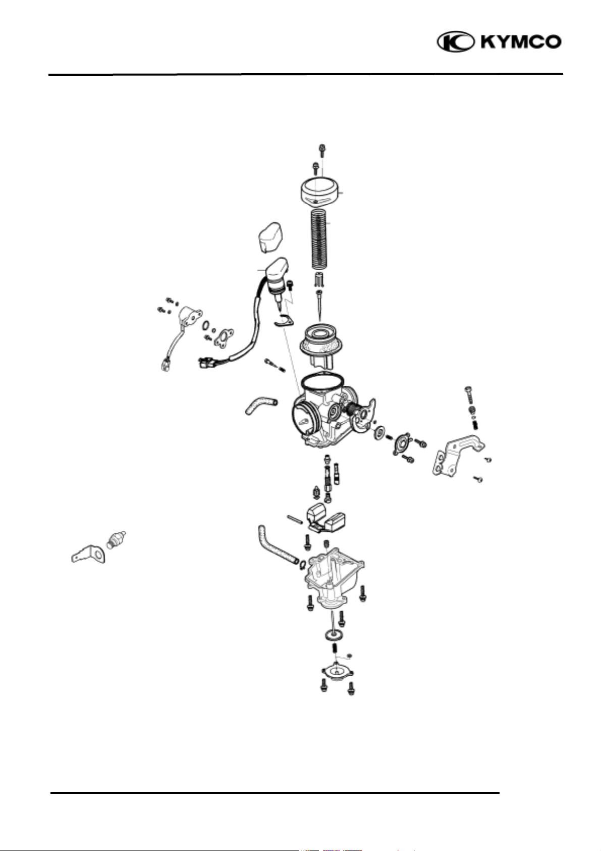
Remove the two vacuum chamber cover
screws and the cover.
Remove the compression spring and vacuum
piston.
Remove the needle holder, spring and jet
needle from the piston.
VACUUM PISTON INSPECTION
Inspect the vacuum piston and jet needle for
wear or damage.
Inspect the diaphragm for deterioration and
tears.
Vacuum Chamber Cover
Diaphragm
Screws
Spring
• Be careful not to damage the vacuum
piston diaphragm.
*
Vacuum Piston
Vacuum Piston
Needle Holder
Jet Needle
Page 10

13. FUEL SYSTEM/CARBURETOR/
FUEL PUMP/ FUEL TANK
13-9
GRAND D INK 25 0
FLOAT CHAMBER DISASSEMBLY
Remove the three float chamber screws and
the float chamber.
Remove the float pin, float and float valve.
FLOAT VALVE INSPECTION
Inspect the float valve seat contact area for
wear.
Float Chamber
Float Valve
Float
Float Pin
Float Valve Seat
Screws
Float Valve
Page 11

13. FUEL SYSTEM/CARBURETOR/
FUEL PUMP/ FUEL TANK
13-10
GRAND D INK 25 0
JETS/SCREWS REMOVAL
Remove the main jet, needle jet holder and
needle jet.
Remove the slow jet.
Clean the removed the main jet, needle jet
holder, needle jet and slow jet with detergent
oil.
Pilot Screw (P.S.)
Pilot Screw
Slow Jet
• Be sure to use clean detergent oil.
*
Main Jet
Needle Jet Holder
Needle Jet
• Before removing the pilot screw, turn
the pilot screw clockwise until it seats
lightly and record the rotating turns.
Do not force the pilot screw against its
seat to avoid seat damage.
*
Slow Jet
Main Jet
Page 12

13. FUEL SYSTEM/CARBURETOR/
FUEL PUMP/ FUEL TANK
13-11
GRAND D INK 25 0
AUTO BYSTARTER INSPECTION
/REMOVAL
AUTO BYSTARTER INSPECTION
Measure the resistance between the auto
bystarter wire terminals.
Resistance: 10W (10 minutes minimum
after stopping the engine)
If the reading is not within the limit, replace
the auto bystarter with a new one.
Connect a hose to the fuel enriching circuit
of the carburetor. Connect the auto
bystarter green/black wire to the positive (+)
terminal of a battery and black/white wire to
the negative (-) terminal. Wait 5 minutes and
blow the hose with mouth. If the passage is
blocked, the auto bystarter is normal.
Disconnect the auto bystarter from the
battery. Wait 30 minutes and blow the hose
with mouth.. If air can be blown into the
hose, the auto bystarter is normal.
AUTO BYSTARTER REMOVAL
Remove the one set plate screw and set plate
and then remove the auto bystarter from the
carburetor body.
Auto Bystarter
Hose
B/W
Screws
Set Plate
G/B
Page 13

13. FUEL SYSTEM/CARBURETOR/
FUEL PUMP/ FUEL TANK
13-12
GRAND D INK 25 0
AUTO BYSTARTER INSPECTION
Check the auto bystarter valve and needle
for nicks, wear or damage.
If any faulty part is found, replace the auto
bystarter with a new one.
AIR CUT-OFF VALVE (A.C.V.)
A.C.V. REMOVAL
Remove the two screws and the air cut-off
valve cover.
Remove the spring, diaphragm and O-rings.
Inspect the diaphragm and spring for wear or
damage.
Bystarter Needle
Air Cut-off Valve Cover
Bystarter Valve
Spring
Screws
Cover
Diaphragm
Page 14

13. FUEL SYSTEM/CARBURETOR/
FUEL PUMP/ FUEL TANK
13-13
GRAND D INK 25 0
CARBURETOR BODY CLEANING
Blow compressed air through all passages of
the carburetor body.
Install the O-ring onto the air-cut-off valve
body securely.
Install the diaphragm, spring, and cover.
Install and tighten the two screws attaching
the air cut-off valve cover.
Connect the hose.
Screws
Spring
Cover
Diaphragm
O-ring
• Make sure that no fuel jet is clogged.
*
• Install the O-ring with the flat face
toward the valve body side.
*
Page 15

13. FUEL SYSTEM/CARBURETOR/
FUEL PUMP/ FUEL TANK
13-14
GRAND D INK 25 0
ACCELERATING PUMP
DISASSEMBLY
Remove the two accelerating pump cover
screws and accelerating pump cover.
Remove the spring and accelerating pump
diaphragm.
INSPECTION
Inspect the accelerating pump diaphragm for
cracks, damage or deterioration. Replace if
necessary.
Assemble the accelerating pump in the
reverse order of disassembly.
AUTO BYSTARTER INSTALLATION
Install the auto bystarter and set plate.
Install and tighten the two screws.
Auto Bystarter
Screws
• Insert the auto bystarter into the
carburetor body until it bottoms and
position the set plate into the upper
groove in the bystarter.
• Install the set plate with its round face
facing down.
*
Screws
Spring
Cover
Diaphragm
O-ring
Page 16

13. FUEL SYSTEM/CARBURETOR/
FUEL PUMP/ FUEL TANK
13-15
GRAND D INK 25 0
FLOAT CHAMBER ASSEMBLY
Install the main jet.
Install the slow jet.
Install the pilot screw.
Install the float valve, float and float pin.
Float Valve
Float
Float Pin
Pilot Screw
Slow Jet
Main Jet
• Be sure to record the rotating turns
when it is removed.
*
Page 17

13. FUEL SYSTEM/CARBURETOR/
FUEL PUMP/ FUEL TANK
13-16
GRAND D INK 25 0
FLOAT LEVEL INSPECTION
Measure the float level at the location of the
main jet (just contacting the float valve).
Float Level: 18.5±1.0mm
Replace the float if the level is incorrect.
Check the operation of the float and then
reinstall the float chamber.
VACUUM CHAMBER ASSEMBLY
First install the jet needle and spring into the
vacuum chamber and then install the needle
holder.
Install the vacuum piston into the carburetor
body.
Install the spring.
Install the vacuum chamber cover and tighten
it with the two screws.
Diaphragm
Float
• Be careful not to let the diaphragm slip.
• If the diaphragm cannot be positioned
correctly because of expansion, dry the
diaphragm before installation.
*
Spring
Vacuum Piston
Vacuum Piston
Needle Holder
Jet Needle
Page 18

13. FUEL SYSTEM/CARBURETOR/
FUEL PUMP/ FUEL TANK
13-17
GRAND D INK 25 0
Check the heater with battery.
If the heater is getting hot, means the heater
without problem, otherwise the heater has to
be changed.
CARBURETOR INSTALLATION
Tighten the drain screw.
Install the carburetor onto the intake
manifold and tighten the band.
Install the air cleaner connecting tube and
tighten the band.
Connect the throttle cable to the carburetor.
Connect the auto bystarter wire.
Connect the fuel tube and vacuum tube to
the carburetor.
Perform the following inspections and
adjustments:
•Throttle grip free play (!3-3)
•Idle speed (!3-6)
Install the seat, met-in box and frame center
cover.
Auto Bystarter Wire
Fuel Tube
Intake Manifold Band
Air Cleaner Connecting
Tube Band
Heater
• After connecting the throttle cable,
adjust the throttle grip free play to
2_ 6mm.
*
Throttle Cable
Page 19

13. FUEL SYSTEM/CARBURETOR/
FUEL PUMP/ FUEL TANK
13-18
GRAND D INK 25 0
FUEL PUMP REMOVAL
Remove the frame center cover.
Disconnect the fuel pump inlet, outlet and
vacuum tubes.
Remove the two fuel pump attaching bolts
and the fuel pump.
FUEL PUMP DISASSEMBLY
Remove the four fuel pump body screws.
Disassemble the fuel pump.
Inlet
Screws
Fuel Strainer
Outlet Tube
Vacuum Tube
Inlet Tube
Vacuum Tube
Outlet
Page 20

13. FUEL SYSTEM/CARBURETOR/
FUEL PUMP/ FUEL TANK
13-19
GRAND D INK 25 0
FUEL PUMP INSPECTION
Inspect the fuel pump diaphragms A and B
for damage.
Inspect each gasket for damage.
Inspect the suction valve, outlet valve and
relief valve in the fuel pump body for
damage, cracks or foreign matters.
FUEL PUMP ASSEMBLY
Assemble the fuel pump in the reverse order
of disassembly.
Inlet
Spring
Suction Valve
Diaphragm
Outlet Valve
Gaskets
Relief Valve
Outlet
Dowel Pins
Dowel Pin Holes
Fuel Pump Body
• During assembly, be sure to install the
gaskets and diaphragms properly to
avoid damage.
• Do not allow any foreign matter to
enter the fuel pump during assembly.
*
Spring
Page 21

13. FUEL SYSTEM/CARBURETOR/
FUEL PUMP/ FUEL TANK
13-20
GRAND D INK 25 0
FUEL PUMP INSTALLATION
Install the fuel pump and secure it with the
two bolts.
Connect the fuel pump inlet, outlet and
vacuum tubes.
Install the seat, met-in box and frame center
cover.
Measure the fuel pump output.
Start the engine and disconnect the fuel
outlet tube and place a clean container under
the tube to check the fuel output.
Output: 40cc/1700rpm/10 seconds .
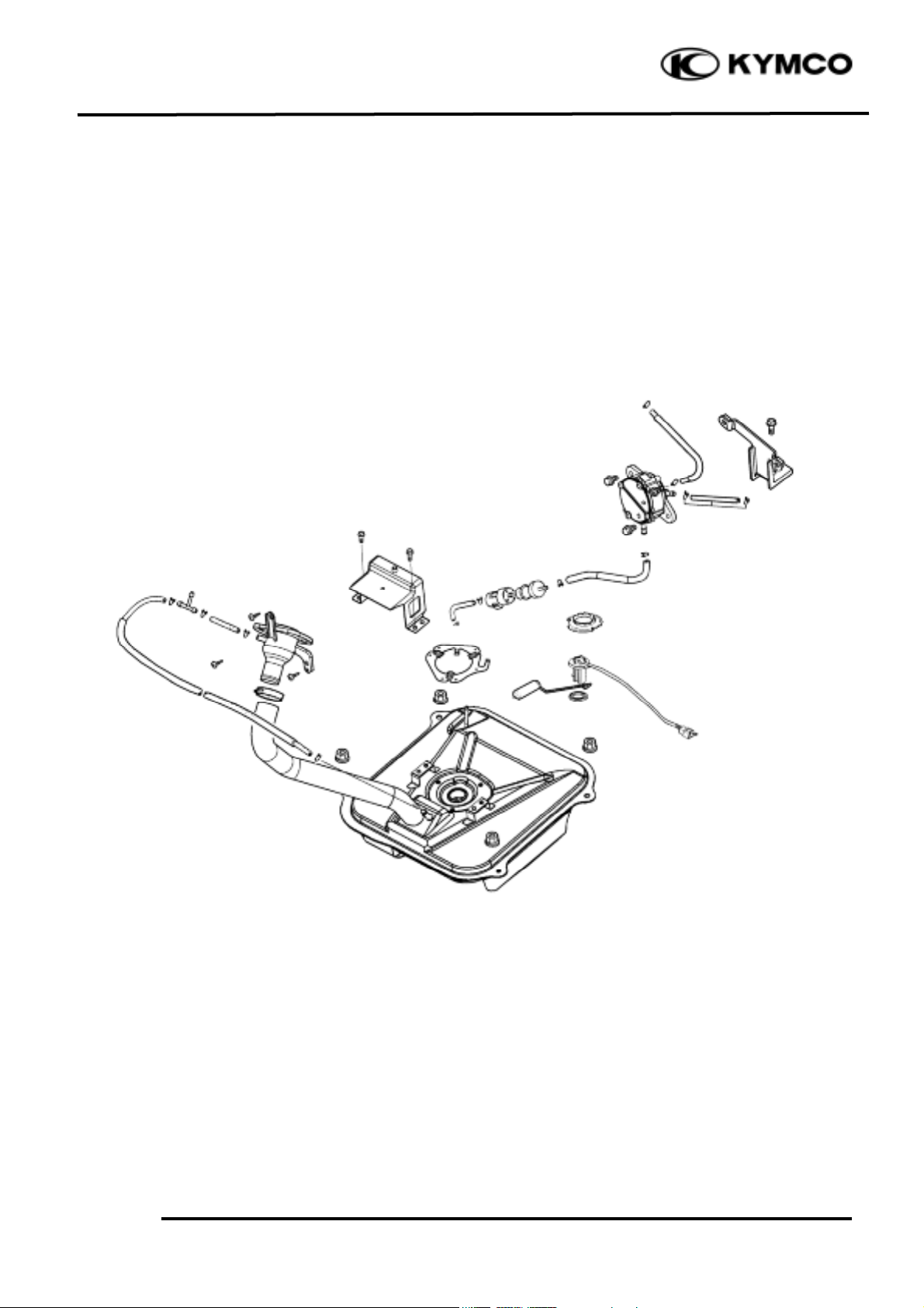
FUEL TANK REMOVAL
Remove the floor board. (!2-4)
Remove the leg shield . (!2-5)
Disconnect the fuel unit wire connector.
Remove the fuel tube between the fuel tank
and the fuel filler.
Disconnect the fuel vapor tube.
Remove the fuel tank.
The installation sequence is the reverse of
removal.
Container
Fuel Pump
Fuel Pump
Outlet Tube
Fuel Strainer
Outlet Tube
Vacuum Tube
Inlet Tube
Fuel Unit
Fuel Vapor Tube
Fuel Strainer
Tube to Fuel Filler
Page 22

13. FUEL SYSTEM/CARBURETOR/
FUEL PUMP/ FUEL TANK
13-21
GRAND D INK 25 0
FUEL STRAINER REMOVAL
Remove the fuel strainer from the fuel tank.
INSPECTION
Inspect if the fuel strainer is clogged and
clean it with compressed air.
INSTALLATION
Install the fuel strainer with its arrow mark
toward the fuel pump.
• When removing the fuel strainer, do not
allow flames or sparks near the
working area and drain the residual
gasoline into a container.
*
Fuel Strainer
 Loading...