

Page 1

17. IGNITION SYSTEM
17-0
GRAND DINK 125/15 0
17
__________________________________________________________________________________
__________________________________________________________________________________
__________________________________________________________________________________
__________________________________________________________________________________
__________________________________________________________________________________
IGNITION SYSTEM
__________________________________________________________________________________
IGNITION SYSTEM LAYOUT --------------------------------------- 17-1
SERVICE INFORMATION -------------------------------------------- 17-2
TROUBLESHOOTING ------------------------------------------------- 17-2
SPARK PLUG ----------------------------------------------------------- 17-3
IGNITION COIL INSPECTION --------------------------------------- 17-3
A.C. GENERATOR INSPECTION ------------------------------------ 17-4
CDI UNIT RESISTANCE INSPECTION----------------------------- 17-5
17
Page 2
17. IGNITION SYSTEM
17-1
GRAND DINK 125/15 0
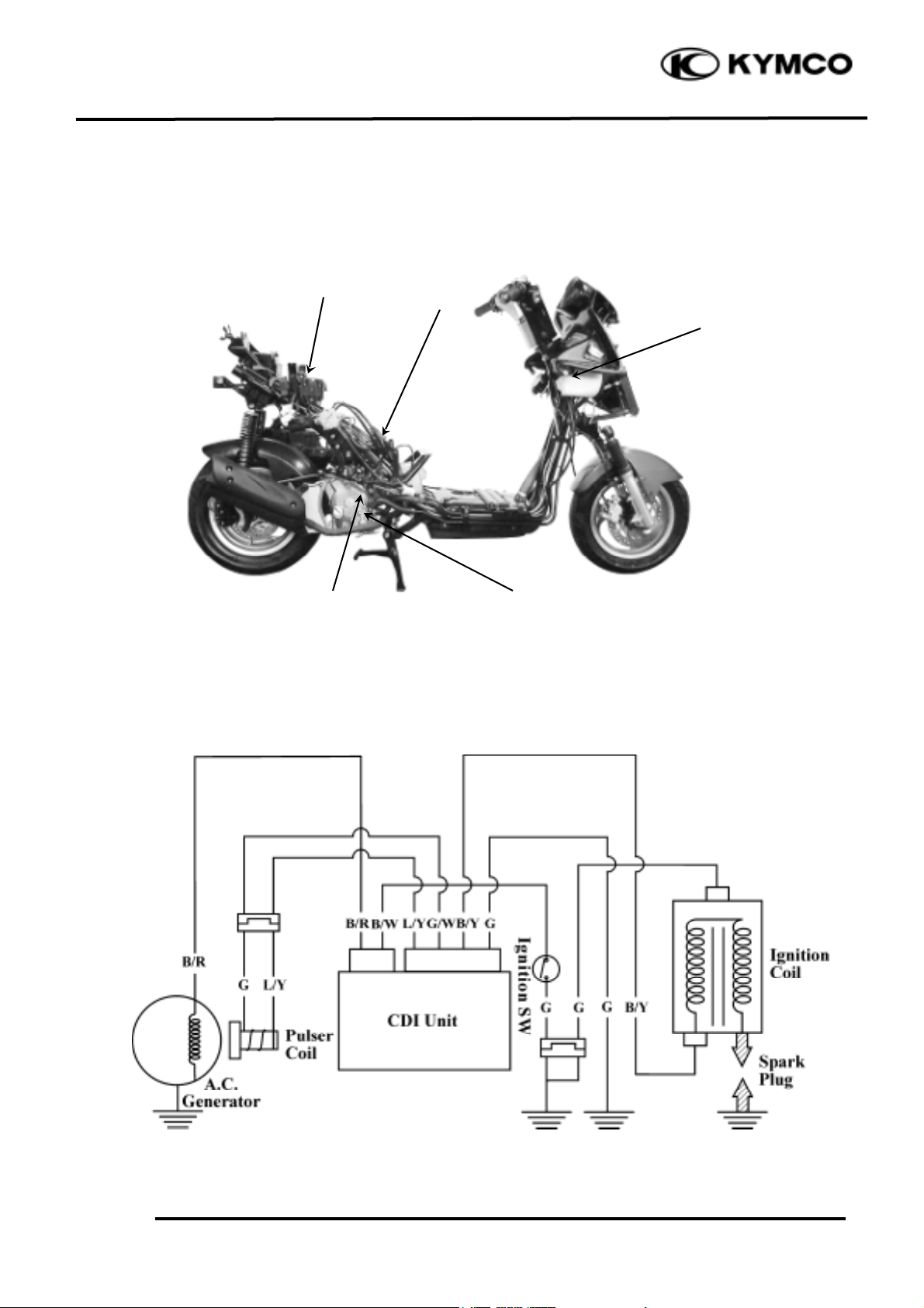
IGNITION SYSTEM LAYOUT
IGNITION CIRCUIT
Pulser Coil
Ignition Switch
Ignition Coil
CDI Unit
A.C. Generator
Page 3

17. IGNITION SYSTEM
17-2
GRAND DINK 125/15 0
SERVICE INFORMATION
GENERAL INSTRUCTIONS
• Check the ignition system according to the sequence specified in the Troubleshooting. (!1-28)
• The ignition system adopts CDI unit and the ignition timing cannot be adjusted.
• If the timing is incorrect, inspect the CDI unit and A.C. generator and replace any faulty parts.
Inspect the CDI unit with a CDI tester
• Loose connector and poor wire connection are the main causes of faulty ignition system. Check
each connector before operation.
• Use of spark plug with improper heat range is the main cause of poor engine performance.
• The inspections in this section are focused on maximum voltage. The inspection of ignition coil
resistance is also described in this section.
• Inspect the ignition switch according to the continuity table specified in page 20-3.
• Inspect the spark plug referring to Section 3.
• Remove the A.C. generator and pulser coil referring to Section 10.
SPECIFICATIONS
Item
Standard
Standard type
NGK DP7EA9
Spark plug
Hot type
NGK DP6EA9
Cold type
NGK DP8EA9
Spark plug gap
0.8_ 0.9mm
Ignition timing
“F” mark
Full advance
BTDC 10°±1.5°
BTDC 27°±2°
Primary coil
0.16_ 1W
Ignition coil resistance
(20℃ )
Secondary
without plug cap
3.6_ 4.6KW
coil
with plug cap
7.6_ 9.6KW
Pulser coil resistance (20℃ )
50_ 170W
Exciter coil resistance (20℃ )
50_ 350W
Ignition coil primary side max. voltage
244V
Pulser coil max. voltage
10.5V
Exciter coil max. voltage
244V
TESTING INSTRUMENT
Electric tester
TROUBLESHOOTING
No spark at plug Engine starts but turns poorly
• Faulty spark plug • Ignition primary circuit
• Poorly connected, broken or shorted wire —Faulty ignition coil
• Faulty ignition switch —Poorly connected wire or connector
• Faulty ignition coil —Poorly contacted ignition switch
• Faulty CDI unit • Ignition secondary circuit
• Faulty A.C. generator —Faulty ignition coil
—Faulty spark plug
—Faulty high-tension wire
—Poorly insulated plug cap
• Improper ignition timing
—Faulty A.C. generator
—Stator not installed properly
—Faulty CDI unit
Page 4

17. IGNITION SYSTEM
17-3
GRAND DINK 125/15 0
SPARK PLUG
For spark plug inspection and adjustment,
refer to page 3-5.
IGNITION COIL INSPECTION
Remove the seat and met-in box. (!2-3)
Remove the ignition coil
IGNITION COIL CONTINUITY TEST
Inspect the continuity of the ignition coil,
primary coil and secondary coil.
Measure the ignition coil resistances at
20℃ .
SECONDARY COIL WITH PLUG CAP
Primary coil
0.16_ 1W
Secondary coil
without plug cap
3.4_ 4.6KW
Secondary coil with
plug cap
7.6_ 9.6KW
SECONDARY COIL WITHOUT PLUG
CAP
Ignition Coil
This is a general test. Accurate ignition
coil test must be performed with a CDI
tester.
*
Ignition Coil
Secondary Coil
Primary Coil
Ignition Coil
Page 5

17. IGNITION SYSTEM
17-4
GRAND DINK 125/15 0
A .C. GENERATOR INSPECTION
EXCITER COIL/PULSER COIL
INSPECTION
Remove the frame right cover. (!2-4)
Disconnect the A.C. generator connector.
Measure the exciter coil resistance between
the black/red wire terminal and ground.
Black/red_ Ground
50_ 250W
For A.C. generator removal/installation, refer
to pages 10-3 and 10-6.
Disconnect the pulser coil wire coupler.
Measure the pulser coil resistance between
the blue/white and green/white wire terminals.
Blue/white_ Green/white
50_ 170W
A.C. Generator Connector
This test is performed with the stator
installed in the engine.
*
Measure the resistance in the XW range.
*
Pulser Coil Wire Coupler
Page 6

17. IGNITION SYSTEM
17-5
GRAND DINK 125/15 0
CDI UNIT
RESISTANCE INSPECTION
Measure the resistance between the terminals.
Replace the CDI unit if the readings are not
within the specifications in the table below.
Use the x KW range for the Sanwa Tester.
Use the x 100W range for the Kowa Tester.
Unit: KW
(+)Probe
(-)Probe
SW
(Black/White)
EXT
(Black/Red)
PC
(Blue/Yellow)
E Å Ç
(Green •
Green/White)
IGN
(Black/Yellow)
SW
(Black/White)
∞∞∞
∞
EXT
(Black/Red)
1-10
100-200
250-450
∞
PC
(Blue/Yellow)
50-90
30-100
20-80
∞
E Å Ç
(Green •
Green/White)
5-20
1-10
5-40
∞
IGN
(Black/Yellow)
∞∞∞
∞
IGN
(Black/Yellow)
PC
(Blue/Yellow)
EXT
(Black/Red)
SW
(Black/White)
E Ç
(Green/White)
E Å
(Green)
• Due to the semiconductor in circuit, it
is necessary to use a specified tester
for accurate testing. Use of an
improper tester in an improper range
may give false readings.
• Use a Sanwa Electric Tester (07308-
0020000) or Kowa Electric Tester
(TH-5H).
• In this table, “Needle swings then
returns” indicates that there is a
charging current applied to a condenser.
The needle will then remain at “∞ ”
unless the condenser is discharged.
*
 Loading...