

Page 1

8. DRIVE AND DRIVEN PULLEYS/
KICK STARTER
8-0
GRAND DINK 125/15 0
8
__________________________________________________________________________________
__________________________________________________________________________________
__________________________________________________________________________________
__________________________________________________________________________________
__________________________________________________________________________________
DRIVE AND DRIVEN PULLEYS/
KICK STARTER
__________________________________________________________________________________
SCHEMATIC DRAWING ---------------------------------------------- 8- 1
SERVICE INFORMATION -------------------------------------------- 8- 2
TROUBLESHOOTING ------------------------------------------------- 8- 2
LEFT CRANKCASE COVER------------------------------------------ 8- 3
DRIVE PULLEY -------------------------------------------------------- 8- 4
CLUTCH/DRIVEN PULLEY ------------------------------------------ 8- 8
KICK STARTER -------------------------------------------------------- 8-15
8
Page 2
8. DRIVE AND DRIVEN PULLEYS/
KICK STARTER
8-1
GRAND DINK 125/15 0
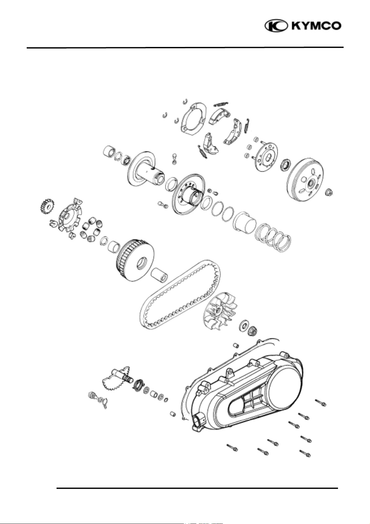
SCHEMATIC DRAWING
Page 3
8. DRIVE AND DRIVEN PULLEYS/
KICK STARTER
8-2
GRAND DINK 125/15 0
SERVICE INFORMATION
GENERAL INSTRUCTIONS
• The drive pulley, clutch and driven pulley can be serviced with the engine installed.
• Avoid getting grease and oil on the drive belt and pulley faces. Remove any oil or grease from
them to minimize the slipping of drive belt and drive pulley.
SPECIFICATIONS
Item
Standard (mm)
Service Limit (mm)
Movable drive face bushing I.D.
33.000_ 33.025
33.06
Drive face collar O.D.
32.006_ 32.009
31.90
Drive belt width
19.0
17.5
Clutch lining thickness
3.963_ 4.037
2.0
Clutch outer I.D.
130.0_ 130.2
130.5
Driven face spring free length
88.3
83.2
Driven face O.D.
33.965_ 33.985
33.94
Movable driven face I.D.
34.00_ 34.025
34.06
Weight roller O.D.
16.99_ 17.00
16.00
TORQUE VALUES
Drive face nut 49.0_ 58.8N-m
Clutch outer nut 49.0_ 58.8N-m
Clutch drive plate nut 49.0_ 58.8N-m
SPECIAL TOOLS
Universal holder Clutch spring compressor
Bearing driver Lock nut wrench, 39mm
Kick starter spring remover
TROUBLESHOOTING
Engine starts but motorcycle won‘t move Lack of power
• Worn drive belt • Worn drive belt
• Broken ramp plate • Weak driven face spring
• Worn or damaged clutch lining • Worn weight roller
• Broken driven face spring • Faulty driven face
Engine stalls or motorcycle creeps
• Broken clutch weight spring
Page 4
8. DRIVE AND DRIVEN PULLEYS/
KICK STARTER
8-3
GRAND DINK 125/15 0
LEFT CRANKCASE COVER
REMOVAL
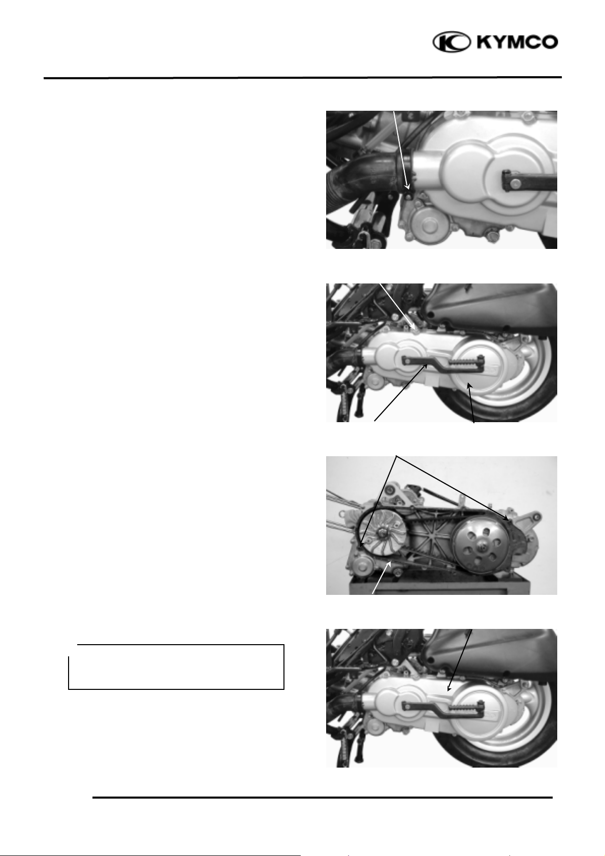
Loosen the drive belt air tube band screw.
Remove the left crankcase cover bolts and left
crankcase cover.
Remove the seal rubber and dowel pins.
INSTALLATION
Install the dowel pins and the gasket.
Install the left crankcase cover.
Install the cable clamp to the specified
location. Install and tighten the left crankcase
cover bolts.
Kick Lever
Left Crankcase Cover
Air Tube Band
Bolts
• Do not pull out the kick starter spindle.
Press in the kick starter spindle when
installing the left crankcase cover.
*
Dowel Pins
Gasket
Left Crankcase Cover
Page 5
8. DRIVE AND DRIVEN PULLEYS/
KICK STARTER
8-4
GRAND DINK 125/15 0
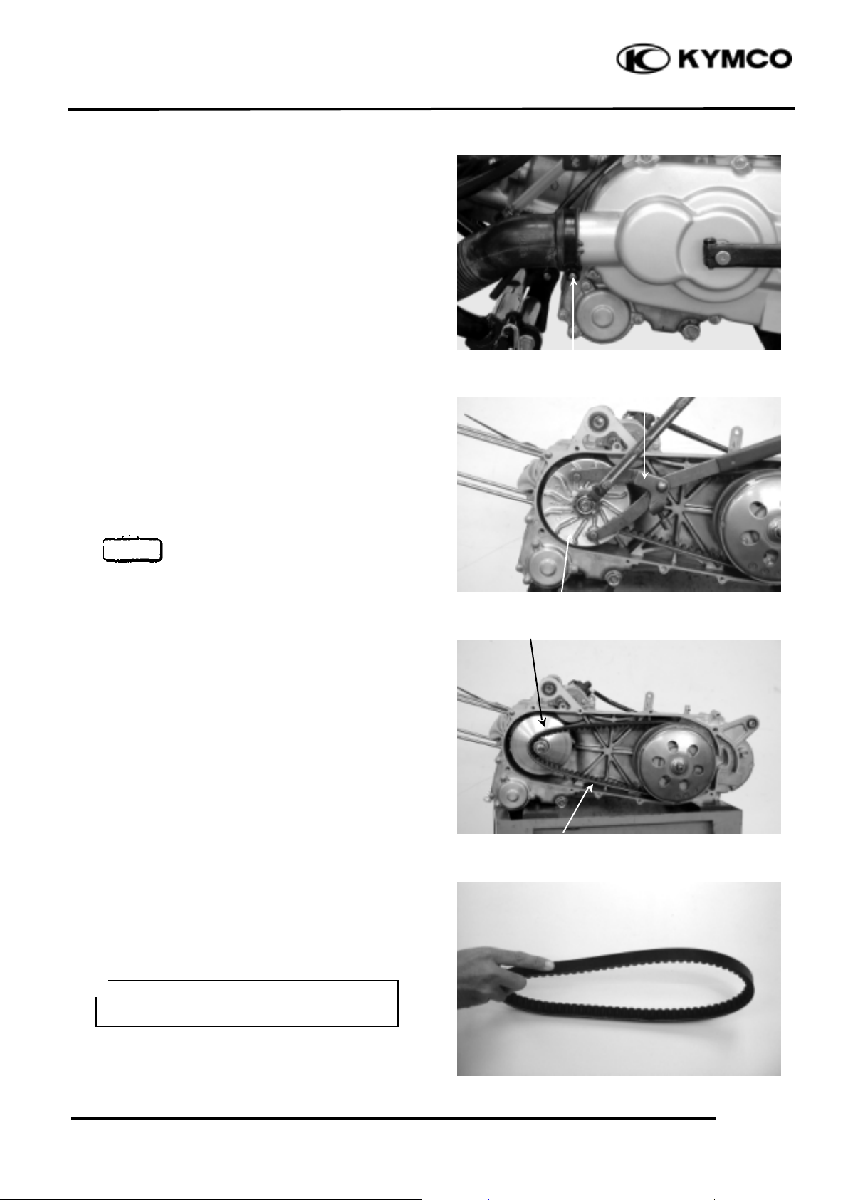
Install the drive belt air tube and tighten the
tube band screw.
DRIVE PULLEY
REMOVAL
Remove the left crankcase cover.
Hold the drive pulley using an universal
holder and remove the drive face nut and
washer.
Remove the drive pulley face.
Universal Holder
Remove the drive belt from the movable drive
face.
INSPECTION
Check the drive belt for cracks, separation or
abnormal or excessive wear.
Measure the drive belt width.
Service Limit: 17.5mm replace if below
Drive Pulley Face
Universal Holder
• Use specified genuine parts for
replace-ment.
*
Movable Drive Face
Drive Belt
Tube Band Screw
Special
Page 6
8. DRIVE AND DRIVEN PULLEYS/
KICK STARTER
8-5
GRAND DINK 125/15 0
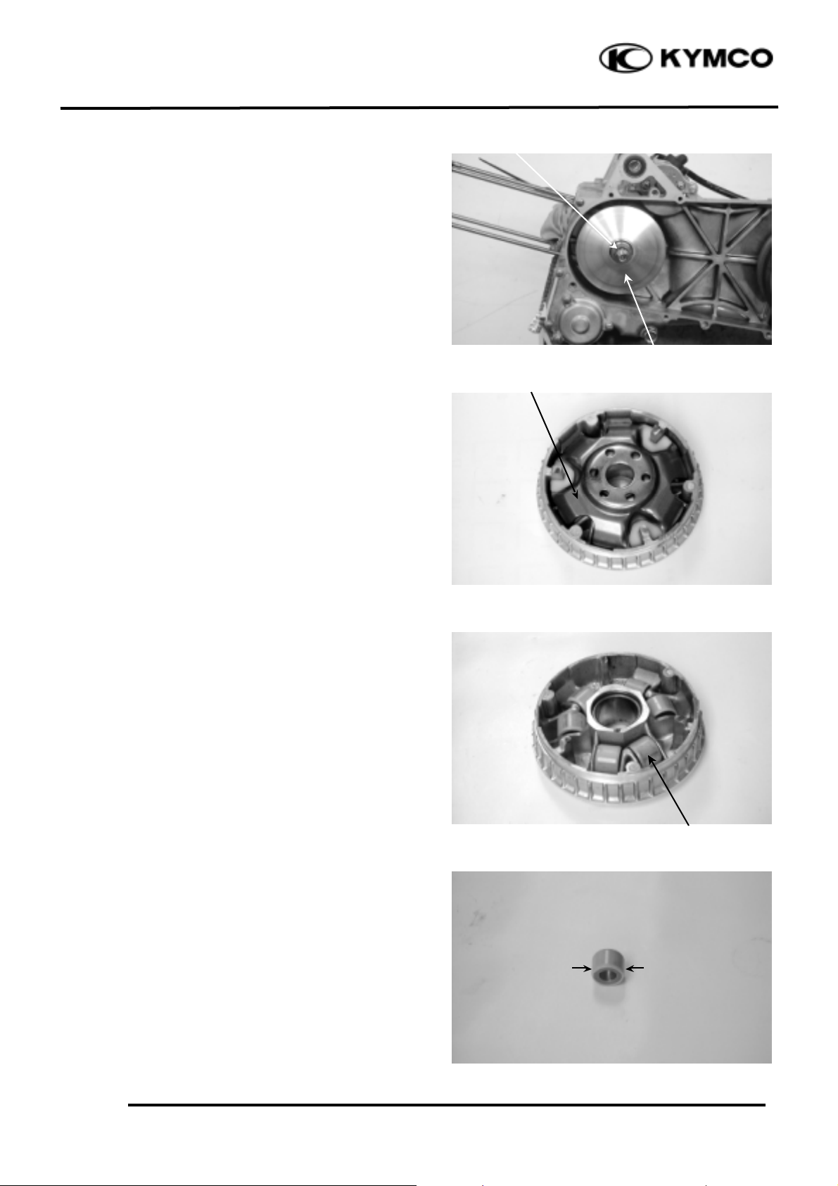
Remove the movable drive face assembly.
Remove the drive pulley collar.
DISASSEMBLY
Remove the ramp plate.
Remove the weight rollers.
INSPECTION
Check each weight roller for wear or damage.
Measure each weight roller O.D.
Service Limit: 16.00mm replace if below
Drive Pulley Collar
Ramp Plate
Weight Roller
Movable Drive Face Assembly
Page 7

8. DRIVE AND DRIVEN PULLEYS/
KICK STARTER
8-6
GRAND DINK 125/15 0
Measure the movable drive face bushing
assemblyy I.D.
Service Limit: 27.20mm replace if over
Check the drive pulley collar for wear or
damage.
Measure the O.D. of the drive pulley collar
sliding surface.
Service Limit: 26.90mm replace if below
ASSEMBLY
Install the weight rollers into the movable
drive face.
Weight Roller
Page 8

8. DRIVE AND DRIVEN PULLEYS/
KICK STARTER
8-7
GRAND DINK 125/15 0
Install the ramp plate.
Insert the drive pulley collar into the movable
drive face.
INSTALLATION
Install the movable drive face onto the
crankshaft.
Lay the drive belt on the driven pulley.
Set the drive belt on the drive pulley collar.
Drive Pulley Collar
Ramp Plate
Driven Pulley
Movable Drive Face Assembly
Drive Pulley Collar
Drive Belt
Page 9

8. DRIVE AND DRIVEN PULLEYS/
KICK STARTER
8-8
GRAND DINK 125/15 0
Install the drive pulley face, washer and drive
face nut.
Hold the drive pulley with the universal
holder and tighten the drive face nut.
Torque: 49.0_ 58.5N-m
Universal Holder
CLUTCH/DRIVEN PULLEY
Remove the left crankcase cover. (!8-3)
Remove the drive pulley and drive belt. (!8-
4)
Hold the clutch outer with the universal
holder and remove the clutch outer nut.
Universal Holder
Remove the clutch outer.
INSPECTION
Inspect the clutch outer for wear or damage.
Measure the clutch outer I.D.
Service Limit: 130.5mm replace if over
Drive Pulley Face
Washer
Special
Special
• Do not get oil or grease on the
drive belt or drive pulley faces.
*
Clutch Outer
Drive Face Nut
Drive Pulley
Universal Holder
Universal Holder
Page 10

8. DRIVE AND DRIVEN PULLEYS/
KICK STARTER
8-9
GRAND DINK 125/15 0
Check the clutch shoes for wear or damage.
Measure the clutch lining thickness.
Service Limit: 2.0mm replace if below
CLUTCH/DRIVEN PULLEY
DISASSEMBLY
Hold the clutch/driven pulley assembly with
the clutch spring compressor.
Clutch Spring Compressor
Set the tool in a vise and remove the clutch
drive plate nut.
Lock Nut Wrench, 39mm
Loosen the clutch spring compressor and
disassemble the clutch/driven pulley
assembly.
Remove the seal collar.
Clutch/Driven Pulley
Special
Special
Clutch Spring Compressor
• Be sure to use a clutch spring
compressor to avoid spring damage.
*
Lock Nut Wrench
Page 11

8. DRIVE AND DRIVEN PULLEYS/
KICK STARTER
8-10
GRAND DINK 125/15 0
Pull out the guide roller pins and guide rollers.
Remove the movable driven face from the
driven face.
Remove the oil seal from the movable driven
face.
INSPECTION
Measure the driven face spring free length.
Service Limit: 83.2mm replace if below
Check the driven face assembly for wear or
damage.
Measure the driven face O.D.
Service Limit: 33.94mm replace if below
Movable Driven Face
Guide Roller Pin
O-ring
Guide Roller
Oil Seal
Page 12

8. DRIVE AND DRIVEN PULLEYS/
KICK STARTER
8-11
GRAND DINK 125/15 0
Check the movable driven face for wear or
damage.
Measure the movable driven face I.D.
Service Limit: 34.06mm replace if over
DRIVEN PULLEY FACE BEARING
REPLACEMENT
Check the bearings for play and replace them
if they have excessive play.
Drive the inner needle bearing out of the
driven pulley face.
Remove the snap ring and drive the outer
bearing out of the driven face.
Apply grease to the outer bearing.
Drive a new outer bearing into the driven face
with the sealed end facing up.
Bearing Driver
Seat the snap ring in its groove.
Apply grease to the driven face bore areas.
Snap Ring
Inner Bearing
Outer Bearing
• Discard the removed bearing and
replace with a new one.
*
Pack all bearing cavities with 9_ 9.5g
grease.
*
• Discard the removed bearing and
replace with a new one.
*
Special
Page 13

8. DRIVE AND DRIVEN PULLEYS/
KICK STARTER
8-12
GRAND DINK 125/15 0
Press a new needle bearing into the driven
face.
Bearing Driver
CLUTCH DISASSEMBLY
Remove the circlips and retainer plate to
disassemble the clutch.
Circlips
Retainer Plate
Special
• Keep grease off the clutch
linings.
*
Clutch Lining
Page 14

8. DRIVE AND DRIVEN PULLEYS/
KICK STARTER
8-13
GRAND DINK 125/15 0
CLUTCH ASSEMBLY
Install the damper rubbers on the drive plate
pins.
Install the clutch weights/shoes and clutch
springs onto the drive plate.
Install the retainer plate and secure with the
circlips.
CLUTCH/DRIVEN PULLEY ASSEMBLY
Clean the pulley faces and remove any grease
from them.
Apply grease to the O-rings and install them
onto the moveable driven face.
Circlips
Drive Plate
Movable Driven Face
Page 15

8. DRIVE AND DRIVEN PULLEYS/
KICK STARTER
8-14
GRAND DINK 125/15 0
Install the movable driven face onto the
driven face.
Apply grease to the guide rollers and guide
roller pins and then install them into the holes
of the driven face.
Install the seal collar.
Remove any excessive grease.
Set the driven pulley assembly, driven face
spring and clutch assembly onto the clutch
spring compressor.
Compress the tool and install the drive plate
nut.
Set the tool in a vise and tighten the drive
plate nut to the specified torque.
Torque: 49.0_ 58.8N-m
Clutch Spring Compressor
Outer Driver, 32x35mm
INSTALLATION
Install the clutch/driven pulley onto the drive
shaft.
• Be sure to clean the driven face
off any grease.
*
• Align the flat surface of the driven
face with the flat on the clutch drive
plate.
*
• Keep grease off the drive shaft.
*
Movable Driven Face
Guide Roller Pin
Seal Collar
Guide Roller
Clutch/Driven Pulley
Driven Face
Clutch Spring Compressor
Lock Nut Wrench
• Be sure to use a clutch spring
compressor to avoid spring damage.
*
Special
Page 16

8. DRIVE AND DRIVEN PULLEYS/
KICK STARTER
8-15
GRAND DINK 125/15 0
Install the clutch outer.
Hold the clutch outer with the universal
holder.
Install and tighten the clutch outer nut.
Torque: 49.0_ 58.8kg-m
Universal Holder
Install the drive belt. (!8-7)
Install the left crankcase cover. (!8-3)
KICK STARTER
REMOVAL
Remove the left crankcase cover. (!8-3)
Remove the seal rubber and dowel pins.
Remove the kick lever.
Remove the circlip and washer from the kick
starter spindle.
Gently turn the kick starter spindle to remove
the starter driven gear together with the
friction spring.
Remove the kick starter spindle and return
spring from the left crankcase cover.
Remove the kick starter spindle bushing.
Special
Return Spring
Kick Starter Spindle
Friction Spring
Kick Starter Spindle
Starter Driven Gear
Kick Lever
Clutch Outer
Page 17

8. DRIVE AND DRIVEN PULLEYS/
KICK STARTER
8-16
GRAND DINK 125/15 0
INSPECTION
Inspect the kick starter spindle and gear for
wear or damage.
Inspect the return spring for weakness or
damage.
Inspect the kick starter spindle bushings for
wear or damage.
Inspect the starter driven gear for wear or
damage.
Inspect the friction spring for wear or
damage.
Inspect the kick starter spindle and starter
driven gear forcing parts for wear or damage.
INSTALLATION
Install the kick starter spindle bushings and
return spring onto the left crankcase cover.
Install the starter driven gear and friction
spring as the figure shown.
Starter Driven Gear Shaft Forcing Part
Friction Spring
Starter Driven Gear
Spindle
Return Spring
Plastic Bushing
Spindle Bushing
Starting Ratchet
Kick Starter Spindle Forcing
Friction Spring
Kick Starter Spindle
When installing the return spring, use a
screw driver to press the inward and
outward return spring hooks into their
original positions respectively.
*
Page 18

8. DRIVE AND DRIVEN PULLEYS/
KICK STARTER
8-17
GRAND DINK 125/15 0
Install the kick lever.
Install the left crankcase cover and tighten the
cover bolts diagonally.
Connect the drive belt air tube and tighten the
band screw.
LEFT CRANKCASE COVER BEARING
INSPECTION
Inspect the bearing into the left crankcase
cove for loose, wear or damage.
If any abnormal problem is found, replace the
bearing with a new one.
Left Crankcase Cover
 Loading...