

Page 1
5. FUEL SYSTEM
5-0
FILLY LX 50
5
5
Page 2
5. FUEL SYSTEM
5-1
FILLY LX 50
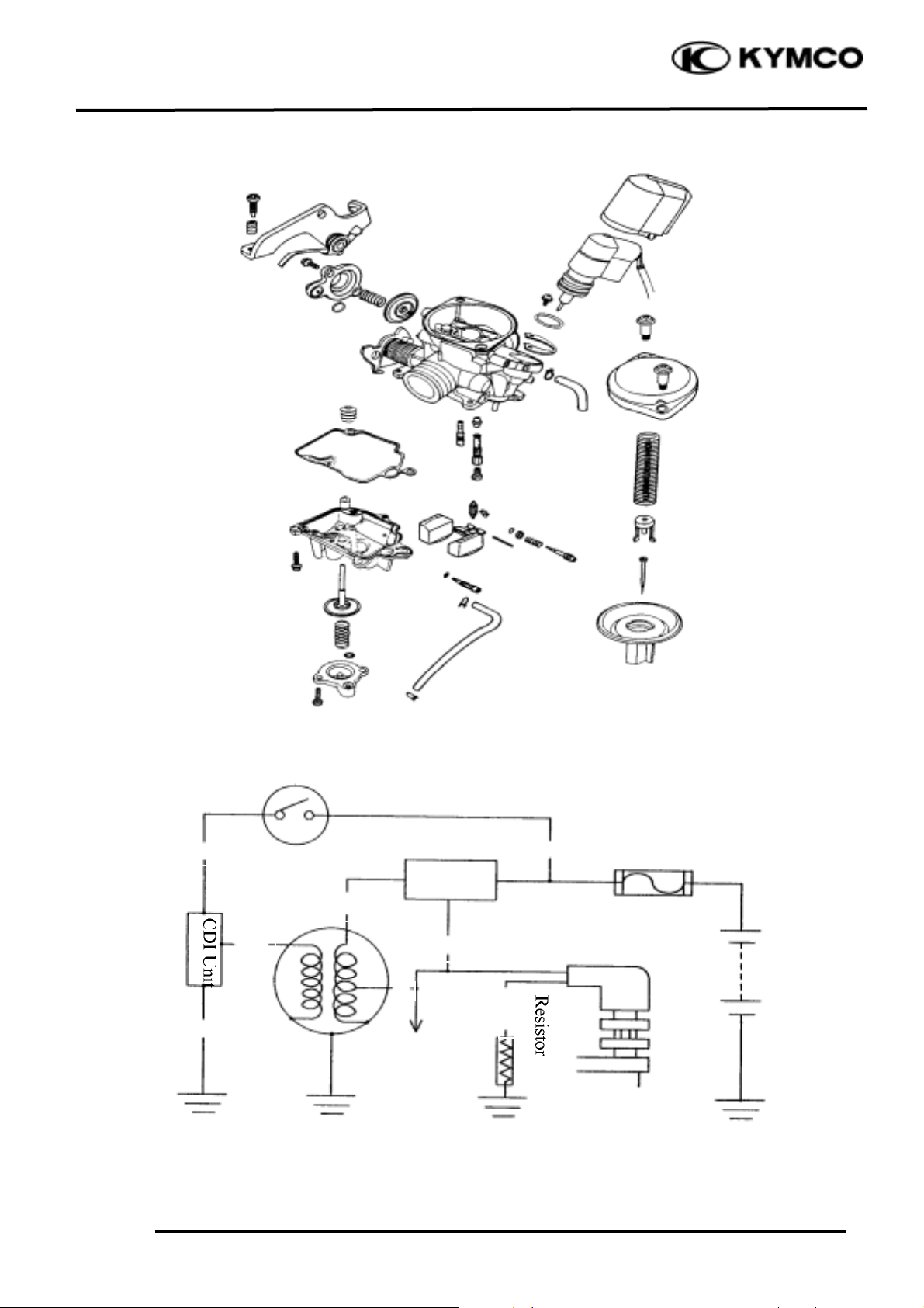
Fuse
12V Battery
Regulator
/Rectifier
L/Y
W
Auto Bystarter
Ignition Switch
BGY
Y
Lighting
System
5W
5W
G/B
M
Page 3
5. FUEL SYSTEM
5-2
FILLY LX 50
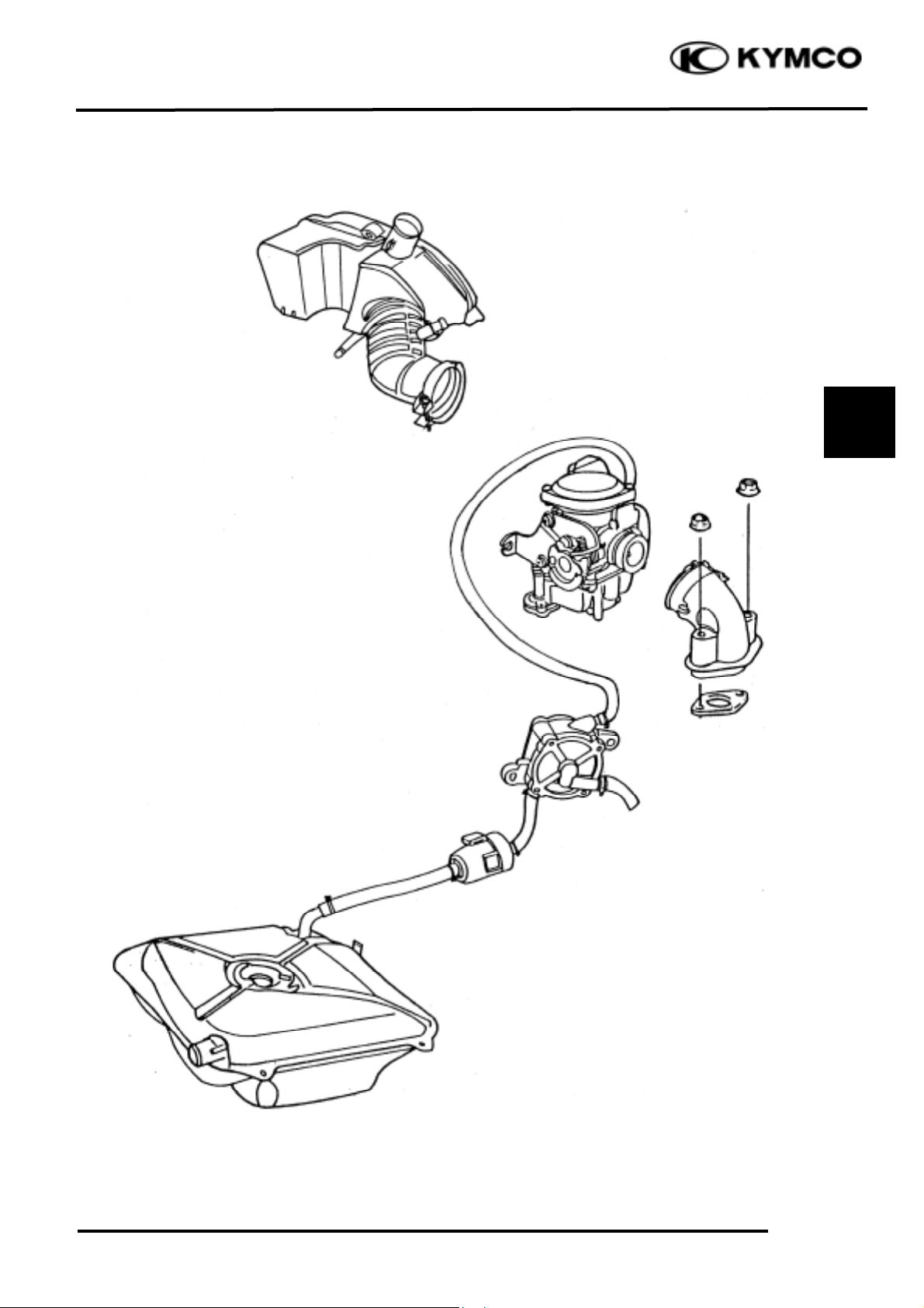
FUEL PUMP
CONSTRUCTION:
The fuel pump adopted for this model is a vacuum-type fuel pump which utilizes the positive and
negative pulsating pressures produced by the engine crankcase to control the oil pump diaphragms
and deliver fuel from the fuel tank to the carburetor through the suction valve and outlet valve.
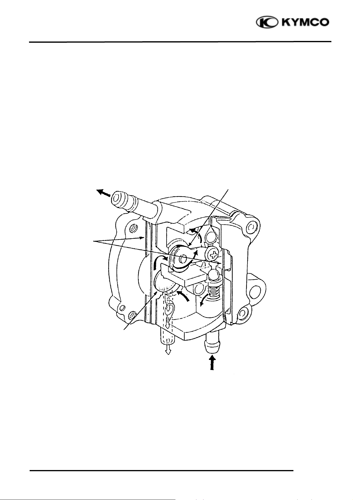
FUEL PUMP CONSTRUCTION
Diaphragms
Inlet
Outlet
Suction Valve
Outlet Valve
Pulsating Pressure
from Crankcase
Page 4
5. FUEL SYSTEM
5-3
FILLY LX 50
SERVICE INFORMATION
GENERAL INSTRUCTIONS
• When disassembling the carburetor, be sure to service the vacuum piston and float chamber.
• Do not bend or twist control cables. Damaged control cables will not operate smoothly.
• When disassembling fuel system parts, note the locations of O-rings. Replace them with new
ones during assembly.
• Before float chamber disassembly, loosen the drain screw to drain the residual gasoline into a
clean container.
• After the carburetor is removed, plug the intake manifold side with a clean shop towel to prevent
foreign matters from entering.
• Remove the vacuum diaphragm before cleaning the carburetor air and fuel passages with
compressed air to avoid damaging the vacuum diaphragm.
• When the motorcycle is not used for over one month, drain the residual gasoline from the float
chamber to avoid erratic idling and clogged slow jet due to deteriorated fuel.
SPECIFICATIONS
Item
Standard
Venturi dia. (mm)
20
Type
CVK
Float level (mm)
17
Main jet
#85
Slow jet
#35
Idle speed
1900rpm
Throttle grip free play
2_ 6mm
Pilot screw opening
2±
1
/2
Gasoline is very dangerous. When working with gasoline, keep sparks and flames away
from the working area.
Gasoline is extremely flammable and is explosive under certain conditions. Be sure to
work in a well-ventilated area.
SERVICE INFORMATION
......................
5-3 ACCELERATING PUMP
......................
5-11
TROUBLESHOOTING
.............................
5-4 CARBURETOR INSTALLATION
........
5-12
CARBURETOR REMOVAL
....................
5-5 PILOT SCREW ADJUSTMENT
............
5-13
AUTO BYSTARTER
.................................
5-5 FUEL TANK
...........................................
5-14
AIR CUT-OFF VALVE
.............................
5-7 AUTO FUEL VALVE
.............................
5-15
VACUUM CHAMBER
.............................
5-7 FUEL UNIT
.............................................
5-18
FLOAT CHAMBER
..................................
5-9 AIR CLEANER
........................................
5-18
Page 5

5. FUEL SYSTEM
5-4
FILLY LX 50
TROUBLESHOOTING
Engine is hard to start Misfiring during acceleration
• No spark at plug (!Section 15) • Faulty ignition system
• Compression too low • Lean mixture
• No fuel to carburetor • Faulty accelerating pump
-Clogged fuel filter Engine idles roughly, stalls or runs poorly
-Restricted fuel line • Clogged fuel system
-Faulty float valve • Ignition malfunction
-Incorrectly adjusted float level • Rich or lean mixture
• Engine flooded with fuel • Contaminated fuel
-Clogged air cleaner • Intake air leak
-Fuel overflowing • Incorrect idle speed
• Intake air leak • Incorrectly adjusted pilot screw
• Contaminated fuel • Clogged idle system or auto bystarter passages
• Faulty auto bystarter • Incorrectly adjusted float level
• Clogged idle system or auto bystarter passages Lean mixture
Rich mixture • Clogged fuel jets
• Faulty auto bystarter • Faulty float valve
• Faulty float valve • Float level too low
• Float level too high • Clogged fuel system
• Clogged air jets • Intake air leak
• Dirty air cleaner • Improper vacuum piston operation
• Flooded carburetor • Improper throttle operation
Backfiring at deceleration
• Lean mixture in idle system
• Improper air cut-off valve operation
Page 6
5. FUEL SYSTEM
5-5
FILLY LX 50
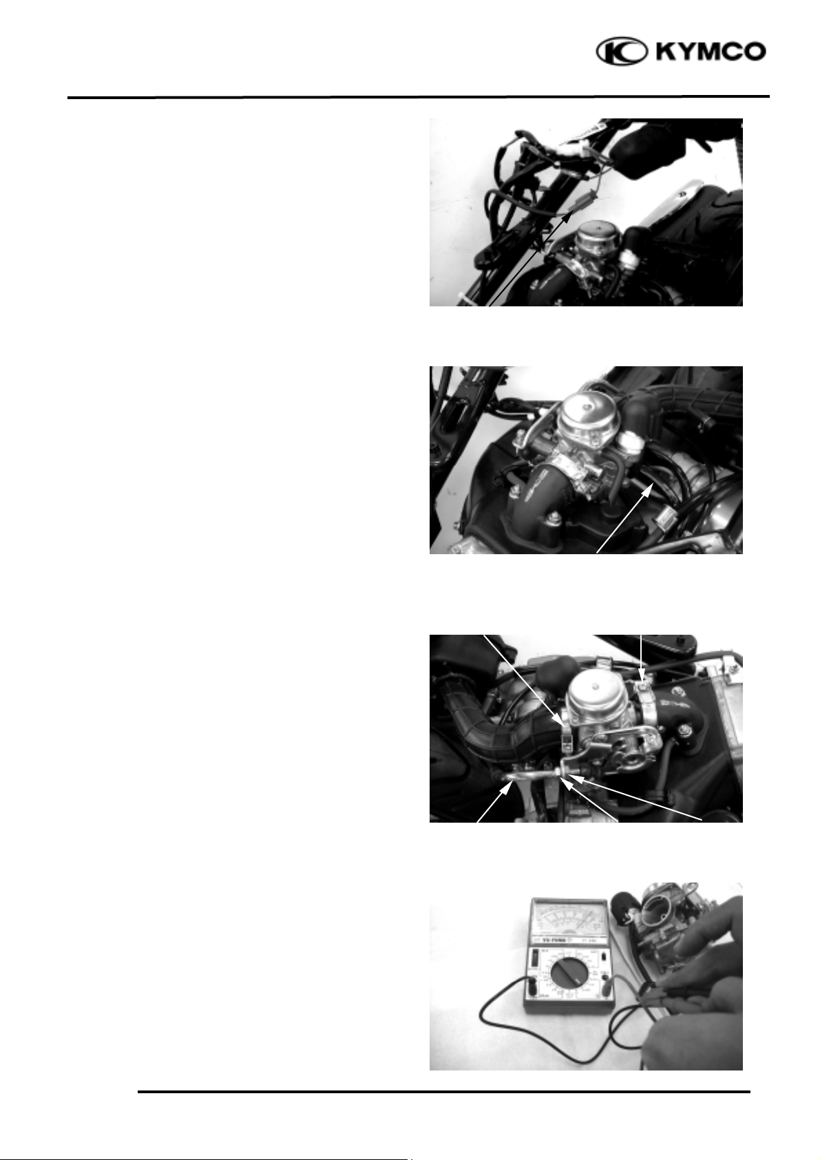
CARBURETOR REMOVAL
Remove the frame right side cover. (!2-4)
Disconnect the auto bystarter wire
connector.
Remove the met-in box. (!2-3)
Loosen the drain screw and drain the fuel
from the float chamber.
Disconnect the fuel tube and vacuum tube at
the carburetor.
Loosen the throttle cable adjusting nut and
lock nut, and disconnect the throttle cable
from the carburetor.
Loosen the carburetor intake manifold band
and air cleaner connecting tube band screws
and then remove the carburetor.
AUTO BYSTARTER
OPERATION INSPECTION
Measure the resistance between the auto
bystarter wire terminals.
Resistance: 10W max. (10 minutes
minimum after stopping the engine)
If the reading is not within the limit, replace
the auto bystarter with a new one.
Adjusting Nut
Fuel Tube
Intake Manifold
Band
Air Cleaner Connect ing
T ube Band
Throttle Cable
Lock Nut
Auto Bystarter Wire
Page 7

5. FUEL SYSTEM
5-6
FILLY LX 50
Connect a hose to the fuel enriching circuit
of the carburetor. Connect the auto
bystarter yellow wire to the positive (+)
terminal of a battery and green wire to the
negative (-) terminal. Wait 5 minutes and
blow the hose with mouth or vacuum pump.
If the passage is blocked, the auto bystarter
is normal.
Disconnect the auto bystarter from the
battery. Wait 30 minutes and blow the hose
with mouth or vacuum pump. If air can be
blown into the hose, the auto bystarter is
normal.
REMOVAL
Remove the set plate screws and set plate.
Remove the auto bystarter from the
carburetor.
AUTO BYSTARTER INSPECTION
Check the auto bystarter valve and needle
for nicks, wear or damage.
If any faulty part is found, replace the auto
bystarter as a set.
INSTALLATION
Insert the auto bystarter into the carburetor
body until it bottoms.
Position the set plate into the groove in the
auto bystarter and tighten the screws.
Auto Bystarter
Screws
Bystarter Needle
Bystarter Valve
Auto Bystarter
Screws
Set Plate
Vacuum Pump
Adopter
Set Plate
• Be sure to install the auto bystarter and
set plate properly.
• Install the set plate with its bottom
face facing down.
*
Page 8

5. FUEL SYSTEM
5-7
FILLY LX 50
AIR CUT-OFF VALVE
DISASSEMBLY
Remove the two screws attaching the
throttle cable set plate and the set plate.
Remove the two screws attaching the air
cut-off valve.
Remove the spring and vacuum diaphragm.
Check the vacuum diaphragm for cracks or
damage and check each passage for clogging.
ASSEMBLY
Install the vacuum diaphragm onto the
carburetor.
Install the spring and air cut-off valve cover.
Install the throttle cable set plate and tighten
the two screws.
VACUUM CHAMBER
DISASSEMBLY
Remove the two vacuum chamber cover
screws and the cover.
Remove the spring and vacuum diaphragm/
piston.
Spring
Spring
Throttle Cable Set
Vacuum Diaphragm/Piston
Air Cut-off Valve Cover
Cover
Screws
O-ring
Screws
Screws
• Be sure to set the vacuum diaphragm
lip into the groove on the carburetor.
• When installing the air cut-off valve
cover, make sure that the vacuum
diaphragm is properly installed.
*
Diaphragm
Vacuum Chamber Cover
Spring
Page 9

5. FUEL SYSTEM
5-8
FILLY LX 50
Remove the needle holder and jet needle.
INSPECTION
Inspect the needle for stepped wear.
Inspect the vacuum piston for wear or
damage.
Inspect the diaphragm for deterioration and
tears.
ASS EMBLY
Install the vacuum piston/diaphragm in the
carburetor body.
Install the spring and then install the
vacuum chamber cover.
Tighten the two screws.
Vacuum Chamber Cover
Vacuum Diaphragm
Jet Needle
Vacuum Diaphragm
Be careful not to damage the vacuum
diaphragm.
*
• Be careful not to damage the diaphragm.
• Hold the vacuum piston while
tightening the vacuum chamber cover.
*
Page 10

5. FUEL SYSTEM
5-9
FILLY LX 50
FLOAT CHAMBER
DIS AS SEMBLY
Remove the three float chamber screws and
the float chamber.
Loosen the float pin screw.
Remove the float pin, float and float valve.
Remove the main jet, needle jet holder,
needle jet, slow jet and pilot screw.
Clean the removed fuel jets with detergent
oil and blow them open with compressed
air.
Blow compressed air through all passages of
the carburetor body.
Pilot Screw
Float Valve
Float
Float Pin
Float Chamber
Slow Jet
Main Jet
Needle Jet Holder
Needle Jet
Screws
• Be careful not to damage the fuel jets
and pilot screw.
• Before removing, turn the pilot screw
in and carefully count the number of
turns until it seats lightly and then
make a note of this.
• Do not force the pilot screw against its
seat to avoid seat damage.
*
Page 11

5. FUEL SYSTEM
5-10
FILLY LX 50
INSPECTION
Inspect the float valve and valve seat for
damage or clogging.
Inspect the float valve and valve seat
contact area for stepped wear or
contamination.
ASSEMBLY
Install the slow jet, needle jet, needle jet
holder, main jet and pilot screw.
Standard Opening: 2±
1
/2
turns
Install the float valve, float and float pin.
Secure the float pin with the screw.
FLOAT LEVEL INSPECTION
Measure the float level.
Float Level: 17.0mm
This installation sequence is the reverse of
removal.
Float Level Gauge
Float Valve
• Check the operation of the float valve
and float before this inspection.
• Measure the float level by placing the
float level gauge on the float chamber
face parallel with the main jet.
*
Float Pin
Pilot Screw
Slow Jet
Main Jet
Needle Jet Holder
Needle Jet
Valve Seat
Float
Screw
Worn or contaminated float valve and
valve seat must be replaced because it
will result in float level too high due to
incomplete airtightness.
*
Return the pilot screw to the original
position as noted during removal.
*
Page 12

5. FUEL SYSTEM
5-11
FILLY LX 50
ACCELERATING PUMP
DISASSEMBLY
Remove the two accelerating pump cover
screws and accelerating pump cover.
Remove the spring and accelerating pump
diaphragm.
INSPECTION
Inspect the accelerating pump diaphragm for
cracks, damage or deterioration. Replace if
necessary.
Check each accelerating pump fuel passage
for clogging
Clean and blow them open with compressed
air.
Install the accelerating pump in the reverse
order of removal.
Compressed Air
Screws
Diaphragm
Diaphragm
Compressed Air
Be careful not to damage the diaphragm
during installation.
*
Page 13

5. FUEL SYSTEM
5-12
FILLY LX 50
CARBURETOR INSTALLATION
Tighten the drain screw.
Install the carburetor onto the intake
manifold, aligning the tab on the carburetor
with the cutout in the intake manifold.
Tighten the intake manifold band screw.
Install the air cleaner connecting tube and
tighten the band screw.
Connect the throttle cable to the throttle
wheel on the carburetor.
Tighten the lock nut.
Connect the fuel tube and vacuum tube to
the carburetor.
Connect the auto bystarter wire connector.
Perform the following inspections and
adjustments:
-Throttle grip free play (!3-3)
-Carburetor idle speed (!3-5)
Auto Bystarter Wire
Fuel Tube
Connecting Tube Band
Throttle Cable
Throttle Cable
Lock Nut
Adjusting Nut
Page 14

5. FUEL SYSTEM
5-13
FILLY LX 50
PILOT SCREW ADJUSTMENT
*
ADJUSTMENT
A tachometer must be used when adjusting
the engine speed.
Turn the pilot screw clockwise until it seats
lightly and back it out to the specification
given.
Standard Opening: 2±
1
/2
turns
Warm up the engine and adjust the throttle
stop screw to obtain the specified idle
speed.
Idle Speed: 1900± 100rpm
Turn the pilot screw in or out slowly to
obtain the highest engine speed.
Slightly accelerate several times to make
sure that the idle speed is within the
specified range.
If the engine misses or runs erratic, repeat
the above steps.
Pilot Screw
Throttle Stop Screw
• The pilot screw is factory pre-set and
no adjustment is necessary. During
carburetor disassembly, note the
number of turns of the pilot screw and
use as a reference when reinstalling it.
• Place the motorcycle on its main stand
on level ground for this operation.
*
• The carburetor must be adjusted when
the engine is warm and the auto
bystarter is closed.
• Do not force the pilot screw against its
seat to prevent damage.
*
Page 15

5. FUEL SYSTEM
5-14
FILLY LX 50
FUEL TANK REMOVE
Remove the net-in box. (!2-3)
Remove the frame center cover.
Remove the frame body cover. (!2-3)
Remove the floor board. (!2-4)
Remove the leg shield . (!2-5)
Remove the four bolts on the fuel tank, take
the upper bridge plate off.
Remove the fuel tube between the fuel tank
and the fuel filler.
Disconnect the fuel vapor tube.
Remove the inlet tube on the fuel pump.
Disconnect the fuel unit wire connector.
Remove the fuel tank.
The installation sequence is the reverse of
removal.
FUEL STRAINER REMOVAL
Remove the fuel strainer from the fuel tank.
INSPECTION
Inspect if the fuel strainer is clogged and
clean it with compressed air.
INSTALLATION
Install the fuel strainer with its arrow mark
toward the fuel pump.
Fuel Unit Wire
Connector
Bolts
Fuel
Pump
• When removing the fuel strainer, do not
allow flames or sparks near the
working area and drain the residual
gasoline into a container.
*
Bridge
Plate
Fuel Vapor
Tube
Arrow Mark
Fuel Strainer
Inlet
Tube
Fuel
Tank
Page 16

5. FUEL SYSTEM
5-15
FILLY LX 50
FUEL PUMP REMOVAL
Remove the met-box. (!2-3)
Remove the frame center cover. (!2-3)
Remove the floor board. (!2-4)
Disconnect the fuel pump inlet, outlet and
vacuum tubes.
Remove the fuel pump attaching bolts and
the fuel pump.
Remove the fuel pump.
FUEL PUMP DISASSEMBLY
Remove the four fuel pump body screws.
Disassemble the fuel pump.
Retainer
Fuel Pump
Inlet
Screws
Vacuum Tube
Outlet
Nut
Page 17

5. FUEL SYSTEM
5-16
FILLY LX 50
FUEL PUMP INSPECTION
Inspect the fuel pump diaphragms A and B
for damage.
Inspect each gasket for damage.
Inspect the suction valve, outlet valve and
relief valve in the fuel pump body for
damage, cracks or foreign matters.
FUEL PUMP ASSEMBLY
Assemble the fuel pump in the reverse order
of disassembly.
Diaphragm A
Gaskets
Inlet
Spring
Suction Valve
Outlet Valve
Relief Valve
Outlet
Diaphragm B
Dowel Pins
Dowel Pin Holes
Fuel Pump Body
• During assembly, be sure to install the
gaskets and diaphragms properly to
avoid damage.
• Do not allow any foreign matter to
enter the fuel pump during assembly.
*
Page 18

5. FUEL SYSTEM
5-17
FILLY LX 50
FUEL PUMP INSTALLATION
Install the fuel pump and secure it with the
bolts.
Connect the fuel pump inlet, outlet and
vacuum tubes.
Install the floor board, met-in box and frame
center cover.
MEASURE THE FUEL PUMP
OUTPUT
Start the engine and disconnect the fuel
outlet tube and place a clean container under
the tube to check the fuel output.
Output: 9cc/1700rpm/10 seconds .
22cc/4000rpm/10 seconds .
Fuel Pump
Outlet Tube
Container
Fuel Pump
Page 19

5. FUEL SYSTEM
5-18
FILLY LX 50
FUEL UNIT
REMOVAL
Remove the related parts.
Disconnect the fuel unit wire connector.
Turn the fixed plate on the fuel unit left,take
the fuel unit off.
INSTALLATION
Inspet if the fuel unit is damaged,or harden.
Assemble the fuel unit in the reverse order
of disassembly.
AIR CLEANER
Loosen the air cleaner connecting tube band
screw.
Disconnect the clinhead cover breather tube
from the air cleaner.
Remove the two bolts and air cleaner case.
Fuel Unit Wire
Align Mark
Fuel Unit
Fuel Tank
Do not bend the float arm on the fuel
unit,otherwise the figure on the fuel
meter will not correct.
*
• Align the groove on the fuel unit with
the angle on the fuel tank.
• Inspect if the fuel tank leaked after
installing and filling the gasoling.
*
bolts
air cleaner
Page 20

5. FUEL SYSTEM
5-19
FILLY LX 50
The installation sequence is the reverse of removal.
 Loading...