

Page 1
12. FRONT WHEEL/FRONT BRAKE/
FRONT SUSPENSION
12-0
FILLY LX 50
12
12
Page 2
12. FRONT WHEEL/FRONT BRAKE/
FRONT SUSPENSION
12-1
FILLY LX 50
SERVICE INFORMATION
GENERAL INSTRUCTIONS
• Remove the motorcycle frame covers before removing the front wheel. Jack the motorcycle front
wheel off the ground and be careful to prevent the motorcycle from falling down.
• During servicing, keep oil or grease off the brake drum and brake linings.
SPECIFICATIONS
Item
Standard (mm)
Service Limit (mm)
Axle shaft runout
æ
0.2
Radialæ2.0
Front wheel rim runout
Axialæ2.0
Front brake drum I.D
110(SG20AB)
111(SG20AB)
Front brake lining thickness
4.0(SG20AB)
2.0(SG20AB)
Front shock absorber spring free length
210.9
206.4
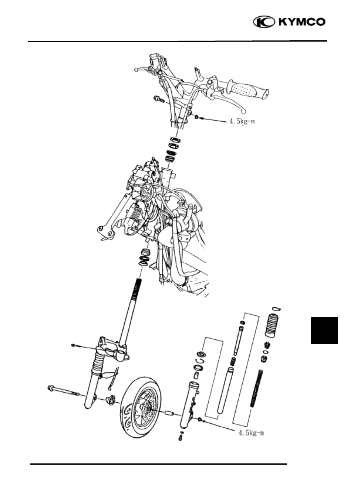
TORQUE VALUES
Handlebar bolt 4.5~5.5kgf-m
Steering stem lock nut 6.0~8.0kgf-m
Steering top cone race 0.5~1.3kgf-m
Front shock absorber bolt 3.0kgf-m
Front axle nut 5.0~7.0kgf-m
Brake arm bolt 0.8~1.2kgf-m
SPECIAL TOOLS
Long socket wrench,32mm 8angle
SERVICE INFORMATION
....................
12-1 FRONT BRAKE
.....................................
12- 7
TROUBLESHOOTING
..........................
12-2 FRONT SHOCK ABSORBER
...............
12-18
STEERING HANDLEBAR
.....................
12-3 FRONT FORK
........................................
12-21
FRONT WHEEL
......................................
12-4
Page 3

12. FRONT WHEEL/FRONT BRAKE/
FRONT SUSPENSION
12-2
FILLY LX 50
TROUBLESHOOTING
Hard steering (heavy) Front wheel wobbling
• Excessively tightened steering stem top • Bent rim
cone race
• Excessive wheel bearing play
• Broken steering balls • Bent spoke plate
• Insufficient tire pressure • Faulty tire
Steers to one side or does not track straight • Improperly tightened axle nut
• Uneven front shock absorbers Soft front shock absorber
• Bent front fork • Weak shock springs
• Bent front axle or uneven tire • Insufficient damper oil
Poor brake performance Front shock absorber noise
• Incorrectly adjusted brake • Slider bending
• Worn brake linings • Loose fork fasteners
• Contaminated brake lining surface • Lack of lubrication
• Worn brake shoes at cam contacting area
• Worn brake drum
• Poorly connected brake arm
Page 4
12. FRONT WHEEL/FRONT BRAKE/
FRONT SUSPENSION
12-3
FILLY LX 50
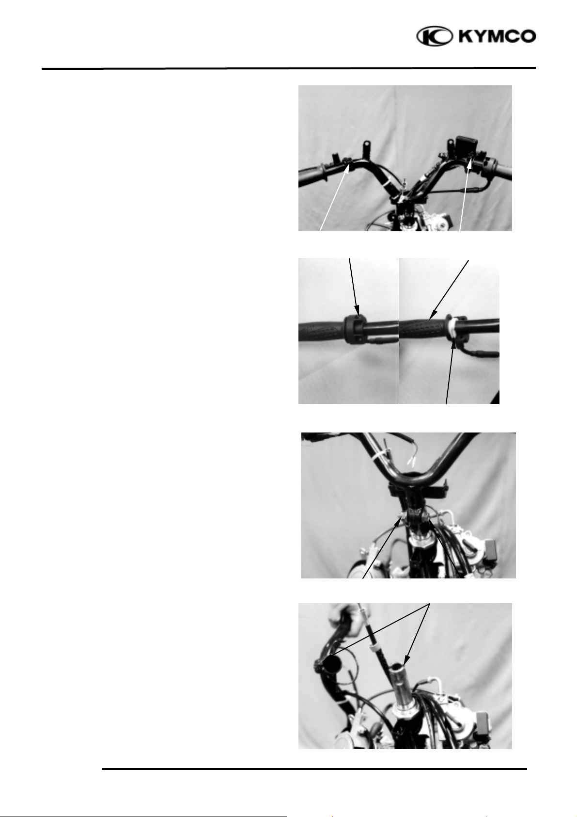
STEERING HANDLEBAR
REMOVAL
Remove the handlebar front and rear covers.
(!2-2)
Remove the two bolts attaching each of the
front and rear brake levers.
Remove the front and rear brake levers.
Remove the two throttle holder screws and
throttle holder.
Disconnect the throttle cable from the throttle
pipe and then remove the throttle pipe from
the handlebar.
Remove the handlebar lock nut and bolt to
remove the handlebar.
INSTALLATION
Install the handlebar onto the steering stem
by aligning the tab on the handlebar with the
groove on the steering stem.
Install and tighten the handlebar bolt and lock
nut.
Torque: 4.5_ 5.5kgf-m
Screws
Bolts
Throttle Pipe
Throttle
Bolts
Nut
Tab/Groove
Bolt
Page 5
12. FRONT WHEEL/FRONT BRAKE/
FRONT SUSPENSION
12-4
FILLY LX 50
Apply grease to the tip of the throttle pipe.
Install the throttle pipe and connect the
throttle cable.
Install the front and rear brake levers in the
reverse order of removal.
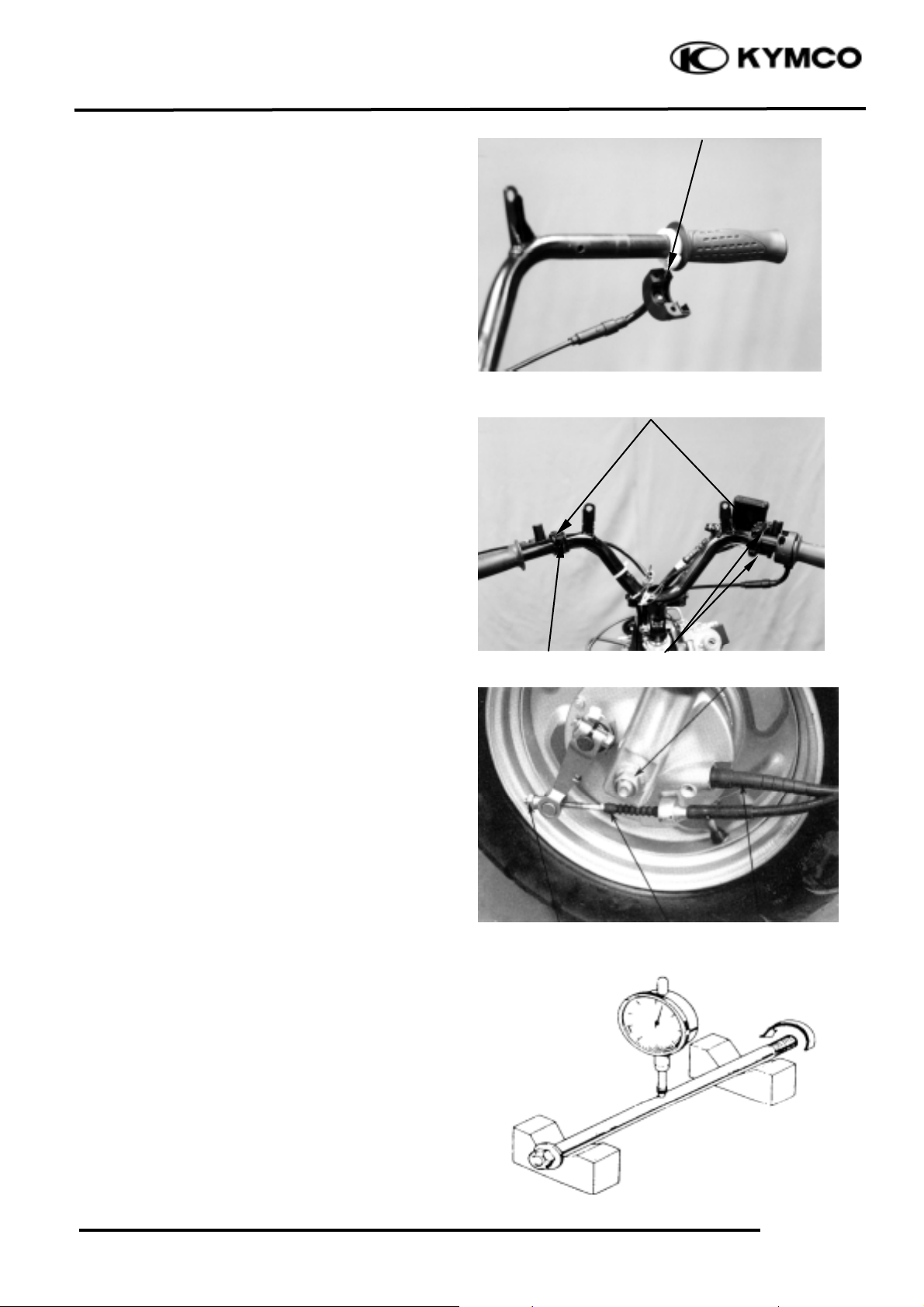
FRONT WHEEL
REMOVAL
Jack the motorcycle front wheel off the
ground.
Remove the speedometer cable set screw and
disconnect the speedometer cable.
Remove the front brake cable.
Remove the front axle nut and pull out the
axle.
Remove the front wheel.
Remove the front brake panel and side collar.
INSPECTION
AXLE RUNOUT
Set the axle in V blocks and measure the
runout using a dial gauge.
The actual runout is
1
/2
of the total indicator
reading.
Service Limit: 0.2mm replace if over
Brake Levers
Speedometer Cable
Brake Cable
Axle Nut
Adjusting Nut
Throttle
Bolts
Bolts
Page 6
12. FRONT WHEEL/FRONT BRAKE/
FRONT SUSPENSION
12-5
FILLY LX 50
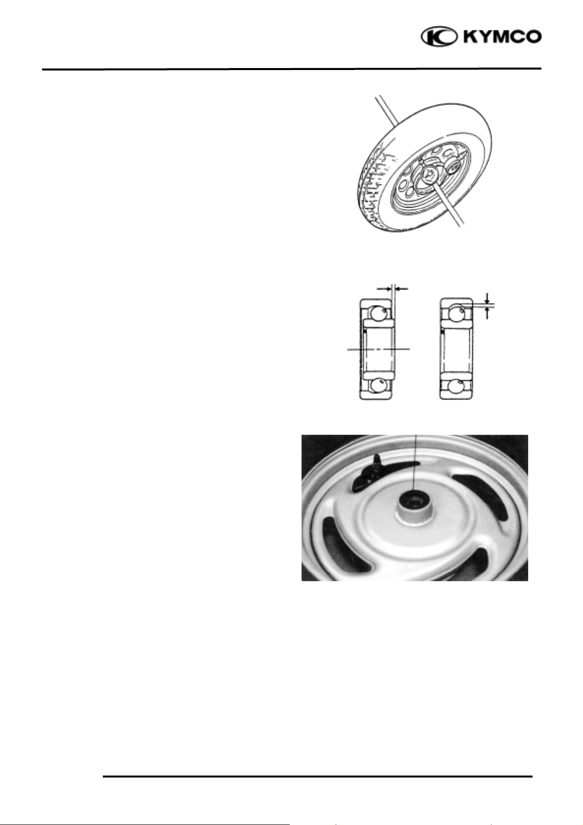
WHEEL RIM
Check the wheel rim runout.
Service Limits:
Radial: 2.0mm replace if over
Axial: 2.0mm replace if over
Turn the wheel bearings and replace the
bearings if they are noisy or have excessive
play.
DISASSEMBLY
Remove the dust seal.
Radial
Dust Seal
Play
Play
Axial
Page 7
12. FRONT WHEEL/FRONT BRAKE/
FRONT SUSPENSION
12-6
FILLY LX 50
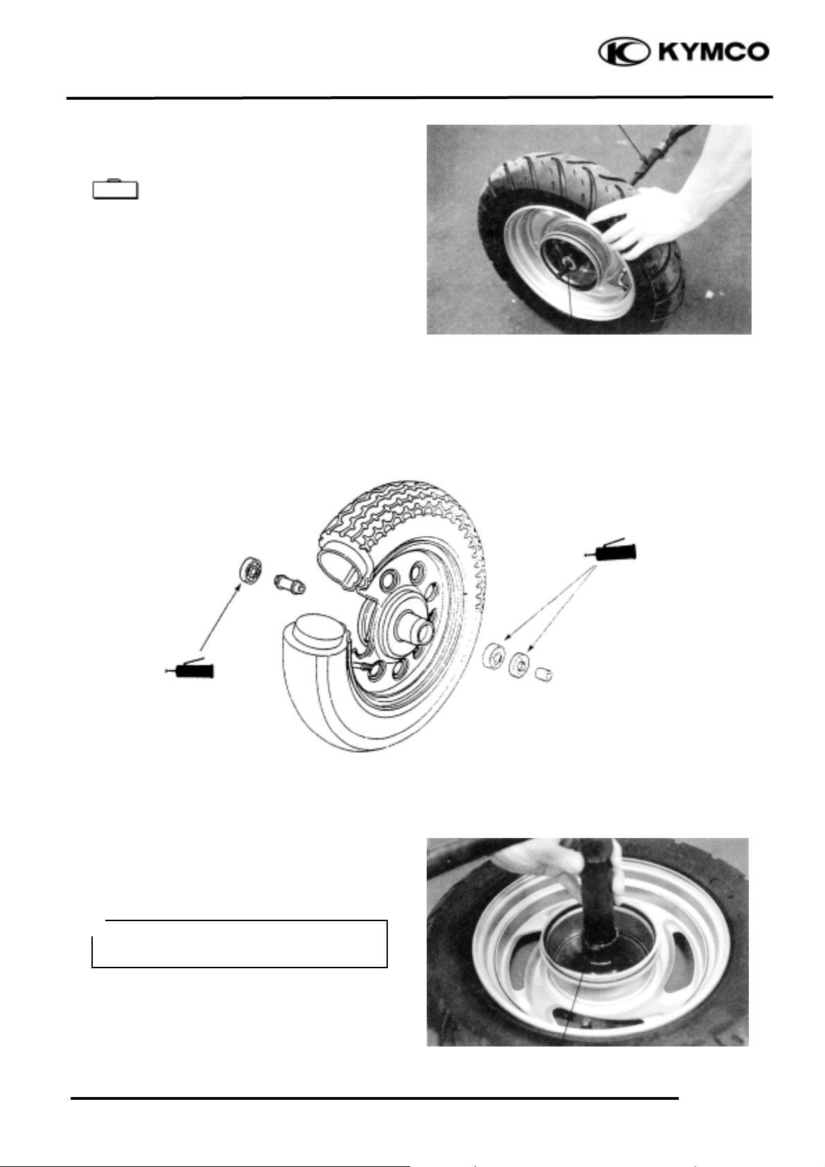
Remove the front wheel bearings and distance
collar.
Bearing Puller
ASSEMBLY
Pack all bearing cavities with grease.
Drive in the left bearing.
Install the distance collar.
Drive in the right bearing.
Bearing Puller
Pilot
Grease
Grease
Outer Driver
Pilot
Drive in the bearing squarely with the
sealed end facing out.
*
Special
Page 8

12. FRONT WHEEL/FRONT BRAKE/
FRONT SUSPENSION
12-7
FILLY LX 50
Apply grease to a new dust seal lip and
install the dust seal.
Install the side collar.
INSTALLATION
Install the front wheel by aligning the brake
panel groove with the front fork tab.
Insert the axle shaft and tighten the axle nut.
Torque: 4.5kg-m
Connect the speedometer cable and secure it
with the screw.
Install the front brake cable and adjust the
front brake lever free play.
FRONT BRAKE
Remove the front wheel. (!12-4)
Remove the front brake panel.
INSPECTION
Measure the brake drum I.D.
Service Limit: 111mm replace if over
Measure each brake lining thickness.
Service Limit: 2.00mmmm replace if below
Groove
Keep oil or grease off the brake linings.
*
Tab
Dust Seal
Side Collar
Brake Linings
Brake Shoe Springs
Brake Cam
Page 9

12. FRONT WHEEL/FRONT BRAKE/
FRONT SUSPENSION
12-8
FILLY LX 50
DISASSEMBLY
Do not swing the brake arm to expand the
brake shoes.
Remove the brake shoes by removing the
brake shoe springs using a screw driver.
Remove the brake arm and return spring.
Remove the wear indicator plate and felt seal.
Remove the brake cam.
Remove the dust seal and speedometer drive
gear.
ASSEMBLY
Apply grease to the speedometer drive gear
and then install it into the brake panel.
Apply grease to the dust seal lip and install it
into the brake panel.
Apply grease to the anchor pin and brake
cam.
Install the brake cam.
Brake Shoe
Speedometer Drive Gear
Dust Seal
Brake Arm
Brake Cam
Anchor Pin
Felt Seal
Return Spring
Brake Cam
1.0kg-m
Wear Indicator Plate
Speedometer Drive Gear
Dust Seal
Grease
Grease
Page 10

12. FRONT WHEEL/FRONT BRAKE/
FRONT SUSPENSION
12-9
FILLY LX 50
Install the return spring by aligning the spring
hook end with the hole in the brake panel.
Apply a small amount of engine oil to the felt
seal and install it to the brake panel.
Install the wear indicator plate on the brake
cam by aligning the tooth on the plate with
the groove on the brake cam.
Install the brake arm on the brake cam by
aligning the punch mark on the brake arm and
the scribed line on the brake cam.
Install and tighten the brake arm bolt.
Torque:0.8~1.2kgf-m
Install the brake shoe springs to the brake
shoes and then install the brake shoes into the
brake panel.
INSTALLATION
Install the brake panel onto the front wheel.
Install the front wheel. (!12-7)
Adjust the front brake lever free play.
Brake Arm
Wear Indicator Plate
Return Spring
Brake Shoe Springs
Brake Cam
Bolt
Brake Shoes
Page 11

12. FRONT WHEEL/FRONT BRAKE/
FRONT SUSPENSION
12-10
FILLY LX 50
HYDRAULIC BRAKE (FRONT BRAKE)
Brake Fluid Replacement/Air Bleeding
Check the brake fluid level on level ground.
Brake Fluid Bleeding
In order to avoid spill of brake fluid, connect
a transparent hose to the bleed valve.
Fully apply the brake lever and then loosen
the brake caliper bleed valve to drain the
brake fluid until there is no air bubbles in the
brake fluid. Then, tighten the bleed valve.
Repeat these steps until the brake system is
free of air.
Brake Fluid Refilling
Add DOT-4 brake fluid to the brake
reservoir.
Make sure to bleed air from the brake system.
• When operating the brake lever, the
brake reservoir cap must be tightened
securely to avoid spill of brake fluid.
• When servicing the brake system, use
shop towels to cover plastic parts and
coated surfaces to avoid damage
caused by spill of brake fluid.
*
Brake fluid spilled on brake pads or
brake disk will reduce the braking effect.
Clean the brake pads and brake disk
with a high quality brake degreaser.
Warning
• When bleeding, be careful not to allow
air in the brake reservoir flowing into
the brake system.
• When using a brake bleeder, follow the
manufacturer‘s instructions.
• Never use dirty or unspecified brake
fluid or mix different brake fluids because it will damage the brake system.
*
Upper Limit
Lower Limit
Bleed Valve
Front Brake Caliper
Page 12

12. FRONT WHEEL/FRONT BRAKE/
FRONT SUSPENSION
12-11
FILLY LX 50
Brake Pad/Disk Replacement
Remove the two bolts attaching the brake
caliper.
Remove the brake caliper.
Remove the brake pad pins to remove the
brake pads.
Install the brake pads in the reverse order of
removal.
Tighten the brake pad pin bolts.
Torque: 1.5_ 2.0kgf-m
Brake Disk
Measure the brake disk thickness.
Service Limit: 3.0mm
Measure the brake disk runout.
Service Limit: 0.3mm
The brake pads must be replaced as a
set to ensure the balance of the brake
disk.
*
_Keep grease or oil off the brake pads
to avoid brake failure.
_Do not reuse the brake pad pin bolts
that have been removed.
*
Pad Pin
Front Brake Caliper
Brake Pads
Front Brake Caliper
Page 13

12. FRONT WHEEL/FRONT BRAKE/
FRONT SUSPENSION
12-12
FILLY LX 50
BRAKE MASTER CYLINDER
Removal
First drain the brake fluid from the hydraulic
brake system.
Disassembly
Remove the piston rubber cover and snap ring
from the brake master cylinder.
Remove the washer, main piston and spring
from the brake master cylinder.
Clean the inside of the master cylinder and
brake reservoir with brake fluid.
• When servicing the brake system, use
shop towels to cover rubber and
plastic parts and coated surfaces to
avoid being contaminated by brake
fluid.
• When removing the brake fluid pipe
bolt, be sure to plug the pipe to avoid
*
Bolts
Brake Master Cylinder
Snap Ring
Main Piston
Spring
Master Cylinder
Snap Ring
Washer
Page 14

12. FRONT WHEEL/FRONT BRAKE/
FRONT SUSPENSION
12-13
FILLY LX 50
Inspection
Measure the brake master cylinder I.D.
Service Limit: 12.75mm
Inspect the master cylinder for scratch or
crack.
Measure the brake master cylinder piston
O.D.
Service Limit: 12.6mm
Before assembly, inspect the lst and 2nd
rubber cups for wear.
Assembly
Before assembly, apply brake fluid to all
removed parts.
Install the spring together with the 1st rubber
cup.
Install the main piston, spring and snap ring.
Install the rubber cover.
Install the brake lever.
• During assembly, the main piston and
spring must be installed as a unit
without exchange.
• When assembling the piston, soak the
cups in brake fluid for a while.
• Install the cups with the cup lips
facing the correct direction.
*
Page 15

12. FRONT WHEEL/FRONT BRAKE/
FRONT SUSPENSION
12-14
FILLY LX 50
Disassembly
Remove the brake caliper seat from the brake
caliper.
Remove the piston from the brake caliper.
If necessary, use compressed air to squeeze
out the piston through the brake fluid inlet
opening and place a shop towel under the
caliper to avoid contamination caused by the
removed piston.
Check the piston cylinder for scratch or wear
and replace if necessary.
Push the piston oil seal outward to remove it.
Clean the oil seal groove with brake fluid.
Be careful not to damage the piston
surface.
*
Brake Caliper Seat
Compressed Air
Piston Oil Seal
Page 16

12. FRONT WHEEL/FRONT BRAKE/
FRONT SUSPENSION
12-15
FILLY LX 50
Place the brake master cylinder on the
handlebar and install the holder with “up”
mark facing up. Be sure to align the punch
mark with the holder joint.
First tighten the upper bolt and then tighten
the lower bolt.
Torque: 3.0_ 4.0kgf-m
Install the brake fluid pipe with the attaching
bolt and two sealing washers.
Install the handlebar covers. (!12-3)
Fill the brake reservoir with recommended
brake fluid to the upper limit and bleed air
according to the method stated in 12-10.
BRAKE CALIPER (FRONT)
Removal
Remove the brake caliper.
Place a clean container under the brake caliper
and disconnect the brake fluid pipe from the
caliper.
Do not spill brake fluid on any coated
surfaces.
*
Punch Mark
Bolts
“Up” Mark
Bolt
Bleed Valve
Bleed Valve
Brake Caliper
Page 17

12. FRONT WHEEL/FRONT BRAKE/
FRONT SUSPENSION
12-16
FILLY LX 50
Check the piston for scratch or wear.
Measure the piston O.D. with a micrometer.
Service Limit: 26.3mm
Check the caliper cylinder for scratch or wear
and measure the cylinder bore.
Service Limit: 26.45mm
Assembly
Clean all removed parts.
Apply silicon grease to the piston and oil
seal. Lubricate the brake caliper cylinder
inside wall with brake fluid.
Install the brake caliper piston with grooved
side facing out.
Wipe off excessive brake fluid with a clean
shop towel. Apply silicon grease to the
brake caliper seat pin and caliper inside.
Install the brake caliper seat.
Install the piston with its outer end
3_ 5mm protruding beyond the brake
caliper.
*
Page 18

12. FRONT WHEEL/FRONT BRAKE/
FRONT SUSPENSION
12-17
FILLY LX 50
Installation
Install the brake caliper and tighten the two
bolts.
Torque: 2.9_ 3.5kg-m
Connect the brake fluid pipe to the brake
caliper and tighten the fluid pipe bolt.
Torque: 2.5_ 3.5kg-m
Fill the brake reservoir with recommended
brake fluid and bleed air from the brake syst
em. (!12-10)
Bolts
Bolt
Page 19

12. FRONT WHEEL/FRONT BRAKE/
FRONT SUSPENSION
12-18
FILLY LX 50
FRONT SHOCK ABSORBER
REMOVAL
Remove the front wheel. (!12-4)
Remove the front lower cover. (!2-2)
Remove the front inner fender.
Remove the front shock absorber upper
mount bolts.
Loosen the lower mount bolts to remove the
front shock absorbers.
DISASSEMBLY
Remove the dust boot.
Remove the circlip.
Set the front shock absorber in a vise.
Remove the damper rod, hex bolt and copper
washer.
Pull out the front shock absorber tube.
Set the front shock absorber tube in a vise.
Remove the top nut, shock spring, damper,
and damper spring from the front shock
absorber tube.
Shock Absorber Tube
Washer/Bolt
Circlip
Shock Absorber
Dust Boot
• When holding the shock absorber tube,
place a shop towel to protect it and do
apply too much force .
*
Upper Mount Bolts
Front Shock Absorber
Lower Mount Bolts
Page 20

12. FRONT WHEEL/FRONT BRAKE/
FRONT SUSPENSION
12-19
FILLY LX 50
Measure the front shock absorber spring free
length.
Service Limits: Right : 206.4mm
Left : 206.4mm
ASSEMBLY
Front Shock
Absorber
Shock
Absorber
Tube
Top Nut
Damper
Shock Absorber
Spring
Damper
Spring
Dust Seal
Circlip
Oil Seal
Page 21

12. FRONT WHEEL/FRONT BRAKE/
FRONT SUSPENSION
12-20
FILLY LX 50
Install the damper spring onto the damper rod
and then install them into the front shock
absorber tube.
Install the shock absorber spring onto the
front shock absorber tube and tighten the top
nut.
Set the front shock absorber in a vise.
Insert the shock absorber tube into the shock
absorber and tighten the hex bolt.
(Apply locking agent to the washer and
install it together with the hex bolt.)
Torque: 3.0kgf-m
Add engine oil into the front shock absorber.
Specified Oil: SS#8
Oil Capacity: 38±1cc
Install the circlip.
Install the dust boot.
INSTALLATION
Install the front shock absorbers onto the
steering stem.
Install and tighten the front shock absorber
upper mount bolts.
Tighten the lower mount bolts.
Install the front wheel. (!12-7)
Circlip
Dust Boot
Install the front shock absorber spring
with the closely wound coils facing down.
*
Align the upper mount bolt hole with
the groove on the front fork.
*
Front Shock Absorber
Shock Absorber Tube
Upper Mount Bolts
Lower Mount Bolts
Page 22

12. FRONT WHEEL/FRONT BRAKE/
FRONT SUSPENSION
12-21
FILLY LX 50
FRONT FORK
REMOVAL
Remove the steering handlebar. (!12-3)
Remove the front wheel. (!12-4)
Disconnect the speedometer cable.
Remove the steering stem lock nut using long
socket wrench.
Long Socket Wrench,32mm 8Angle
Remove the top cone race and remove the
steering stem.
Inspect the ball races and cone races for wear
or damage and replace if necessary.
.
BOTTOM CONE RACE REPLACEMENT
Remove the bottom cone race using a chisel.
Drive a new bottom cone race into place with
a proper driver.
BALL RACE REPLACEMENT
Drive out the top and bottom ball races.
Top Cone Race
Long Socket Wrench
• Be careful not to lose the steel balls (26
on top race and 29 on bottom race).
*
Be careful not to damage the steering
stem and front fork.
*
Bottom Cone Race
Ball Race Remover
Lock Nut Wrench
Specia
Page 23

12. FRONT WHEEL/FRONT BRAKE/
FRONT SUSPENSION
12-22
FILLY LX 50
Drive new top and bottom ball races into the
steering head using the outer driver.
INSTALLATION
Apply grease to the top and bottom ball races
and install 26 steel balls on the top ball race
and 29 steel balls on the bottom ball race.
Apply grease to the ball races and install the
front fork.
Apply grease to the top cone race and install
it.
Tighten the top cone race and then turn the
steering stem right and left several times to
make steel balls contact each other closely.
Install the steering stem lock nut and tighten
it while holding the top cone race.
Torque: 6.0_ 8.0kgf-m
Install the front wheel. (!12-7)
Install the steering handlebar. (!12-3)
Install the speedometer cable. (!12-7)
Long Socket Wrench,32mm 8Angle
Top Cone Race
Outer Driver, 37x40mm
Check that the steering stem rotates
freely without vertical play.
*
Lock Nut Wrench
Driver Handle A
Be sure to completely drive in the ball
races.
*
Steel Balls
Long Socket Wrench
Specia
 Loading...