

Page 1
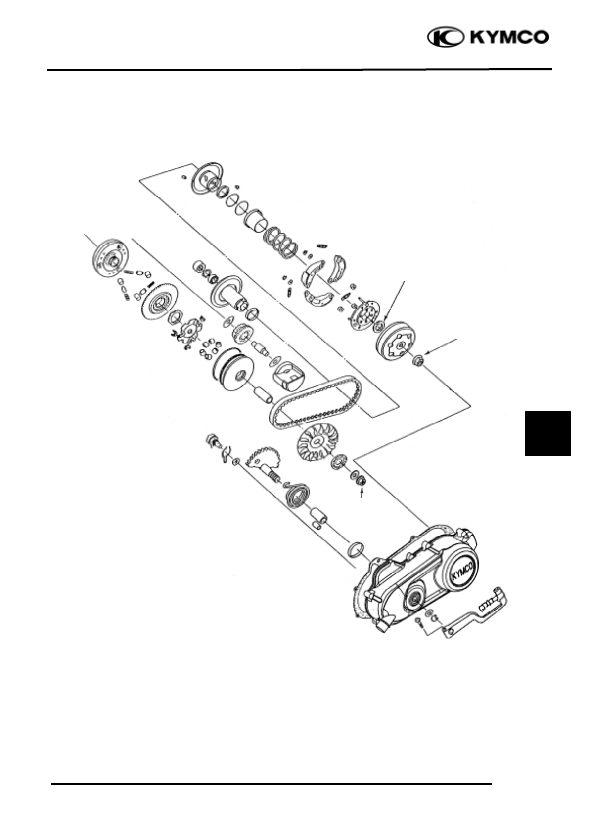
9. DRIVE AND DRIVEN PULLEYS/
KICK STARTER
9-0
FILLY LX 50
9
9
5.0_ 6.0kg-m
3.5-4.5g-m
3.5-4.0g-m
Page 2
9. DRIVE AND DRIVEN PULLEYS/
KICK STARTER
9-1
FILLY LX 50
SERVICE INFORMATION
GENERAL INSTRUCTIONS
• The drive pulley, clutch and driven pulley can be serviced with the engine installed.
• Avoid getting grease and oil on the drive belt and pulley faces. Remove any oil or grease from
them to minimize the slipping of drive belt and drive pulley.
SPECIFICATIONS
Item
Standard (mm)
Service Limit (mm)
Movable drive face bushing I.D.
23.989~24.025
24.06
Drive face collar O.D.
23.960~23.974
23.94
Drive belt width
17.5
16.5
Clutch lining thickness
æ
1.5
Clutch outer I.D.
107.0-107.2
107.5
Driven face spring free length
æ
154.6
Driven face O.D.
33.965-33.485
33.94
Movable driven face I.D.
34.0-34.025
34.06
Weight roller O.D.
15.920~16.080
15.4
TORQUE VALUES
Drive face nut 5.5~6.5kgf-m
Clutch outer nut 3.5~4.5kgf-m
Clutch drive plate nut 5.0-6.0kg-m
SPECIAL TOOLS
Universal holder Clutch spring compressor
TROUBLESHOOTING
Engine starts but motorcycle won‘t move Lack of power
• Worn drive belt • Worn drive belt
• Broken ramp plate • Weak driven face spring
• Worn or damaged clutch lining • Worn weight roller
• Broken driven face spring • Fouled drive face
Engine stalls or motorcycle creeps
• Broken clutch weight spring
SERVICE INFORMATION
......................
9-1 DRIVE BELT
...........................................
9-5
TROUBLESHOOTING
.............................
9-1 DRIVE PULLEY
......................................
9-6
LEFT CRANKCASE COVER
...................
9-2 CLUTCH/DRIVEN PULLEY
..................
9-9
KICK STARTER
........................................
9-2
Page 3
9. DRIVE AND DRIVEN PULLEYS/
KICK STARTER
9-2
FILLY LX 50
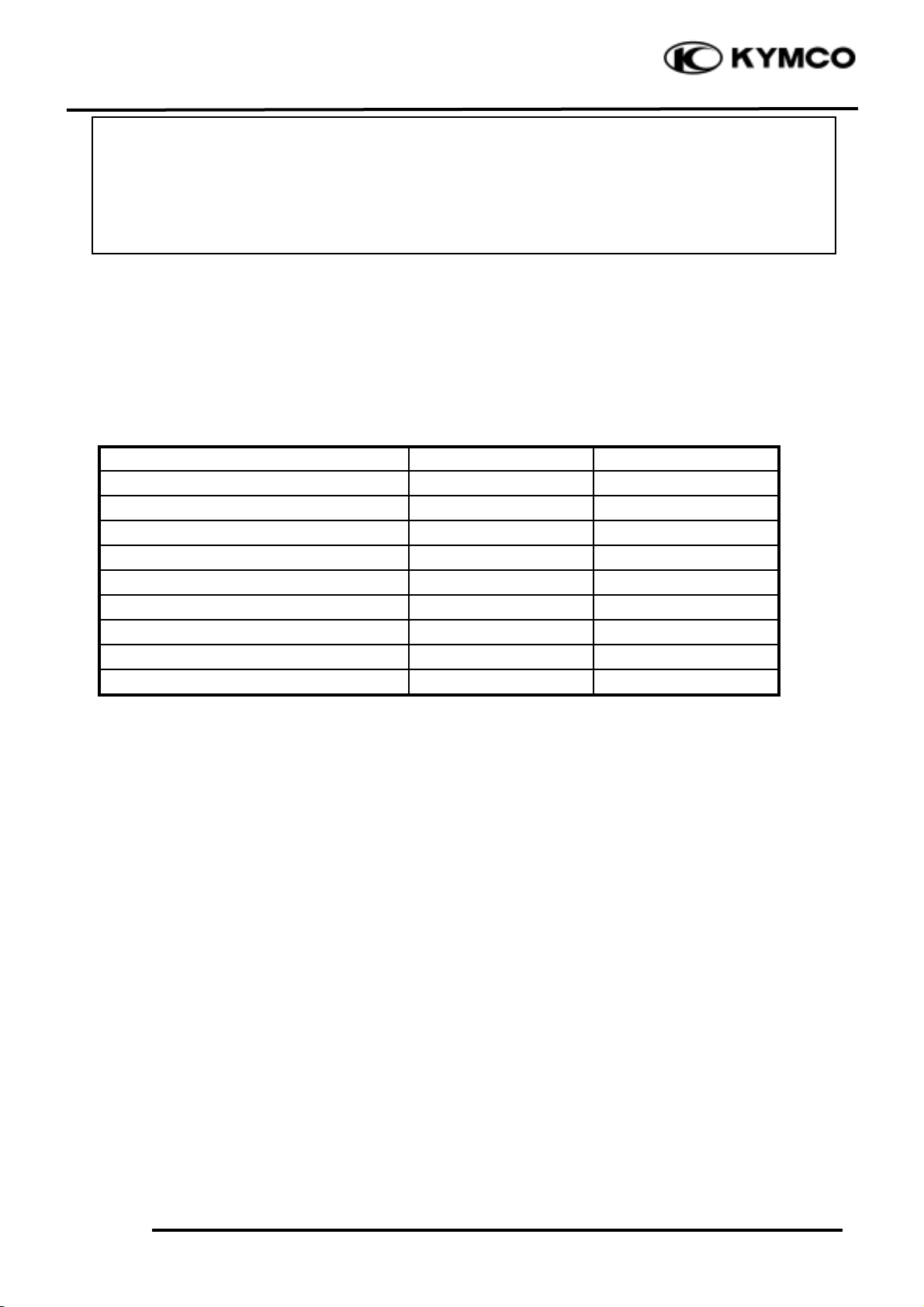
LEFT CRANKCASE COVER
REMOVAL
Loosen the drive belt air tube band screw.
Remove the eight left crankcase cover bolts
and left crankcase cover.
Remove the seal rubber and dowel pins.
Inspect the seal rubber for damage or
deterioration.
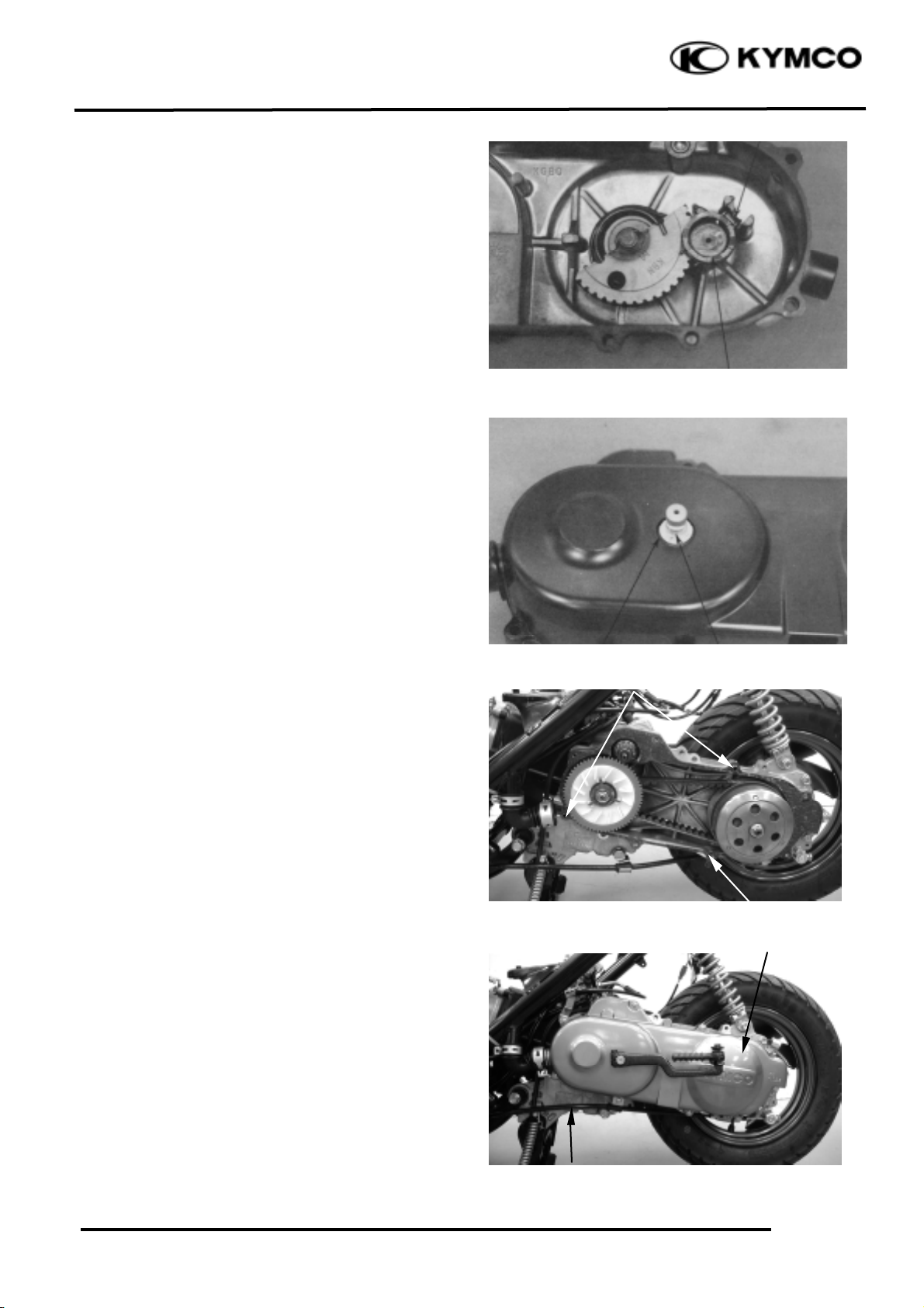
KICK STARTER
REMOVAL
Remove the kick lever from the kick starter
spindle.
Remove the circlip and washer from the kick
starter spindle.
Gently turn the kick starter spindle to remove
the starter driven gear together with the
friction spring.
Remove the kick starter spindle and return
spring from the left crankcase cover.
Remove the kick starter spindle bushings.
Return Spring
Kick Starter Spindle
Friction Spring
Kick Starter Spindle
Circlip
Starter Driven Gear
Washer
Use specified genuine parts for replacement.
*
Air Tube Band
Bolts
Left Crankcase Cover
Page 4
9. DRIVE AND DRIVEN PULLEYS/
KICK STARTER
9-3
FILLY LX 50
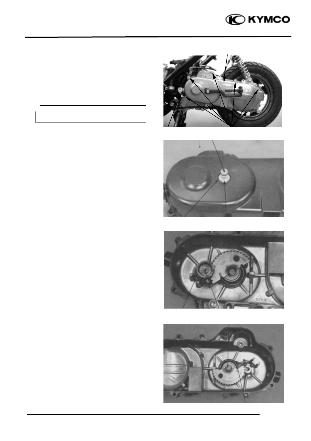
INSPECTION
Inspect the kick starter spindle and gear for
wear or damage.
Inspect the return spring for weakness or
damage.
Inspect the kick starter spindle bushings for
wear or damage.
Inspect the starter driven gear for wear or
damage.
Inspect the friction spring for wear or
damage.
Inspect the kick starter spindle and starter
driven gear forcing parts for wear or damage.
INSTALLATION
Install the kick starter spindle bushings and
return spring onto the left crankcase cover.
Starter Driven Gear Shaft Forcing
Friction Spring
Starter Driven Gear
Spindle
Return Spring
Plastic Bushing
Spindle Bushing
Kick Starter Spindle Forcing Part
Kick Starter Spindle
Return Spring
Page 5
9. DRIVE AND DRIVEN PULLEYS/
KICK STARTER
9-4
FILLY LX 50
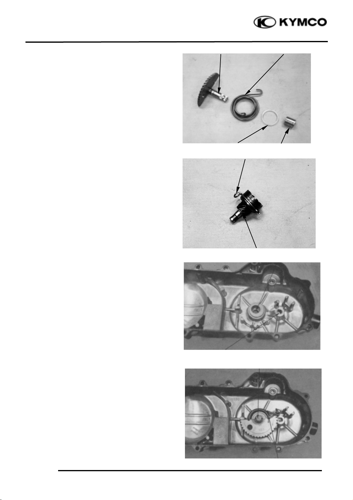
Install the starter driven gear and friction
spring onto the left crankcase cover as the
figure shown.
First install the washer and then install the
circlip.
Install the kick lever.
LEFT CRANKCASE COVER
INSTALLATION
First install the dowel pins.
Install the seal rubber.
Install the left crankcase cover and tighten the
eight left crankcase cover bolts diagonally.
Connect the drive belt air tube and tighten the
tube band screw.
Install the rear brake cable clamp.
Rear Brake Cable Clamp
Washer
Left Crankcase Cover
Starter Driven Gear
Friction Spring
Circlip
Dowel Pins
Seal Rubber
Page 6

9. DRIVE AND DRIVEN PULLEYS/
KICK STARTER
9-5
FILLY LX 50
DRIVE BELT
REMOVAL
Remove the left crankcase cover.
INSPECTION
Check the drive belt for cracks, separation or
abnormal or excessive wear.
Measure the drive belt width.
Service Limit: 16.5mm
REPLACEMENT
Remove the eight left crankcase cover bolts
and left crankcase cover. (!9-2)
Hold the clutch outer with an universal holder
and remove the clutch outer nut.
Universal Holder
Hold the drive pulley using a holder and
remove the drive face nut, starting ratchet and
washer.
Remove the drive pulley face.
Remove the drive belt from the clutch/driven
pulley.
Drive Pulley Face
Universal Holder
Clutch Outer
Nut
Drive Face Nut
Clutch/Driven Pulley
Special
Page 7

9. DRIVE AND DRIVEN PULLEYS/
KICK STARTER
9-6
FILLY LX 50
INSTALLATION
Turn the driven pulley clockwise to widen
the drive belt groove and lay a new drive belt
on the driven pulley.
Set the drive belt on the drive pulley face
collar.
Install the drive pulley face, starting ratchet
washer. Install and tighten the drive face nut.
DRIVE PULLEY
REMOVAL
Hold the drive pulley using a holder and
remove the drive face nut, starting ratchet and
washer.
Remove the drive pulley face.
DISASSEMBLY
Remove the movable drive face assembly and
drive pulley collar from the crankshaft.
Drive Pulley Collar
When installing, align the tooth space of
the drive pulley face and starting ratchet
with the crankshaft tooth and then
tighten the nut.
*
Movable Drive Face Assembly
Starting Ratchet
Drive Belt
Drive Belt
Drive Pulley Face
Drive Face Nut
Starting Ratchet
10mmWasher
Drive Pulley Face
Drive Face Nut (10mm)
Page 8

9. DRIVE AND DRIVEN PULLEYS/
KICK STARTER
9-7
FILLY LX 50
Remove the ramp plate.
Remove the weight rollers.
INSPECTION
Check each weight roller for wear or damage.
Measure each weight roller O.D.
Service Limit: 12.4mm replace if below
Check the drive pulley collar for wear or
damage.
Measure the O.D. of the drive pulley collar
sliding surface.
Service Limit: 19.97mm replace if below
Ramp Plate
Weight Roller
Page 9

9. DRIVE AND DRIVEN PULLEYS/
KICK STARTER
9-8
FILLY LX 50
INSTALLATION
Install the drive pulley collar and movable
drive face onto the crankshaft.
Set the drive belt on the drive pulley collar.
Install the drive pulley face and tighten the
drive face nut. (!9-6)
Torque: 5.5~6.5kgf-m
STARTER PINION
REMOVAL
Remove the left crankcase cover.
Remove the drive pulley.
Remove the starter pinion holder.
Remove the starter pinion.
INSPECTION
Inspect the starter pinion shaft forcing part
for wear or damage.
Inspect the starter pinion for smooth
operation.
Inspect the starter pinion and shaft for wear
or damage.
INSTALLATION
Apply a small amount of grease to the starter
pinion shaft and install it in the reverse order
of removal.
Do not get oil or grease on the drive belt
or pulley faces.
*
Movable Drive Face
Starter Pinion
Drive Pulley Collar
Starter Pinion Shaft
Page 10

9. DRIVE AND DRIVEN PULLEYS/
KICK STARTER
9-9
FILLY LX 50
CLUTCH/DRIVEN PULLEY
REMOVAL
Remove the drive pulley. (!9-6)
Hold the clutch outer with the universal
holder and remove the clutch outer nut.
Remove the clutch outer.
Universal Holder
Remove the clutch/driven pulley assembly
Remove the drive belt from the clutch/driven
pulley assembly.
DISASSEMBLY
Hold the clutch/driven pulley assembly with
the clutch spring compressor.
Set the clutch spring compressor in a vise and
remove the 39mm clutch drive plate nut.
Loosen the clutch spring compressor and
disassemble the driven pulley assembly.
Clutch Spring Compressor
Remove the seal collar.
Clutch Outer
Universal Holder
Seal Collar
Clutch Spring Compressor
Lock Nut Wrench, 39mm
Nut
Clutch/Driven Pulley
Special
Special
Page 11

9. DRIVE AND DRIVEN PULLEYS/
KICK STARTER
9-10
FILLY LX 50
Pull out the guide roller pins and guide rollers.
Remove the movable driven face from the
driven face.
Remove the O-rings and oil seal from the
movable driven face.
INSPECTION
Inspect the clutch outer for wear or damage.
Measure the clutch outer I.D.
Service Limit: 107.5mm replace if over
Check the clutch shoes for wear or damage.
Measure the clutch lining thickness.
Service Limit: 2.0mm replace if below
Measure the driven face spring free length.
Service Limit: 92.8mm replace if below
Guide Roller Pin
Movable Driven Face
O-rings
Oil Seal
Page 12

9. DRIVE AND DRIVEN PULLEYS/
KICK STARTER
9-11
FILLY LX 50
Check the driven face for wear or damage.
Measure the driven face O.D.
Service Limit: 33.94mm replace if below
Check the movable driven face for wear or
damage.
Measure the movable driven face I.D.
Service Limit: 34.06mm replace if over
DRIVEN PULLEY FACE BEARING
REPLACEMENT
Drive the inner needle bearing out of the
driven pulley face.
Discard the removed bearing and replace with
a new one.
Remove the snap ring and drive the outer
bearing out of the driven face.
Apply grease to the outer bearing.
Drive a new outer bearing into the driven face
with the sealed end facing up.
Seat the snap ring in its groove.
Inner Bearing
Outer Bearing
Pack all bearing cavities with
5.0_ 5.6g grease.
Specified grease: Heat resistance 230°C
*
Snap Ring
Bearing Remover
Page 13

9. DRIVE AND DRIVEN PULLEYS/
KICK STARTER
9-12
FILLY LX 50
Press a new needle bearing into the driven
face.
ASS EMBLY
Install the movable driven face onto the
driven face.
Install the O-rings, guide rollers and guide
roller pins.
Install the a new oil seal.
Install the seal collar.
Set the driven pulley assembly, driven face
spring and clutch assembly onto the clutch
spring compressor.
Compress the clutch spring compressor and
install the 39mm drive plate nut.
Set the clutch spring compressor in a vise and
tighten the drive plate nut to the specified
torque.
Torque: 5.0_ 6.0kgf-m
Clutch Spring Compressor
Movable Driven Face
Guide Roller Pin
Outer Driver, 24x26mm
Clutch Spring Compressor
Lock Nut Wrench, 39mm
O-rings
Oil Seal
Seal Collar
Driver Handle
Pilot, 17mm
Special
Page 14

9. DRIVE AND DRIVEN PULLEYS/
KICK STARTER
9-13
FILLY LX 50
INSTALLATION
Lay the drive belt on the driven pulley and
install the clutch/driven pulley onto the drive
shaft.
Install the clutch outer.
Hold the clutch outer with the universal
holder.
Install and tighten the 10mm clutch outer nut.
Torque: 3.5~4.5kgf-m
Install the left crankcase cover. (!9-4)
Clutch Outer
Universal Holder
Clutch/Driven Pulley
Nut
 Loading...