

Page 1
18. EVAPORATIVE/EXHAUST EMISSION
CONTROL SYSTEM
18-0
FILLY LX 50
18
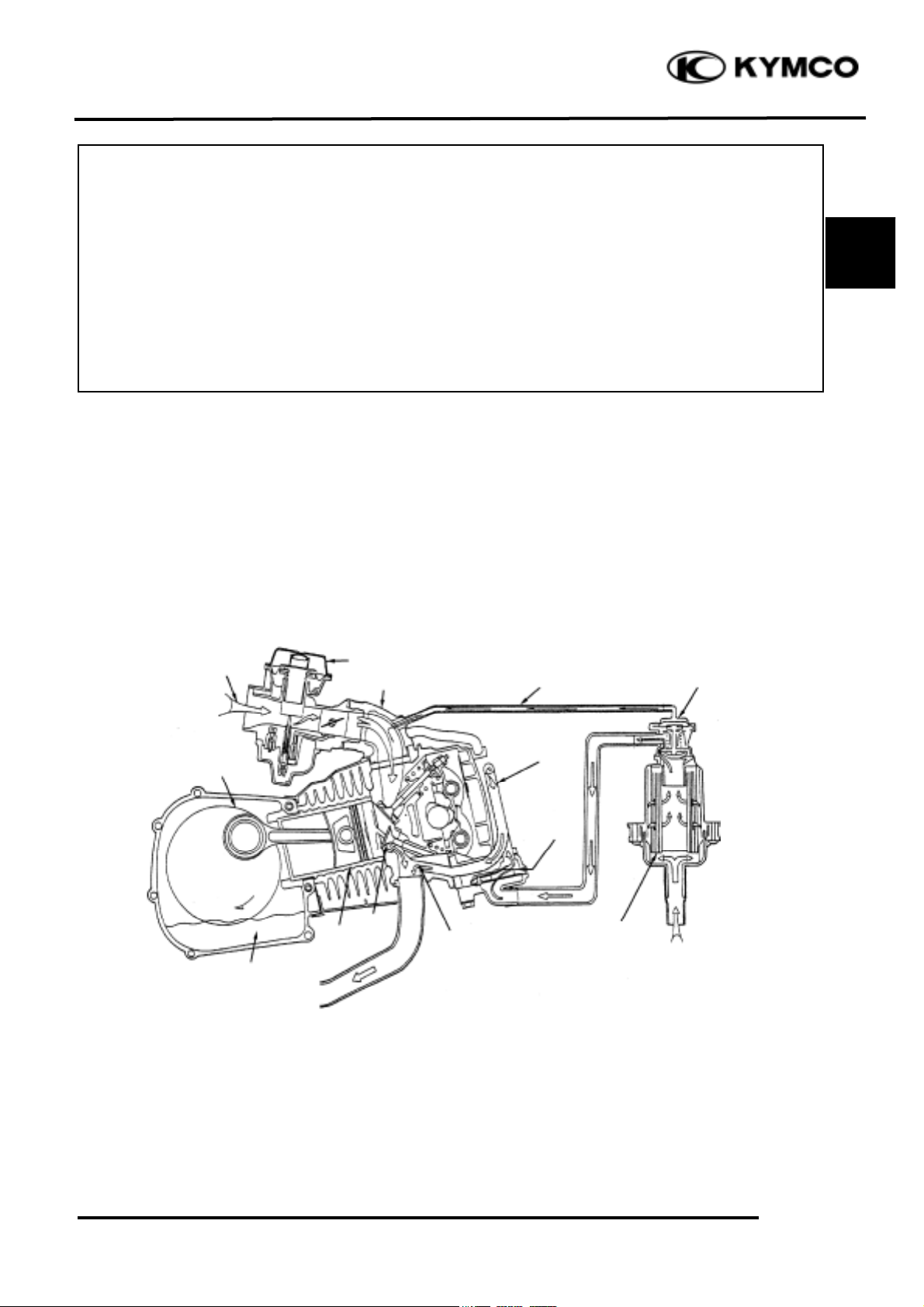
EXHAUST EMISSION CONTROL SYSTEM DIAGRAM
18
EXHAUST EMISSION CONTROL SYSTEM DIAGRAM
.................................................
18-0
EXHAUST EMISSION CONTROL SYSTEM
......................................................................
18-1
SERVICE INFORMATION
....................................................................................................
18-1
TROUBLESHOOTING
...........................................................................................................
18-1
MAINTENANCE SCHEDULE
..............................................................................................
18-2
SECONDARY AIR CLEANER
...............................................................................................
18-3
AIR INJECTION CUT-OFF VALVE (A.I.C.V.)
....................................................................
18-4
REED VALVE
..........................................................................................................................
18-5
EXHAUST MUFFLER
...........................................................................................................
18-6
EXHAUST EMISSION RELATED SYSTEM INSPECTION
...............................................
18-7
Secondary
Air Cleaner
Carburetor
Fresh Air
Fresh Air
Exhaust
Intake Manifold
Piston
Crankshaft
Engine Oil
Valve
Reed Valve
Secondary
Air Inlet
Secondary Air
Vacuum Tube
Air Injection
Cut-off Valve
Page 2

18. EVAPORATIVE/EXHAUST EMISSION
CONTROL SYSTEM
18-1
FILLY LX 50
EXHAUST EMISSION CONTROL SYSTEM
The exhaust emission control system adopted in this model utilizes the reed valve to draw
secondary air into the exhaust system for re-combustion by means of exhaust pulsation so as to
minimize the exhaust emission.
FUNCTION
Item
Purpose
Function
Secondary Air
Cleaner
Filter secondary air.
It filters the fresh air drawn for re-burning to
prevent dirt or dust from affecting the operation of
the air injection cut-off valve.
Air Injection Cutoff Valve
Prevent exhaust
muffler noise and
backfiring at sudden
deceleration.
The air injection cut-off valve usually opens to lead
air into the exhaust muffler in which air is reburned to reduce CO. When the throttle valve
closes suddenly, the air injection cut-off valve is
actuated by vacuum to close and cut off secondary
air in order to prevent exhaust muffler backfiring
due to air in the exhaust system.
Reed Valve
Control the secondary
air inlet to reduce CO.
When the motorcycle speed is less than 50km per
hour, the reed valve operates to draw secondary air
into the exhaust system for re-combustion.
SERVICE INFORMATION
GENERAL INSTRUCTIONS
• During operation, be careful to avoid scalding caused by the exhaust muffler.
• Note the locations of tubes for proper installation.
• Replace any damaged tube with a new one.
• Make sure to tighten the connector of each tube securely
TOOLS SPECIFICATIONS
• Vacuum pump- Air injection cut-off valve actuating pressure-
250mm/Hg- 30 liter/min.
Reed valve stopper clearance- 6.6mm
TROUBLESHOOTING
High CO at idle speed Exhaust muffler noise
• Damaged or clogged reed valve • Faulty air injection cut-off valve
• Damaged or clogged air injection cut-off valve • Broken vacuum tube
• Clogged air cleaner • Faulty reed valve
Backfiring at sudden deceleration
• Damaged reed valve (malfunction)
• Faulty air injection cut-off valve (unable to close)
• Carburetor incorrectly adjusted
• Faulty air cut-off valve
• Leaking vacuum tube
Page 3
18. EVAPORATIVE/EXHAUST EMISSION
CONTROL SYSTEM
18-2
FILLY LX 50
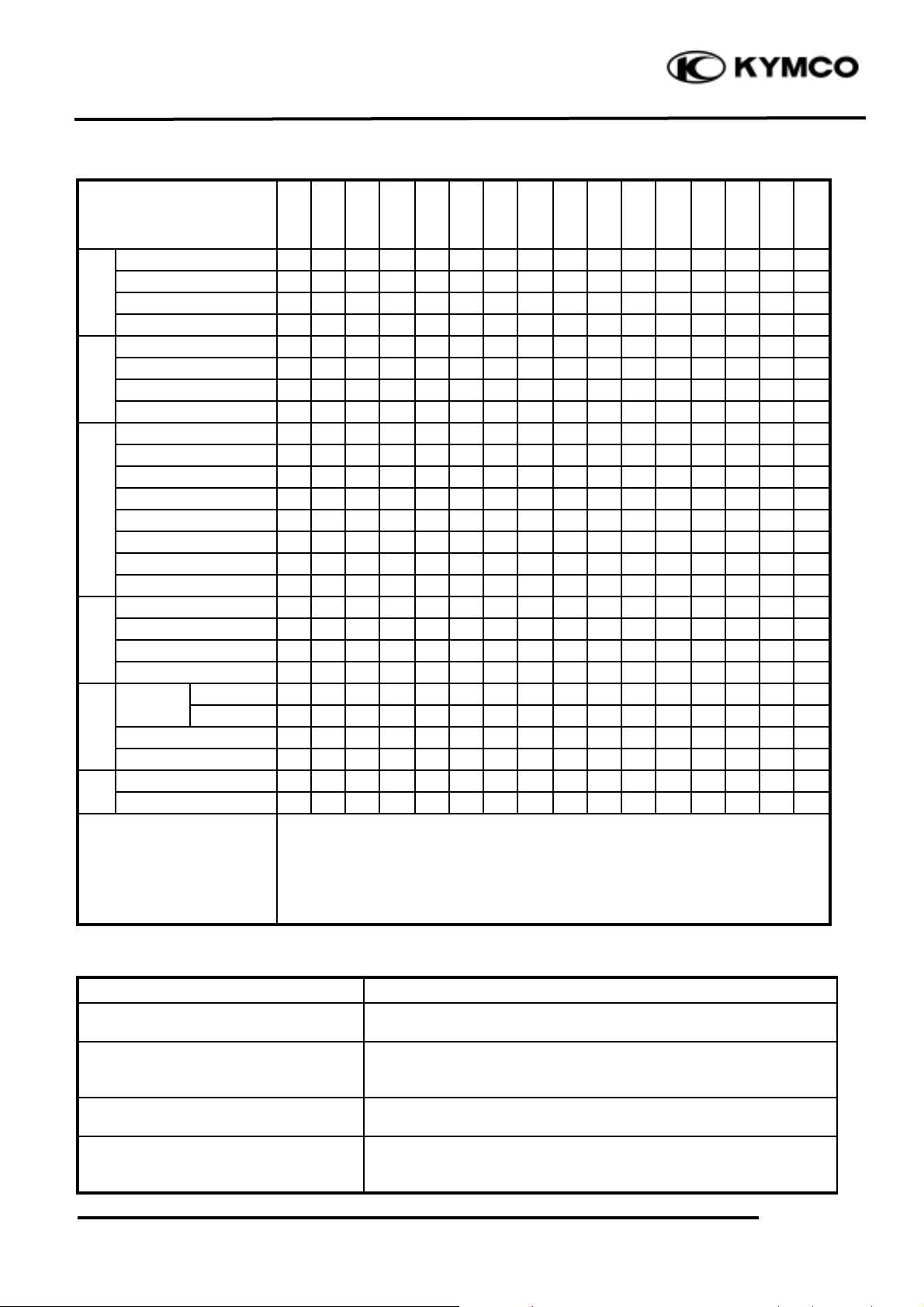
MAINTENANCE SCHEDULE:
(1) PERIODIC MAINTENANCE
Service Mileage
Item
300
1000
2000
3000
4000
5000
6000
7000
8000
9000
100001100012000130001400015000
Engine oil
RRRRRRR
R
Oil filter screen
CCCCC
Gear oil
RRR
R
Lubrication
System
Motor oil filter
III
Fuel filter
III
I
Fuel filter screen
CCC
C
Carburetor
AAA
A
Fuel System
Fuel line
III
Air cleaner
CRR
R
Charcoal canister
III
I
Secondary air cleaner
IRR
R
Secondary air inlet line
I
Intake manifold screw
I
Purge control valve
III
I
Air lines
III
Air Supply System
Catalytic converter
III
I
Cam chain
III
I
Drive chain
III
I
Drive belt
III
I
Drive
System
Valve clearance
III
I
Spark
4-stroke
I
R
Plug
2-stroke
IRR
R
C.D.I.
III
Ignition
System
Ignition system wires
III
Bolts and nuts
TTTTTTTTTTTTTTT
Other
Brake system
AAAAAAAAAAAAAAA
Remarks
I: Inspect, A: Adjust, C: Clean, R: Replace, T: Tighten
•During riding or inspection, if any part is found to be cleaned, adjusted
or replaced, do it directly and take a record if the exhaust emission
control system is not seriously affected. It must be reported and
approved if the exhaust emission control system is seriously affected.
(2) IRREGULAR MAINTENANCE:
Item
Contents
Ignition system
Inspect and repair when obvious symptoms of ignition
failure, engine overheating and stalling are found frequently.
Carbon deposit removal
Remove carbon deposits from the exhaust system, cylinder
head and piston head when the engine horsepower decreases
greatly during the service mileage of 10000_ 15000 km.
Transmission system
Perform CVT system maintenance and inspection when the
engine performance decreases obviously.
Piston
Severe use in the first 1000 km may cause worn or seized
cylinder, piston and piston rings. Clean or replace with new
ones if necessary.
Page 4

18. EVAPORATIVE/EXHAUST EMISSION
CONTROL SYSTEM
18-3
FILLY LX 50
SECONDARY AIR CLEANER
REMOVAL
Remove the frame body covers.
Remove the two nuts attaching the rear light
shell.
Remove the rear turn signal light bulb and
replace with a new one.
Disconnect the secondary air cleaner
connecting tube.
Remove the air cleaner attaching bolts and the
air cleaner.
DISASSEMBLY
Remove the two screws attaching the air
cleaner cover to remove the cover.
Remove the air cleaner element.
Inspect the air cleaner.
INSTALLATION
The installation sequence is the reverse of
removal.
Nuts
Rear Light Shell
Air Outlet Tube
Air Cleaner Element
Screws
Air Inlet Tube
Vacuum Tube
Air Injection Cut-off Valve
Tube to Reed Valve
Secondary Air
Cleaner
Bolt
Air Injection
Cut-off Valve
• The secondary air cleaner must be
assembled and installed properly to
avoid dust entering the air cleaner.
*
Page 5

18. EVAPORATIVE/EXHAUST EMISSION
CONTROL SYSTEM
18-4
FILLY LX 50
AIR INJECTION CUT-OFF VALVE
INSPECTION
Inspect the air injection cut-off valve flow
using a vacuum pump. If the flow is not
within the specified values, replace with a
new one.
The flow should be at least 30 liter/min when
a vacuum of 250mm/Hg is applied. The flow
should be at least 1.6 liter/min when a vacuum
of 320mm/Hg is applied. Check each
connecting tube for cracks or damage and
replace if necessary.
INSTALLATION
The installation sequence is the reverse of
removal.
Vacuum Pump
Air Injection Cut-off Valve
• When installing, be careful not to bend
or twist the tubes and check for
proper installation.
• The tube length is very important to
its performance, use the tube of same
specification for replacement.
*
Page 6

18. EVAPORATIVE/EXHAUST EMISSION
CONTROL SYSTEM
18-5
FILLY LX 50
REED VALVE
REMOVAL
Remove the met-in box and frame center
cover.
Disconnect the secondary air inlet tube
connector.
Remove the four cylinder head cover bolts
and two secondary air outlet tube bolts.
INSPECTION
Remove the three screws attaching the reed
valve cover and the reed valve.
Check the reed valve for damaged or weak
reeds.
Check the reed valve seat for cracks, damage
or clearance between the seat and reed.
Check the gasket and O-ring for damage or
deterioration and replace if necessary.
Reed valve stopper clearance: 6.6mm
INSTALLATION
Install the reed valve in the reverse order of
removal.
• When installing, be careful not to bend
or twist the tubes and check for
proper installation.
*
Cylinder Head Cover
Bolts
Secondary Air Inlet
Tube Bolt
Reed Stopper
Reed Valve Cover Bolts
Screws
Page 7

18. EVAPORATIVE/EXHAUST EMISSION
CONTROL SYSTEM
18-6
FILLY LX 50
EXHAUST MUFFLER
REMOVAL
Remove the two exhaust muffler joint lock
nuts and two exhaust muffler lock bolts.
Remove the exhaust muffler.
INSPECTION
1. Inspect the exhaust muffler and joint for
damage or crack. Replace if necessary.
2. Inspect the exhaust muffler joint packing
collar for deformation or damage. Replace if
necessary.
INSTALLATION
1. Install the exhaust muffler in the reverse
order of removal.
• The temperature of exhaust muffler is
very high. Be careful to avoid burns
during working.
*
Exhaust Muffler
Lock Bolts
Exhaust Muffler Joint Lock Nut
• A large amount of unburned mixture
flowing into the high-heat catalytic
converter will burn again and cause damage
to the converter due to overheat. Pay
attention to the following.
• Use 92# or 95# nonleaded gasoline only.
(Leaded gasoline will cause catalytic
converter failure.)
• During riding, do not turn the ignition
switch OFF to avoid a large amount of
unburned mixture flowing into the exhaust
muffler.
• Faulty ignition system or fuel system will
cause overheat and damage to the catalytic
converter.
*
Page 8

18. EVAPORATIVE/EXHAUST EMISSION
CONTROL SYSTEM
18-7
FILLY LX 50
EXHAUST EMISSION RELATED
SYSTEM INSPECTION
Clean or replace the air cleaner. (!3-4)
Clean and adjust the carburetor. (!3-5)
Inspect the auto bystarter system. (!5-4)
Clean and inspect the spark plug. (!3-4)
Inspect the ignition system. (!3-6)
EXHAUST EMISSION TEST AND
ADJUSTMENT
1. Start the engine and warm up for several
minutes. (Engine surface temperature
50℃_ 60℃ )
2. Adjust the idle speed to 1900rpm.
3. Connect the emission tester sampling pipe
to the exhaust muffler.
Standard:
CO: 2.5±0.5%
HC: 700PPM max.
4. If CO or HC exceeds the specified values,
adjust the carburetor pilot screw (P.S.)
until CO and HC are within the specified
standard values.
P.S. Opening: 2±_ turns
5. If the adjustment of carburetor makes no
difference, inspect exhaust emission related
system. (!18-9)
 Loading...