

Page 1

2. EXHAUST MUFFLER/FRAME COVERS
2-0
2
__________________________________________________________________________________
__________________________________________________________________________________
__________________________________________________________________________________
__________________________________________________________________________________
__________________________________________________________________________________
EXHAUST MUFFLER/FRAME COVERS
__________________________________________________________________________________
SCHEMATIC DRAWING ---------------------------------------------- 2-1
SERVICE INFORMATION -------------------------------------------- 2-2
TROUBLESHOOTING ------------------------------------------------- 2-2
FRAME COVERS REMOVAL----------------------------------------- 2-3
EXHAUST MUFFLER REMOVAL ----------------------------------- 2-6
2
Page 2
2. EXHAUST MUFFLER/FRAME COVERS
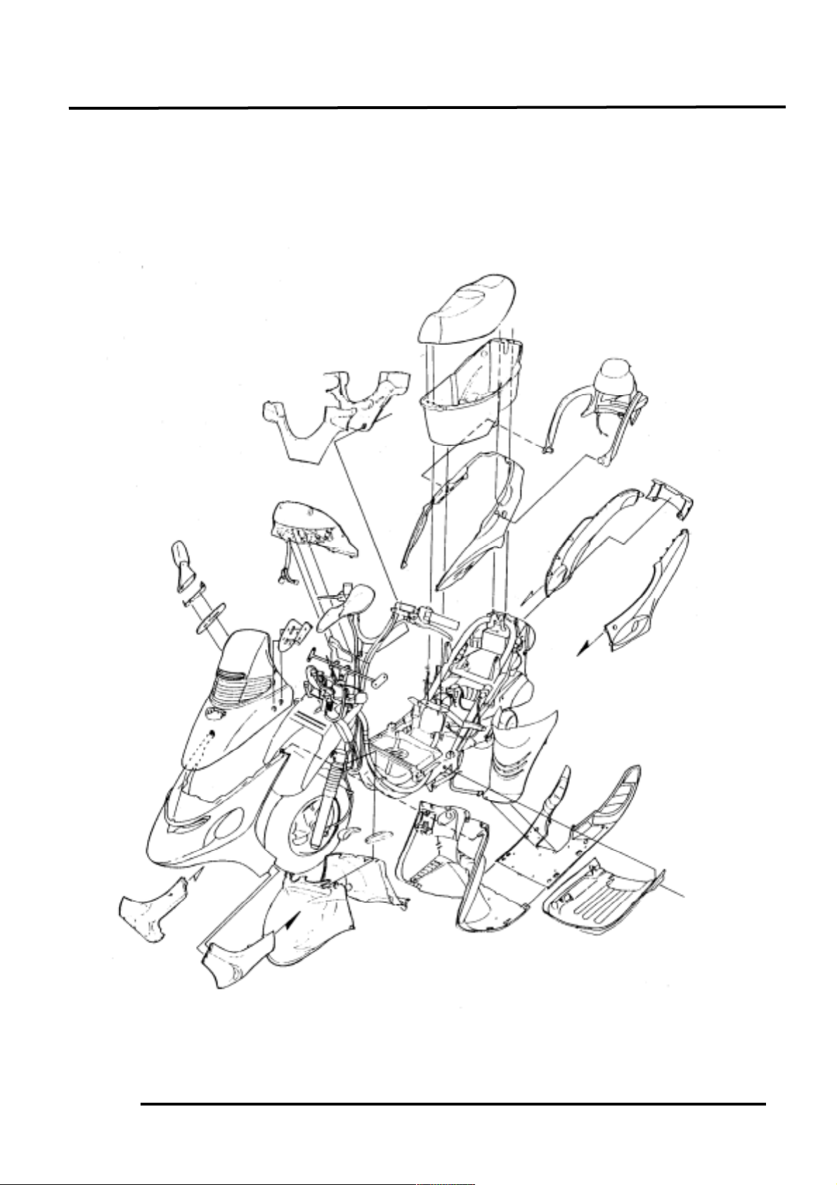
2-1
SCHEMATIC DRAWING
Page 3

2. EXHAUST MUFFLER/FRAME COVERS
2-2
SERVICE INFORMATION
GENERAL INSTRUCTIONS
• When removing frame covers, use care not to pull them by force because the cover joint claws
may be damaged.
• Make sure to route cables and harnesses according to the Cable & Harness Routing.
TORQUE VALUES
Exhaust muffler lock bolt 3.5kg-m
Exhaust muffler joint lock nut 1.2kg-m
TROUBLESHOOTING
Noisy exhaust muffler
• Damaged exhaust muffler
• Exhaust muffler joint air leaks
Lack of power
• Caved exhaust muffler
• Clogged exhaust muffler
• Exhaust muffler air leaks
Page 4

2. EXHAUST MUFFLER/FRAME COVERS
2-3
FRAME COVERS REMOVAL
REAR CARRIER & HAND RAIL
REMOVAL
Remove the met-in box:
First remove the two bolts and two nuts
attaching the met-in box.
Remove the bolt attaching the center cover.
Remove the met-in box.
Remove the hand rail right and left lock bolts.
Remove the two hex bolts and one stay bolt
attaching the rear carrier.
Disconnect the two stoplight wire connector
on the rear carrier.
Remove the rear carrier and hand rail.
FRAME BODY COVER REMOVAL
Remove the two screws on the bottom of the
center cover.
Remove the center cover.
Remove the two screws attaching the front
part of the frame body cover.
Remove the two screws attaching the rear
protective cover.
Remove the rear protective cover.
Remove the two screws attaching the rear
ends of the right and left side rails.
Center Cover Bolt
Screws
Screws
Bolts/Nuts
Hex Bolts
Lock Bolts
Frame Body Cover
Center Cover
Rear Protective
Screws
Screws
Page 5

2. EXHAUST MUFFLER/FRAME COVERS
2-4
Remove the screws attaching the right and left
side covers.
Remove the right and left side covers by
pulling them backward.
Remove the right and left screws on the rear
part of the frame body cover.
Disconnect the seat lock wire.
Remove the frame body cover.
FLOOR BOARD REMOVAL
Remove the floor mat.
Remove the center cover. (2-3)
Remove the ten screws and two bolts
attaching the front right and left side covers.
Remove the two bottom cover adjusting
screws.
Remove the front right and left side covers.
Remove the six bolts attaching the floor
board.
Remove the floor board .
The installation sequence is the reverse of
removal.
Screws
Side Cover
Seat Lock Wire
Screw
Screws
Adjusting Screws
Bolts
Floor Board
Bolts
Screw
Page 6

2. EXHAUST MUFFLER/FRAME COVERS
2-5
FRONT UPPER COVER REMOVAL
Remove the right and left rearview mirrors.
Remove the two screws on the back of the
front upper cover.
Remove the two bolts on the front of the
front upper cover.
Disconnect the headlight wire connector.
Remove the front upper cover.
The installation sequence is the reverse of
removal.
FRONT LOWER COVER REMOVAL
First remove the front upper cover.
Remove the two screws attaching the front
lower cover.
Remove the four screws on the back of the
front lower cover.
Disconnect the right/left turn signal light wire
connectors.
Remove the front lower cover
The installation sequence is the reverse of
removal.
LEG SHIELD REMOVAL
Remove the front upper cover.
Remove the front lower cover.
Remove the four screws attaching the leg
shield and instruments and remove the fuse
box.
Remove the nut attaching the leg shield.
Remove the adjusting screw which combines
the leg shield with instruments.
Remove the leg shield.
The installation sequence is the reverse of
removal.
Screws
Screws
Screws
Adjusting Screw
Screws
Bolts
Page 7

2. EXHAUST MUFFLER/FRAME COVERS
2-6
HANDLEBAR COVER REMOVAL
Remove the two screws and one bolt
attaching the handlebar rear cover.
First remove the four screws attaching the
handlebar front cover.
Remove the handlebar front cover.
Remove the handlebar rear cover.
The installation sequence is the reverse of
removal.
BOTTOM COVER REMOVAL
Remove the side stand.
Remove the four bolts attaching the bottom
cover.
Remove the bottom cover.
FRONT INNER FENDER A/B REMOVAL
Remove the front upper cover. (2-5)
Remove the front lower cover. (2-5)
Remove the screws which combines inner
fender A with inner fender B.
Remove the two bolts attaching the inner
fender A.
Separate inner fenders A and B.
The installation sequence is the reverse of
removal.
EXHAUST MUFFLER REMOVAL
Remove the two exhaust muffler joint lock
nuts.
Remove the two exhaust muffler lock bolts to
remove the exhaust muffler.
Remove the exhaust muffler joint packing
collar.
The installation sequence is the reverse of
removal.
Torque:
Exhaust muffler joint lock nut: 1.2kg-m
Exhaust muffler lock bolt: 3.5kg-m
Screws
Screws
fender
Screws
Bolt
Lock Bolts
Bolts
Bolt
Bolts
Side Stand
Bottom Cover
Joint Lock Nut
 Loading...