

Page 1

19. SWITCHES/HORN/FUEL UNIT/THERMOSTATIC SWITCH
/TEMPERATURE GAUGE/INSTRUMENTS/LIGHTS
19-0
19
__________________________________________________________________________________
__________________________________________________________________________________
__________________________________________________________________________________
__________________________________________________________________________________
__________________________________________________________________________________
SWITCHES/HORN/FUEL UNIT/THERMOSTATIC
SWITCH/TEMPERATURE GAUGE/ INSTRUMENTS/LIGHTS
__________________________________________________________________________________
ELECTRICAL EQUIPMENT LAYOUT------------------------------ 19-1
SERVICE INFORMATION -------------------------------------------- 19-2
TROUBLESHOOTING ------------------------------------------------- 19-2
SWITCHES -------------------------------------------------------------- 19-3
HORN INSPECTION --------------------------------------------------- 19-5
FUEL UNIT-------------------------------------------------------------- 19-5
THERMOSTATIC SWITCH ------------------------------------------- 19-6
TEMPERATURE GAUGE --------------------------------------------- 19-6
INSTRUMENTS--------------------------------------------------------- 19-7
LIGHTS ------------------------------------------------------------------ 19-8
19
Page 2
19. SWITCHES/HORN/FUEL UNIT/THERMOSTATIC SWITCH
/TEMPERATURE GAUGE/INSTRUMENTS/LIGHTS
19-1
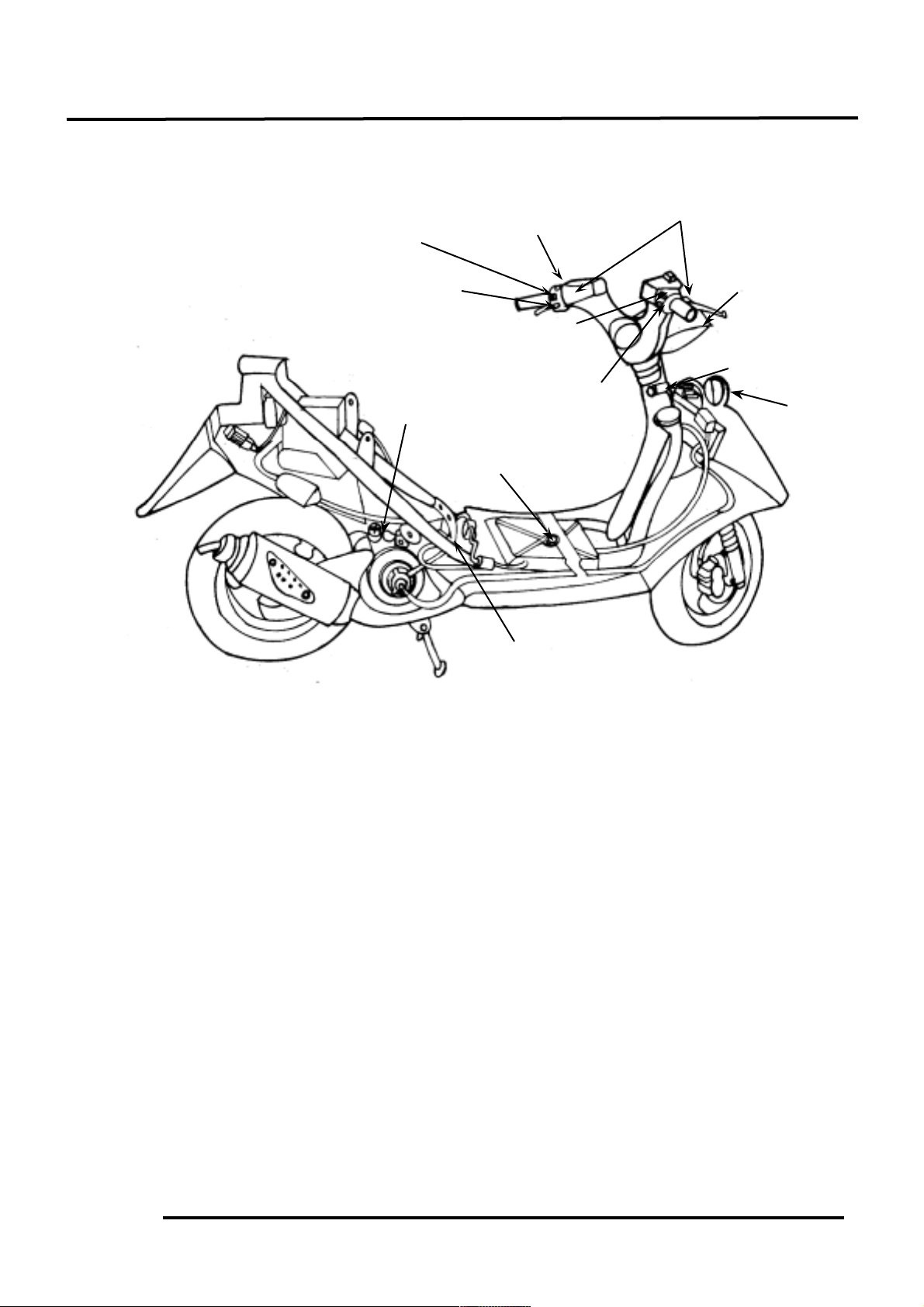
ELECTRICAL EQUIPMENT LAYOUT
Fuel Unit
Starter Button
Horn
Ignition Switch
Auto Bystarter
Thermosensor
Turn Signal Switch
Stop Switches
Horn Button
Headlight
Dimmer Switch
Instruments
Headlight
Switch
Page 3

19. SWITCHES/HORN/FUEL UNIT/THERMOSTATIC SWITCH
/TEMPERATURE GAUGE/INSTRUMENTS/LIGHTS
19-2
SERVICE INFORMATION
GENERAL INSTRUCTIONS
• After installation of each switch, a continuity check must be performed. A continuity check can
usually be made without removing the part from the motorcycle.
TESTING INSTRUMENT
Electric tester
SPECIAL TOOL
Fuel unit wrench
TROUBLESHOOTING
Lights do not come on when ignition Temperature gauge does not register
switch is “ON” correctly
• Burned bulb • Faulty temperature gauge
• Faulty switch • Faulty thermosensor
• Poorly connected, broken or shorted wire • Broken or shorted wire between
temperature gauge and thermosensor
Fuel gauge pointer does not move or
register correctly
• Faulty fuel gauge
• Faulty fuel unit
• Poorly connected wire between fuel
gauge and fuel unit
• Fuse burned out
SPECIFICATIONS
Fuse 20A
Headlight bulb 12V 35W/35W
Turn signal light bulb 12V 10W
Stoplight/taillight 12V 5W
License plate light 12V 3.4W
Instrument light 12V 1.7W
Position light 12V 3W/5W
Turn signal indicator light 12V 10W
Page 4

19. SWITCHES/HORN/FUEL UNIT/THERMOSTATIC SWITCH
/TEMPERATURE GAUGE/INSTRUMENTS/LIGHTS
19-3
SWITCHES
IGNITION SWITCH INSPECTION
Remove the frame front covers. (2-5)
Disconnect the ignition switch wire couplers.
Check for continuity between the wire
terminals.
Color
Position
R
B/WGB
LOCK
○
○
OFF
○
○
ON○○
HEADLIGHT SWITCH INSPECTION
Remove the frame front covers. (2-5)
Disconnect the headlight switch wire
couplers. Check for continuity between the
wire terminals.
Color
Position
Y
BR/W
BR
L/W
P
○
○
P
○○○
H
○○○
STARTER SWITCH INSPECTION
Remove the frame front covers. (2-5)
Disconnect the starter switch wire couplers.
Depress the starter button and check for
continuity between the wire terminals.
Color
Position
Y/R
G
FREE
PUSH
○
○
PASSING SWITCH
Remove the front upper cover. (2-5)
Disconnect the headlight switch wire
couplers. Check for continuity between the
passing switch wire terminals.
Color
Position
L
L/W
FREE
PUSH
○
○
Passing Switch
Ignition Switch
Headlight Switch
G
B
B/W
G
R
BR
Y
L/W
P
G
Y/R
L
L/W
Starter Switch
Passing
Page 5

19. SWITCHES/HORN/FUEL UNIT/THERMOSTATIC SWITCH
/TEMPERATURE GAUGE/INSTRUMENTS/LIGHTS
19-4
HORN BUTTON INSPECTION
Remove the frame front covers. (2-5)
Disconnect the horn wire couplers.
Depress the horn button and check for
continuity between the wire terminals.
Color
Position
LG
BR/L
FREE
PUSH
○
○
TURN SIGNAL SWITCH INSPECTION
Remove the frame front covers. (2-5)
Disconnect the turn signal switch wire
couplers and turn on the turn signal switch.
Check for continuity between the wire
terminals.
Color
Position
SBOGR
L
○
○
N
R
○
○
DIMMER SWITCH INSPECTION
Remove the frame front covers. (2-5)
Disconnect the headlight dimmer switch wire
couplers.
Turn on the dimmer switch and check for
continuity between the wire terminals.
Color
Position
L/W
L
W
LO
○
○
N○○
○
HI
○
○
STOP SWITCH INSPECTION
Remove the frame front covers. (2-5)
Disconnect the front/rear stop switch wire
couplers.
Check for continuity between the wire
terminals when the front brake lever is
applied.
Color
Position
BR/L
G/Y
FREE
APPLY
○
○
Horn Button
Turn Signal Switch
Dimmer Switch
Stop Switch
BR/L
G/Y
W
L/W
L
SBOGR
LG
BR/L
Page 6

19. SWITCHES/HORN/FUEL UNIT/THERMOSTATIC SWITCH
/TEMPERATURE GAUGE/INSTRUMENTS/LIGHTS
19-5
HORN INSPECTION
Remove the front upper cover. (2-5)
Disconnect the horn wire couplers.
The horn is normal if it sounds when a 12V
battery is connected across the horn wire
terminals.
FUEL UNIT
FUEL UNIT INSPECTION
Remove the fuel unit.
Disconnect the fuel unit wire connectors.
Measure the resistance between the fuel unit
wire terminals with the float at upper and
lower positions.
Wire Terminals
Upper
Lower
Y/W_ G
33_ 45Ω
500_ 850Ω
L/W_ G
400_ 700Ω
100_ 200Ω
Y/W_ L/W
450_ 750Ω
450_ 750Ω
FUEL GAUGE INSPECTION
Connect the fuel unit wire connectors and
turn the ignition switch “ON”.
Check the fuel gauge needle for correct
indication by moving the fuel unit float up
and down.
Float Position
Needle Position
Upper
“F” (Full)
Lower
“E” (Empty)
Wire Terminals
Needle Position
Y/W_ G
From E to F
L/W_ G
From F to E
The fuel gauge is normal if it operates as
above indicated. If not, check for loosely
tightened nuts, poorly connected terminals or
shorted wires.
Fuel Unit
Before performing the following test,
operate the turn signals to determine that
the battery circuit is normal.
*
Horn
12V Battery
Lower
Upper
Lower
Upper
Upper
Fuel Gauge
Lower
Needle moves
from F to E.
Page 7

19. SWITCHES/HORN/FUEL UNIT/THERMOSTATIC SWITCH
/TEMPERATURE GAUGE/INSTRUMENTS/LIGHTS
19-6
OIL METER
INSPECTION
Remove the met-in box. (2-4)
Remove the frame body cover. (2-4)
Disconnect the oil meter wire connectors
and remove the oil meter. Keep the oil
meter float at the lower position.
Measure the resistances between the wire
terminals as and shown in the left
figure.
Wire Terminals
Resistance
Green/Red(+)_ Black(-)
5_ 16Ω
Green(-)_ Black(+)
∞
Oil Meter Operation Inspection
Connect the oil meter wire connectors and
turn the ignition switch ON.
Measure the resistance between the wire
terminals with the float at upper position.
Green/Red(+)_ Black(-)
About 340Ω
TEMPERATURE GAUGE
Disconnect the wire from the thermosensor
and ground it to the engine.
Turn the ignition switch ON.
The temperature gauge needle should move
all the way to “H”.
Do not leave the thermosensor wire
grounded for longer than 5 seconds or
the temperature gauge will be damaged.
*
Before performing the following test,
operate the turn signals to determine
that the battery circuit is normal.
*
Before removing the oil meter, be sure to
drain the motor oil and do not allow
sparks or flames near the working area.
*
Light OFF
Light ON
Oil Meter
Float
G/RBB
G
G
Page 8

19. SWITCHES/HORN/FUEL UNIT/THERMOSTATIC SWITCH
/TEMPERATURE GAUGE/INSTRUMENTS/LIGHTS
19-7
INSTRUMENTS
REMOVAL
Remove the front upper cover. (2-5)
Disconnect the instrument wire couplers and
connectors.
Disconnect the speedometer cable.
Remove the four instrument cover and leg
shield screws.
Remove the two instrument holder bolts.
Remove the instruments.
DISASSEMBLY/ASSEMBLY
Remove the three instrument holder nuts.
Remove the holder.
Remove the four screws to disassemble the
instruments and instrument cover .
Assemble the instruments in the reverse order
of disassembly.
INSTALLATION
The installation sequence is the reverse of
removal.
Wire Couplers
Speedometer Cable
Screws
Holder Bolts
Screws
Screws
Page 9

19. SWITCHES/HORN/FUEL UNIT/THERMOSTATIC SWITCH
/TEMPERATURE GAUGE/INSTRUMENTS/LIGHTS
19-8
LIGHTS
HEADLIGHT BULB REPLACEMENT
Remove the front upper cover. (2-5)
Disconnect the headlight and turn signal light
wire couplers.
Remove the rubber boot from the bulb socket.
Remove the bulb socket and replace the bulb.
Install the bulb socket, aligning the bulb
socket tab with the groove.
Install the rubber boot.
Install the front cover in the reverse order of
removal.
FRONT POSITION LIGHT BULB
REPLACEMENT
Remove the front upper cover. (2-5)
Disconnect the headlight and turn signal light
wire couplers.
Remove the bulb sockets by turning them
counterclockwise.
Remove the bulbs and replace them with new
ones.
FRONT TURN SIGNAL LIGHT BULB
REPLACEMENT
Remove the two screws attaching the turn
signal light shell and remove the light shell.
Remove the bulb and replace with a new one.
TAILLIGHT/REAR TURN SIGNAL LIGHT
BULB REPLACEMENT
Remove the rear protective cover. (2-3)
Remove the two screws attaching the rear
light shell and remove the light shell.
Remove the bulbs and replace with new ones.
The installation sequence is the reverse of
removal.
Screws
Front Position Light Bulb Sockets
Wire
Bulb Socket
Screws
Wire
 Loading...