

Page 1

16. BATTERY/CHARGING SYSTEM
16-0
16
__________________________________________________________________________________
__________________________________________________________________________________
__________________________________________________________________________________
__________________________________________________________________________________
__________________________________________________________________________________
BATTERY/CHARGING SYSTEM
__________________________________________________________________________________
CHARGING SYSTEM LAYOUT-------------------------------------- 16-1
SERVICE INFORMATION -------------------------------------------- 16-2
TROUBLESHOOTING ------------------------------------------------- 16-3
BATTERY---------------------------------------------------------------- 16-4
CHARGING SYSTEM -------------------------------------------------- 16-5
A.C. GENERATOR INSPECTION ------------------------------------ 16-5
REGULATOR/RECTIFIER INSPECTION --------------------------- 16-6
16
Page 2
16. BATTERY/CHARGING SYSTEM
16-1
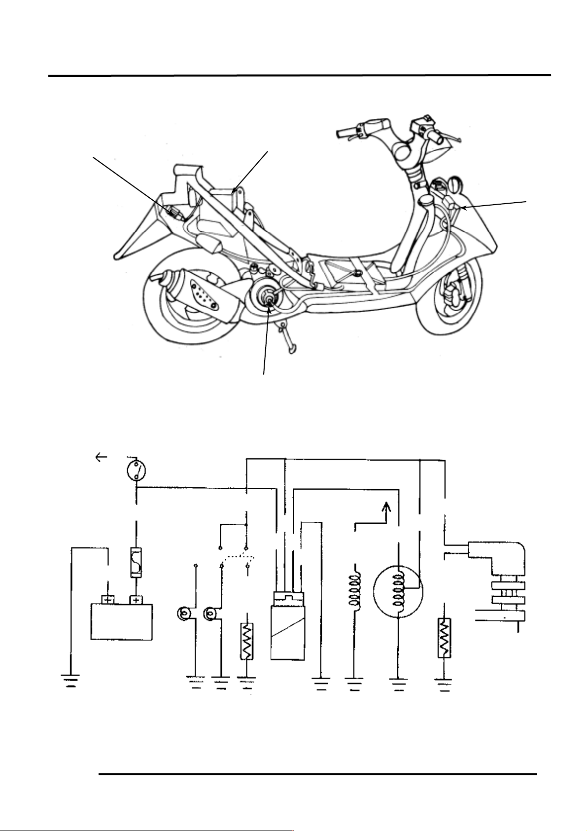
CHARGING SYSTEM LAYOUT
CHARGING CIRCUIT
Fuse
Regulator/Rectifier
A.C. Generator
Battery
Battery
Y
W
5. 9Ω
30W
Wire Harness R
GRWGR
YYY
Auto
Bystarter
Fuse
Regulator/
Rectifier
Ignition Switch
P
Resistor
Resistor
A.C. Generator
Pulser Coil
10.2Ω
5W
L/Y
G/B
Page 3
16. BATTERY/CHARGING SYSTEM
16-2
SERVICE INFORMATION
GENERAL INSTRUCTIONS
• The battery can be charged and discharged repeatedly. If a discharged battery is not used for a
long time, its service life will be shortened. Generally, the capacity of a battery will decrease after
it is used for 2_ 3 years. A capacity-decreased battery will resume its voltage after it is
recharged but its voltage decreases suddenly and then increases when a load is added.
• When a battery is overcharged, some symptoms can be found. If there is a short circuit inside the
battery, no voltage is produced on the battery terminals. If the rectifier won‘t operate, the
voltage will become too high and shorten the battery service life.
• If a battery is not used for a long time, it will discharge by itself and should be recharged every 3
months.
• A new battery filled with electrolyte will generate voltage within a certain time and it should be
recharged when the capacity is insufficient. Recharging a new battery will prolong its service life.
• Inspect the charging system according to the sequence specified in the Troubleshooting.
• Do not disconnect and soon reconnect the power of any electrical equipment because the electronic
parts in the regulator/rectifier will be damaged. Turn off the ignition switch before operation.
• It is not necessary to check the MF battery electrolyte or fill with distilled water.
• Check the load of the whole charging system.
• Do not quick charge the battery. Quick charging should only be done in an emergency.
• Remove the battery from the motorcycle for charging.
• When replacing the battery, do not use a traditional battery.
• When charging, check the voltage with an electric tester.
SPECIFICATIONS
Item
Standard
Capacity
12V4AH
Voltage
Fully charged
13.2V
Battery
(20℃ )
Undercharged
12.3V
Charging current
STD: 0.5A Quick: 5.0A
Charging time
STD: 5-10hr Quick: 30min
Capacity
160W/500rpm
A.C. Generator
Charging coil resistance (20℃ )
Yellow_ Yellow
0.6_ 1.6Ω
Charging rpm
1300rpm max (14V)
Charging performance
1.3A min/2500rpm 2.0A min/6000rpm
Regulator/Rectifier
Limit voltage
14.5±0.5V
TESTING INSTRUMENTS TORQUE VALUES
Ammeter Pulser coil bolt 0.5kg-m
Electric tester Coil lock bolt 0.9kg-m
Tachometer Flywheel nut 3.5_ 4.5kg-m
The battery electrolyte (sulfuric acid) is poisonous and may seriously damage the skin and
eyes. Avoid contact with skin, eyes, or clothing. In case of contact, flush with water and get
prompt medical attention
Page 4

16. BATTERY/CHARGING SYSTEM
16-3
SPECIAL TOOLS
Universal holder
Flywheel puller
TROUBLESHOOTING
No power Intermittent power
• Dead battery • Loose battery cable connection
• Disconnected battery cable • Loose charging system connection
• Fuse burned out • Loose connection or short circuit in
• Faulty ignition switch
ignition system
Low power Charging system failure
• Weak battery • Loose, broken or shorted wire or connector
• Loose battery connection • Faulty regulator/rectifier
• Charging system failure • Faulty A.C. generator
• Faulty regulator/rectifier
Page 5

16. BATTERY/CHARGING SYSTEM
16-4
BATTERY
Remove the seat and met-in box. (2-3)
Remove the battery.
First disconnect the battery negative (-) cable
and then the positive (+) cable.
The installation sequence is the reverse of
removal.
BATTERY VOLTAGE INSPECTION (OPEN
CIRCUIT VOLTAGE)
Disconnect the battery cables.
Measure the voltage between the battery
terminals.
Fully charged : 13.2V
Undercharged : 12.3V max.
CHARGING
Connect the charger positive (+) cable to the
battery positive (+) terminal.
Connect the charger negative (-) cable to the
battery negative (-) terminal.
Charging current : Standard : 0.5A
Quick : 5A
Charging time : Standard : 5_ 10 hours
Quick : 30 minutes
After charging: Open circuit voltage: 12.8V min.
• Quick charging should only be done in
an emergency.
• Measure the voltage 30 minutes after
the battery is charged.
*
Battery charging inspection must be
performed with a voltmeter.
*
When disconnecting the battery positive
(+) cable, do not touch the frame with
tool; otherwise it will cause short circuit
and sparks to fire the fuel.
First connect the positive (+) cable and then
negative (-) cable to avoid short circuit.
• Keep flames and sparks away
from a charging battery.
• Turn power ON/OFF at the
charger, not at the battery terminals to
prevent sparks near the battery.
• Charge the battery according to
the current specified on the battery.
• During quick charging, the
battery temperature should not exceed
Page 6

16. BATTERY/CHARGING SYSTEM
16-5
CHARGING SYSTEM
CURRENT TEST
Warm up the engine before taking readings.
Connect an electric tester across the battery
terminals.
Disconnect the red wire from the fuse
terminal and connect an ammeter between the
red wire lead and the fuse terminal.
Attach a tachometer to the engine.
Start the engine and gradually increase the
engine speed to measure the limit voltage and
current.
Limit Voltage/Current: 14_ 15V/0.5A
max. (5000rpm
max.)
If the limit voltage is not within the specified
range, check the regulator/rectifier.
PERFORMANCE TEST
Engine Speed
2500rpm
6000rpm
Charging Current
1.3A min.
2.0A min.
If the readings do not meet the specified
values, check the regulator/rectifier.
A.C. GENERATOR INSPECTION
Remove the met-in box. (2-4)
Disconnect the A.C. generator connector.
Measure the resistances between the charging
coil terminals (white–blue/yellow) and
lighting coil terminals (yellow–green).
Resistances:
Charging coil
white–green
0.2_ 1.2Ω
Lighting coil
yellow–green
0.3_ 1.0Ω
Use a fully charged battery (12.8V min.)
to check the charging system.
*
When measuring the charging current,
disconnect the wire from the
regulator/rectifier wire coupler.
*
A.C. Generator Connector
Inspect with the engine installed.
*
Red Wire
Page 7

16. BATTERY/CHARGING SYSTEM
16-6
RESISTOR INSPECTION
Remove the frame front cover. (2-3)
Measure the resistance between the resistor B
pink wire and ground.
Measure the resistance between the resistor
A green/black wire and ground.
Resistances:
Resistor A: 9.9_ 10.5Ω
Resistor B: 5.6_ 6.2Ω
REGULATOR/RECTIFIER
INSPECTION
Remove the frame body cover. (2-3)
Disconnect the regulator/rectifier wire coupler
and remove the bolt to remove the
regulator/rectifier.
Measure the resistances between the
terminals.
Replace the regulator/rectifier if the readings
are not within the specifications in the table
below.
Model
Brand
Range
SP-10D
Sanwa
KΩ
TH-5H
Kowa
100Ω
Probe⊕
Probe(-)
A (R)
B (W)
C (Y)
D (G)
A (R)
∞∞∞
B (W)
3-10KΩ
∞
∞
C (Y)
∞
∞
33-35KΩ
D (G)
∞
∞
33-35KΩ
• Due to the semiconductor in circuit, it
is necessary to use a specified tester
for accurate testing. Use of an
improper tester in an improper range
may give false readings.
• Use a Sanwa Electric Tester (07208-
0020000) or Kowa Electric Tester
(TH-5H). The proper range for
testing is listed below.
*
Coupler
Faulty resistor is the cause of faulty
operation of the auto bystarter.
*
A (Red)
C (Yellow)
D (Green)
B (White)
Resister A
Resister B
Regulator/Rectifier
Bolt
 Loading...