

Page 1

20. EXHAUST EMISSION CONTROL
SYSTEM
20-0
DINK 20 0
20
__________________________________________________________________________________
__________________________________________________________________________________
__________________________________________________________________________________
__________________________________________________________________________________
__________________________________________________________________________________
EXHAUST EMISSION CONTROL SYSTEM
__________________________________________________________________________________
SCHEMATIC DRAWING ............................................................ 20-1
EXHAUST EMISSION CONTROL SYSTEM FUNCTION............. 20-1
TROUBLESHOOTING ................................................................ 20-2
SERVICE INFORMATION .......................................................... 20-2
SECONDARY AIR CLEANER..................................................... 20-3
AIR INJECTION CUT-OFF VALVE (A.I.C.V.)............................. 20-3
REED VALVE ............................................................................ 20-4
20
Page 2
20. EXHAUST EMISSION CONTROL
SYSTEM
20-1
DINK 20 0
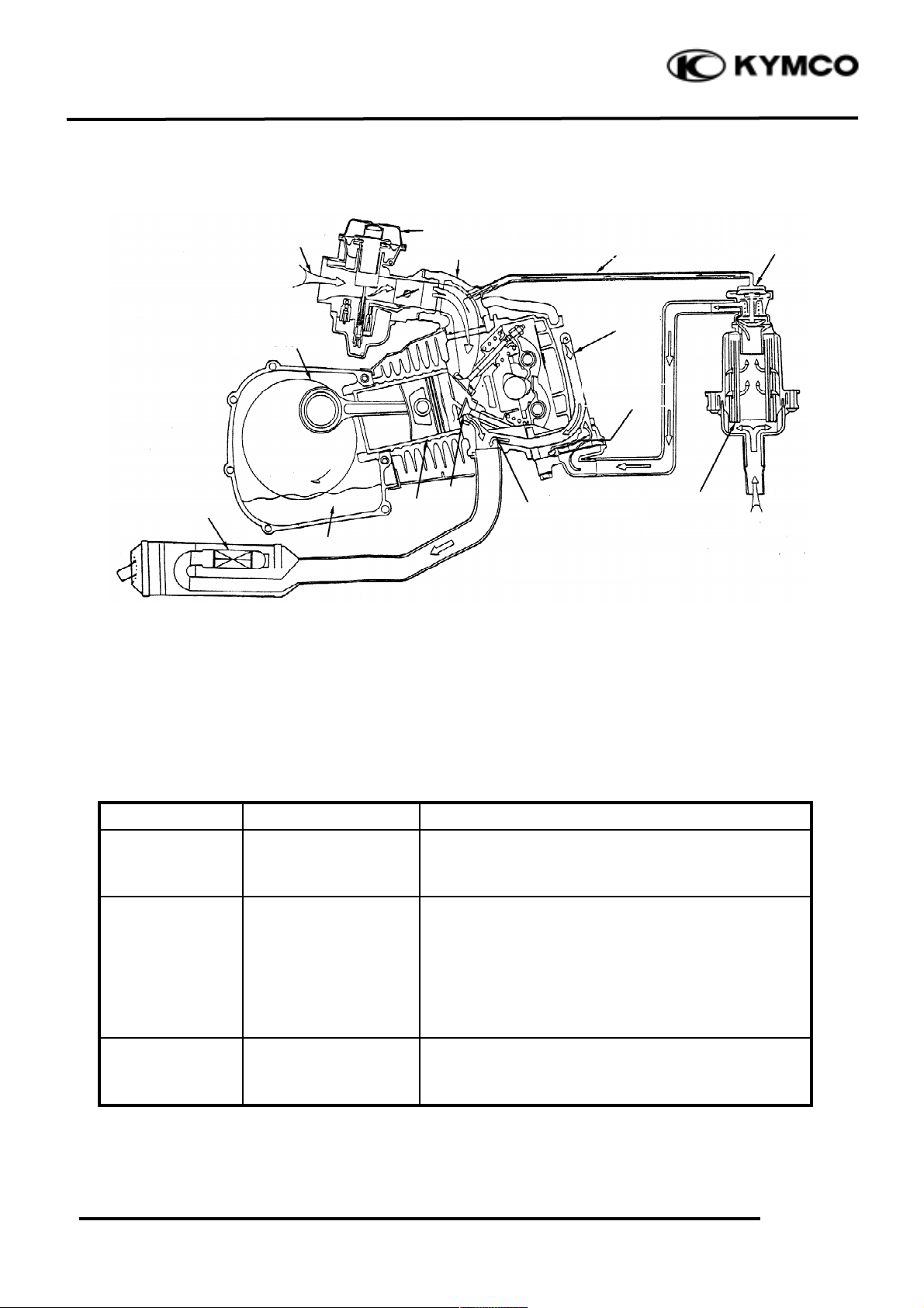
SCHEMATIC DRAWING
EXHAUST EMISSION CONTROL SYSTEM
The exhaust emission control system adopted in this model utilizes the reed valve to draw
secondary air into the exhaust system for re-combustion by means of exhaust pulsation so as to
minimize the exhaust emission.
FUNCTION
Item
Purpose
Function
Secondary Air
Cleaner
Filter secondary air.
It filters the fresh air drawn for re-burning to
prevent dirt or dust from affecting the operation of
the air injection cut-off valve.
Air Injection Cutoff Valve
Prevent exhaust
muffler noise and
backfiring at sudden
deceleration.
The air injection cut-off valve usually opens to lead
air into the exhaust muffler in which air is reburned to reduce CO. When the throttle valve
closes suddenly, the air injection cut-off valve is
actuated by vacuum to close and cut off secondary
air in order to prevent exhaust muffler backfiring
due to air in the exhaust system.
Reed Valve
Control the secondary
air inlet to reduce CO.
When the motorcycle speed is less than 50km per
hour, the reed valve operates to draw secondary air
into the exhaust system for re-combustion.
Secondary
Air Cleaner
Carburetor
Reed Valve
Air Injection
Cut-off Valve
Vacuum
Secondary Air
Cleaner Into
Hole
Page 3

20. EXHAUST EMISSION CONTROL
SYSTEM
20-2
DINK 20 0
TROUBLESHOOTING
High CO at idle speed
1. Damaged or clogged reed valve
2. Damaged or clogged air injection cut-off valve
3. Clogged air cleaner
Backfiring at sudden deceleration
1. Damaged reed valve (malfunction)
2. Faulty air injection cut-off valve (unable to close)
3. Carburetor incorrectly adjusted
4. Faulty air cut-off valve
5. Leaking vacuum tube
Exhaust muffler noise
1. Faulty air injection cut-off valve
2. Broken vacuum tube
3. Faulty reed valve
SERVICE INFORMATION
GENERAL INSTRUCTIONS
• During operation, be careful to avoid scalding caused by the exhaust muffler.
• Note the locations of tubes for proper installation.
• Replace any damaged tube with a new one.
• Make sure to tighten the connector of each tube securely
TOOLS
• Vacuum pump
SPECIFICATIONS
Air injection cut-off valve actuating pressure-
250mm/Hg- 30 liter/min.
Reed valve stopper clearance- 4.6mm
Page 4

20. EXHAUST EMISSION CONTROL
SYSTEM
20-3
DINK 20 0
SECONDARY AIR CLEANER /
AIR INJECTION CUT-OFF
VALVE (A.I.C.V.)
REMOVAL
Remove the seat. (2-4)
Remove the body cover.
Disconnect the secondary air cleaner
/(A.I.C.V) connecting tube.
INSPECTION
Inspect the air injection cut-off valve flow
using a vacuum pump. If the flow is not
within the specified values, replace with a
new one.
The flow should be at least 30 liter/min
when a vacuum of 250mm/Hg is applied.
The flow should be at least 1.6 liter/min
when a vacuum of 320mm/Hg is applied.
Check each connecting tube for cracks or
damage and replace if necessary.
INSTALLATION
The installation sequence is the reverse of
removal.
• The secondary air cleaner must be
assembled and installed properly to
avoid dust entering the air cleaner.
• When installing, be careful not to
bend or twist the tubes and check
for proper installation.
• The tube length is very important to
its performance, use the tube of
same specification for replacement.
*
Air Inlet Tube
Bolt
Secondary Air Cleaner / A.I.C.V.
Air Outlet Tube
Air Inlet Tube
Air Outlet Tube
Bolt
Vacuum Tube
Bolt
Vacuum Tube
Bolt
Page 5

20. EXHAUST EMISSION CONTROL
SYSTEM
20-4
DINK 20 0
REED VALVE
REMOVAL
Remove the frame center cover.
Remove the floor board cover.
Disconnect the secondary air inlet tube
connector.
Remove the reed valve cover three bolts and
two secondary air outlet tube bolts.
Remove the three bolts attaching the reed
valve cover and the reed valve.
INSPECTION
Check the reed valve for cracks, damage, big
clearance or weak reeds. Replace if
necessary.
Check the gasket and O-ring for damage or
deterioration and replace if necessary.
Reed valve stopper clearance: 4.6mm
INSTALLATION
Install the reed valve in the reverse order of
removal.
Cylinder Head Cover
Bolt
Secondary Air Inlet Tube Bolt
Reed Valve
Reed Stopper
Reed Valve Cover
Bolt
• When installing, be careful not to bend
or twist the tubes and check for
proper installation.
*
 Loading...