


 Loading...
Kurzweil PC2
Musician’s Guide
©2000 All rights reserved. Kurzweil is a product line of Young Chang Co.; Kurzweil and PC2 are trademarks of Young Chang Co. All other products and brand names are trademarks or registered trademarks of their respective companies. Product features and specifications are subject to change without notice.
Part Number: 910345 Rev. A
CAUTION
RISK OF ELECTRIC SHOCK
DO NOT OPEN
CAUTION: TO REDUCE THE RISK OF ELECTRIC SHOCK, DO NOT REMOVE THE COVER
NO USER SERVICEABLE PARTS INSIDE
REFER SERVICING TO QUALIFIED SERVICE PERSONNEL
The lightning flash with the arrowhead symbol, within an equilateral triangle, is intended to alert the user to the presence of uninsulated "dangerous voltage" within the product's enclosure that may be of sufficient magnitude to constitute a risk of electric shock to persons.
The exclamation point within an equilateral triangle is intended to alert the user to the presence of important operating and maintenance (servicing) instructions in the literature accompanying the product.
IMPORTANT SAFETY & INSTALLATION INSTRUCTIONS
INSTRUCTIONS PERTAINING TO THE RISK OF FIRE, ELECTRIC SHOCK, OR INJURY TO PERSONS
WARNING: When using electric products, basic precautions should always be followed, including the following:
1.Read all of the Safety and Installation Instructions and Explanation of Graphic Symbols before using the product.
2.Do not use this product near water - for example, near a bathtub, washbowl, kitchen sink, in a wet basement, or near a swimming pool, or the like.
3.This product should be used only with a stand or cart that is recommended by the manufacturer.
4.This product, either alone or in combination with an amplifier and speakers or headphones, may be capable of producing sound levels that could cause permanent hearing loss. Do not operate for a long period of time at a high volume level or at a level that is uncomfortable. If you experience any hearing loss or ringing in the ears, you should consult an audiologist.
5.The product should be located so that its location or position does not interfere with its proper ventilation.
6.The product should be located away from heat sources such as radiators, heat registers, or other products that produce heat.
7.The product should be connected to a power supply only of the type described in the operating instructions or as marked on the product.
8.This product may be equipped with a polarized line plug (one blade wider than the other). This is a safety feature. If you are unable to insert the plug into the outlet, contact an electrician to replace your obsolete outlet. Do not defeat the safety purpose of the plug.
9.The power supply cord of the product should be unplugged from the outlet when left unused for a long period of time. When unplugging the power supply cord, do not pull on the cord, but grasp it by the plug.
10.Care should be taken so that objects do not fall and liquids are not spilled into the enclosure through openings.
11.The product should be serviced by qualified service personnel when:
A.The power supply cord or the plug has been damaged;
B.Objects have fallen, or liquid has been spilled into the product;
C.The product has been exposed to rain;
D.The product does not appear to be operating normally or exhibits a marked change in performance;
E.The product has been dropped, or the enclosure damaged.
12.Do not attempt to service the product beyond that described in the user maintenance instructions. All other servicing should be referred to qualified service personnel.
13.WARNING: Do not place objects on the product’s power supply cord, or place the product in a position where anyone could trip over, walk on, or roll anything over cords of any type. Do not allow the product to rest on or be installed over cords of any type. Improper installations of this type create the possibility of a fire hazard and/or personal injury.
RADIO AND TELEVISION INTERFERENCE
WARNING: Changes or modifications to this instrument not expressly approved by Young Chang could void your authority to operate the instrument.
IMPORTANT: When connecting this product to accessories and/or other equipment use only high quality shielded cables.
NOTE: This instrument has been tested and found to comply with the limits for a Class A digital device, pursuant to Part 15 of the FCC Rules. These limits are designed to provide reasonable protection against harmful interference when the instrument is used in a commercial environment. This instrument generates, uses, and can radiate radio frequency energy and, if not installed and used in accordance with the instruction manual, may cause harmful interference to radio communications. Operation of this instrument in a residential area is likely to cause harmful interference, in which case the user will be required to correct the interference at his or her own expense.
Changes and modifications not expressly approved by the manufacturer
or registrant of this instrument an void the user’s authority to operate this instrument under Federal Communications Commission rules.
In order to maintain compliance with FCC regulations, shielded cables must be used with this instrument. Operation with unapproved equipment or unshielded cables is likely to result in harmful interference to radio and television reception.
NOTICE
This apparatus does not exceed the Class A limits for radio noise emissions from digital apparatus set out in the Radio Interference Regulations of the Canadian Department of Communications.
AVIS
Le present appareil numerique n’emet pas de bruits radioelectriques depassant les limites applicables aux appareils numeriques de la class A prescrites dans le Reglement sur le brouillage radioelectrique edicte par le ministere des Communications du Canada.
SAVE THESE INSTRUCTIONS
ii

Young Chang Distributors
Contact the nearest Young Chang office listed below to locate your local Young Chang/ Kurzweil representative.
Young Chang America, Inc.
P.O. Box 99995
Lakewood, WA 98499-0995
Tel: (253) 589-3200
Fax: (253) 984-0245
Young Chang Co.
178-55 Gajwa-Dong
Seo-Ku, Inchon, Korea 404-714
Tel: 011-82-32-570-1380
Fax: 011-82-32-570-1218
Young Chang Akki Europe GmbH
Industriering 45
D-41751 Viersen
Germany
Tel: 011-49-2162-4491
Fax: 011-49-2162-41744
Young Chang Canada Corp.
250 Shields Court, Unit #11
Markham, Ontario L3R 9W7
Tel: (905) 948-8052
Fax: (905) 948-8172
iii
Contents
Young Chang Distributors ............................................................................................................................................... iii
Chapter 1 Introduction |
|
Basic PC2 Features .......................................................................................................................................................... |
1-1 |
The Sound ................................................................................................................................................................. |
1-1 |
Keyboard and Controllers ...................................................................................................................................... |
1-1 |
Effects......................................................................................................................................................................... |
1-2 |
Options ............................................................................................................................................................................. |
1-2 |
Sound ROM Cards................................................................................................................................................... |
1-2 |
Polyphony Expansion Board.................................................................................................................................. |
1-2 |
Pedals......................................................................................................................................................................... |
1-2 |
Ribbon Controller..................................................................................................................................................... |
1-2 |
Music Rack ................................................................................................................................................................ |
1-2 |
Breath Controller...................................................................................................................................................... |
1-2 |
Unpacking your PC2 ...................................................................................................................................................... |
1-3 |
Chapter 2 Startup |
|
Setup.................................................................................................................................................................................. |
2-1 |
Installing the Music Rack........................................................................................................................................ |
2-1 |
Basic Connections............................................................................................................................................................ |
2-2 |
Power ......................................................................................................................................................................... |
2-2 |
Audio ......................................................................................................................................................................... |
2-3 |
MIDI........................................................................................................................................................................... |
2-4 |
Using the PC2 as a MIDI Master .................................................................................................................... |
2-4 |
Using the PC2 as a MIDI Slave ....................................................................................................................... |
2-4 |
MIDI Out/Thru................................................................................................................................................. |
2-4 |
Pedals......................................................................................................................................................................... |
2-4 |
Breath ......................................................................................................................................................................... |
2-5 |
Ribbon........................................................................................................................................................................ |
2-5 |
Digital Output .......................................................................................................................................................... |
2-6 |
Powering Up .................................................................................................................................................................... |
2-6 |
Display (LCD)........................................................................................................................................................... |
2-6 |
LEDs........................................................................................................................................................................... |
2-6 |
Software Upgrades .................................................................................................................................................. |
2-6 |
Playing the Demo Sequences ................................................................................................................................. |
2-6 |
Troubleshooting........................................................................................................................................................ |
2-7 |
No Text in Display ............................................................................................................................................ |
2-7 |
Low Battery........................................................................................................................................................ |
2-7 |
No Sound ........................................................................................................................................................... |
2-7 |
Chapter 3 Performance Features
In This Chapter ................................................................................................................................................................ |
3-1 |
Overview .......................................................................................................................................................................... |
3-1 |
Modes ........................................................................................................................................................................ |
3-1 |
Editors ................................................................................................................................................................ |
3-2 |
The Internal Setup.................................................................................................................................................... |
3-2 |
|
|

Kurzweil PC2 Musician’s Guide
Contents |
|
Effects and EQ .......................................................................................................................................................... |
3-2 |
Physical Controllers................................................................................................................................................. |
3-3 |
The Front Panel................................................................................................................................................................ |
3-3 |
Common Features.................................................................................................................................................... |
3-4 |
Master Volume Slider ....................................................................................................................................... |
3-4 |
Data Entry .......................................................................................................................................................... |
3-4 |
System................................................................................................................................................................. |
3-4 |
Effects.................................................................................................................................................................. |
3-5 |
Functions............................................................................................................................................................ |
3-5 |
Sound Source..................................................................................................................................................... |
3-5 |
Mode-Dependent Features ..................................................................................................................................... |
3-6 |
The Display (LCD)............................................................................................................................................ |
3-6 |
Cursor Buttons .................................................................................................................................................. |
3-8 |
Sound Parameters............................................................................................................................................. |
3-8 |
Zone Parameters ............................................................................................................................................... |
3-8 |
Sound/Setup Select .......................................................................................................................................... |
3-8 |
Zone Select and Assignable Controllers ........................................................................................................ |
3-9 |
Selecting Programs and Setups ................................................................................................................................... |
3-13 |
Other Selection Methods....................................................................................................................................... |
3-13 |
Internal Voices Mode and KB3 Mode .......................................................................................................... |
3-13 |
MIDI Setups Mode.......................................................................................................................................... |
3-13 |
EQ .................................................................................................................................................................................... |
3-14 |
Changing the EQ.................................................................................................................................................... |
3-14 |
Effects.............................................................................................................................................................................. |
3-14 |
Activating Effects ................................................................................................................................................... |
3-14 |
Changing Effects .................................................................................................................................................... |
3-15 |
Muting Effects......................................................................................................................................................... |
3-15 |
Wet/Dry Mix .......................................................................................................................................................... |
3-16 |
Layering and Splitting.................................................................................................................................................. |
3-17 |
Using AutoSplit for Quick Layers and Splits..................................................................................................... |
3-17 |
How AutoSplit Works ........................................................................................................................................... |
3-18 |
Saving Quick Layers and Splits ........................................................................................................................... |
3-18 |
Changing the AutoSplit Key Without Editing................................................................................................... |
3-19 |
Saving the AutoSplit Key...................................................................................................................................... |
3-19 |
Muting and Soloing ...................................................................................................................................................... |
3-19 |
Muting ..................................................................................................................................................................... |
3-20 |
Soloing ..................................................................................................................................................................... |
3-20 |
The AutoSplit Feature............................................................................................................................................ |
3-20 |
Saving the Internal Setup............................................................................................................................................. |
3-21 |
Digital Audio Output ................................................................................................................................................... |
3-21 |
Chapter 4 Programming Your PC2
Basic Editing Concepts ................................................................................................................................................... |
4-1 |
Overview................................................................................................................................................................... |
4-1 |
Beginning to Edit...................................................................................................................................................... |
4-1 |
Navigation ......................................................................................................................................................... |
4-1 |
Data Entry .......................................................................................................................................................... |
4-2 |
Naming and Storing ......................................................................................................................................... |
4-2 |
Other Save-Dialog Functions ................................................................................................................................. |
4-3 |
Restoring Factory Effects ................................................................................................................................. |
4-3 |
Deleting Objects ................................................................................................................................................ |
4-3 |
vi

|
Kurzweil PC2 Musician’s Guide |
|
Contents |
Dumping Objects .............................................................................................................................................. |
4-4 |
Intuitive Entry .......................................................................................................................................................... |
4-5 |
Short Cuts for Data Entry ................................................................................................................................ |
4-5 |
Short Cuts for Navigation................................................................................................................................ |
4-6 |
Other Editing Functions.......................................................................................................................................... |
4-7 |
Comparing ......................................................................................................................................................... |
4-7 |
Copying and Pasting ........................................................................................................................................ |
4-8 |
More About SysEx Dumps ..................................................................................................................................... |
4-9 |
SysEx IDs............................................................................................................................................................ |
4-9 |
Dumping the Entire Memory.......................................................................................................................... |
4-9 |
The Program Editor ...................................................................................................................................................... |
4-10 |
Program Editing Basics ......................................................................................................................................... |
4-10 |
Entering the Program Editor......................................................................................................................... |
4-10 |
The Current Layer............................................................................................................................................ |
4-11 |
Keymaps............................................................................................................................................................ |
4-11 |
Muting and Soloing Layers ............................................................................................................................ |
4-11 |
Storing Effects.................................................................................................................................................. |
4-12 |
Beyond the Basics................................................................................................................................................... |
4-12 |
The Setup Editor............................................................................................................................................................ |
4-12 |
The Default Setup and the Clear Setup ....................................................................................................... |
4-13 |
Entering the Setup Editor ..................................................................................................................................... |
4-13 |
Creating Setups ...................................................................................................................................................... |
4-13 |
Setting Initial Volume Levels for Different Zones............................................................................................. |
4-14 |
Assigning Sliders to Control Wet/Dry Mix in Different Zones ...................................................................... |
4-15 |
Assigning Entry Values......................................................................................................................................... |
4-15 |
A Few Important Points About Entry Values ............................................................................................. |
4-16 |
Multiple Controller Function ............................................................................................................................... |
4-17 |
Offset vs. Scale................................................................................................................................................. |
4-18 |
Crossfades ............................................................................................................................................................... |
4-18 |
Velocity Switching.................................................................................................................................................. |
4-19 |
Velocity Layering ................................................................................................................................................... |
4-19 |
Switching Setups With a Pedal ............................................................................................................................ |
4-19 |
Transposing a Setup With a Button ..................................................................................................................... |
4-20 |
The KB3 Editor.............................................................................................................................................................. |
4-20 |
Editing the Percussion Parameters...................................................................................................................... |
4-20 |
The Effects Editor .......................................................................................................................................................... |
4-21 |
Effects Change Mode............................................................................................................................................. |
4-21 |
Setting the Effects Change Mode.................................................................................................................. |
4-21 |
Entering the Effects Editor.................................................................................................................................... |
4-22 |
Selecting Different Effects ..................................................................................................................................... |
4-22 |
Editing Effects Parameters.................................................................................................................................... |
4-23 |
KB3 Effects ....................................................................................................................................................... |
4-23 |
Saving Effects.......................................................................................................................................................... |
4-23 |
Other Effects-Editor Functions............................................................................................................................. |
4-25 |
Common Editing Tasks ................................................................................................................................................ |
4-25 |
Making Effects Active at Program or Setup Selection ...................................................................................... |
4-25 |
Turning AutoSplit On and Off ............................................................................................................................. |
4-25 |
Controlling Vibrato and Tremolo with LFOs ..................................................................................................... |
4-26 |
Using Mono Audio Output .................................................................................................................................. |
4-26 |
Changing Preset Drawbar Values........................................................................................................................ |
4-26 |
Making Drawbars Live .................................................................................................................................. |
4-26 |
Changing the Values of Preset Drawbars.................................................................................................... |
4-26 |
vii

Kurzweil PC2 Musician’s Guide
Contents |
|
Editing the Internal Setup..................................................................................................................................... |
4-27 |
Using the Arpeggiator .................................................................................................................................................. |
4-27 |
Using Pressure (Aftertouch) as an Arpeggiator Controller ............................................................................. |
4-29 |
Using the Arpeggiator with a Sequencer or External Controller.................................................................... |
4-29 |
Using the PC2 to Control External Slaves ................................................................................................................. |
4-30 |
Sending Bank-Select and Program-Change Messages ..................................................................................... |
4-30 |
Understanding Bank-Select Controllers ............................................................................................................. |
4-30 |
Sending Program Changes Only ......................................................................................................................... |
4-32 |
Preventing Program Changes on Slaves............................................................................................................. |
4-33 |
Working With an External Sequencer ........................................................................................................................ |
4-33 |
Turn Local Control Off! ......................................................................................................................................... |
4-33 |
Global Method................................................................................................................................................. |
4-33 |
Setup Method .................................................................................................................................................. |
4-33 |
Recording to a Sequencer While in MIDI Setups Mode................................................................................... |
4-34 |
Troubleshooting............................................................................................................................................................. |
4-34 |
Chapter 5 Descriptions of Parameters
Program Editor Parameters ........................................................................................................................................... |
5-1 |
The Timbre Menu..................................................................................................................................................... |
5-1 |
The Envelope Menu................................................................................................................................................. |
5-3 |
The LFO Menu.......................................................................................................................................................... |
5-3 |
The LFO Menu: Rotor Effects Parameters............................................................................................................ |
5-4 |
Setup Editor Parameters................................................................................................................................................. |
5-5 |
The MIDI Xmit Menu .............................................................................................................................................. |
5-5 |
The Program Menu.................................................................................................................................................. |
5-6 |
The Key Range Menu .............................................................................................................................................. |
5-9 |
The Transpose Menu ............................................................................................................................................. |
5-10 |
The Velocity Menu ................................................................................................................................................. |
5-10 |
The Controllers Menu............................................................................................................................................ |
5-14 |
The Controllers Menu: Continuous Controller Parameters............................................................................. |
5-15 |
The Controllers Menu: Ribbon Controller Parameters..................................................................................... |
5-16 |
The Controllers Menu: Switch Controller Parameters ..................................................................................... |
5-17 |
Switch-Button Priority ................................................................................................................................... |
5-18 |
The Arpeggiator Menu.......................................................................................................................................... |
5-19 |
Effects Editor Parameters............................................................................................................................................. |
5-24 |
KB3 Editor Parameters ................................................................................................................................................. |
5-27 |
The Timbre Menu................................................................................................................................................... |
5-27 |
The Envelope Menu............................................................................................................................................... |
5-28 |
The Envelope Menu: Percussion Parameters..................................................................................................... |
5-29 |
Envelope Menu: Percussion Pitch Parameters .................................................................................................. |
5-30 |
The LFO Menu........................................................................................................................................................ |
5-30 |
System Parameters ........................................................................................................................................................ |
5-30 |
The Global Menu.................................................................................................................................................... |
5-30 |
The MIDI Recv Menu ............................................................................................................................................ |
5-36 |
Appendix A Maintenance and Upgrades
Replacing the Battery..................................................................................................................................................... |
A-1 |
Before you Begin ..................................................................................................................................................... |
A-1 |
Opening your PC2 .................................................................................................................................................. |
A-1 |
Installing the Battery .............................................................................................................................................. |
A-1 |
viii

|
Kurzweil PC2 Musician’s Guide |
|
Contents |
Replacing the Option Panel................................................................................................................................... |
A-3 |
Powering up............................................................................................................................................................. |
A-3 |
Boot Block........................................................................................................................................................................ |
A-3 |
Starting the Boot Block ........................................................................................................................................... |
A-3 |
About Software Upgrades ..................................................................................................................................... |
A-3 |
Setting Up For a Software Upgrade ..................................................................................................................... |
A-4 |
Installing an Operating System or Setups ........................................................................................................... |
A-4 |
Installing a New Boot Block .................................................................................................................................. |
A-4 |
Installing Sound ROM Options............................................................................................................................. |
A-5 |
Resetting the PC2 .................................................................................................................................................... |
A-5 |
Running the Diagnostics........................................................................................................................................ |
A-5 |
Appendix B Reference
Specifications ................................................................................................................................................................... |
B-1 |
Physical Specifications............................................................................................................................................. |
B-1 |
Electrical Specifications........................................................................................................................................ |
B-1 |
Voltage and Frequency Ranges....................................................................................................................... |
B-1 |
Power Consumption......................................................................................................................................... |
B-1 |
Environmental Specifications................................................................................................................................. |
B-2 |
Audio Specifications ............................................................................................................................................. |
B-2 |
Line-Level Left and Right Analog Audio Outputs ...................................................................................... |
B-2 |
Digital Audio Output ................................................................................................................................... |
B-2 |
Headphone Output .......................................................................................................................................... |
B-2 |
Parameter Reference ....................................................................................................................................................... |
B-3 |
PC2 Audio Signal Routing ............................................................................................................................................. |
B-8 |
MIDI Controllers ............................................................................................................................................................. |
B-9 |
Special Controllers .......................................................................................................................................................... |
B-9 |
KB3 Controllers ............................................................................................................................................................. |
B-10 |
PC2 Keymaps................................................................................................................................................................. |
B-11 |
PC2 Effects and Effects Parameters ............................................................................................................................ |
B-12 |
Reverb...................................................................................................................................................................... |
B-12 |
Delay ........................................................................................................................................................................ |
B-13 |
Chorus...................................................................................................................................................................... |
B-13 |
Flange....................................................................................................................................................................... |
B-14 |
Phase ........................................................................................................................................................................ |
B-14 |
Chorus + Delay....................................................................................................................................................... |
B-14 |
Chorus + Reverb..................................................................................................................................................... |
B-15 |
Chorus + Delay + Reverb...................................................................................................................................... |
B-15 |
Flange + Delay........................................................................................................................................................ |
B-15 |
Flange + Reverb...................................................................................................................................................... |
B-15 |
Flange + Delay + Reverb....................................................................................................................................... |
B-16 |
Flange and Other.................................................................................................................................................... |
B-16 |
Filters ....................................................................................................................................................................... |
B-16 |
Laserverb................................................................................................................................................................. |
B-16 |
Distortion................................................................................................................................................................. |
B-17 |
Enhancer.................................................................................................................................................................. |
B-17 |
Compressor............................................................................................................................................................. |
B-17 |
Simple Motion ........................................................................................................................................................ |
B-17 |
Spatial ...................................................................................................................................................................... |
B-17 |
Rotary Speaker ....................................................................................................................................................... |
B-18 |
MIDI Implementation Chart........................................................................................................................................ |
B-19 |
ix

Kurzweil PC2 Musician’s Guide
Contents
Appendix C PC2 Programs and Controller Assignments
Factory Controller Assignments |
...................................................................................................................................C-1 |
Programs and Controllers.............................................................................................................................................. |
C-1 |
Index ..................................................................................................................................................................................... |
I-1 |
Index of Parameters............................................................................................................................................. |
IP-1 |
x
Chapter 1
Introduction
Thanks for buying your PC2 MIDI performance controller! It combines 16 megabytes of renowned Kurzweil ROM sounds with an extensive set of flexible and easy-to-use performance and MIDI-control features—all in a portable keyboard that can help you sound like a pro on stage or in the studio. We hope you like it.
Basic PC2 Features
The Sound
The PC2 offers 64-voice polyphony that’s expandable to 128 voices. For maximum flexibility in connecting to sound systems and processing or recording equipment, the PC2 provides analog and digital audio outputs, which you can use simultaneously.
There are 128 factory programs, including Kurzweil’s new stereo triple-strike Grand Piano, Rhodes and Wurlitzer electric pianos, stereo strings, brass, and Take 6 vocal samples—as well as our critically-acclaimed keyboard, guitar, bass, drums, and percussion sounds. There’s also room for two Sound ROM Option cards, for up to 48 megabytes of ROM sounds.
Setups make the PC2 a versatile performance instrument and MIDI control keyboard. Each setup contains four zones that can cover any part of the keyboard, or overlap across the entire keyboard. You can program each zone independently—with different programs, physical controller assignments, and MIDI channels for each zone. Using the onboard arpeggiator, you can program setups with grooves that start automatically and evolve in countless variations as you play.
For serious Hammond organ fans we offer KB3 Mode, which uses tone-wheel synthesis to provide superb recreations of the classic B-3 sound—including real-time drawbar controls and multi-effects settings that include all of the essential features of a Hammond-Leslie setup— percussion, key click, chorus and vibrato, tube amp distortion, and rotary speakers with programmable speed control that ramps up and down like the real thing. You can play KB3 programs by themselves or with other programs in setups.
Keyboard and Controllers
There are two PC2 models. Both have the same features, with only one exception. The PC2X has a fully-weighted 88-key piano action, while the standard PC2 has a 76-key lightly-weighted action for the perfect combination of power and portability. Both models have mono pressure (aftertouch), and have programmable velocity sensitivity. (By the way, whenever we mention the PC2 by name, we’re referring to both models.)
You’ll find the usual array of physical controllers—Pitch Wheel, Mod Wheel, jacks for continuous and switch pedal jacks, and a breath-controller jack—as well as multi-function front-panel buttons and sliders, and a unique ribbon controller. They’re all fully programmable.
There’s an extensive list of programmable features for MIDI control—the PC2 isn’t just a greatsounding performance keyboard; it’s a serious tool for MIDI sequencing, and makes an excellent

Introduction
Options
centerpiece for sophisticated MIDI studios. The PC2 is also well-equipped to receive MIDI from other instruments or external MIDI sources like computer-based sequencers.
Effects
To complement the ROM sounds, there are over 150 multiple effects and 30 reverbs. You can apply the effects to programs or setups, and you can easily control the wet/dry mix in real time. You can also program the multi-effects and reverbs for even more control in performance and recording.
Options
Ask your Kurzweil dealer about the following PC2 options:
Sound ROM Cards
The PC2 has sockets for two ROM expansion cards that you can install yourself (the expansion kits come with complete instructions). Each expansion card adds 16 megabytes of ROM sounds to the 16 megabytes of onboard ROM.
Polyphony Expansion Board
There’s a kit for expanding your PC2’s polyphony from 64 voices to 128 voices. You can install this kit yourself as well.
Pedals
The PC2 has jacks for three switch pedals (for functions like sustain or program/setup changes) and two continuous pedals (for functions like volume control). Your Kurzweil dealer stocks the following optional pedals:
FS-1 |
Standard box-shaped switch pedal |
KFP-1 |
Single piano-style switch pedal |
KFP-2M |
Double piano-style switch pedal unit |
CC-1 |
Continuous pedal |
Ribbon Controller
There’s a dedicated modular jack (like a telephone jack) on the rear panel for connecting this 600-mm (24-inch) ribbon controller. You can configure the PC2 to use the ribbon as a single large controller, or a three-section controller with independent settings for each section.
Music Rack
The sturdy acrylic music rack (model PC-MDS) fits into a bracket that you attach to the PC2’s rear panel. You’ll find installation instructions on page 2-1.
Breath Controller
You can plug a Yamaha (or equivalent) breath controller into the dedicated jack on the PC2’s rear panel (your Kurzweil dealer won’t necessarily have these in stock).
1-2

Introduction
Unpacking your PC2
Unpacking your PC2
Your PC2 carton should contain the following:
•PC2 or PC2X Performance Controller
•Power adapter
•Piano-style switch pedal
•Four adhesive-backed rubber feet
•This manual
•Warranty card
You might want to keep the PC2 carton and packing materials for easy shipping or transport.
1-3
Chapter 2
Startup
Setup
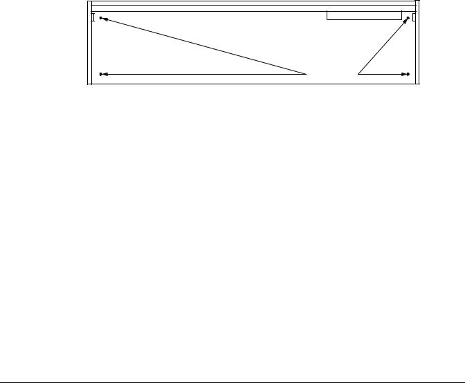
When setting up the PC2 for use it must be placed on a sturdy, level surface where both ends of the unit are supported. A conventional keyboard stand may be used if it is strong enough to support the unit’s weight (about 35 pounds for a PC2, 50 for a PC2X). If you are going to be using the unit on a table now or in the future, apply the four stick-on rubber feet to the bottom. Figure 2-1 shows the recommended locations marked with pairs of small guide holes. Remove the backing paper from each rubber foot and attach just forward of each set of guide holes. It is possible that these locations could interfere with some keyboard stand’s supports, so check how the PC2 fits on your stand before applying the rubber feet.
Attach feet here |
Figure 2-1 Attaching rubber feet
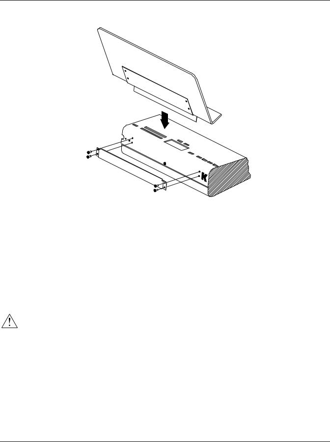
Installing the Music Rack
You’ll need a Phillips screwdriver to install the optional music rack.
1.Remove the four screws on the rear panel of the PC2, as shown in Figure 2-2.
2.Use the screws to attach the music rack bracket, making sure that the rounded edge of the bracket is at the top.
3.Slide the music rack in from the top (as shown in the figure).
Startup
Basic Connections
Figure 2-2 Installing the music rack
Basic Connections
Power
The PC2 has an external transformer/power supply with a standard electrical plug on one end, and a keyed four-pin plug that connects with the PC2 (keyed means that there’s only one way to connect it). This is a specialized power supply, and is not interchangeable with other power supplies.
Caution: Use only the power supply that comes with your PC2, or a replacement purchased from an authorized Kurzweil dealer. Using a different power supply can seriously damage your PC2!
Before connecting the power supply, make sure your PC2 is off (push the side of the power switch that’s marked with a circle). Connect the keyed plug to the AC In connector. Figure 2-3 shows the correct orientation of the plug.
2-2

Startup
Basic Connections
Key
Flat side down!
Figure 2-3 Proper orientation of plug
Place the power supply somewhere where it will stay dry and out of the way. We recommend keeping it on the floor. Never cover the power supply with anything; it needs adequate ventilation to prevent overheating.
Connect the plug at the other end of the power-supply cable into a standard power outlet. If you plan to take your PC2 to a location that uses a different voltage level, you’ll need to get an additional power supply that’s compatible with the local voltage.
Audio
The PC2 features balanced left and right analog audio outputs with 1/4-inch jacks. For best results, use balanced cables to connect to balanced, line-level inputs on your mixer or sound system.
It’s important to use shielded, twisted-pair cables. The cables should each have 1/4-inch stereo (tip-ring-sleeve) plugs on one end to connect to the PC2. The other end of each cable should have either 1/4-inch stereo plugs or XLR plugs. Cables of this type provide balanced operation, which greatly reduces many types of noise. Unbalanced cables or sound-system inputs won’t give you quite the same audio quality.
For best performance, set the PC2’s Master Volume slider to its maximum when adjusting mixer or sound-system levels. Otherwise, if you adjust the PC2’s level by increasing the level of your sound system, you’ll increase the noise level.
If you’re using a monaural sound system or running the PC2’s audio into a single mixer channel, we recommend configuring the PC2 for mono output, in which case the PC2 sends the same one-channel signal to the left and right sides of both the analog and digital outputs. See page 4-26 for information about using mono audio output mode.
The PC2 has a headphone jack, which carries the same signal as the main outputs (that’s true whether you’re using stereo or mono output). The headphone jack accepts a standard 1/4-inch stereo plug, and is compatible with nearly all types of headphones. Plugging into the headphones jack does not mute the other audio outputs.
You can also use the headphone jack as an unbalanced stereo line-level output. Just connect a stereo cable from the headphone jack to a stereo input on your mixer or sound system. If you have only unbalanced inputs to your sound system, you’ll get better audio quality using the headphone jack.
There’s also an RCA digital audio jack, which you can use in addition to the analog outputs. See page 2-6 for more information.
2-3

Startup
Basic Connections
MIDI
The PC2 both transmits and accepts most standard (and several specialized) MIDI messages. In other words, it can serve as both a MIDI master and a MIDI slave.
Using the PC2 as a MIDI Master
Connect a MIDI cable from the MIDI Out port of the PC2 to the MIDI In port of the device you want to control—another MIDI musical instrument, or any device that accepts MIDI, such as a computer with a MIDI interface or an integrated MIDI In port. This makes the PC2 a MIDI control device, and you can use it to play other instruments, make recordings using sequencers, or send MIDI System Exclusive (SysEx) messages for storing programs, setups, and effects settings externally.
When the PC2 is the MIDI master, you can configure it to control only its slaves, or to play its own sounds in addition to controlling the slaves.
Using the PC2 as a MIDI Slave
Connect a MIDI cable from the MIDI Out port of the instrument or device that you’re using as the MIDI master to the MIDI In port of the PC2. This makes the PC2 a MIDI slave, enabling you to play its sounds from any MIDI instrument—keyboard, wind controller, drum pads, whatever—or to control it via MIDI devices like dedicated sequencers or computers running sequencing applications. The PC2 can receive 16 independent channels of MIDI information.
MIDI Out/Thru
This jack has two functions: it can be a MIDI Out port, enabling you to send directly to two different slaves, or it can be a MIDI Thru port, in which case it passes along whatever MIDI information that the PC2 receives at its MIDI In port (but not the MIDI information that the PC2 itself generates). This makes it easy to include the PC2 in a chain of multiple MIDI devices, which is a common configuration when you’re using a computer for sequencing.
There’s a small switch labeled Thru/Out on the PC2’s rear panel (as you face the rear panel, the switch is to the left of the MIDI In port). Use a small pointed object to set the switch to the position you want—a ball-point pen works nicely.
Pedals
Plug your switch or continuous pedals into the corresponding jacks on the PC2’s rear panel. We recommend using the Kurzweil pedals described on page 1-2, but you can use almost any switch or continuous pedal, as long as it adheres to the following specifications (as most pedals do):
Switch pedals |
1/4-inch tip-sleeve plug |
Continuous pedals |
10-kOhm linear-taper potentiometer, 1/4-inch tip-ring-sleeve plug |
If you use a third-party (non-Kurzweil) switch pedal, make sure it’s connected before you turn on your PC2. This ensures that the pedal will work properly (it might function backward—off when it’s down and on when it’s up—if you turn on your PC2 before plugging in the pedal).
Similarly, don’t press any of your switch pedals while powering up, because the PC2 verifies each pedal’s orientation during power up. If you’re pressing a pedal, you might cause it to work backward.
2-4

Startup
Basic Connections
The pedals are independently programmable within each zone of every setup. Here are the default settings for the five pedals you can use with the PC2:
Switch Pedal 1 |
Controller 64 |
(Sustain) |
Switch Pedal 2 |
Controller 66 |
(Sostenuto) |
Switch Pedal 3 |
Controller 67 |
(Soft) |
Continuous Control Pedal 1 |
Controller 11 (Expression) |
|
Continuous Control Pedal 2 |
Controller 4 (Foot Pedal) |
|
Breath
The 3.5mm Breath jack labeled Breath accepts a standard breath controller, which sends standard MIDI Breath (MIDI 2) messages. The PC2’s preset programs and setups don’t respond to breath, but if you have other instruments that do respond to Breath, you can control them from the PC2 via MIDI.
You can also program the PC2 so that the breath controller sends a different MIDI message. This would enable you to use a breath controller to affect the PC2, but then other instruments receiving MIDI from the PC2 would no longer respond to the PC2’s breath controller (unless you also programmed them to receive the same MIDI Controller that the PC2’s breath controller is sending).
Ribbon
Connect the optional Kurzweil Ribbon Controller into the modular Ribbon jack on the rear panel. The ribbon controller itself should rest on a flat surface; it fits nicely between the keys and the buttons and sliders on the front panel.
The ribbon is a continuous controller. You can program the ribbon controller to send MIDI Controller messages 1–127, as well as several specialized messages. It generates values of 0–127 for whatever MIDI Controllers you assign it to send. Just press it, and slide your finger along the ribbon to change the value of the message it’s sending.
You can configure the ribbon to have one control section that runs its entire length, or to have three sections of equal length. It sends its highest values when you press it at the end where the cable connects. When you configure it to have three sections, each section sends its highest values at the end closest to the cable.
The ribbon controller comes with an adhesive-backed foam strip and Velcro® fastener pads. The foam strip will hold it in place under most circumstances, but you might find it more convenient to attach it more securely with the Velcro fasteners. In that case, we recommend sticking the hook side of each pad to the underside of the Ribbon and the loop (softer) side to the keyboard. This helps to prevent the hooks in the Velcro from collecting crud when you don’t have the ribbon attached.
Caution: The modular jack is designed for connection to the Kurzweil Ribbon Controller option only. Don’t plug any other modular plugs into the Ribbon jack.
2-5

Startup
Powering Up
Digital Output
With the PC2, you can take advantage of the growing number of digital recorders and mixers on the market. Connect a 75-Ohm coaxial cable from the PC2’s RCA Digital Out jack to the AES or S/PDIF input of the receiving device. You may need an RCA-to-XLR adapter to connect with the receiving device. If the receiving device receives only optical signals, you’ll need a converter as well.
Powering Up
When you’ve made all your connections, turn on the PC2 by pushing the side of the power switch marked with the vertical line. All of the lights on the front panel flash, and the liquidcrystal display (LCD) shows a series of messages. When the PC2 is ready to play, the display looks like this:
Bank:0||Internal||1A
000|Stereo|Grand|
Before playing, we recommend that you slide the volume control nearly to the bottom and gradually push the control up while playing the keyboard. This way you won’t cause any pain or damage if there’s too much gain in your sound system.
Display (LCD)
The PC2’s 40-character liquid-crystal display tells you what’s going on, whether you’re playing or editing. Depending on your viewing angle (and possibly the temperature), you may need to adjust the contrast for better visibility. There’s a small black knob on the rear panel, between the MIDI ports and the Digital Out jack. Use a screwdriver or your fingertips to turn the knob until you can read the display easily.
LEDs
Most of the buttons on the PC2’s front panel contain light-emitting diodes that indicate the status of the features that the buttons control. They should all flash red three times as the PC2 starts up.
Software Upgrades
The PC2 contains a type of reloadable computer memory called Flash ROM, which makes software upgrades fast and easy. You can learn about new features from your Kurzweil dealer, or from our website (www.youngchang.com/kurzweil). See Boot Block on page A-3 for softwareinstallation instructions.
Playing the Demo Sequences
1.Press Sound Select buttons 14 and 16 (Bass and Percussion) simultaneously to enter Demo mode. Sound Select buttons 1–4 blink (more than four of these buttons will blink if you’ve added one or both of the Sound ROM expansion cards). Each button starts a different demo sequence when you press it. If you want to stop the demo before it finishes, press 14 and 16 simultaneously again.
2.When the demo finishes (or when you stop it), buttons 1–4 start blinking again.
2-6
Startup
Powering Up
3.Select another demo, or press Cancel to exit Demo mode (alternatively, you can press 14 and 16 simultaneously).
Troubleshooting
No Text in Display
If no messages are displayed when you turn on the power on your PC2 and no LEDs flash, check the power adapter connections at the AC outlet and the PC2 Adapter In jack.
Low Battery
When you turn your PC2 off, a lithium battery protects the memory that the PC2 uses to store user-defined programs and setups, and other editing changes that you’ve saved. Every time you turn on your PC2, it automatically checks the battery voltage. If it’s getting low, you’ll see a message like this before the PC2 finishes starting up:
|Battery|voltage|is
||low|(2.7|volts)
When you see this message, you should replace your battery immediately, to avoid losing your data. See page A-1 for instructions.
No Sound
If no sound comes from the audio or headphones outputs of your PC2 when you play the keyboard, check the following:
•The Volume slider might be set too low
•There’s no current program or setup selected (the display shows Not|Found )
•Continuous control pedal 1: check the connection, and check the position of the pedal
•You might be in MIDI Setups mode with all zones muted (inactive): press any or all of the four buttons labeled Zone 1–Zone 4, and the lights in the buttons will turn green
•Local control might be off: press the Global button, then turn the large knob in the Data Entry region of the front panel one click to the right
•The PC2 might be sending to MIDI only: press the MIDI Xmit button in the Zone Parameters region of the front panel, then press the right-arrow button under the display once, then turn the large knob in the Data Entry region until you see Local or Local+MIDI
2-7

Startup
Powering Up
No Sound from Receiving Instrument
If you are trying to control another instrument using MIDI and that instrument doesn’t respond to your PC2, check the following:
•A working MIDI cable should connect the PC2’s Out or Thru/Out jack to the In jack of the other instrument
•If you’re using the MIDI Thru/Out port, flip the switch near the MIDI In port to the out position (a ball-point pen works well for this)
•Continuous control pedal 1: check the connection and pedal position
•The other instrument should be receiving on the same MIDI channel that the PC2 is using to transmit MIDI information
•All zones that you want to transmit must be active (the lights in the Zone 1–Zone 4 buttons must be green)
•The PC2 might be sending MIDI information only to itself: press the MIDI Xmit button in the Zone Parameters region of the front panel, then press the right-arrow button under the
display once, then turn the large knob in the Data Entry region until you see MIDI or
Local+MIDI
2-8

Chapter 3
Performance Features
In This Chapter
Chapter 3 shows you how to get the most out of your PC2 in performance settings. The overview introduces a few important features and concepts, while the following sections provide more detail.
• The Front Panel. . . . . . . . . . . . . . . . . . . . . . . . . . . . . . . . . . . . . . . 3-3
• Selecting Programs and Setups . . . . . . . . . . . . . . . . . . . . . . . . 3-13
• EQ . . . . . . . . . . . . . . . . . . . . . . . . . . . . . . . . . . . . . . . . . . . . . . . . . 3-14
• Effects . . . . . . . . . . . . . . . . . . . . . . . . . . . . . . . . . . . . . . . . . . . . . . 3-14
• Layering and Splitting . . . . . . . . . . . . . . . . . . . . . . . . . . . . . . . . 3-17
• Muting and Soloing . . . . . . . . . . . . . . . . . . . . . . . . . . . . . . . . . . 3-19
• Saving the Internal Setup . . . . . . . . . . . . . . . . . . . . . . . . . . . . . 3-21
• Digital Audio Output. . . . . . . . . . . . . . . . . . . . . . . . . . . . . . . . . 3-21
Overview
Modes
The PC2 has three performance modes: Internal Voices, MIDI Setups, and KB3. Select the performance mode by pressing the corresponding button in the Sound/Setup Select region.
Internal Voices mode lets you play one internal voice, or program, at a time. A program consists of a single sound (like piano or strings), and the settings that affect that sound (like which part of the keyboard it uses). The PC2 starts in Internal Voices mode when you turn it on.
MIDI Setups mode is what makes the PC2 such a powerful MIDI controller. In this mode you can play one setup at a time. A setup divides the PC2’s keyboard into four zones, each of which can cover part or all of the keyboard. Each zone can use a different MIDI channel and play a different program. Each zone can also have its own controller assignments; for example, the Mod Wheel can do something different in each zone of a setup.
In KB3 mode, the PC2 uses a different synthesizer technique (tone wheel emulation) to reproduce the sound of classic tone-wheel organs (like the Hammond B-3). In most other respects, KB3 mode is like Internal Voices mode.

Performance Features
Overview
Objects
Throughout this manual, we’ll occasionally mention objects, which may sound a bit technical, so we’ll explain. Object is the collective term we use to refer to any chunk of information that the PC2 stores or processes. Many of these objects are invisible to you, but you’ll be working regularly with the highest-level object types: programs, setups, and effects. When you’re editing programs, there’s a good chance you’ll work with another important object type: keymaps. You might also use System Exclusive (SysEx) messages to store programs, setups or effects to an external device—or use a single SysEx message to store all the objects you’ve modified while editing.
Editors
In addition to the performance modes, there’s also a series of editing modes, where you can make changes that affect each of the performance modes (or the entire PC2). Turn to Chapter 4 for details about editing.
The Internal Setup
The three performance modes are quite different from a musician’s viewpoint. The most noticeable difference is the way the liquid-crystal display (LCD) looks in each mode, as you’ll learn on page 3-6.
Behind the scenes, however, the performance modes aren’t as different as they seem. In fact, they have quite a bit in common. For example, consider that familiar controller the Pitch Wheel. Push it up and you bend notes up; pull it down and you bend notes down. This works in all three performance modes.
The Pitch Wheel does what it does because the PC2 is programmed that way—but you could program it for other functions if you wanted. In a setup, the Pitch Wheel can do something different in each zone—and that’s true for all the assignable physical controllers: Mod Wheel, sliders, pedals, and more.
In a program (Internal Voices mode or KB3 mode), things are different. From the viewpoint of you the musician, programs don’t have zones, so each physical controller can do only one thing, but it’s up to you to decide what each physical controller does. That information gets stored in the internal setup, which has only one zone, but is otherwise exactly like a setup in MIDI Setups mode.
Every program in Internal Voices mode uses the internal setup to determine the assignments of the physical controllers—and many other characteristics. Programs in KB3 mode also use the internal setup (although some of the physical controllers in KB3 mode are programmed at the factory to override the settings of the internal setup).
Effects and EQ
Whichever mode you’re in, the PC2 can apply three-band equalization (EQ) to the programs you’re playing. You can also choose from a long list of digital effects, from reverb and chorus to rotary-speaker effects,
3-2

Performance Features
The Front Panel
Physical Controllers
The PC2 provides a wide variety of physical controllers for modifying your sound as you play. There are two basic types: switch and continuous. Switch controllers generate MIDI messages with one of two possible values: On (127) and Off (0). Continuous controllers generate MIDI messages with values from 0 to 127.
The PC2’s onboard switch controllers include five programmable buttons, labeled SW1–SW5. You can make these buttons momentary (they stay on only when you press and hold them) or toggle (they alternate between on and off each time you press them). Each of these buttons has a red LED that lights up when the button is on. These buttons have preset functions in each performance mode, but you can reprogram them to do all sorts of things.
There are jacks on the rear panel for up to three switch pedals (the PC2 comes from the factory with one switch pedal). These pedals can also be programmed to be momentary or toggle, and can control a wide range of performance features.
The onboard continuous controllers include Pitch Wheel, Modulation Wheel, four sliders, and mono pressure (aftertouch). There are also four jacks on the rear panel for connecting two continuous controller pedals, a breath controller, and a ribbon controller. These continuous controllers are also fully programmable, with an extensive choice of options.
The Front Panel
The buttons, wheels, and sliders on the front panel control your PC2, both during performances, and when you’re editing. Figure 3-1 identifies everything.
Zone Select and Assignable Controllers Region |
|
|
|
|
|
|
|
Zone Buttons 1–4 |
Solo Button |
|
|
|
|
|
|
|
|
|
|
|
|
|
|
|
EQ Button |
|
|
|
|
|
|
|
|
|
Zone Select and |
|
|
|
System |
|
SW1–SW3 |
|
Assignable Controllers |
Zone |
|
|
|
|
|
|
|
Region |
|||
|
|
|
Region |
|
|
||
|
|
|
Parameters |
Sound |
|
||
|
|
|
|
|
|||
|
|
|
|
Region |
|
||
|
|
|
|
Parameters |
|
||
|
|
|
Display (LCD) |
|
|
|
|
|
|
Master |
|
|
Region |
Data Entry |
|
|
|
and Cursor |
|
|
|
||
Sliders A–D |
|
Volume |
|
|
|
Region |
|
|
Buttons |
|
Functions |
||||
|
|
Slider |
|
|
|||
|
|
|
|
Region |
|
|
|
|
|
|
|
|
|
|
|
SW4 and SW5
Pitch Wheel |
Sound/Setup |
Sound |
Effects |
|
Source |
||||
Mod Wheel |
||||
Select Region |
Region |
Region |
||
Figure 3-1 |
The PC2 |
|
|
3-3

Performance Features
The Front Panel
The buttons and sliders on the front panel are labeled in one of three colors, which correspond roughly to their functions in the three performance modes:
White |
Internal Voices mode |
Blue |
MIDI Setups mode |
Orange |
KB3 mode |
Naturally there are a few exceptions:
•The buttons in the Data Entry region (including the Alpha Wheel), the Effects region, the Functions region, and the Sound Source region apply to all three modes
•The Master Volume slider and the buttons in the System region control the entire PC2, regardless of the current mode
•The buttons in the Sound Parameters region apply to Internal Voices mode and KB3 mode
•Buttons 14 and 16 in the Sound/Setup Select region select the demo song in all three modes
•Instrument names in the Sound/Setup Select region are relevant only in Internal Voices mode
•The buttons under the display are relevant (and quite important) when editing any object: Internal-Voices programs, KB3 programs, or setups, but they don’t do anything when you’re just playing a setup
•The buttons SW1–SW5 are functional in all three modes, although they often do different things depending on the mode
As you can see, many of the front-panel features have functions that vary depending on your performance mode. For convenience, we’ll first describe the features that are common to all modes, then describe the features that are mode-dependent.
Common Features
The following front-panel features behave the same regardless of which mode you’re in.
Master Volume Slider
Adjust the overall volume of the PC2’s audio output with this slider. We recommend that you set this slider all the way down before you turn on your PC2 (at least the first time, anyway).
Data Entry
You’ll use the Data Entry region to select programs and setups, and to make changes when you’re programming (editing) the PC2. See Data Entry on page 4-2 for a complete description.
System
This region contains buttons that affect the entire PC2. The Global button brings up a menu of parameters controlling things like MIDI control and keyboard sensitivity. This menu also contains non-editable information about the PC2 (like available memory and whether you have any expansion sounds). There are also functions for resetting the PC2, saving programs and setups via MIDI, and MIDIScope, a MIDI analysis utility.
3-4

Performance Features
The Front Panel
The MIDI Recv button brings up a menu for configuring each MIDI channel when the PC2 is receiving MIDI from another instrument or a sequencer: program selection, pan and volume settings, and the wet/dry mix of the effects.
The Panic button sends an All Notes Off message to the PC2 and to the MIDI Out port. If you ever have stuck notes, this will shut them off. (Pressing the Panic button during startup enables you to load new software via MIDI, as well as a few other functions).
Effects
The buttons in the Effects region control the two blocks of onboard effects that you can apply to programs and setups. You can turn the effects on and off, select different effects or reverbs for each of the effect blocks, and control the wet/dry mix for each effect block. You can specify how the PC2 assigns effects when you change programs or setups. See Effects on page 3-14 for more information.
Functions
You’ll use the buttons in the Functions region when editing programs or setups. The Store button starts a dialog (the PC2 asks you a question that you answer, usually with Yes or No) for saving programs or setups. The Copy button lets you copy and paste whole zones within setups, or from one setup to another. Press the Compare button to hear the difference between your modified program or setup and the original. We’ll talk about these more when we discuss editing (see Copying and Pasting on page 4-8, and Comparing on page 4-7).
Sound Source
The buttons in this region select the bank of programs or setups that the PC2 uses. There are four buttons: Internal, User, Exp1, and Exp2. Each button represents a sound source, or bank, for each performance mode—that is, there are four easily-accessible banks for each mode. Each bank can contain up to 128 objects.
In any performance mode, press one of the Sound Source buttons to select a different bank. The mode you’re in determines what type of objects are stored in the various banks. (You can’t mix object types in the same bank.)
There are eight banks for programs, and four for setups. The banks for Internal Voices mode and MIDI setups mode are numbered from 0 to 3, and correspond to the Internal, User, Exp1, and Exp2 buttons—Internal is Bank 0, User is Bank 1, and so on. The banks for KB3 mode are numbered from 4 to 7, with the same correspondence to the Sound Source buttons.
Each Internal bank contains factory programs or setups. Each User bank stores the programs or setups that you create. Exp1 and Exp2 are empty until you fill them with programs or setups from expansion options that you can purchase from your Kurzweil dealer.
Selecting Banks and Programs on MIDI Slaves
When you’re controlling other instruments from the PC2, you need a way to select programs from the PC2. Often these programs are stored in banks with IDs higher than 0–7. The PC2 can send a MIDI message that selects any bank numbered from 0 to 16,383, followed by message that selects a program numbered from 0 to 127 within that bank. See Sending Bank-Select and Program-Change Messages on page 4-30 to learn how.
3-5

Performance Features
The Front Panel
Mode-Dependent Features
The following features behave differently depending on which mode you’re in.
The Display (LCD)
The display looks quite different in each mode, so we’ll show you examples of each.
Internal Voices Mode
When you turn on your PC2, the display should look like this:
Bank ID |
|
Bank name |
Bank entry (category and program) |
||
|
|
|
|
|
|
|
|
|
|
|
|
Bank:0||Internal||1A
000|Stereo|Grand|
Program ID and name
This is Internal Voices mode, where the PC2 always starts when you turn it on. The top line gives you information about the bank (sound source), while the bottom line shows the ID and name of the current program.
MIDI Setups Mode
Press the MIDI Setups button twice to enter MIDI Setups mode, and the display looks like this:
Setup ID |
|
Setup name |
|
|
|
|
|
|
S001|Dance|C7|
A01|1:Beat|Box|
Bank |
Current |
Program assigned to |
entry |
zone |
current zone |
The setup ID usually begins with S to indicate that you’re playing a setup—although in Setups that have the AutoSplit feature turned on, the S is replaced by a caret (^). Notice that the bank entry is a letter followed by a numeral, which is the opposite of the way the bank entry looks in Internal Voices mode.
3-6

Performance Features
The Front Panel
KB3 Mode
Press the KB3 Mode button twice to enter KB3 mode; the display changes to something like this:
Bank ID Program ID |
Program name |
||||
|
|
|
|
|
|
|
|
|
|
|
|
4:000|KB3|Template|
L:888888888|CV:Chor1
Drawbar |
Drawbar values |
Chorus/Vibrato setting |
type |
(one digit for |
|
|
each harmonic |
|
|
wavelength) |
|
You’ll find KB3-mode programs in banks with IDs 4–7. Unlike Internal-Voices programs and setups, they don’t display a bank entry.
KB3 programs use tone-wheel synthesis to produce sound. When you select a KB3 program (or a setup that contains one), the tone wheels start up and run constantly while the program is in use. This requires quite a bit of processing, and consequently has an effect on the polyphony available for other programs. KB3 programs use 44 of the PC2’s 64 available voices, so when you use a KB3 program in a setup, you have 20 voices of polyphony available for the remaining programs in the setup.
Because of the special processing requirements of KB3 programs, you can play only one KB3 program at a time, whether in Internal Voices mode or in MIDI Setups mode. There’s a parameter in the Global menu called KB3 MIDI Chan, which specifies which MIDI channel is available for playing KB3 programs. You can’t play KB3 programs on any other channel. This is important to note if you’re playing the PC2 from an external sequencer. In this case, make sure that the sequencer selects KB3 programs only on the KB3 channel; otherwise, the KB3 program won’t play.
KB3 programs have nine adjustable drawbar settings, with harmonic wavelengths ranging from 1 to 16 feet. You can change the drawbar settings using the drawbar controls: Sliders A–D and the Mod Wheel. Here’s how it works:
When the LED in the Drawbar Toggle button is off, Sliders A–D represent drawbars 1–4 (the four longest—or lowest-pitched—harmonic wavelengths). Press the Drawbar Toggle button, and its LED lights. The sliders then represent drawbars 5–8 (shorter, higher-pitched wavelengths). The Mod Wheel always represents drawbar 9, the shortest wavelength, regardless of the status of the Drawbar Toggle button.
There are nine digits in the bottom line of the display that show the current drawbar values. From left to right, they correspond to drawbars 1–9. Moving one of the drawbars changes the corresponding drawbar values, and changes the nature of the organ sound.
Try it out. Make sure you’re in KB3 mode, then move one of the sliders. You’ll see one of the values on the bottom line change. Moving a slider all the way down is equivalent to pulling out the drawbar on a real organ. The corresponding value is 8. Conversely, pushing the slider up is equivalent to pushing the drawbar in, with a corresponding value of 0. For drawbar 9, pulling the Mod Wheel down (the off position) corresponds to pushing the drawbar in, and pushing it up corresponds to pulling the drawbar out.
To the left of the drawbar values, there’s a letter (either P or L) that indicates whether the program has preset or “live” drawbar values. A program with preset drawbars always starts with the same factory-set drawbar values when you select the program. Moving the drawbar controls changes their values temporarily, but the next time you select that program, the
3-7

Performance Features
The Front Panel
drawbars will once again be at their preset startup values. (You can edit the startup values for programs with preset drawbars; see Changing Preset Drawbar Values on page 4-26.)
A program with live drawbars starts with drawbar values that reflect the positions of the drawbar controls. Moving the drawbar controls changes their values further. Most of the KB3 programs have preset drawbars, although you can also edit them to have live drawbars.
Cursor Buttons
Under the display are two buttons labeled < and >. We call these the cursor buttons, because they control the cursor, which is a flashing bar that appears under one of the characters in the display. The following table shows what happens in each mode when you press one of the cursor buttons.
Mode |
Function |
|
|
Internal Voices |
Selects bank ID parameter or program ID parameter |
|
|
MIDI Setups |
None |
|
|
KB3 |
Selects bank ID parameter, program ID parameter, or chorus/vibrato setting parameter |
|
|
You’ll also use the cursor buttons when editing, to select what you want to edit. See Basic Editing Concepts on page 4-1 for more about the cursor buttons.
Sound Parameters
This region contains buttons for editing programs in Internal Voices mode and KB3 mode (they don’t do anything when you’re in MIDI Setups mode). Each button represents a menu of parameters controlling one of three aspects of the program. See The Program Editor on page 4-10 for details.
Zone Parameters
The buttons in this region are primarily for editing setups. Each button represents a menu of parameters controlling various aspects of the setup. We’ll discuss the zone parameters in more detail in The Setup Editor on page 4-12.
Sound/Setup Select
Use the buttons in this region to select programs and setups while in any performance mode. The buttons are organized into three groups:
Mode selection |
Internal Voices, MIDI Setups, KB3 Mode |
Category/Group selection |
Next Group, Previous Group |
Sound/Setup selection |
1–16 (also labeled with program categories for Internal Voices mode) |
3-8
Loading...