


PC1X

Kurzweil PC1
Musician’s Guide
©2005 All rights reserved. PC1 is a trademark of Kurzweil. All other products and brand names
are trademarks or registered trademarks of their respective companies. Product features and
specifications are subject to change without notice.
Part Number: 910401 Rev.B

CAUTION
RISK OF ELECTRIC SHOCK
DO NOT OPEN
CAUTION: TO REDUCE THE RISK OF ELECTRIC SHOCK,
REFER SERVICING TO QUALIFIED SERVICE PERSONNEL
DO NOT REMOVE THE COVER
NO USER SERVICEABLE PARTS INSIDE
The lightning flash with the arrowhead symbol,
within an equilateral triangle, is intended to alert
the user to the presence of uninsulated
"dangerous voltage" within the product's
enclosure that may be of sufficient magnitude
to constitute a risk of electric shock to persons.
The exclamation point within an equilateral
triangle is intended to alert the user to the
presence of important operating and
maintenance (servicing) instructions in the
literature accompanying the product.
IMPORTANT SAFETY & INSTALLATION INSTRUCTIONS
INSTRUCTIONS PERTAINING TO THE RISK OF FIRE, ELECTRIC SHOCK, OR INJURY TO PERSONS
WARNING: When using electric products, basic precautions should
always be followed, including the following:
1. Read all of the Safety and Installation Instructions and Explanation of
Graphic Symbols before using the product.
2. Do not use this product near water - for example, near a bathtub,
washbowl, kitchen sink, in a wet basement, or near a swimming pool,
or the like.
3. This product should only be used with a stand or cart that is
recommended by the manufacturer.
4. This product, either alone or in combination with an amplifier and
speakers or headphones, may be capable of producing sound levels
that could cause permanent hearing loss. Do not operate for a long
period of time at a high volume level or at a level that is
uncomfortable. If you experience any hearing loss or ringing in the
ears, you should consult an audiologist.
5. The product should be located so that its location or position does not
interfere with its proper ventilation.
6. The product should be located away from heat sources such as
radiators, heat registers, or other products that produce heat.
7. The product should be connected to a power supply only of the type
described in the operating instructions or as marked on the product.
8. This product may be equipped with a polarized line plug (one blade
wider than the other). This is a safety feature. If you are unable to
insert the plug into the outlet, contact an electrician to replace your
obsolete outlet. Do not defeat the safety purpose of the plug.
9. The power supply cord of the product should be unplugged from the
outlet when left unused for a long period of time.When unplugging
the power supply cord, do not pull on the cord, but grasp it by the
plug.
10. Care should be taken so that objects do not fall and liquids are not
spilled into the enclosure through openings.
11. The product should be serviced by qualified service personnel
when:
A. The power supply cord or the plug has been damaged;
B. Objects have fallen, or liquid has been spilled into the product;
C. The product has been exposed to rain;
D. The product does not appear to be operating normally or exhibits
a marked change in performance;
E. The product has been dropped, or the enclosure damaged.
12. Do not attempt to service the product beyond that described in the
user maintenance instructions. All other servicing should be referred
to qualified service personnel.
13. WARNING: Do not place objects on the product’s power supply cord,
or place the product in a position where anyone could trip over, walk
on, or roll anything over cords of any type.
Do not allow the product to rest on or be installed over cords of any
type. Improper installations of this type create the possibility of a fire
hazard and/or personal injury.
RADIO AND TELEVISION INTERFERENCE
WARNING: Changes or modifications to this instrument not expressly
approved by Young Chang could void your authority to operate the
instrument.
IMPORTANT: When connecting this product to accessories and/or other
equipment use only high quality shielded cables.
NOTE: This instrument has been tested and found to comply with the
limits for a Class B digital device, pursuant to Part 15 of the FCC Rules.
These limits are designed to provide reasonable protection against
harmful interference in a residential installation. This instrument
generates, uses, and can radiate radio frequency energy and, if not
installed and used in accordance with the instructions, may cause
harmful interference to radio communications. However, there is no
guarantee that interference will not occur in a particular installation. If this
instrument does cause harmful interference to radio or television
reception, which can be determined by turning the instrument off and on,
the user is encouraged to try to correct the interference by one or more of
the following measures:
• Reorient or relocate the receiving antenna.
• Increase the separation between the instrument and the receiver.
• Connect the instrument into an outlet on a circuit other than the one to
which the receiver is connected.
• If necessary consult your dealer or an experienced radio/television
technician for additional suggestions.
NOTICE
This apparatus does not exceed the Class B limits for radio noise
emissions from digital apparatus set out in the Radio Interference
Regulations of the Canadian Department of Communications.
AVIS
Le present appareil numerique n’emet pas de bruits radioelectriques
depassant les limites applicables aux appareils numeriques de la class B
prescrites dans le Reglement sur le brouillage radioelectrique edicte par
le ministere des Communications du Canada.
SAVE THESE INSTRUCTIONS
ii

Kurzweil International Contacts
Contact the nearest Kurzweil office listed below to locate your local Kurzweil representative.
Kurzweil Co., Ltd.
178-353 Gajwa-Dong
Seo-Gu, Incheon, KOREA
Tel: 82-32-580-1500
Fax: 82-32-584-4863
A N D Music Corp.
10107 South Tacoma Way, Suite A-3
Lakewood, WA 98499, USA
Tel: 1-253-589-3580
Fax: 1-253-589-3585
Young Chang Canada Corp.
250 Victoria Park Ave. Suite # 105
Toronto, Ontario Canada M2H 3P7
Tel: (905) 948-8052
Official distributors in other countries are listed on the web site.
World Wide Web Home Page
http://www.kurzweilmusicsystems.com
iii


Table of Contents
Chapter 1
Introduction
Basic PC1 Features
The Sound.................................................................................................................................... 1-1
Keyboard and Controllers............................................................................................................. 1-1
Effects........................................................................................................................................... 1-1
Options
Sound ROM Cards....................................................................................................................... 1-2
Pedals........................................................................................................................................... 1-2
Ribbon Controller.......................................................................................................................... 1-2
Music Rack................................................................................................................................... 1-2
Unpacking your PC1
Chapter 2
Startup
Setup
Basic Connections
Powering Up
............................................................................................................................................... 2-1
............................................................................................................................................... 2-1
Installing the Music Rack.............................................................................................................. 2-1
Power............................................................................................................................................ 2-2
Audio............................................................................................................................................. 2-3
MIDI.............................................................................................................................................. 2-3
Using the PC1 as a MIDI Master ........................................................................................... 2-3
Using the PC1 as a MIDI Slave ............................................................................................. 2-3
MIDI Out/Thru............................................................................................................................... 2-4
Pedals........................................................................................................................................... 2-4
Ribbon .......................................................................................................................................... 2-4
Display (LCD) ............................................................................................................................... 2-5
LEDs............................................................................................................................................. 2-5
Software Upgrades....................................................................................................................... 2-5
Playing the Demo Sequences......................................................................................................2-6
Troubleshooting............................................................................................................................ 2-6
No Text in Display.................................................................................................................. 2-6
Low Battery............................................................................................................................ 2-6
No Sound............................................................................................................................... 2-6
No Sound from Receiving Instrument.................................................................................... 2-7
Chapter 3
Performance Features
In This Chapter........................................................................................................................................ 3-1
Overview
Modes........................................................................................................................................... 3-1
Performance Modes..................................................................................................................... 3-1
Program Mode ....................................................................................................................... 3-1
Setup Mode............................................................................................................................ 3-1
Special Modes.............................................................................................................................. 3-2
MIDI Receive Mode................................................................................................................ 3-2
Global Mode........................................................................................................................... 3-2
................................................................................................................................... 1-1
.................................................................................................................... 1-1
............................................................................................................................................ 1-2
................................................................................................................... 1-2
....................................................................................................................... 2-2
.................................................................................................................................. 2-5
........................................................................................................... 3-1
......................................................................................................................................... 3-1
1

Kurzweil PC1 Musician’s Guide
Table of Contents
Objects.......................................................................................................................................... 3-2
The Internal Setup........................................................................................................................ 3-2
EQ................................................................................................................................................. 3-3
Effects........................................................................................................................................... 3-3
Physical Controllers...................................................................................................................... 3-3
The Front Panel
The Performance Region ............................................................................................................. 3-4
Knobs A - D............................................................................................................................ 3-4
Assignable Switch Button ...................................................................................................... 3-5
EQ.......................................................................................................................................... 3-6
Solo........................................................................................................................................ 3-6
The Zone Region.......................................................................................................................... 3-6
Main ....................................................................................................................................... 3-6
Layer...................................................................................................................................... 3-6
Split ........................................................................................................................................ 3-7
Split Layer.............................................................................................................................. 3-7
The Display Region (LCD)............................................................................................................ 3-7
Program Mode ....................................................................................................................... 3-7
Setup Mode............................................................................................................................ 3-7
Edit......................................................................................................................................... 3-8
Menu...................................................................................................................................... 3-8
Effect...................................................................................................................................... 3-8
Panic...................................................................................................................................... 3-8
The Mode Region......................................................................................................................... 3-8
Program ................................................................................................................................. 3-8
Setup...................................................................................................................................... 3-8
MIDI Receive.......................................................................................................................... 3-8
Global..................................................................................................................................... 3-9
The Program/Setup Select Region............................................................................................... 3-9
Miscellaneous............................................................................................................................... 3-9
Master Volume Slider............................................................................................................. 3-9
Cursor Buttons....................................................................................................................... 3-9
Enter/Cancel (Yes/No) ......................................................................................................... 3-10
Plus/Minus buttons and Alpha Wheel .................................................................................. 3-10
............................................................................................................................ 3-4
Selecting Programs and Setups
Program Mode............................................................................................................................ 3-10
Setup Mode................................................................................................................................ 3-10
By Using the Alpha wheel and Plus/Minus buttons.....................................................................3-11
Programs Mode.....................................................................................................................3-11
Setup Mode...........................................................................................................................3-11
Program and Setup Organization................................................................................................3-11
EQ
.................................................................................................................................................. 3-12
Changing the EQ........................................................................................................................ 3-12
Effects
Layering and Splitting
............................................................................................................................................ 3-12
Controlling Effects....................................................................................................................... 3-12
Changing the Effects Routing..................................................................................................... 3-13
Selecting Effects......................................................................................................................... 3-13
Changing Wet/Dry Mix................................................................................................................ 3-14
Bypassing Effects....................................................................................................................... 3-14
............................................................................................................... 3-15
Using AutoSplit for Quick Layers and Splits ............................................................................... 3-15
How AutoSplit Works .................................................................................................................. 3-16
Saving Quick Layers and Splits..................................................................................................3-17
Changing the AutoSplit Key Without Editing............................................................................... 3-17
............................................................................................ 3-10
2

Kurzweil PC1 Musician’s Guide
Table of Contents
Saving the AutoSplit Key............................................................................................................ 3-17
Muting and Soloing
Muting......................................................................................................................................... 3-18
Soloing........................................................................................................................................ 3-18
The AutoSplit Feature................................................................................................................. 3-18
General MIDI Features
.................................................................................................................... 3-18
............................................................................................................. 3-19
Chapter 4
Programming Your PC1
In This Chapter........................................................................................................................................ 4-1
Basic Editing Concepts
Overview....................................................................................................................................... 4-1
Beginning to Edit .......................................................................................................................... 4-1
Entering an Edit Mode ...........................................................................................................4-2
Finding a Parameter and Changing its Value........................................................................ 4-2
Naming and Storing............................................................................................................... 4-2
Other Save-Dialog Functions ....................................................................................................... 4-4
Restoring Factory Effects.......................................................................................................4-4
Deleting Objects..................................................................................................................... 4-4
Dumping Objects.................................................................................................................... 4-4
Editing Short Cuts: Intuitive Entry................................................................................................. 4-6
Short Cuts for Changing Parameter Values........................................................................... 4-6
Short Cuts for Navigating the Controllers Menu.................................................................... 4-6
More About SysEx Dumps............................................................................................................ 4-7
SysEx IDs............................................................................................................................... 4-7
Dumping the Entire Memory.................................................................................................. 4-7
The Program Editor
Program Editing Basics................................................................................................................ 4-8
Timbre........................................................................................................................................... 4-8
Controller Value...................................................................................................................... 4-8
Effect............................................................................................................................................. 4-9
Exiting the Program Editor............................................................................................................ 4-9
The Setup Editor
Setup Structure........................................................................................................................... 4-10
Special Setups............................................................................................................................ 4-10
126 Internal Setup................................................................................................................ 4-10
127 Clear Setup................................................................................................................... 4-10
128 Default Setup ................................................................................................................ 4-10
Entering the Setup Editor ........................................................................................................... 4-10
Creating Setups...........................................................................................................................4-11
Setting Initial Volume Levels for Different Zones........................................................................ 4-12
Assigning Knobs to Control Wet/Dry Mix in Different Zones...................................................... 4-12
Assigning Entry Values............................................................................................................... 4-14
A Few Important Points About Entry Values........................................................................ 4-14
Velocity Switching....................................................................................................................... 4-15
Velocity Layering........................................................................................................................ 4-15
Switching Setups with a Pedal ...................................................................................................4-16
Transposing a Setup With a Button............................................................................................ 4-16
Effects Edit Mode
Effects Change Mode................................................................................................................. 4-17
Setting the Effects Change Mode........................................................................................ 4-17
Entering Effects Edit Mode......................................................................................................... 4-17
Selecting Different Effects.......................................................................................................... 4-18
..................................................................................................................... 4-8
.......................................................................................................................... 4-9
....................................................................................................................... 4-17
....................................................................................................... 4-1
.............................................................................................................. 4-1
3

Kurzweil PC1 Musician’s Guide
Table of Contents
Editing Effects Parameters......................................................................................................... 4-18
Saving Effects............................................................................................................................. 4-19
Other Effects-Mode Functions....................................................................................................4-20
Common Editing Tasks
Turning AutoS plit On and Off...................................................................................................... 4-20
Using Mono Audio Output...........................................................................................................4-21
Editing the Internal Setup........................................................................................................... 4-21
Using the Arpeggiator
Using Pressure (Aftertouch) as an Arpeggiator Controller......................................................... 4-23
Using the Arpeggiator with a Sequen cer or External Controller................................................. 4-24
Using the PC1 to Control External Slaves
Sending Bank-Select and Program-Change Messages............................................................. 4-24
Understanding Bank-Select Controllers ..................................................................................... 4-25
Sending Program Changes Only................................................................................................ 4-26
Preventing Program Changes on Slaves................................................................................... 4-27
Working With an External Sequencer
Turn Local Control Off!............................................................................................................... 4-28
Global Method...................................................................................................................... 4-28
Setup Method....................................................................................................................... 4-28
Recording to a Sequencer While in Setup Mode....................................................................... 4-29
Troubleshooting
.......................................................................................................................... 4-29
............................................................................................................ 4-20
............................................................................................................... 4-22
......................................................................... 4-24
.................................................................................. 4-28
Chapter 5
Descriptions of Parameters
In This Chapter........................................................................................................................................ 5-1
Program Editor Parameters
Controller Value...................................................................................................................... 5-1
Setup Editor Parameters
The MIDI Xmit Menu..................................................................................................................... 5-3
MIDI Channel......................................................................................................................... 5-3
Destination (Dest) .................................................................................................................. 5-3
Bend Range, Semitones (BndRng ST).................................................................................. 5-3
Bend Range, Cents (BndRng ct)........................................................................................... 5-3
Auxiliary Bend 1, Up (AuxBend1 Up)..................................................................................... 5-3
Auxiliary Bend 1, Down (AuxBend1 Dwn) ............................................................................. 5-3
Auxiliary Bend 2 Range (AuxBend2 Rng).............................................................................. 5-4
Auxiliary Bend Transmit (AuxBend Xmit)............................................................................... 5-4
The Program Menu....................................................................................................................... 5-4
Bank....................................................................................................................................... 5-4
Program ID and Name (No parameter name shown)............................................................ 5-4
Entry Transmit........................................................................................................................ 5-4
Bank Mode............................................................................................................................. 5-5
Program ID Display Format (PNumDisp)............................................................................... 5-5
Program Name Display Format (PNameDisp)....................................................................... 5-6
The Key Range Menu................................................................................................................... 5-6
Low and Hi............................................................................................................................. 5-6
Note Map................................................................................................................................ 5-7
AutoSplit................................................................................................................................. 5-7
AutoSplit Key.......................................................................................................................... 5-7
The Transpose Menu.................................................................................................................... 5-8
Transposition.......................................................................................................................... 5-8
The Velocity Menu........................................................................................................................ 5-8
A Bit of Background ............................................................................................................... 5-8
........................................................................................................... 5-2
.............................................................................................. 5-1
...................................................................................................... 5-1
4

Kurzweil PC1 Musician’s Guide
Table of Contents
Velocity Scale (Vel Scale)......................................................................................................5-8
Velocity Offset (Vel Offset)..................................................................................................... 5-9
Velocity Curve (Vel Curve)................................................................................................... 5-10
Minimum Velocity (Min) and Maximum Velocity (Max).........................................................5-11
The Controllers Menu................................................................................................................. 5-12
Entry Volume........................................................................................................................ 5-12
The Controllers Menu: Continuous Controller Parameters........................................................ 5-12
MIDI Controller Number (Ctrl Num) ..................................................................................... 5-12
Entry Value........................................................................................................................... 5-13
Exit Value ............................................................................................................................. 5-13
The Controllers Menu: Ribbon Controller Parameters............................................................... 5-13
Ribbon Section Configuration (Ribbon Sect)....................................................................... 5-13
Spring Switch....................................................................................................................... 5-14
Ribbon Mode........................................................................................................................ 5-14
Spring Position (Spring Pos)................................................................................................ 5-14
The Controllers Menu: Switch Controller Parameters................................................................ 5-14
Switch Type (SwType)..........................................................................................................5-15
On Controller (On Ctrl).........................................................................................................5-15
On Value .............................................................................................................................. 5-15
Off Controller (Off Ctrl)......................................................................................................... 5-15
Off Value............................................................................................................................... 5-15
Entry State............................................................................................................................5-15
Exit State.............................................................................................................................. 5-15
Switch-Button Priority........................................................................................................... 5-16
The Arpeggiator Menu................................................................................................................ 5-16
Arpeggiator Activation (Arp Active) ...................................................................................... 5-16
Arpeggiator Region, Lower Limit (Low) and Upper Limit (Hi).............................................. 5-16
Zone Enable......................................................................................................................... 5-16
Latch Mode .......................................................................................................................... 5-16
Play Order............................................................................................................................ 5-18
Beats.................................................................................................................................... 5-18
Initial Tempo......................................................................................................................... 5-19
Duration................................................................................................................................ 5-19
Velocity Mode (Vel Mode).................................................................................................... 5-19
Fixed Velocity (Fixed Vel)..................................................................................................... 5-19
Note Shift ............................................................................................................................. 5-19
Shift Limit ............................................................................................................................. 5-20
Limit Option (Limit Opt)........................................................................................................5-20
Glissando............................................................................................................................. 5-21
Effects Edit Parameters
The FX Routing Parameter.................................................................................................. 5-22
The FXA Select Parameter.................................................................................................. 5-22
The FXB Select Parameter.................................................................................................. 5-22
Parameters for Current Effects - Variable............................................................................ 5-22
FX Wet/Dry Parameter......................................................................................................... 5-23
FX Bypass Parameter.......................................................................................................... 5-23
The MIDI Recv Menu
Channel Activation (No parameter name shown)................................................................ 5-23
Program ID and Name (No parameter name shown).......................................................... 5-23
Volume (Vol) ........................................................................................................................ 5-23
Pan....................................................................................................................................... 5-24
FX Routing........................................................................................................................... 5-24
A-to-B Wet/Dry Mix (Global A>B) ........................................................................................ 5-24
FX-A Wet/Dry Mix (A)........................................................................................................... 5-24
FX-B Wet/Dry Mix (B)........................................................................................................... 5-24
........................................................................................................... 5-22
................................................................................................................ 5-23
5

Kurzweil PC1 Musician’s Guide
Table of Contents
The Global Menu
Local Control........................................................................................................................ 5-24
Clock .................................................................................................................................... 5-24
Transmit Clock..................................................................................................................... 5-25
Touch................................................................................................................................... 5-25
Setup Change Channel (Setup Chg Chan) ......................................................................... 5-25
MIDI In.................................................................................................................................. 5-25
Exit Save.............................................................................................................................. 5-27
Drum Remap........................................................................................................................ 5-27
Effects Change Mode (FX Chg Mode)................................................................................. 5-28
Effects Channel (FX Channel)............................................................................................. 5-28
Stored Effects (Stored FX) ................................................................................................... 5-29
Tuning.................................................................................................................................. 5-29
Receive Transposition (Recv Trans).................................................................................... 5-29
Bank-Select Controller (Bank Sel Ctl).................................................................................. 5-29
AllNotesOff........................................................................................................................... 5-30
Device ID.............................................................................................................................. 5-30
Output Mode ........................................................................................................................ 5-30
Available RAM (Mem Avail)................................................................................................. 5-30
Keyboard Version (Ver) ....................................................................................................... 5-30
Expansion Block................................................................................................................... 5-30
Reset PC1?.......................................................................................................................... 5-31
Dump all objects?................................................................................................................. 5-31
MIDIScope? ......................................................................................................................... 5-31
..................................................................................................................... 5-234
Appendix A
Maintenance and Upgrades
Replacing the Battery
Before you Begin..........................................................................................................................A-1
Opening your PC1........................................................................................................................A-1
Installing the Battery.....................................................................................................................A-1
Replacing the Option Panel..........................................................................................................A-3
Powering up..................................................................................................................................A-3
Boot Block
Starting the Boot Block.................................................................................................................A-3
About Software Upgrades ............................................................................................................A-3
Setting Up For a Software Upgrade .............................................................................................A-4
Installing an Operating System or Setups....................................................................................A-4
Installing a New Boot Block..........................................................................................................A-4
Resetting the PC1 ........................................................................................................................A-5
Running the Diagnostics...............................................................................................................A-5
......................................................................................................................................A-3
.................................................................................................................A-1
..............................................................................................A-1
Appendix B
Reference
Specifications
Physical Specifications.................................................................................................................B-1
Electrical Specifications................................................................................................................B-1
Environmental S pecifications........................................................................................................B-1
Audio Specifications.....................................................................................................................B-2
........................................................................................................................................B-1
................................................................................................................................B-1
Voltage and Frequency Ranges.............................................................................................B-1
Power Consumption...............................................................................................................B-1
Line-Level Left and Right Analog Audio Outputs ...................................................................B-2
Headphone Output.................................................................................................................B-2
6

Kurzweil PC1 Musician’s Guide
Table of Contents
Parameter Reference
PC1 Audio Signal Routing............................................................................................................B-6
MIDI Controllers............................................................................................................................B-7
Special Controllers .......................................................................................................................B-7
PC1 Effects and Effects Parameters............................................................................................B-8
Reverb ...................................................................................................................................B-8
Delay......................................................................................................................................B-9
Chorus ...................................................................................................................................B-9
Flange..................................................................................................................................B-10
Phase...................................................................................................................................B-10
Chorus + Delay....................................................................................................................B-10
Chorus + Reverb..................................................................................................................B-10
Chorus + Delay + Reverb .................................................................................................... B-11
Flange + Delay..................................................................................................................... B-11
Flange + Reverb.................................................................................................................. B-11
Flange + Delay + Reverb.....................................................................................................B-11
Flange and Other................................................................................................................. B-11
Filters...................................................................................................................................B-12
Laserverb.............................................................................................................................B-12
Distortion..............................................................................................................................B-12
Enhancer..............................................................................................................................B-12
Compressor .........................................................................................................................B-13
Simple Motion......................................................................................................................B-13
Spatial..................................................................................................................................B-13
MIDI Implementation Chart
.................................................................................................................B-3
.....................................................................................................B-14
Appendix C....................................................................................................................................C-1
PC1 Programs and Controller Assignments
Factory Controller Assignments....................................................................................................C-1
Programs and Controllers.............................................................................................................C-1
.......................................................................C-1
Index.............................................................................................................................................Index-1
7


Chapter 1
Introduction
Thanks for buying your PC1 MIDI performance controller! It combines 32 megabytes of renowned Kurzweil
ROM sounds with an extensive set of flexible and easy-to-use performance and MIDI-control features--all in
a portable keyboard that can help you sound like a pro on stage or in the studio. We hope you like it.
Basic PC1 Features
The Sound
The PC1 offers 64-voice polyphony with balanced type stereo analog outputs.
There are 384 factory programs and 128 GM programs, including Kurzweil’s stereo triple-strike Grand Piano,
Rhodes and Wurlitzer electric pianos, stereo strings, brass, and Take 6 vocal samples--as well as our
critically-acclaimed keyboard, guitar, bass, drums, and percussion sounds. In addition, the PC1’s Orchestral
ROM includes String Sections, Solo Strings, Woodwinds, Orchestral Brass, Jazz Brass, Orchestral Ensembles,
Choir, Organ, Harp, Nylon String Guitar, Orchestral Percussion, and Ethnic Percussion. There’s also room for
one Sound ROM Option card, for an additional 16 megabytes of ROM sounds.
Setups make the PC1 a versatile performance instrument and MIDI control keyboard. Each setup contains
four zones that can cover any part of the keyboard, or overlap across the entire keyboard. You can program
each zone independently--with different programs, physical controller assignments, and MIDI channels for
each zone. Using the onboard arpeggiator, you can program setups with grooves that start automatically and
evolve in countless variations as you play.
Keyboard and Controllers
There are two PC1 models. Both have the same features, with only one exception. The PC1X has a fullyweighted 88-key piano action, while the PC161 has a 61-key unweighted synth-style action. Both models
have mono pressure (aftertouch), and have programmable velocity sensitivity. (By the way, whenever we
mention the PC1 by name, we’re referring to both models.)
You’ll find the usual array of physical controllers--Pitch Wheel, Mod Wheel, continuous and switch pedal
jacks, and multi-function front-panel buttons and knobs, and a unique ribbon controller. They’re all fully
programmable. There’s an extensive list of programmable features for MIDI control--the PC1 isn’t just a greatsounding performance keyboard; it’s a serious tool for MIDI sequencing, and makes an excellent centerpiece
for sophisticated MIDI studios. The PC1 is also well-equipped to receive MIDI from other instruments or
external MIDI sources like computer-based sequencers.
Effects
To complement the ROM sounds, there are over 150 multiple effects and 30 reverbs. You can apply the effects
to programs or setups, and you can easily control the Wet/Dry mix in real time. You can also program the
multi-effects and reverbs for even more control in performance and recording.
1-1

Introduction
Options
Options
Ask your Kurzweil dealer about the following PC1 options:
Sound ROM Cards
The PC1 has a socket for one ROM expansion card that you can install yourself (the expansion kits come with
complete instructions). An expansion card adds 16 megabytes of ROM sounds to the 32 megabytes of
onboard ROM.
Pedals
The PC1 has two pedal jacks for a stereo or mono switch pedal (for functions like sustain or program/setup
changes) and a continuous pedal (for functions like volume control). The switch pedal jack allows two pedals
to be plugged in simultaneously. Your Kurzweil dealer stocks the following optional pedals:
FS-1 Standard box-shaped switch pedal
KFP-1 Single piano-style switch pedal
KFP-2M Double piano-style switch pedal unit
CC-1 Continuous pedal
Ribbon Controller
There’s a dedicated modular jack (like a telephone jack) on the rear panel for connecting this 600-mm (24inch) ribbon controller. You can configure the PC1 to use the ribbon as a single large controller, or a threesection controller with independent settings for each section.
Music Rack
The sturdy acrylic music rack (model PC-MDS) fits into a bracket that you attach to the PC1’s rear panel.
You’ll find installation instructions on page 2-1.
Unpacking your PC1
Your PC1 carton should contain the following:
z PC1 Performance Controller
z Power adapter
z Piano-style switch pedal
z Four adhesive-backed rubber feet
z This manual
z Warranty card
1-2
z CD-ROM
z Two overlays for orchestral and GM program categories
You might want to keep the PC1 carton and packing materials for easy shipping or transport.
Chapter 2
Startup
Setup
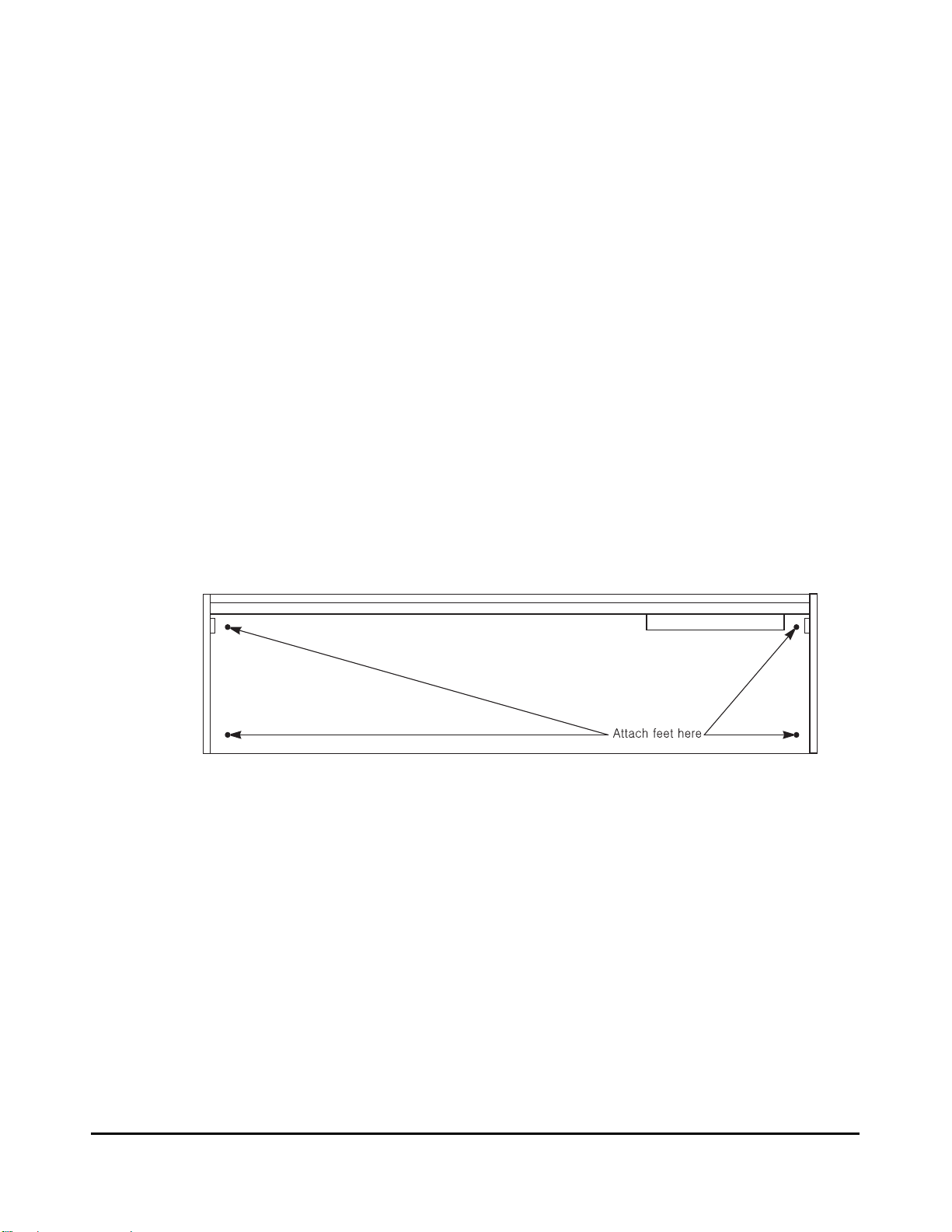
When setting up the PC1 for use it must be placed on a sturdy, level surface where both ends of the
unit are supported. A conventional keyboard stand may be used if it is strong enough to support the
unit’s weight (about 50 pounds for a PC1X, 23 pounds for a PC161). If you are going to be using the
unit on a table now or in the future, apply the four stick-on rubber feet to the bottom. Figure 2-1
shows the recommended locations marked with pairs of small guide holes. Remove the backing
paper from each rubber foot and attach just forward of each set of guide holes. It is possible that
these locations could interfere with some keyboard stand’s supports, so check how the PC1 fits on
your stand before applying the rubber feet.
Figure 2-1 Attaching rubber feet
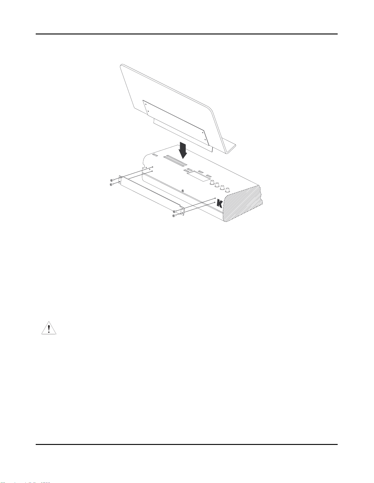
Installing the Music Rack (only for the PC1X model)
You’ll need a Phillips screwdriver to install the optional music rack.
1. Remove the four screws on the rear panel of the PC1, as shown in Figure 2-2.
2. Use the screws to attach the music rack bracket, making sure that the rounded edge of the
bracket is at the top.
3. Slide the music rack in from the top (as shown in the figure).
2-1
Startup
Basic Connections
Basic Connections
Power
The PC1 has an external transformer/power supply with a standard electrical plug on one end, and a
coaxial plug that connects with the PC1. This is a specialized power supply, and is not
interchangeable with other power supplies.
Caution: Use only the power supply that comes with your PC1, or a replacement purchased from an
authorized Kurzweil dealer. Using a different power supply can seriously damage your PC1!
Before connecting the power supply, make sure your PC1 is off
Place the power supply somewhere where it will stay dry and out of the way. We recommend
keeping it on the floor. Never cover the power supply with anything; it needs adequate ventilation
to prevent overheating.
Connect the plug at the other end of the power-supply cable into a standard power outlet. If you
plan to take your PC1 to a location that uses a different voltage level, you’ll need to get an additional
power supply that’s compatible with the local voltage.
Figure 2-2 Installing the music rack
2-2

Audio
The PC1 features balanced left and right analog audio outputs with 1/4-inch jacks. For best results,
use balanced cables to connect to balanced, line-level inputs on your mixer or sound system.
Startup
Basic Connections
It’s important to use shielded, twisted-pair cables. The cables should each have
ring-sleeve) plugs on one end to connect to the PC1. The other end of each cable should have either
1/4
-inch stereo plugs or XLR plugs. Cables of this type provide balanced operation, which greatly
reduces many types of noise. Unbalanced cables or sound-system inputs won’t give you quite the
same audio quality.
For best performance, set the PC1’s Master Volume Slider to its maximum when adjusting mixer or
sound-system levels. Otherwise, if you adjust the PC1’s level by increasing the level of your sound
system, you’ll increase the noise level.
If you’re using a monaural sound system or running the PC1’s audio into a single mixer channel, we
recommend configuring the PC1 for mono output, in which case the PC1 sends the same combined
signal to the left and right sides of the analog outputs. See page 4-21 for information about using
mono audio output mode.
The PC1 has a headphone jack, which carries the same signal as the main outputs (that’s true
whether you’re using stereo or mono output). The headphone jack accepts a standard
plug, and is compatible with nearly all types of headphones. Plugging into the headphone jack does
not mute the other audio outputs.
You can also use the headphone jack as an unbalanced stereo line-level output. Just connect a stereo
cable from the headphone jack to a stereo input on your mixer or sound system. If you have only
unbalanced inputs to your sound system, you’ll get better audio quality using the headphone jack.
1/4
-inch stereo (tip-
1/4
-inch stereo
MIDI
The PC1 both transmits and accepts most standard (and several specialized) MIDI messages. In
other words, it can serve as both a MIDI master and a MIDI slave.
Using the PC1 as a MIDI Master
Connect a MIDI cable from the MIDI Out port of the PC1 to the MIDI In port of the device you want
to control--another MIDI musical instrument, or any device that accepts MIDI, such as a computer
with a MIDI interface or an integrated MIDI In port. This makes the PC1 a MIDI control device, and
you can use it to play other instruments, make recordings using sequencers, or send MIDI System
Exclusive (SysEx) messages for storing programs, setups, and effects settings externally. When the
PC1 is the MIDI master, you can configure it to control only its slaves, or to play its own sounds in
addition to controlling the slaves.
Using the PC1 as a MIDI Slave
Connect a MIDI cable from the MIDI Out port of the instrument or device that you’re using as the
MIDI master to the MIDI In port of the PC1. This makes the PC1 a MIDI slave, enabling you to play
its sounds from any MIDI instrument--keyboard, wind controller, drum pads, whatever--or to
control it via MIDI devices like dedicated sequencers or computers running sequencing applications.
The PC1 can receive 16 independent channels of MIDI information.
2-3

Startup
Basic Connections
MIDI Out/Thru
This jack has two functions: it can be a MIDI Out port, enabling you to send directly to two
different slaves, or it can be a MIDI Thru port, in which case it passes along whatever MIDI
information that the PC1 receives at its MIDI In port (but not the MIDI information that the PC1 itself
generates). This makes it easy to include the PC1 in a chain of multiple MIDI devices, which is a
common configuration when you’re using a computer for sequencing.
There’s a small switch labeled Thru/Out on the PC1’s rear panel (as you face the rear panel, the
switch is to the left of the MIDI In port). Use a small pointed object to set the switch to the position
you want--a ball-point pen works nicely.
Pedals
Plug your switch or continuous pedals into the corresponding jacks on the PC1’s rear panel. We
recommend using the Kurzweil pedals described on page 1-2, but you can use almost any switch or
continuous pedal, as long as it adheres to the following specifications (as most pedals do):
Switch pedals
Continuous pedal 10-kOhm linear-taper potentiometer,
If you use a third-party (non-Kurzweil) switch pedal, make sure it’s connected before you turn on
your PC1. This ensures that the pedal will work properly (it might function backward--off when it’s
down and on when it’s up--if you turn on your PC1 before plugging in the pedal). Similarly, don’t
press any of your switch pedals while powering up, because the PC1 verifies each pedal’s
orientation during power up. If you’re pressing a pedal, you might cause it to work backward.
1/4
-inch tip-ring-sleeve plug (tip goes to pedal 1, ring to pedal 2)
1/4
-inch tip-ring-sleeve plug
The pedals are independently programmable within each zone of every setup. Here are the default
settings for the two pedals you can use with the PC1:
Switch Pedal 1 Controller 64 (Sustain)
Continuous Control Pedal 1 Controller 11 (Expression)
If you use the double piano-style switch pedal, the other pedal works as Switch Pedal 2 - Controller
66 (Sostenuto)
Ribbon
Connect the optional Kurzweil Ribbon Controller into the modular Ribbon jack on the rear panel.
The ribbon controller itself should rest on a flat surface; it fits nicely between the keys and the
buttons and Knobs on the front panel.
The ribbon is a continuous controller. You can program the ribbon controller to send MIDI
Controller messages 1-127, as well as several specialized messages. It generates values of 0-127 for
whatever MIDI Controllers you assign it to send. Just press it, and slide your finger along the ribbon
to change the value of the message it’s sending.
You can configure the ribbon to have one control section that runs its entire length, or to have three
sections of equal length. It sends its highest values when you press it at the end where the cable
connects. When you configure it to have three sections, each section sends its highest values at the
end closest to the cable.
2-4
The ribbon controller comes with an adhesive-backed foam strip and Velcro¨ fastener pads. The
foam strip will hold it in place under most circumstances, but you might find it more convenient
to attach it more securely with the Velcro fasteners (this is recommended when using the ribbon
with a PC161). In that case, we recommend sticking the hook side of each pad to the underside of
the Ribbon and the loop (softer) side to the keyboard. This helps to prevent the hooks in the
Velcro from collecting crud when you don’t have the ribbon attached.
Caution: The modular jack is designed for connection to the Kurzweil Ribbon Controller option only.
Don’t plug any other modular plugs into the Ribbon jack.
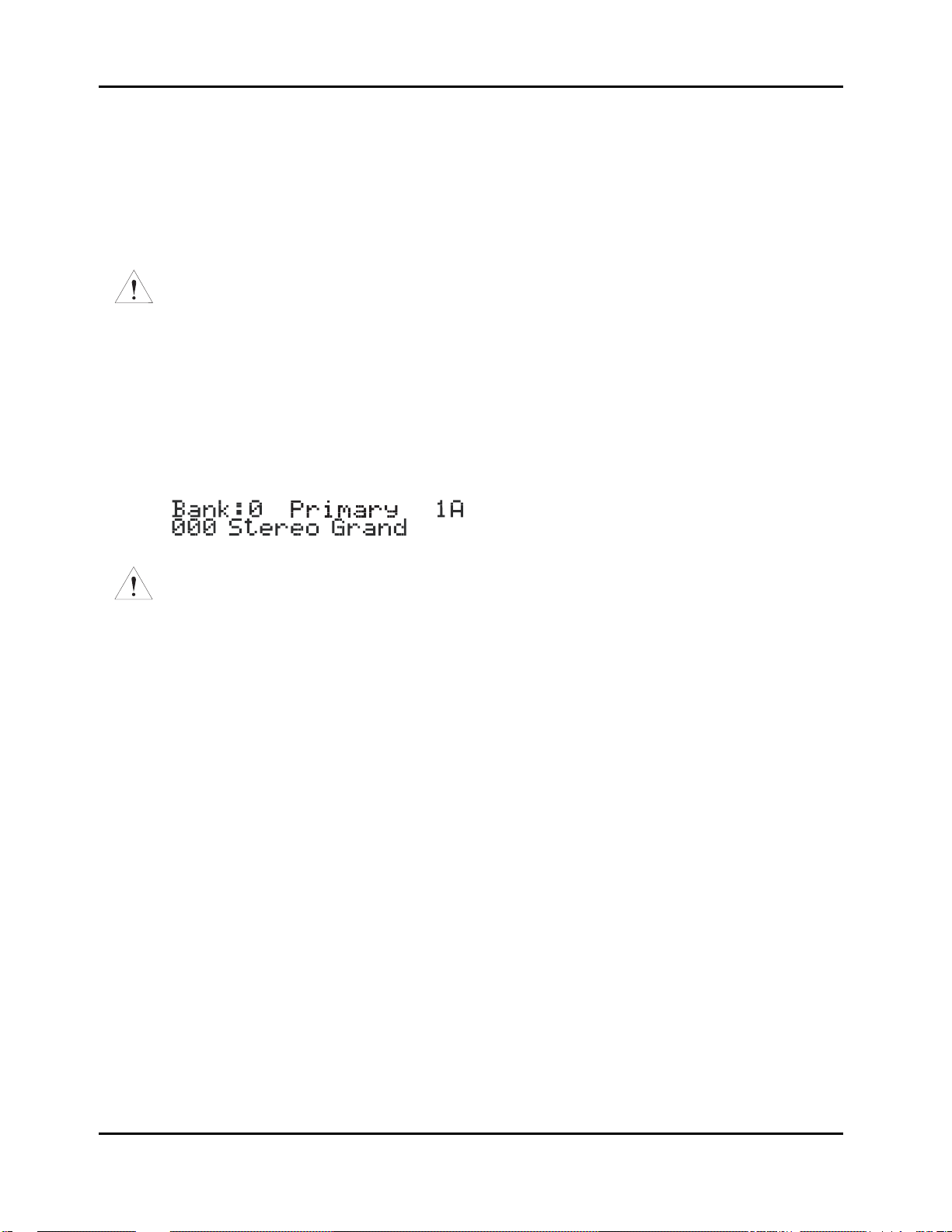
Powering Up
When you’ve made all your connections, turn on the PC1 by pushing the side of the power
switch marked with the vertical line. All of the lights on the front panel flash, and the liquidcrystal display (LCD) shows a series of messages. When the PC1 is ready to play, the display
looks like this:
Startup
Powering Up
Caution: Before playing, we recommend that you slide the volume control nearly to the bottom and
gradually push the control up while playing the keyboard. This way you won’t cause any pain or damage if
there’s too much gain in your sound system.
Display (LCD)
The PC1’s 20x2-character liquid-crystal display tells you what’s going on, whether you’re playing
or editing. Depending on your viewing angle (and possibly the temperature), you may need to
adjust the contrast for better visibility. There’s a small black knob on the rear panel, between the
MIDI ports and the Digital Out jack. Use a screwdriver or your fingertips to turn the knob until
you can read the display easily.
LEDs
Most of the buttons on the PC1’s front panel contain light-emitting diodes that indicate the status
of the features that the buttons control. They should all flash red three times as the PC1 starts up.
Software Upgrades
The PC1 contains a type of reloadable computer memory called Flash ROM, which makes
software upgrades fast and easy. You can learn about new features from your Kurzweil dealer,
or from our website (www.kurzweilmusicsystems.com). See Boot Block on page A-3 for softwareinstallation instructions.
2-5
Startup
Powering Up
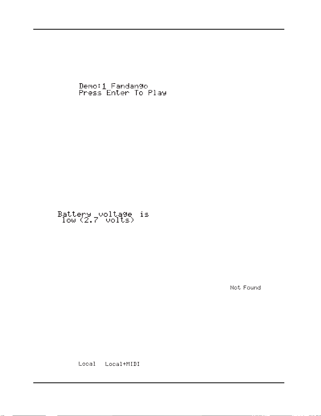
Playing the Demo Sequences
1. Press the Program Select buttons N and P simultaneously to enter Demo mode.(notice
the word Demo on the front panel under these two buttons). The display shows the
following:
2. Press Plus/Minus button or turn the Alpha wheel to select demo song you want to play.
Press Enter to play the demo. During playback, you can stop the demo by pressing
Cancel.
Troubleshooting
No Text in Display
If no messages are displayed when you turn on the power on your PC1 and no LEDs flash, check
the power adapter connections at the AC outlet and the PC1 Adapter In jack. But if the LEDs
flash with no messages in the display, then adjust the LCD contrast knob in the rear panel.
Low Battery
When you turn your PC1 off, a lithium battery protects the memory that the PC1 uses to store
user-defined programs and setups, and other editing changes that you’ve saved. Every time you
turn on your PC1, it automatically checks the battery voltage. If it’s getting low, you’ll see a
message like this before the PC1 finishes starting up:
When you see this message, you should replace your battery immediately, to avoid losing your
data. See page A-1 for instructions.
2-6
No Sound
If no sound comes from the audio or headphones outputs of your PC1 when you play the
keyboard, check the following:
z The Volume Slider might be set too low
z There’s no current program or setup selected (the display shows
z Continuous control pedal 1: check the connection, and check the position of the pedal
z You might be in Setup mode with all zones muted (inactive): press any or all of the four
buttons labeled Zone 1-Zone 4, and the lights in the buttons will turn green
z Local control might be off: press the Global button, then turn the Alpha wheel one click
to the right
z The PC1 might be sending MIDI information only to External MIDI: In Setup mode,
press the Edit button and then press Enter button to enter MIDI Xmit menu, then press
the right cursor button under the display once, then turn the Alpha wheel until you see
or
)

Powering Up
No Sound from Receiving Instrument
If you are trying to control another instrument using MIDI and that instrument doesn’t respond
to your PC1, check the following:
z A working MIDI cable should connect the PC1’s Out or Thru/Out jack to the In jack of
the other instrument
z If you’re using the MIDI Thru/Out port, flip the switch near the MIDI In port to the out
position (a ball-point pen works well for this)
z Continuous control pedal 1: check the connection and pedal position
z The other instrument should be receiving on the same MIDI channel that the PC1 is
using to transmit MIDI information
z All zones that you want to transmit must be active (the lights in the Zone 1-Zone 4
buttons must be green)
z The PC1 might be sending MIDI information only to itself: In Setup mode, press the
Edit button and then press Enter button to enter MIDI Xmit menu, then press the rightarrow button under the display once, then turn the Alpha wheel until you see
Startup
or
2-7


Chapter 3
Performance Features
In This Chapter
Chapter 3 shows you how to get the most out of your PC1 in performance settings. The overview
introduces a few important features and concepts, while the following sections provide more
detail.
z Overview. . . . . . . . . . . . . . . . . . . . . . . . . . . . . . . . . . . . . . . . . . . . . . . . . . . . . . . 3-1
z The Front Panel . . . . . . . . . . . . . . . . . . . . . . . . . . . . . . . . . . . . . . . . . . . . . . . . . 3-4
z Selecting Programs and Setups . . . . . . . . . . . . . . . . . . . . . . . . . . . . . . . . . . . . . 3-10
z EQ . . . . . . . . . . . . . . . . . . . . . . . . . . . . . . . . . . . . . . . . . . . . . . . . . . . . . . . . . . . . 3-12
z Effects . . . . . . . . . . . . . . . . . . . . . . . . . . . . . . . . . . . . . . . . . . . . . . . . . . . . . . . . . 3-12
z Layering and Splitting . . . . . . . . . . . . . . . . . . . . . . . . . . . . . . . . . . . . . . . . . . . . . 3-15
z Muting and Soloing . . . . . . . . . . . . . . . . . . . . . . . . . . . . . . . . . . . . . . . . . . . . . . . 3-18
z General MIDI Features . . . . . . . . . . . . . . . . . . . . . . . . . . . . . . . . . . . . . . . . . . . . 3-19
Overview
Modes
The PC1 has four modes. Each mode provides a different set of functions. You’ll choose modes
depending on what you want to do with the PC1. There are two kinds of modes: performance
mode for playing sounds, and configuration modes for setting up the PC1.
The two main performance modes are Program mode, and Setup mode. You’ll use one of these
modes whenever you’re playing your PC1. Each mode organizes sounds into programs or setups,
which we’ll describe below. Select a performance mode by pressing the corresponding button in
the Modes region at the right side of the front panel.
There are also two configuration modes for making control assignments for each MIDI channel,
and configuring the whole PC1.
Performance Modes
Program Mode
Program mode lets you play one Program at a time. A program consists of one or more sounds
(like piano or strings), and the settings (parameters) that affect those sounds ― for example, the
highest and lowest notes for a particular sound. The PC1 always starts in the program mode,
when you turn it on.
Setup Mode
Setup mode is what makes the PC1 such a powerful MIDI controller. In this mode you can play
one setup at a time. A setup divides the PC1’s keyboard into four zones, each of which can cover
part or all of the keyboard. Each zone can also have its own controller assignment; the Mod
Wheel can do something different in each zone of a setup.
3-1

Performance Features
Overview
Special Modes
While you’re in Program mode, press Main to go to a special setup editor that controls the
internal setup (see Editing the Internal Setup on page 4-21 for more information). The internal
setup defines controller assignments and other characteristics for all the programs in Program
mode. Pressing Main also enables you to create quick layers and splits, as described on page 3-17.
MIDI Receive Mode
Use MIDI Receive mode to configure each MIDI channel independently (this is the mode to use
when you’re driving your PC1 from a multi-channel sequencer). You might think of this mode as
a special performance mode for configuring individual MIDI channels-program assignment,
volume and pan settings, effects routing, and the Wet/Dry mix of the effects.
Global Mode
Use Global mode to make changes that affect the entire PC1-for example, tuning and
transposition, MIDI clock source, program-change protocol, and more.
Objects
Throughout this manual, we’ll occasionally mention objects, which may sound a bit technical, so
we’ll explain. Object is the collective term we use to refer to any chunk of information that the
PC1 stores or processes. Many of these objects are invisible to you, but you’ll be working
regularly with the highest-level object types: programs, setups, and effects. When you’re editing
programs, you might also use System Exclusive (SysEx) messages to store programs, setups or
effects to an external device--or use a single SysEx message to store all the objects you’ve
modified while editing.
The Internal Setup
The two performance modes are quite different from a musician’s viewpoint. The most
noticeable difference is the way the liquid-crystal display (LCD) looks in each mode, as you’ll
learn on page 3-7.
Behind the scenes, however, the performance modes aren’t as different as they seem. In fact, they
have quite a bit in common. For example, consider that familiar controller the Pitch Wheel. Push
it up and you bend notes up; pull it down and you bend notes down. This works in both
performance modes.
The Pitch Wheel does what it does because the PC1 is programmed that way― but you could
program it for other functions if you wanted. In a setup, the Pitch Wheel can do something
different in each zone― and that’s true for all the assignable physical controllers: Mod Wheel,
knobs, pedals, and more.
In a program (Program mode), things are different. From the viewpoint of you the musician,
programs don’t have zones, so each physical controller can do only one thing, but it’s up to you to
decide what each physical controller does. That information gets stored in the internal setup,
which has only one zone, but is otherwise exactly like a setup in Setup mode.
Every program in Program mode uses the internal setup to determine the assignments of the
physical controllers--and many other characteristics.
3-2

EQ
Whichever mode you’re in, the PC1 can apply three-band equalization (EQ) to the programs
you’re playing. Press the Global button to view the current EQ setting. See page 3-12 for more
about changing the EQ settings.
Effects
There are over 150 preset effects, including reverbs, delays, choruses, flangers, phasers, tremolo,
panners, envelope filters, distortions, rotary speakers, compressors, enhancers, waveform
shapers, and multi-effect combinations. There are also 30 preset reverbs. See page 3-12 for more
information about effects.
Physical Controllers
The PC1 provides a wide variety of physical controllers for modifying your sound as you play.
There are two basic types: switch and continuous. Switch controllers generate MIDI messages
with one of two possible values: On (127) and Off (0). Continuous controllers generate MIDI
messages with values from 0 to 127.
The PC1’s onboard switch controllers include four programmable buttons, labeled SW1-
SW4.You can make these buttons momentary (they stay on only when you press and hold them)
or toggle (they alternate between on and off each time you press them). Each of these buttons has
a red LED that lights up when the button is on. These buttons have preset functions in each
performance mode, but you can reprogram them to do all sorts of things.
Performance Features
Overview
There is a jack on the rear panel for a dual switch pedal (the PC1 comes from the factory with one
switch pedal). The terms of ‘dual’ means you can connect up to 2 pedals by using Y cable and
these pedals can also be programmed to be momentary or toggle, and can control a wide range of
performance features.
The onboard continuous controllers include Pitch Wheel, Modulation Wheel, four knobs, and
mono pressure (aftertouch). There are also two jacks on the rear panel for connecting a
continuous controller pedal, and a ribbon controller. These continuous controllers are also fully
programmable, with an extensive choice of options.
3-3
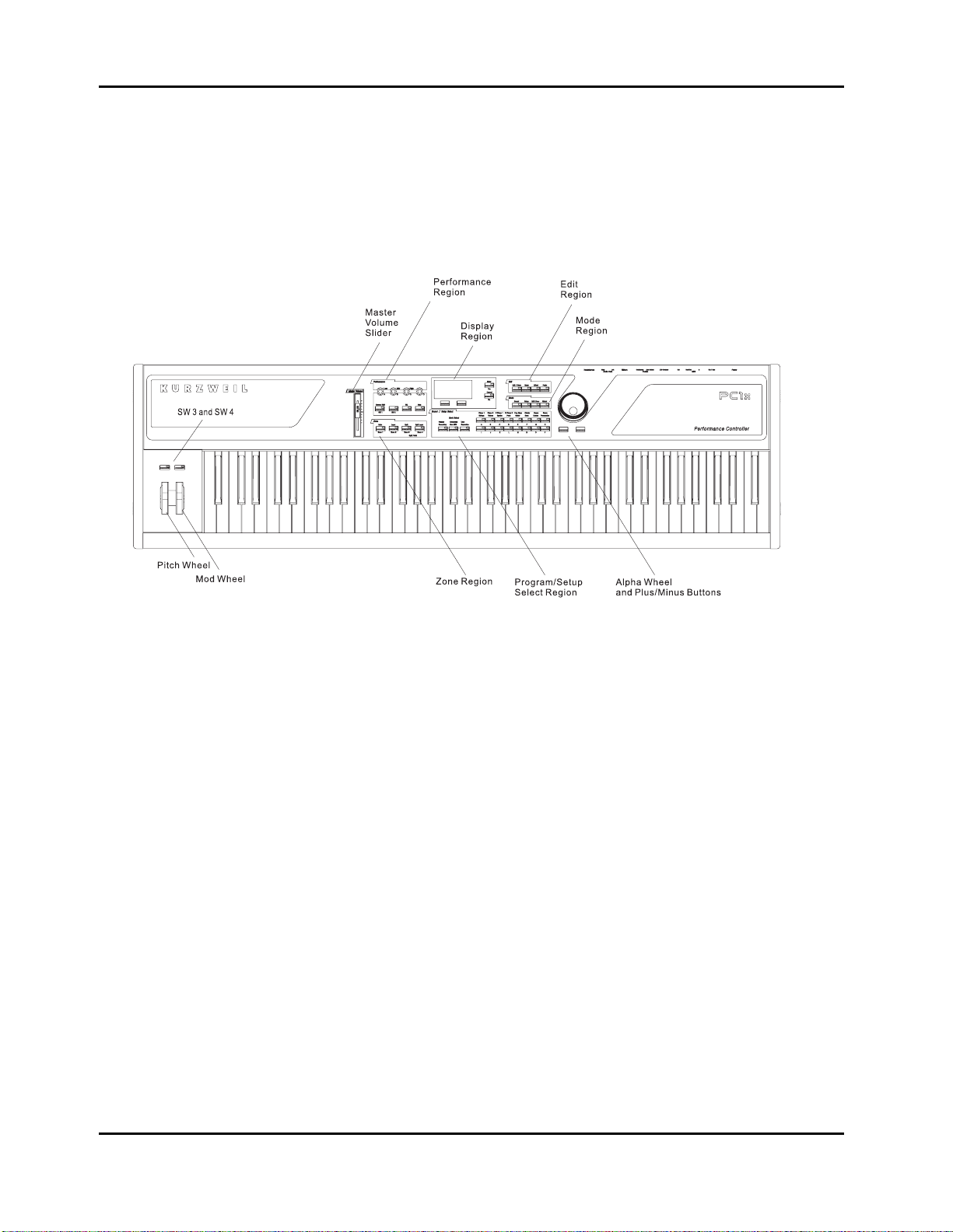
Performance Features
Front Panel
The Front Panel
The buttons, wheels, and knobs on the front panel control your PC1, both during performances,
and when you’re editing. Figure 3-1 identifies everything. In the PC161, Pitch Wheel, Mod Wheel,
SW3 and SW4 are located on left part of the front panel above the keys.
There are six main regions on the PC1’s front panel
The Performance Region
The behavior of most of the buttons and knobs in this region depends on the performance mode.
Knobs A - D
The functions of Knobs A-D depend not only on the performance mode, but also depend on
whether the EQ button is on. When the EQ button is off, the knobs operate as follows:
Program mode
z Knob A controls the wet/dry mix for FX-A, the multi-effect block. You will notice a
change in the effect level if the Effect button’s LED is Green or Amber.
z Knob B controls the wet/dry mix for FX-B, the reverb block. You will notice a change in
the reverb level if the Effect button’s LED is Red or Amber.
z Knob C is usually a timbre control, although it can vary from program to program.
z Knob D has different functions depending on the current program.
Remember that controller assignments in Program mode are defined by the internal setup, which
you can edit in AutoSplit mode (which is a subset of the Setup Editor)—while in Program mode,
press Main; hold Global and move a knob to select its Ctrl Num parameter; change its value;
Figure 3-1 The PC1
3-4

Performance Features
Front Panel
press Store; press the Program button at the Save prompt. See page 3-17
Setup mode
Knobs A–D are also programmable in Setup mode, and like the programmable buttons, they can
do different things in each zone of each setup.
Assignable Switch Button
Program mode
Button SW1 (also labeled Octave Shift) is a convenient way to “transpose” the entire PC1 down
one octave in Program mode. Press SW1 once to activate transposition, and the LED will light.
This causes a “note shift” that for most programs lowers the pitch an octave. What’s actually
happening is that the programs get shifted so that each key plays a different MIDI note number
(for example, C4 normally plays Note Number 60, but with octave shift on, it plays Note Number
48). We mention this because in most programs, it seems that you’re transposing down an octave.
For non-pitched programs like drums and percussion, however, each sound gets moved an
octave upward (so if you play C4 to play a snare with octave shift off, you’ll play C5 to get the
same snare when octave shift is on). Press SW1 again to remove the shift
If you’ve used the AutoSplit feature to make quick layers and splits, the octave shift transposed
the layers in the lower part of the keyboard (corresponding to the Zone 3 and Zone 4 buttons) up
one octave, and transposes the layers in the upper part of the keyboard (corresponding to the
Zone 1 and Zone 2 buttons) down one octave. This keeps the low notes from being too low, and
the high notes from being too high.
Button SW2 activates or deactivates the chorus and vibrato effects built into many of the organ
voices in Program mode. Button SW2 also has uses in some of the non-organ programs. Check
out Program 96 and listen for the changes in the sound as you switch the button on and off.
Although Buttons SW3 and SW4 aren’t in the same region as SW1 and SW2, they work in a
similar manner (they’re located near the Pitch Wheel and Mod Wheel). By default, SW3 activates
the arpeggiator when it’s on, and deactivates it when it’s off. The default setting for SW4 is to
send MIDI Controller 29 with a value of 127 when it’s on; it sends MIDI Controller 29 with a
value of 0 when it’s off.
Note: The functions of SW1~SW4 in Program mode are defined by the internal setup, but they’re
programmable. If you want them to do something else, you can edit the internal setup and change the
buttons’ assignments. Keep in mind, however, that this will affect all programs in Program mode.
3-5

Performance Features
Front Panel
The following table is the summary of controller assignment in Program mode (Internal Setup)
Controller Assignment MIDI Control Num
Knob A FX-A Depth MIDI 91
Knob B FX-B Depth MIDI 93
Knob C Assignable (Timbre) MIDI 06
Knob D Assignable (Timbre) MIDI 13
SW1 Octave Shift No MIDI Message
SW2 Assignable (Timbre) MIDI 09
SW3 Arp On/Off No MIDI Message
SW4 Assignable (Timbre) MIDI 29
MW Assignable (Vibrato) MIDI 01
Mpress Aftertouch MIDI 33
Ribbon Pitchbend MIDI 21/53
CCPed Expression MIDI 11
Setup mode
Buttons SW1-SW4 are programmable in Setup mode. They can have different functions for each
zone in every setup. In other words, you can change what one of these buttons does in Zone 1 of
a setup, for example, and it won’t change what that button does in the other zones of that setup
(or in any other setup).
EQ
The PC1 has its own three-band global equalization (EQ). See EQ on page 3-12 for details.
Solo
In either Program mode or Setup mode, pressing this button turns on the solo feature (if you’re
in Program mode, the PC1 switches to AutoSplit mode—a special performance configuration of
Setup mode.). When the Solo feature is on, (that is, when its LED is lit), pressing one of the Zone
buttons solos that zone, so you hear that zone only. See page 3-18 for more about muting and
soloing program.
The Zone Region
Main
In Program mode, this button takes you to AutoSplit mode—a special performance and editing
configuration of Setup mode. In this case, the Zone 2–Zone 4 buttons add splits or layers, as
indicated (See page 3-15 for more information about layering and splitting). In Setup mode, this
button selects Zone 1 for viewing or editing. Press it again to mute/unmute the zone.
3-6
Layer
In Program mode, this button switches the PC1 into AutoSplit mode, and adds a layer.
In Setup mode, this button selects Zone 2 for viewing or editing.
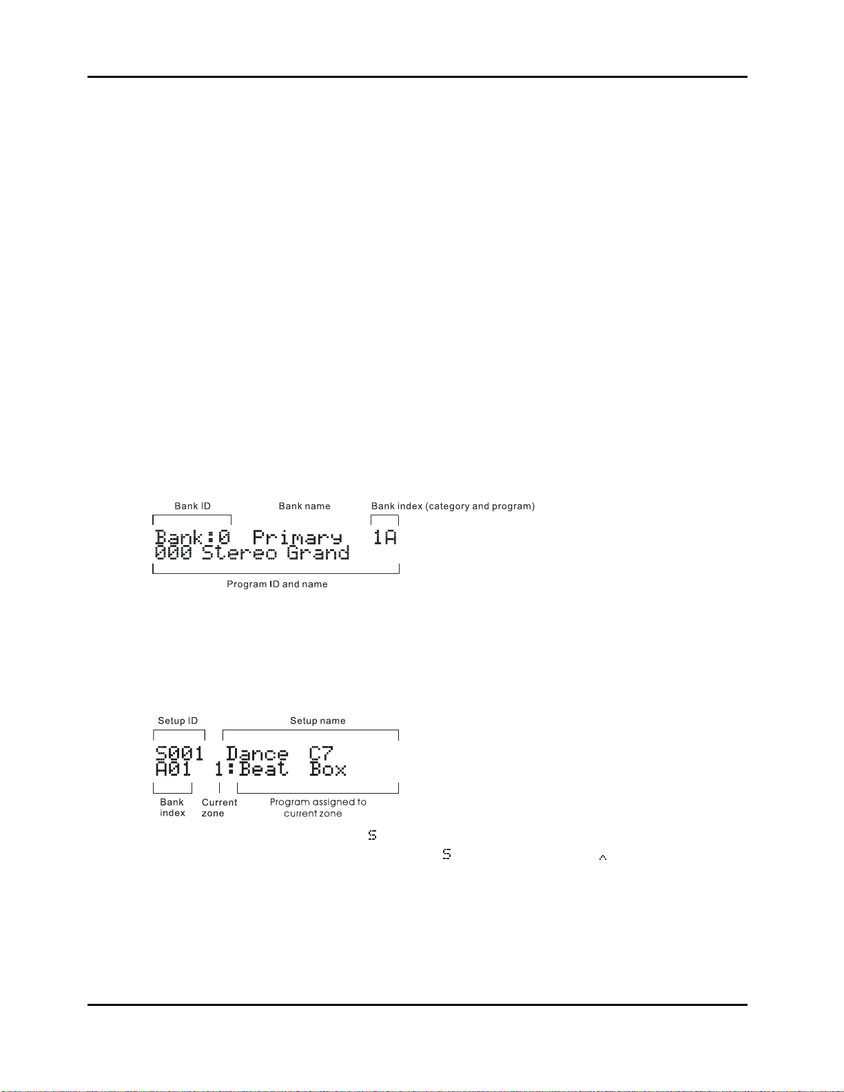
Split
In Program mode, this button switches the PC1 into AutoSplit mode, and adds a new Program
below a preset split point.
In Setup mode, this button selects Zone 3 for viewing or editing.
Split Layer
In Program mode, this button switches the PC1R into AutoSplit mode, and adds a layer to the
Program below the split point.
In Setup mode, this button selects Zone 4 for viewing or editing.
In any performance mode, pressing Split and Split Layer together is an editing shortcut that
displays the AutoSplit Key parameter. You can then use the Alpha Wheel to change the
AutoSplit key (or hold down the Enter button and play a note on the keyboards). Press Cancel to
return to your performance mode.
The Display Region (LCD)
The display looks quite different in each mode, so we’ll show you examples of each.
Program Mode
Performance Features
Front Panel
When you turn on your PC1, the display should look like this:
This is Program mode, where the PC1 always starts when you turn it on (to get to Program mode
from another mode, press the Program button). The top line gives you information about the
bank, while the bottom line shows the ID and name of the current program.
Setup Mode
Press the Setup button to enter Setup mode, and the display looks like this:
The setup ID usually begins with
that have the AutoSplit feature turned on, the
index is a letter followed by a numeral, which is the opposite of the way the bank index looks in
Program mode.
to indicate that you’re playing a setup-although in setups
is replaced by a caret ( ). Notice that the bank
3-7

Performance Features
Front Panel
The Edit Region
There are four buttons in the Edit region. This region also includes the Panic button. For
programming your PC1, you can access Edit mode with the buttons in this region.
Edit
Press the Edit button to enter the edit mode corresponding to your current performance mode.
This is where you make changes to the parameters that define programs, setups, and effects. See
Chapter 4 for specifics about programming your PC1.
Once you’re in an edit mode, this button becomes the Store button. Press Edit to bring up a Save
dialog, then either press Yes to save the current object, or use the cursor buttons to select another
related function. See Naming and Storing on page 4-2 for more information.
Menu
When you’re editing programs or setups, press Menu to select the first menu of programming
parameters in the current edit mode. Use the cursor buttons to view the available menus, then
press Enter to view the parameters in the current menu. When you’re finished viewing
parameters, press Menu again to return to the list of menus.
Effect
The Effect button takes you to FX parameters in the edit mode that corresponds to your current
performance mode. From FX parameters, you can assign a different effect to the current program
or setup, and you can edit the current effect. See 3-12 for more information about editing effects.
Panic
This button sends All Notes Off messages and Reset All Controllers messages on all MIDI
channels-both to the PC1’s sound engine and its MIDI Out port
The Mode Region
The four buttons in the Mode Region take you to various performance and editing modes.
Program
Press this button to get to Program Mode from any performance or editing mode. Program is the
mode to use for playing Programs.
Setup
Press this button to get to Setup mode from any performance or editing mode. Use Setup mode
when you want to play programs on up to four different MIDI channels.
MIDI Receive
This button takes you to MIDI Receive mode, where you can configure how the PC1 responds to
incoming MIDI information. The first time you enter MIDI Receive mode after powering up, the
display shows Channel 1, because the PC1 resets the MIDI Receive channel each time you shut
down. Until you shut down again, the PC1 tracks which channel you’re viewing even after
you’ve left MIDI Receive mode, so the next time you enter MIDI Receive mode, the display
shows the channel you were most recently viewing.
3-8
 Loading...