

Page 1

KSP8 I/O Option
Installation and Usage Guide
This document explains how to install an I/O Option Board into a Kurzweil KSP8. The following I/O Option
boards are available for the KSP8:
•
Analog I/O Option Board
•
ADAT–TDIF I/O Option Board
•
AES I/O Option Board
•
mLAN (Firewire) I/O Option Board
These options are user-installable; no special expertise or special tools are required. Furthermore, the installation
procedure is the same for all the option boards. Usage instructions for the individual options are provided at the
end of this document.
IMPORTANT: The I/O option boards are not hot-swappable. You must turn off the KSP8 before you add or
remove an I/O option board.
Before Beginning the Installation
You should back up any objects (presets, chains, or studios) that you have created. You can either save the objects
to a SmartMedia card or dump the objects via MIDI using a SysEx dump. Refer to Chapter 10 of the KSP8 User’s
Guide for information on these procedures.
Tools Required For Installation
•
#2 Phillips screwdriver
You will need access to the back panel of the KSP8.
Installation
1. Turn the unit off, then unplug all cables from the KSP8.
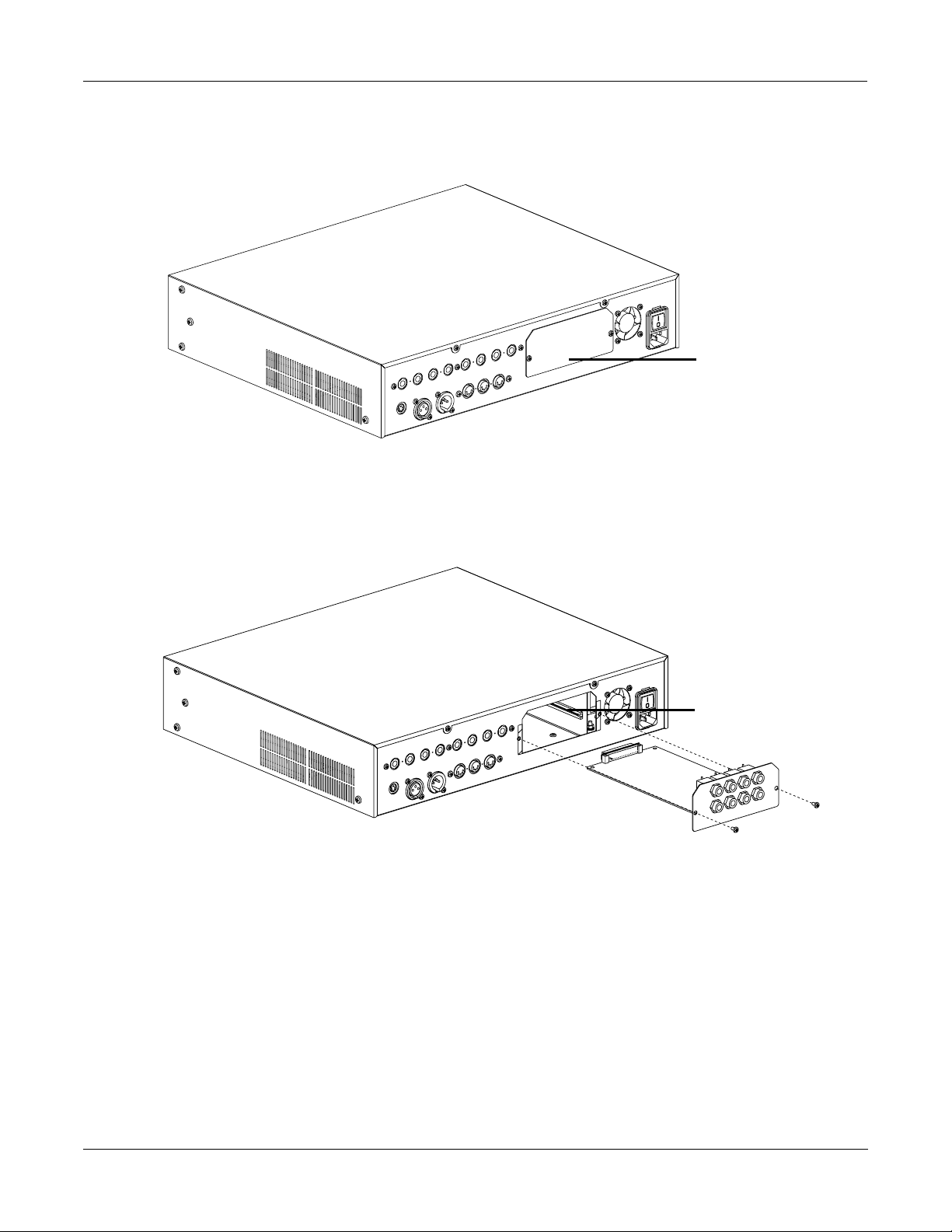
2. Using a #2 Phillips screwdriver, remove the two screws attaching the option slot cover plate to the
back panel of the KSP8. Set the screws aside so that you can use them to attach the option board.
The option slot cover plate is shown in Figure 1.
Young Chang Co., Ltd. 2003. Subject to change without notice. All trademarks are the properties of their respective owners.
Part No. 910360, Rev. E
Page 2
Installation
option slot
cover plate
Figure 1. Rear view of KSP8, showing location of option slot cover plate.
3. Slide the I/O option board into the option slot as shown in Figure 2. Make sure the side edges of
the board slide into the plastic rails inside the option slot.
plastic rail
Figure 2. Inserting option board into KSP8 (Analog I/O Option pictured).
4. Slide the board all the way into the KSP8, making sure that it becomes securely seated in the
connector at the back of the opening.
2
5. Attach the board to the KSP8 using the screws that originally held the option slot cover plate in
place. Figure 2 shows the location for these screws.
6. To confirm that the installation has been successful, turn the KSP8 on, then refer to the option’s
usage section below.
Page 3

Using the KSP8 Analog I/O Option (KANA4)
Using the KSP8 Analog I/O Option (KANA4)
The Analog I/O Option adds four inputs and four outputs to your KSP8. The connectors are the same balanced
1/4" phone jacks that are used for the analog I/O on the stock KSP8, and their function is exactly the same. The
only difference you will see will be on the Config INSEL and INLVL pages:
•
The INSEL page will offer parameters Analog1 – Analog8 for each input.
•
The INLVL page will feature a second column for Inputs 5 – 8.
To confirm that the installation of the Analog I/O Option has been successful:
1. Press the config button.
2. Press the INLVL soft button. Two columns of inputs should be displayed, as shown below.
If only inputs 1 through 4 are displayed, the KSP8 is not recognizing the option. In this case, you
should confirm that the board is seated properly: turn off the KSP8, remove the board, then
reinsert it, making sure that it slides into both plastic rails and becomes seated in the connector at
the back of the opening.
Studio:INLVL|||||||||||I/O|Config=Studio
||||||||||||||||||||||||||||||||||||||||
In|1: 0.0dB|||||||||||||In|5:0.0dB|||||||
In|2:0.0dB|||||||||||||In|6:0.0dB|||||||
In|3:0.0dB|||||||||||||In|7:0.0dB|||||||
In|4:0.0dB|||||||||||||In|8:0.0dB|||||||
||||||||||||||||||||||||||||||||||||||||
INSEL|| INLVL| INGRP|| BUSCFG| OUTSEL| OUTLVL
3
Page 4

Using the KSP8 ADAT–TDIF I/O Option (KADT8)
Using the KSP8 ADAT–TDIF I/O Option (KADT8)
The ADAT–TDIF I/O Option adds the following to your KSP8:
•
eight digital inputs and outputs for the ADAT Optical Interface.
•
eight digital inputs and outputs for devices that use the TDIF format.
Once you’ve installed the option as described in the first part of this document, check to make sure that your
KSP8’s software is revision 1.5 or higher. The most current KSP8 software is provided on a SmartMedia card
included with this option. You can update your software (if necessary) with the KSP8 Boot Loader, as described in
the KSP8 User’s Guide .
To confirm that the installation of the ADAT–TDIF I/O Option has been successful:
1. Press the config button.
2. Press the INSEL soft button. Turn the alpha wheel to display the available input selections for the
selected input. Among these should be the ADAT and TDIF inputs.
If the ADAT–TDIF inputs do not appear when you scroll through the input selections, the KSP8 is
not recognizing the option. In this case, you should confirm that the board is seated properly: turn
off the KSP8, remove the board, then reinsert it, making sure that it slides into both plastic rails
and becomes seated in the connector at the back of the opening.
You will now be able to interface with both ADAT and TDIF type devices. You can even set some of your inputs
(INSEL page) to hook up to an ADAT-type device while you set others for TDIF. The only limitation is that inputs
of one type cannot overlap those of the other type; for example, if you’ve selected ADAT 1 for an input then TDIF 1
will be unavailable (although TDIF 2–8 may still be available for your use). All 16 outputs, however, are always
live.
While the INSEL page offers parameters ADAT 1–ADAT 8 and TDIF 1–TDIF 8 when an ADAT–TDIF option is
detected, nothing changes on the INLVL page, since that page is only concerned with analog inputs.
Studio Configuration Files
For your convenience, two configuration files, ADA T nn .KSP and TDIF nn .KSP are provided on the included
SmartMedia card. Each file contains a subset of the base KSP8 studios with the appropriate input selections made,
as well as a Master table that sets the Clock Source parameter as necessary. To load these files, first insert the
SmartMedia card (gold side down) into the KSP8, then press the MASTER soft button, followed by CARD , then
Load . You will now be able to select and load the configuration file that you would like. (Note that while the KSP8
will prompt you to save these objects into the 800s bank, you can place them into any bank of your choosing. See
the KSP8 User’s Guide for more information on loading and arranging objects.)
The files contain the following objects:
4
800 4SterIn>4SterFX
801 4MonoIn>4SterFX
802 8MonoIn>8MonoFX
803 Morph This
804 6 MonoIn>5.1 FX+
805 8 MonoIn>5.1 FX
Page 5

806 MnIn>5.1 AutoPan
807 3 SterIn>5.1 FX+
808 4 SterIn>5.1 FX
809 5.1 In>5.1 FX +
810 Default 5.1+Ster
811 Default 8 Mono
812 Default 4 Stereo
Master Table
Master Page Configuration Parameters
Using the KSP8 ADAT–TDIF I/O Option (KADT8)
Some ADAT or TDIF configurations require that you set some of the parameters on the KSP8 Master page. Mostly
these have to do with clock selection and TDIF types. Refer to Chapter 10 of the KSP8 User’s Guide for information
on the KSP8 Master page.
The connection diagrams that follow this section will help to clarify some of this information.
ClockSource
You will have to set the ClockSource parameter to indicate which device is the master. The choices are:
•
44.1 KHz Internal
•
48 KHz Internal
•
AES/EBU
•
ADAT
•
TDIF
•
Word Clock
TDIF T ype
TDIF connection only. You will only need to set the TDIF Type parameter for TDIF configurations when Clock
Source is Word Clock.
Choose “DA-88” for connection to a TASCAM DA-88. Choose “Other” for all other products (including TASCAM
products other than the DA-88).
TDIF Len
TDIF connection only. Indicate the word length for your TDIF input data. This should match the word length used
by the sending TDIF device. (The word length for KSP8 output is set with the DigWordLen option, also on the
Master page.)
5
Page 6
Using the KSP8 ADAT–TDIF I/O Option (KADT8)
O
Configuration and Connection Examples
The examples below show the most effective way to use your KSP8 in a variety of situations.
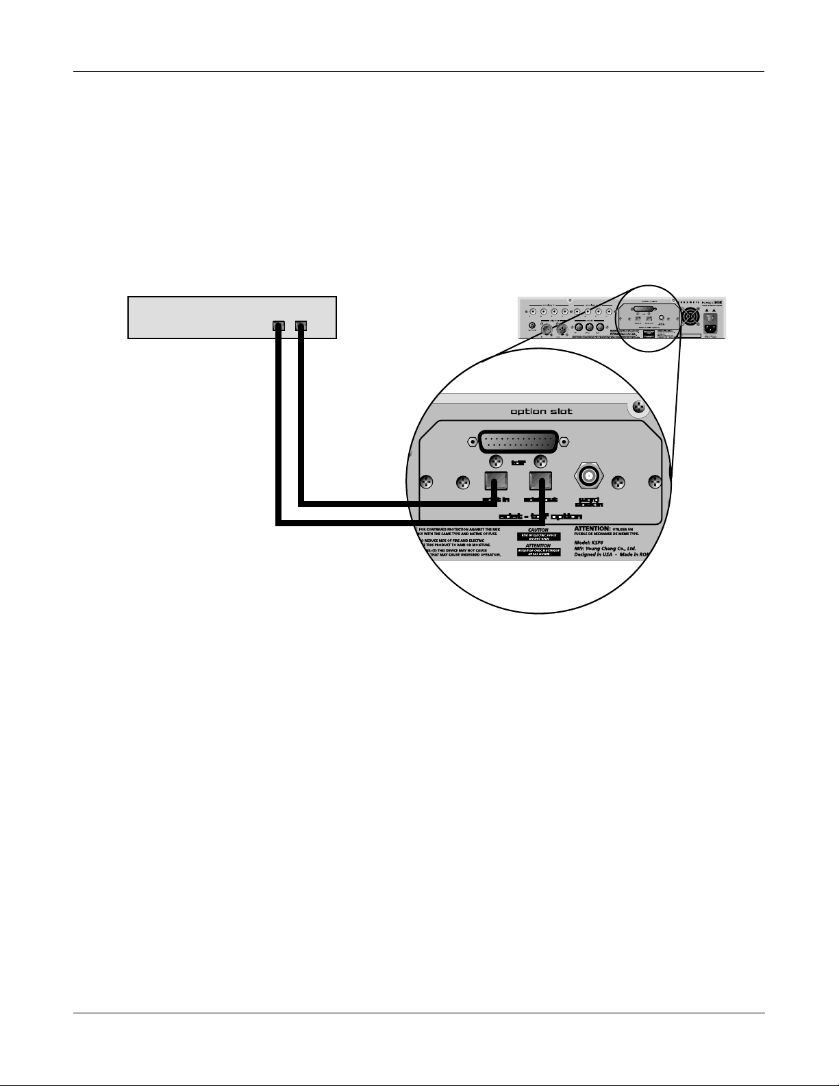
ADAT Optical Interface
KSP8Device with ADAT
Optical Interface
In Out
For this configuration, you should make the following selections on the KSP8 Master and INSEL pages.
Master||||||||||||||||||||||Memory:751K|
StudioChanl: 9||||||||||SysEx|ID:|0
I/O|Config|:Studio|||||TDIF|Type:Other
ClockSource:ADAT|||||||TDIF|Len:16|Bit|
DigWordLen|:16|Bit|||||||||||||||||||||
DitherType|:Minimum||||||||||||||||||||
DigFor
mat||:OAES/EBU|O||||||O||||||||O||||||
<back|O||CARD||OBJECT||UTIL|Standby|Reset
Studio:INSEL|||||||||||I/O|Config=Studio
||||||||||||||||||||||||||||||||||||||||
In|1:|ADAT|1|||||||||In|5:ADAT|5||||||||
In|2:|ADAT|2|||||||||In|6:ADAT|6||||||||
In|3:|ADAT|3|||||||||In|7:ADAT|7||||||||
In|4:|ADAT|4|||||||||In|8:ADAT|8||||||||
||||||||||||||||||||||||||||||||||||||||
INSEL||INLVL|INGRP||BUSCFG|OUTSEL|OUTLVL
6
Page 7

DA-88 TDIF Connection
Using the KSP8 ADAT–TDIF I/O Option (KADT8)
KSP8DA-88
TDIF I/O
For this configuration, you should make the following selections on the KSP8 Master and INSEL pages.
Master||||||||||||||||||||||Memory:751K|
StudioChanl:9||||||||||SysEx|ID:|0
I/O|Config|:Studio|||||TDIF|Type:DA88||
ClockSource:TDIF|||||||TDIF|Len:16|Bit|
DigWordLen|:16|Bit|||||||||||||||||||||
DitherType|:Minimum||||||||||||||||||||
DigFormat||:AES/EBU|||||||||||||||||||||
<back|||CARD||OBJECT||UTIL|Standby|Reset
Studio:INSEL|||||||||||I/O|Config=Studio
||||||||||||||||||||||||||||||||||||||||
In|1:|TDIF|1|||||||||In|5:TDIF|5||||||||
In|2:|TDIF|2|||||||||In|6:TDIF|6||||||||
In|3:|TDIF|3|||||||||In|7:TDIF|7||||||||
In|4:|TDIF|4|||||||||In|8:TDIF|8||||||||
||||||||||||||||||||||||||||||||||||||||
INSEL||INLVL|INGRP||BUSCFG|OUTSEL|OUTLVL
7
Page 8

Using the KSP8 ADAT–TDIF I/O Option (KADT8)
MOTU 2408 TDIF Connection
TDIF
In Out
ADAT
KSP8MOTU 2408
NOTE: Clock Source must be ADAT
For this configuration, you should make the following selections on the KSP8 Master and INSEL pages.
Master||||||||||||||||||||||Memory:751K|
StudioChanl:9||||||||||SysEx|ID:|0
I/O|Config|:Studio|||||TDIF|Type:DA88||
ClockSource:ADAT|||||||TDIF|Len:16|Bit|
DigWordLen|:16|Bit|||||||||||||||||||||
DitherType|:Minimum||||||||||||||||||||
DigFormat||:AES/EBU|||||||||||||||||||||
<back|||CARD||OBJECT||UTIL|Standby|Reset
Studio:INSEL|||||||||||I/O|Config=Studio
||||||||||||||||||||||||||||||||||||||||
In|1:|TDIF|1|||||||||In|5:TDIF|5||||||||
In|2:|TDIF|2|||||||||In|6:TDIF|6||||||||
In|3:|TDIF|3|||||||||In|7:TDIF|7||||||||
In|4:|TDIF|4|||||||||In|8:TDIF|8||||||||
||||||||||||||||||||||||||||||||||||||||
INSEL||INLVL|INGRP||BUSCFG|OUTSEL|OUTLVL
8
Page 9

Using the KSP8 ADAT–TDIF I/O Option (KADT8)
MOTU 2408 TDIF Connection with External Word Clock
TDIF
Word Clock In
Word Clock Outs
KSP8MOTU 2408
External Word Clock Generator
For this configuration, you should make the following selections on the KSP8 Master and INSEL pages.
Master||||||||||||||||||||||Memory:751K|
StudioChanl:9||||||||||SysEx|ID:|0
I/O|Config|:Studio|||||TDIF|Type:Other|
ClockSource:Word|Clock|TDIF|Len:16|Bit|
DigWordLen|:16|Bit|||||||||||||||||||||
DitherType|:Minimum||||||||||||||||||||
DigFormat||:AES/EBU|||||||||||||||||||||
<back|||CARD||OBJECT||UTIL|Standby|Reset
Studio:INSEL|||||||||||I/O|Config=Studio
||||||||||||||||||||||||||||||||||||||||
In|1:|TDIF|1|||||||||In|5:TDIF|5||||||||
In|2:|TDIF|2|||||||||In|6:TDIF|6||||||||
In|3:|TDIF|3|||||||||In|7:TDIF|7||||||||
In|4:|TDIF|4|||||||||In|8:TDIF|8||||||||
||||||||||||||||||||||||||||||||||||||||
INSEL||INLVL|INGRP||BUSCFG|OUTSEL|OUTLVL
9
Page 10

Using the KSP8 ADAT–TDIF I/O Option (KADT8)
Yamaha Digital Mixer with TDIF Card
Yamaha digital mixer with TDIF card
TDIF I/O
KSP8
For this configuration, you should make the following selections on the KSP8 Master and INSEL pages.
Master||||||||||||||||||||||Memory:751K|
StudioChanl:9||||||||||SysEx|ID:|0
I/O|Config|:Studio|||||TDIF|Type:Other|
ClockSource:TDIF|||||||TDIF|Len:16|Bit|
DigWordLen|:16|Bit|||||||||||||||||||||
DitherType|:Minimum||||||||||||||||||||
DigFormat||:AES/EBU|||||||||||||||||||||
<back|||CARD||OBJECT||UTIL|Standby|Reset
Studio:INSEL|||||||||||I/O|Config=Studio
||||||||||||||||||||||||||||||||||||||||
In|1:|TDIF|1|||||||||In|5:TDIF|5||||||||
In|2:|TDIF|2|||||||||In|6:TDIF|6||||||||
In|3:|TDIF|3|||||||||In|7:TDIF|7||||||||
In|4:|TDIF|4|||||||||In|8:TDIF|8||||||||
||||||||||||||||||||||||||||||||||||||||
INSEL||INLVL|INGRP||BUSCFG|OUTSEL|OUTLVL
10
Page 11

Using the KSP8 AES I/O Option (KAES8)
Using the KSP8 AES I/O Option (KAES8)
The AES I/O Option adds four stereo input/output pairs to your KSP8. This option requires that the software
revision level on your KSP8 be 1.7 or higher. The most current KSP8 software is provided on a SmartMedia card
included with this option. You can update your software (if necessary) with the KSP8 Boot Loader, as described in
the KSP8 User’s Guide.
To confirm that the installation of the AES I/O Option has been successful:
1. Press the config button.
2. Press the INSEL soft button. Turn the alpha wheel to display the available input selections. The
“Option AES” inputs, such as shown below, should be available for all the inputs.
Studio:INSEL|||||||||||I/O|Config=Studio
||||||||||||||||||||||||||||||||||||||||
In|1:Option|AES|1L|||In|5:Option|AES|3L|
In|2:Option|AES|1R|||In|6:Option|AES|3R|
In|3:Option|AES|2L|||In|7:Option|AES|4L|
In|4:Option|AES|2R|||In|8:Option|AES|4R|
||||||||||||||||||||||||||||||||||||||||
INSEL||INLVL|INGRP||BUSCFG|OUTSEL|OUTLVL
If the Option AES inputs do not appear when you scroll through the input selections, the KSP8 is not
recognizing the option. In this case, you should confirm that the board is seated properly: turn off the
KSP8, remove the board, then reinsert it, making sure that it slides into both plastic rails and becomes
seated in the connector at the back of the opening.
As you may observe while scrolling through the input selections on the INSEL page, the Base AES pair is still
available (in addition to the Option AES inputs). We recommend, however, that you use only the Option AES
inputs and outputs when you have the option installed.
Important: For each desired AES output pair, you must have a valid AES input on the corresponding pair. For
example, to use AES out 3-4, you must have an AES input connected to 3-4 (regardless of clock source).
ClockSource
The ClockSource parameter on the Master page lets you select one of the following as master clock:
• 44.1 KHz Internal
• 48 KHz Internal
• Base AES
• Option AES*
• Word Clock
*When Option AES is the clock source setting, you must connect AES input 1-2, since the AES clock is derived from
AES input 1-2.
11
Page 12

Using the KSP8 AES I/O Option (KAES8)
Studio Configuration Files
For your convenience, a configuration file named AESnn.KSP is provided on the included SmartMedia card. This
file contains a subset of the base KSP8 studios with the appropriate input selections made, as well as a Master table
that sets the Clock Source parameter to Option AES. To load the file, first insert the SmartMedia card (gold side
down) into the KSP8, then press the MASTER soft button, followed by CARD, then Load. You will now be able to
load the configuration file. (Note that while the KSP8 will prompt you to save these objects into the 100s bank, you
can place them into any bank of your choosing. See the KSP8 User’s Guide for more information on loading and
arranging objects.)
The files contain the following objects:
100 4SterIn>4SterFX
101 4MonoIn>4SterFX
102 8MonoIn>8MonoFX
103 Morph This
104 6 MonoIn>5.1 FX+
105 8 MonoIn>5.1 FX
106 MnIn>5.1 AutoPan
107 3 SterIn>5.1 FX+
108 4 SterIn>5.1 FX
109 5.1 In>5.1 FX +
110 Default 5.1+Ster
111 Default 8 Mono
112 Default 4 Stereo
Master Table
12
Page 13

Using the KSP8 AES I/O Option (KAES8)
Pinout for AES/EBU Connector
The KSP8 AES Option uses a single DB-25 connector to provide four stereo input and output channels. While
different manufacturers have used different standards in the pin assignments of these connectors for AES/EBU,
the KSP8 employs the pinout used by the TASCAM DB-25 balanced connector. This is shown below:
13
25
Notes:
• View is from back panel of KSP8.
• G = Ground; C = Cold (–); H = Hot (+).
• Pin 13 is not used.
Channel Pair Hot + Cold - Ground
Input 1-2 24 12 25
Input 3-4 10 23 11
Input 5-6 21 9 22
Input 7-8 7 20 8
Output 1-2 18 6 19
Output 3-4 4 17 5
Output 5-6 15 3 16
Output 7-8 1 14 2
24
HG
In
(to KSP8)
101112
22
23
Out
(from KSP8)
8
9
7
20
21
5
6
4
1819
17
2
3
5–61–25–61–27–83–47–83–4
1
141516
HGCHGCHGCHGC
CHGCHGCHGC
Table 1. Pinouts for KSP8 AES Connector.
13
Page 14

Using the KSP8 AES I/O Option (KAES8)
Cable Requirements
Cables for connecting the KSP8 AES Option should be constructed from shielded twisted-pair wiring with a
nominal impedance of 110 ohms. The ground pins on each end of the cable connect to shields. The most common
cable types are described below:
• DB-25 to 8 XLRs
(e.g., Hosa DMP-235 or Redco S8 PLM-10R) This cable will connect four female XLR connectors to the
KSP8 inputs, and four male XLR connectors to the KSP8 outputs, as shown below:
12
3
2
1
3
DB-25 (Male)
XLR (Male)
XLR (Female)
Hot
Cold
Ground
Hot
Ground
Cold
This cable allows attachment to any device that uses XLR AES connections. The DB-25 uses the pinout
shown in Table 1.
When using this cable with Option AES as clock, you must use input channels 1 and 2.
14
Page 15

Using the KSP8 AES I/O Option (KAES8)
• DB-25 to DB-25 AES cable (male-to-male) with KSP8-type pinouts
This cable will have pinouts as shown in Table 1 for connection to any device that uses the same AES
pinout as the KSP8, for example, the Panasonic DA7 digital mixer. Since the pinout is the same on each
end of this cable, it must be wired in a crossover configuration, as shown in Table 2.
Pin on Connector 1 Pin on Connector 2
24 In 1-2 + connects to Out 1-2 + 18
12 In 1-2 – connects to Out 1-2 – 6
25 In 1-2 Gnd connects to Out 1-2 Gnd 19
10 In 3-4 + connects to Out 3-4 + 4
23 In 3-4 – connects to Out 3-4 – 17
11 In 3-4 Gnd connects to Out 3-4 Gnd 5
21 In 5-6 + connects to Out 5-6 + 15
9 In 5-6 – connects to Out 5-6 – 3
22 In 5-6 Gnd connects to Out 5-6 Gnd 16
7 In 7-8 + connects to Out 7-8 + 1
20 In 7-8 – connects to Out 7-8 – 14
8 In 7-8 Gnd connects to Out 7-8 Gnd 2
18 Out 1-2 + connects to In 1-2 + 24
6 Out 1-2 – connects to In 1-2 – 12
19 Out 1-2 Gnd connects to In 1-2 Gnd 25
4 Out 3-4 + connects to In 3-4 + 10
17 Out 3-4 – connects to In 3-4 – 23
5 Out 3-4 Gnd connects to In 3-4 Gnd 11
15 Out 5-6 + connects to In 5-6 + 21
3 Out 5-6 – connects to In 5-6 – 9
16 Out 5-6 Gnd connects to In 5-6 Gnd 22
1 Out 7-8 + connects to In 7-8 + 7
14 Out 7-8 – connects to In 7-8 – 20
2 Out 7-8 Gnd connects to In 7-8 Gnd 8
Table 2. DB-25 to DB-25 AES crossover cable with KSP8-type pinouts
15
Page 16

Using the KSP8 AES I/O Option (KAES8)
• DB-25 to DB-25 AES cable (male-to-male) with KSP8-type pinout at one end and Yamaha-type at other
The Yamaha-type connector uses the pinout shown in Table 3 for attaching a device such as a Yamaha 01V ,
02R, or 03D digital mixer.
Channel Pair Hot + Cold - Ground
Input 1-2 1 14 10
Input 3-4 2 15 12
Input 5-6 3 16 13
Input 7-8 4 17 22
Output 1-2 5 18 23
Output 3-4 6 19 24
Output 5-6 7 20 25
Output 7-8 8 21 N.C.
Table 3. Pinouts for Yamaha 02R AES Connector.
Although this cable has DB-25 connectors at each end, it is not reversible. W iring for this cable is shown in
Table 4.
16
Page 17

Using the KSP8 AES I/O Option (KAES8)
Pin on Connector 1 (KSP8) Pin on Connector 2 (Yamaha)
24 In 1-2 + connects to Out 1-2 + 5
12 In 1-2 – connects to Out 1-2 – 18
25 In 1-2 Gnd connects to Out 1-2 Gnd 23
10 In 3-4 + connects to Out 3-4 + 6
23 In 3-4 – connects to Out 3-4 – 19
11 In 3-4 Gnd connects to Out 3-4 Gnd 24
21 In 5-6 + connects to Out 5-6 + 7
9 In 5-6 – connects to Out 5-6 – 20
22 In 5-6 Gnd connects to Out 5-6 Gnd 25
7 In 7-8 + connects to Out 7-8 + 8
20 In 7-8 – connects to Out 7-8 – 21
8 In 7-8 Gnd connects to Out 7-8 Gnd 11
18 Out 1-2 + connects to In 1-2 + 1
6 Out 1-2 – connects to In 1-2 – 14
19 Out 1-2 Gnd connects to In 1-2 Gnd 10
4 Out 3-4 + connects to In 3-4 + 2
17 Out 3-4 – connects to In 3-4 – 15
5 Out 3-4 Gnd connects to In 3-4 Gnd 12
15 Out 5-6 + connects to In 5-6 + 3
3 Out 5-6 – connects to In 5-6 – 16
16 Out 5-6 Gnd connects to In 5-6 Gnd 13
1 Out 7-8 + connects to In 7-8 + 4
14 Out 7-8 – connects to In 7-8 – 17
2 Out 7-8 Gnd connects to In 7-8 Gnd 22
Table 4. Wiring for KSP8-type DB-25 to Yamaha-type DB-25 AES cable
Cable Sources
• Conquest Sound – http://www.conquestsound.com/
• Redco Audio – http://www.redco.com/
• HosaTech – http://www.hosatech.com
• Gig Cables – http://www.gigcables.com/CNdigital.html
Also check the Kurzweil web site (www.kurzweilmusicsystems.com) for any updates.
17
Page 18

KSP8 mLAN I/O Option (KMLN8)
KSP8 mLAN I/O Option (KMLN8)
The mLAN I/O Option adds FireWire connectivity to your KSP8. This option requires that the software revision
level on your KSP8 be 1.9 or higher.
Complete documentation for the mLAN I/O Option is provided in a separate document (part number 910361).
18
 Loading...