

Page 1

Kurzweil KSP8
Algorithm Reference
©2001 All rights reserved. Kurzweil is a product line of Young Chang Co. Kurzweil, KSP8,
KDFX, LaserVerb , and Pitcher are trademarks of Young Chang Co. All other products and
brand names are trademarks or registered trademarks of their respective companies.
Product features and specifications are subject to change without notice.
October 1, 2001
You may legally print up to two (2) copies of this document for personal use. Commercial
use of any copies of this document is prohibited. Young Chang Co. retains ownership of all
intellectual property represented by this document.
Part Number: 910359 Rev. A
Page 2
The exclamation point within an equilateral
triangle is intended to alert the user to the
presence of important operating and
maintenance (servicing) instructions in
the literature accompanying the product.
The lightning flash/arrowhead symbol within
an equilateral triangle is intended to alert the
user to the presence of uninsulated "dangerous
voltage" within the product's enclosure, which
may be of sufficient magnitude to constitute a
risk of electric shock to persons.
!
CAUTION
RISK OF ELECTRIC SHOCK
DO NOT OPEN
CAUTION: TO REDUCE THE RISK OF
ELECTRIC SHOCK, DO NOT REMOVE
THE COVER. NO USER-SERVICEABLE
PARTS INSIDE. REFER SERVICING TO
QUALIFIED SERVICE PERSONNEL.
THIS PRODUCT IS INTENDED FOR
INDOOR USE ONLY.
!
IMPORTANT SAFETY & INSTALLATION INSTRUCTIONS
INSTRUCTIONS PERTAINING TO THE RISK OF FIRE, ELECTRIC SHOCK, OR INJURY TO PERSONS
WARNING: When using electric products, basic precautions should
always be followed, including the following:
1. Read all of the Safety and Installation Instructions and Explanation
of Graphic Symbols before using the product.
2. Do not use this product near water—for example, near a bathtub,
washbowl, kitchen sink, in a wet basement, or near a swimming
pool, or the like.
3. This product should be used only with a stand or cart that is
recommended by the manufacturer.
4. This product, either alone or in combination with an amplifier and
speakers or headphones, may be capable of producing sound
levels that could cause permanent hearing loss. Do not operate for
a long period of time at a high volume level or at a level that is
uncomfortable. If you experience any hearing loss or ringing in the
ears, you should consult an audiologist.
5. The product should be located so that its location or position does
not interfere with its proper ventilation.
6. The product should be located away from heat sources such as
radiators, heat registers, or other products that produce heat.
7. The product should be connected to a power supply only of the type
described in the operating instructions or as marked on the product.
8. This product may be equipped with a polarized line plug (one blade
wider than the other). This is a safety feature. If you are unable to
insert the plug into the outlet, contact an electrician to replace your
obsolete outlet. Do not defeat the safety purpose of the plug.
9. The power supply cord of the product should be unplugged from the
outlet when left unused for a long period of time. When unplugging
the power supply cord, do not pull on the cord, but grasp it by the
plug.
10. Care should be taken so that objects do not fall and liquids are not
spilled into the enclosure through openings.
11. The product should be serviced by qualified service personnel
when:
A. The power supply cord or the plug has been damaged;
B. Objects have fallen onto, or liquid has been spilled into the
product;
C. The product has been exposed to rain;
D. The product does not appear to be operating normally or
exhibits a marked change in performance;
E. The product has been dropped, or the enclosure damaged.
12. Do not attempt to service the product beyond that described in the
user maintenance instructions. All other servicing should be
referred to qualified service personnel.
13. WARNING: Do not place objects on the product’s power supply
cord, or place the product in a position where anyone could trip
over, walk on, or roll anything over cords of any type. Do not allow
the product to rest on or be installed over cords of any type.
Improper installations of this type create the possibility of a fire
hazard and/or personal injury.
The symbol of a house with
an arrow pointing inside
is intended to alert the user
that the product is to
be used indoors only.
RADIO AND TELEVISION INTERFERENCE
WARNING: Changes or modifications to this instrument not expressly
approved by Young Chang could void your authority to operate the
instrument.
IMPORTANT: When connecting this product to accessories and/or other
equipment use only high quality shielded cables.
NOTE: This instrument has been tested and found to comply with the
limits for a Class A digital device, pursuant to Part 15 of the FCC Rules.
These limits are designed to provide reasonable protection against
harmful interference when the instrument is used in a commercial
environment. This instrument generates, uses, and can radiate radio
frequency energy and, if not installed and used in accordance with the
instruction manual, may cause harmful interference to radio
communications. Operation of this instrument in a residential area is
likely to cause harmful interference, in which case the user will be
required to correct the interference at his or her own expense.
Changes and modifications not expressly approved b y the manuf acturer
SA VE THESE INSTRUCTIONS
2
or registrant of this instrument can void the user’s authority to operate
this instrument under Federal Communications Commission rules.
In order to maintain compliance with FCC regulations, shielded cables
must be used with this instrument. Operation with unapproved
equipment or unshielded cables is likely to result in harmful interference
to radio and television reception.
NOTICE
This apparatus does not exceed the Class A limits for radio noise
emissions from digital apparatus set out in the Radio Interference
Regulations of the Canadian Department of Communications.
AVIS
Le present appareil numerique n’emet pas de bruits radioelectriques
depassant les limites applicables aux appareils numeriques de la
class A prescr ites dans le Reglement sur le brouillage radioelectrique
edicte par le ministere des Communications du Canada.
Page 3

Young Chang Contacts
Contact the nearest Young Chang office listed below to locate your local Young Chang/ Kurzweil representative.
Young Chang America, Inc.
P.O. Box 99995
Lakewood, WA 98499-0995
Tel: 1-253-589-3200
Fax: 1-253-984-0245
Young Chang Co., Ltd.
178-55 Gajwa-Dong
Seo-Ku, Inchon, Korea 404-714
Tel: 011-82-32-570-1380
Fax: 011-82-32-570-1218
Young Chang America, Inc. (Canadian Division)
3650 Victoria Park Ave. Suite 105
Toronto, Ontario Canada M2H 3P7
Tel: 1-416-492-9899
Fax: 1-416-492-9299
W orld Wide Web Home Page
http://www.kurzweilmusicsystems.com
3
Page 4

•
•
•
•
•
•
•
•
•
•
•
•
•
•
•
•
•
•
•
•
•
•
•
•
•
•
KSP8 Algorithm Reference Contents
• KSP8 Algorithms Listed by ID . . . . . . . . . . . . . . . . . . . . 5
• KSP8 Algorithms Listed by Name . . . . . . . . . . . . . . . . . 9
• KSP8 Algorithm Specifications . . . . . . . . . . . . . . . . . . 12
MiniVerbs. . . . . . . . . . . . . . . . . . . . . . . . . . . . . . . . . . . . . . . . . 12
Reverbs . . . . . . . . . . . . . . . . . . . . . . . . . . . . . . . . . . . . . . . . . . 19
Combination Reverbs. . . . . . . . . . . . . . . . . . . . . . . . . . . . . . . 42
Vocal Combination Algorithms . . . . . . . . . . . . . . . . . . . . . . . 50
More Reverbs . . . . . . . . . . . . . . . . . . . . . . . . . . . . . . . . . . . . . 56
Delays . . . . . . . . . . . . . . . . . . . . . . . . . . . . . . . . . . . . . . . . . . . 67
Choruses. . . . . . . . . . . . . . . . . . . . . . . . . . . . . . . . . . . . . . . . 102
Flangers. . . . . . . . . . . . . . . . . . . . . . . . . . . . . . . . . . . . . . . . . 109
Phasers . . . . . . . . . . . . . . . . . . . . . . . . . . . . . . . . . . . . . . . . . 116
Comb Filters . . . . . . . . . . . . . . . . . . . . . . . . . . . . . . . . . . . . . 125
Tremolo Effects. . . . . . . . . . . . . . . . . . . . . . . . . . . . . . . . . . . 128
Panners and Stereo-Image Effects . . . . . . . . . . . . . . . . . . . 131
Guitar Cabinet Simulators . . . . . . . . . . . . . . . . . . . . . . . . . . 143
Rotary Effects . . . . . . . . . . . . . . . . . . . . . . . . . . . . . . . . . . . . 144
Distortion. . . . . . . . . . . . . . . . . . . . . . . . . . . . . . . . . . . . . . . . 158
Guitar Combination Algorithms . . . . . . . . . . . . . . . . . . . . . 178
Compressors and Expanders . . . . . . . . . . . . . . . . . . . . . . . 195
Gates . . . . . . . . . . . . . . . . . . . . . . . . . . . . . . . . . . . . . . . . . . . 221
EQs. . . . . . . . . . . . . . . . . . . . . . . . . . . . . . . . . . . . . . . . . . . . . 226
Miscellaneous Filters . . . . . . . . . . . . . . . . . . . . . . . . . . . . . . 232
Enhancers, Suppressors, and Modulators. . . . . . . . . . . . . 245
Combination Algorithms . . . . . . . . . . . . . . . . . . . . . . . . . . . 285
Configurable Combination Algorithms. . . . . . . . . . . . . . . . 295
More Combination Algorithms . . . . . . . . . . . . . . . . . . . . . . 305
Monaural (Mono) Algorithms. . . . . . . . . . . . . . . . . . . . . . . . 310
5.1 and Surround Algorithms . . . . . . . . . . . . . . . . . . . . . . . 311
4
Page 5
1
2
2
2
2
3
3
3
3
KSP8 Algorithms Listed by ID
1
2
1
2
1
2
1
1
3
3
3
3
3
3
2
3
3
4
4
3
2
1
4
3
2
2
1
1
2
2
2
3
1
4
4
2
2
2
1
1
2
1
1
1
3
4
4
1
1
1
ID Name PAUs Page
Stereo Algorithms
1 MiniVerb
2 Dual MiniVerb
3 Gated MiniVerb
4 Classic Place
5 Classic Verb
6 TQ Place
7 TQ Verb
8 Diffuse Place
9 Diffuse Verb
10 OmniPlace
11 OmniVerb
12 Panaural Room
13 Stereo Hall
14 Grand Plate
15 Finite Verb
50 Reverb+Compress
51 Reverb<>Compress
52 ClascVrb<>Comprs
53 Gate+Cmp[EQ]+Rvb
54 Gate+Cmp<>EQ+Rvb
100 LaserVerb
101 LaserVerb Lite
102 Mono LaserVerb
103 Revrse LaserVerb
104 Gated LaserVerb
105 LasrDly<>Reverb
106 LasrDly<>Rvrb ms
150 4-Tap Delay BPM
151 4-Tap Delay
152 8-Tap Delay BPM
153 8-Tap Delay
154 Spectral 4-Tap
155 Spectral 6-Tap
156 Complex Echo
170 Degen Regen BPM
171 Degen Regen
172 Switch Loops
173 3 Band Delay
174 Gated Delay
190 Moving Delay
191 Dual MovDelay
192 Dual MvDly+MvDly
ID Name PAUs Page
200 Chorus 1
12
12
16
19
19
19
19
19
19
19
19
32
35
38
40
42
42
46
50
50
56
56
56
59
62
65
66
67
67
71
71
75
75
80
83
83
89
92
94
97
98
98
201 Chorus 2
202 Dual Chorus 1
203 Dual Chorus 2
225 Flanger 1
226 Flanger 2
250 LFO Phaser
251 LFO Phaser Twin
253 SingleLFO Phaser
254 VibratoPhaser
255 Manual Phaser
256 Allpass Phaser 3
257 Allpass Phaser 4
258 Barberpole Comb
270 Tremolo BPM
271 Tremolo
275 AutoPanner
276 Dual AutoPanner
280 Stereo Image 1 135
281 Mono -> Stereo 1 137
282 DynamicStereoize 2 139
284 Cabinet 3 143
290 VibChor+Rotor 2 2 144
291 Distort + Rotary 2 144
292 VC+Dist+HiLoRotr 2 144
293 VC+Dist+1Rotor 2 2 144
294 VC+Dist+HiLoRot2 2 144
295 Rotor 1 1 144
296 VC+Dist+Rotor 4 4 144
297 VC+Tube+Rotor 4 4 144
298 Big KB3 Effect 8 144
2 133
102
102
102
102
109
109
116
116
116
116
116
122
122
125
128
128
131
5
Page 6
ID Name PAUs Page
300 Mono Distortion 1 158
301 MonoDistort+Cab 2 158
302 MonoDistort + EQ 2 158
303 PolyDistort + EQ 2 163
304 StereoDistort+EQ 3 158
305 Subtle Distort 1 167
306 Super Shaper 1 168
307 3 Band Shaper 2 169
308 Quantize+Alias 1 170
309 Quantize+Flange 1 174
310 Gate+TubeAmp 3 178
311 Gate+Tube+Reverb 4 178
312 Gt+Tube<>MD+Chor 4 178
313 Gt+Tube<>MD+Flan 4 178
314 Gt+Tube<>2MD 4 178
315 Gt+Cmp+Dst+EQ+Ch 4 178
316 Gt+Cmp+Dst+EQ+Fl 4 178
317 TubeAmp<>MD>Chor 3 188
318 TubeAmp<>MD>Flan 3 188
319 PolyAmp<>MD>Chor 3 188
320 PolyAmp<>MD>Flan 3 188
321 Flange<>Shaper 2 193
322 Shaper<>Reverb 2 194
330 HardKneeCompress 1 195
331 SoftKneeCompress 1 195
332 Compress w/SC EQ 2 198
333 Opto Compress 2 201
334 Opto Comprs SCEQ 3 201
335 Band Compress 3 205
336 3 Band Compress 4 209
340 Expander 1 213
341 Compress/Expand 2 216
342 Comp/Exp + EQ 3 216
343 Gate 1 221
342 Gate w/SC EQ 2 216
347 Dual SKCompress 2 195
348 Dual Comprs SCEQ 3 198
349 Dual 3 Band Comp 8 209
ID Name PAUs Page
350 3 Band EQ 1 226
351 5 Band EQ 3 226
352 Graphic EQ 3 229
353 Dual Graphic EQ 3 229
354 Dual 5 Band EQ 3 226
360 Env Follow Filt 2 232
361 TrigEnvelopeFilt 2 234
362 LFO Sweep Filter 2 237
363 Resonant Filter 1 240
364 Dual Res Filter 1 240
365 EQ Morpher 4 242
366 Mono EQ Morpher 2 242
370 2 Band Enhancer 1 245
371 3 Band Enhancer 2 247
372 HF Stimulate 1 1 249
373 HF Stimulate 3 3 249
374 HarmonicSuppress 2 251
375 Tone Suppressor 2 251
380 Ring Modulator 1 256
381 Pitcher 1 260
382 Poly Pitcher 2 264
383 Pitcher+MiniVerb 2 266
384 Flange<>Pitcher 2 269
385 Frequency Offset 2 270
386 MutualFreqOffset 2 270
387 WackedPitchLFO 3 274
390 Chaos! 2 276
391 ADSR Synth 4 279
392 Env Synth 3 279
6
Page 7
ID Name PAUs Page
400 Chorus+Delay 1 285
401 Chorus+4Tap 1 285
402 Chorus<>4Tap 2 295
403 Chor+Dly+Reverb 2 285
404 Chorus<>Reverb 2 295
405 Chorus<>LasrDly 2 295
406 St Chorus+Delay 1 305
407 St Chorus+4Tap 1 305
408 St Chor+Dly+Rvrb 2 305
409 Pitcher+Chor+Dly 2 285
410 Pitch+StChor+Dly 2 305
411 MonoPitcher+Chor 2 291
412 MonoPitch+StChor 2 305
420 Chorus+Delay ms 1 305
421 Chorus+4Tap ms 1 305
422 Chorus<>4Tap ms 2 305
423 Chor+Dly+Rvrb ms 2 305
425 Chor<>LasrDly ms 2 305
426 St Chor+Delay ms 1 305
427 St Chor+4Tap ms 1 305
428 StCh+Dly+Rvrb ms 2 305
429 Ptch+Chor+Dly ms 2 305
430 Ptch+StCh+Dly ms 2 305
450 Flange+Delay 1 285
451 Flange+4Tap 1 285
452 Flange<>4Tap 2 295
453 Flan+Dly+Reverb 2 285
454 Flange<>Reverb 2 295
455 Flange<>LasrDly 2 295
456 St Flange+Delay 1 305
457 St Flange+4Tap 1 305
458 St Flan+Dly+Rvrb 2 305
459 Pitcher+Flan+Dly 2 285
460 Pitch+StFlan+Dly 2 305
461 MonoPitcher+Flan 2 291
470 Flange+Delay ms 1 305
471 Flange+4Tap ms 1 305
472 Flange<>4Tap ms 2 305
473 Flan+Dly+Rvrb ms 2 305
475 Flan<>LasrDly ms 2 305
476 St Flan+Delay ms 1 305
477 St Flan+4Tap ms 1 305
478 StFl+Dly+Rvrb ms 2 305
479 Ptch+Flan+Dly ms 2 305
480 Ptch+StFl+Dly ms 2 305
498 FXMod Diagnostic 1 307
499 Stereo Analyze 1 308
7
Page 8
ID Name PAUs Page
Monaural Algorithms
600 Mn MiniVerb 1 12
605 Mn LaserVerb 2 56
608 MnGt+Cmp[EQ]+Rvb 3 50
609 MnGt+Cmp<>EQ+Rvb 3 50
610 Mn 6-TapDelayBPM 1 67
611 Mn 6-Tap Delay 1 67
612 Mn Spectral 4Tap 1 75
613 Mn Complex Echo 1 80
614 Mn DegenRegenBPM 4 83
615 Mn Degen Regen 4 83
616 Mn 3 Band Delay 1 92
617 Mn Gated Delay 2 94
620 Mn Chorus 1 1 102
625 Mn Flanger 1 1 109
630 Mn LFO Phaser 1 116
631 Mn LFOPhaserTwin 1 116
632 Mn SingleLFOPhsr 1 116
633 Mn VibratoPhaser 1 116
634 Mn Manual Phaser 1 116
635 Mn AP Phaser 3 2 122
636 Mn AP Phaser 4 2 122
637 Mn Barberpole 2 125
640 Mn Tremolo BPM 1 128
641 Mn Tremolo 1 128
645 Mn Cabinet 2 143
646 Mn VC+Dist+Rotor 2 144
650 Mn Distortion 1 158
651 Mn Distort+Cab 2 158
652 Mn Distort + EQ 2 158
653 Mn Super Shaper 1 168
654 Mn 3 Band Shaper 1 169
655 MnQuantize+Alias 1 170
656 Mn Gate+TubeAmp 3 178
660 Mn HK Compress 1 195
ID Name PAUs Page
661 Mn SK Compress 1 195
662 Mn Expander 1 213
663 Mn Gate 1 221
664 Mn Comprs/Expand 2 216
665 Mn 3 Band Comprs 3 209
670 Mn Graphic EQ 2 229
671 Mn 6 Band EQ 2 226
672 Mn 3BandEnhancer 1 247
673 Mn HF Stimulate1 1 249
674 Mn HF Stimulate2 2 249
675 Mn Env Filter 2 232
676 Mn Trig Env Filt 2 234
677 Mn LFOSweepFilt 1 237
678 Mn Res Filter 1 240
679 Mn EQ Morpher 2 242
680 Mn Ring Modulate 1 256
681 Mn Pitcher 1 260
682 Mn Freq Offset 2 270
690 Mn Chaos! 2 276
691 Mn ADSR Synth 4 279
692 Mn Env Synth 3 279
699 Mn Analyze 1 308
5.1 Surround Algorithms:
700 OmniPlace 5.1 12 311
701 OmniVerb 5.1 12 311
702 TQ Place 5.1 12 311
703 TQ Verb 5.1 12 311
704 Surround 321
720 Compress 5.1 8 326
8
Page 9
KSP8 Algorithms Listed by Name
Name ID PAUs Page
2 Band Enhancer 370 1 245
3 Band Compress 336 4 209
3 Band Delay 173 2 92
3 Band Enhancer 371 2 247
3 Band EQ 350 1 226
3 Band Shaper 307 2 169
4-Tap Delay 151 1 67
4-Tap Delay BPM 150 1 67
5 Band EQ 351 3 226
8-Tap Delay 153 2 71
8-Tap Delay BPM 152 2 71
ADSR Synth 391 4 279
Allpass Phaser 3 256 3 122
Allpass Phaser 4 257 4 122
AutoPanner 275 1 131
Band Compress 335 3 205
Barberpole Comb 258 4 125
Big KB3 Effect 298 8 144
Cabinet 284 3 143
Chaos! 390 2 276
Chor+Dly+Reverb 403 2 285
Chor+Dly+Rvrb ms 423 2 305
Chor<>LasrDly ms 425 2 305
Chorus 1 200 1 102
Chorus 2 201 2 102
Chorus+4Tap 401 1 285
Chorus+4Tap ms 421 1 305
Chorus+Delay 400 1 285
Chorus+Delay ms 420 1 305
Chorus<>4Tap 402 2 295
Chorus<>4Tap ms 422 2 305
Chorus<>LasrDly 405 2 295
Chorus<>Reverb 404 2 295
ClascVrb<>Comprs 52 3 46
Classic Place 4 2 19
Classic Verb 5 2 19
Comp/Exp + EQ 342 3 216
Complex Echo 156 1 80
Compress 5.1 720 8 326
Compress w/SC EQ 332 2 198
Compress/Expand 341 2 216
Degen Regen 171 4 83
Degen Regen BPM 170 4 83
Diffuse Place 8 3 19
Diffuse Verb 9 3 19
Distort + Rotary 291 2 144
Dual 3 Band Comp 349 8 209
Dual 5 Band EQ 354 3 226
Name ID PAUs Page
Dual AutoPanner 276 2 133
Dual Chorus 1 202 1 102
Dual Chorus 2 203 2 102
Dual Comprs SCEQ 348 3 198
Dual Graphic EQ 353 3 229
Dual MiniVerb 2 2 12
Dual MovDelay 191 1 98
Dual MvDly+MvDly 192 2 98
Dual Res Filter 364 1 240
Dual SKCompress 347 2 195
DynamicStereoize 282 2 139
Env Follow Filt 360 2 232
Env Synth 392 3 279
EQ Morpher 365 4 242
Expander 340 1 213
Finite Verb 15 3 40
Flan+Dly+Reverb 453 2 285
Flan+Dly+Rvrb ms 473 2 305
Flan<>LasrDly ms 475 2 305
Flange+4Tap 451 1 285
Flange+4Tap ms 471 1 305
Flange+Delay 450 1 285
Flange+Delay ms 470 1 305
Flange<>4Tap 452 2 295
Flange<>4Tap ms 472 2 305
Flange<>LasrDly 455 2 295
Flange<>Pitcher 384 2 269
Flange<>Reverb 454 2 295
Flange<>Shaper 321 2 193
Flanger 1 225 1 109
Flanger 2 226 2 109
Frequency Offset 385 2 270
FXMod Diagnostic 498 1 307
Gate 343 1 221
Gate w/SC EQ 342 2 216
Gate+Cmp<>EQ+Rvb 54 4 50
Gate+Cmp[EQ]+Rvb 53 4 50
Gate+Tube+Reverb 311 4 178
Gate+TubeAmp 310 3 178
Gated Delay 174 2 94
Gated LaserVerb 104 3 62
Gated MiniVerb 3 2 16
Grand Plate 14 3 38
Graphic EQ 352 3 229
Gt+Cmp+Dst+EQ+Ch 315 4 178
Gt+Cmp+Dst+EQ+Fl 316 4 178
Gt+Tube<>2MD 314 4 178
Gt+Tube<>MD+Chor 312 4 178
9
Page 10
Name ID PAUs Page
Gt+Tube<>MD+Flan 313 4 178
HardKneeCompress 330 1 195
HarmonicSuppress 374 2 251
HF Stimulate 1 372 1 249
HF Stimulate 3 373 3 249
LaserVerb 100 3 56
LaserVerb Lite 101 2 56
LasrDly<>Reverb 105 2 65
LasrDly<>Rvrb ms 106 2 66
LFO Phaser 250 1 116
LFO Phaser Twin 251 1 116
LFO Sweep Filter 362 2 237
Manual Phaser 255 1 116
MiniVerb 1 1 12
Mn 3 Band Comprs 665 3 209
Mn 3 Band Delay 616 1 92
Mn 3 Band Shaper 654 1 169
Mn 3BandEnhancer 672 1 247
Mn 6 Band EQ 671 2 226
Mn 6-Tap Delay 611 1 67
Mn 6-TapDelayBPM 610 1 67
Mn ADSR Synth 691 4 279
Mn Analyze 699 1 308
Mn AP Phaser 3 635 2 122
Mn AP Phaser 4 636 2 122
Mn Barberpole 637 2 125
Mn Cabinet 645 2 143
Mn Chaos! 690 2 276
Mn Chorus 1 620 1 102
Mn Complex Echo 613 1 80
Mn Comprs/Expand 664 2 216
Mn Degen Regen 615 4 83
Mn DegenRegenBPM 614 4 83
Mn Distort + EQ 652 2 158
Mn Distort+Cab 651 2 158
Mn Distortion 650 1 158
Mn Env Filter 675 2 232
Mn Env Synth 692 3 279
Mn EQ Morpher 679 2 242
Mn Expander 662 1 213
Mn Flanger 1 625 1 109
Mn Freq Offset 682 2 270
Mn Gate 663 1 221
Mn Gate+TubeAmp 656 3 178
Mn Gated Delay 617 2 94
Mn Graphic EQ 670 2 229
Mn HF Stimulate1 673 1 249
Mn HF Stimulate2 674 2 249
Mn HK Compress 660 1 195
Mn LaserVerb 605 2 56
Mn LFO Phaser 630 1 116
Mn LFOPhaserTwin 631 1 116
Mn LFOSweepFilt 677 1 237
Name ID PAUs Page
Mn Manual Phaser 634 1 116
Mn MiniVerb 600 1 12
Mn Pitcher 681 1 260
Mn Res Filter 678 1 240
Mn Ring Modulate 680 1 256
Mn SingleLFOPhsr 632 1 116
Mn SK Compress 661 1 195
Mn Spectral 4Tap 612 1 75
Mn Super Shaper 653 1 168
Mn Tremolo 641 1 128
Mn Tremolo BPM 640 1 128
Mn Trig Env Filt 676 2 234
Mn VC+Dist+Rotor 646 2 144
Mn VibratoPhaser 633 1 116
MnGt+Cmp<>EQ+Rvb 609 3 50
MnGt+Cmp[EQ]+Rvb 608 3 50
MnQuantize+Alias 655 1 170
Mono -> Stereo 281 1 137
Mono Distortion 300 1 158
Mono EQ Morpher 366 2 242
Mono LaserVerb 102 1 56
MonoDistort + EQ 302 2 158
MonoDistort+Cab 301 2 158
MonoPitch+StChor 412 2 305
MonoPitcher+Chor 411 2 291
MonoPitcher+Flan 461 2 291
Moving Delay 190 1 97
MutualFreqOffset 386 2 270
OmniPlace 10 3 19
OmniPlace 5.1 700 12 311
OmniVerb 11 3 19
OmniVerb 5.1 701 12 311
Opto Compress 333 2 201
Opto Comprs SCEQ 334 3 201
Panaural Room 12 3 32
Pitch+StChor+Dly 410 2 305
Pitch+StFlan+Dly 460 2 305
Pitcher 381 1 260
Pitcher+Chor+Dly 409 2 285
Pitcher+Flan+Dly 459 2 285
Pitcher+MiniVerb 383 2 266
Poly Pitcher 382 2 264
PolyAmp<>MD>Chor 319 3 188
PolyAmp<>MD>Flan 320 3 188
PolyDistort + EQ 303 2 163
Ptch+Chor+Dly ms 429 2 305
Ptch+Flan+Dly ms 479 2 305
Ptch+StCh+Dly ms 430 2 305
Ptch+StFl+Dly ms 480 2 305
Quantize+Alias 308 1 170
Quantize+Flange 309 1 174
Resonant Filter 363 1 240
Reverb+Compress 50 2 42
10
Page 11
Name ID PAUs Page
Reverb<>Compress 51 3 42
Revrse LaserVerb 103 4 59
Ring Modulator 380 1 256
Rotor 1 295 1 144
Shaper<>Reverb 322 2 194
SingleLFO Phaser 253 1 116
SoftKneeCompress 331 1 195
Spectral 4-Tap 154 2 75
Spectral 6-Tap 155 3 75
St Chor+4Tap ms 427 1 305
St Chor+Delay ms 426 1 305
St Chor+Dly+Rvrb 408 2 305
St Chorus+4Tap 407 1 305
St Chorus+Delay 406 1 305
St Flan+4Tap ms 477 1 305
St Flan+Delay ms 476 1 305
St Flan+Dly+Rvrb 458 2 305
St Flange+4Tap 457 1 305
St Flange+Delay 456 1 305
StCh+Dly+Rvrb ms 428 2 305
Stereo Analyze 499 1 308
Stereo Hall 13 3 35
Stereo Image 280 1 135
StereoDistort+EQ 304 3 158
StFl+Dly+Rvrb ms 478 2 305
Subtle Distort 305 1 167
Super Shaper 306 1 168
Surround 704 321
Switch Loops 172 2 89
Tone Suppressor 375 2 251
TQ Place 6 3 19
TQ Place 5.1 702 12 311
TQ Verb 7 3 19
TQ Verb 5.1 703 12 311
Tremolo 271 1 128
Tremolo BPM 270 1 128
TrigEnvelopeFilt 361 2 234
TubeAmp<>MD>Chor 317 3 188
TubeAmp<>MD>Flan 318 3 188
VC+Dist+1Rotor 2 293 2 144
VC+Dist+HiLoRot2 294 2 144
VC+Dist+HiLoRotr 292 2 144
VC+Dist+Rotor 4 296 4 144
VC+Tube+Rotor 4 297 4 144
VibChor+Rotor 2 290 2 144
VibratoPhaser 254 1 116
WackedPitchLFO 387 3 274
11
Page 12
KSP8 Algorithm Specifications
MiniVerbs
1 MiniVerb
2 Dual MiniVerb
600 Mn MiniVerb
Versatile, small stereo and dual mono reverbs
PAUs: 1 for MiniVerb
2 for Dual MiniVerb
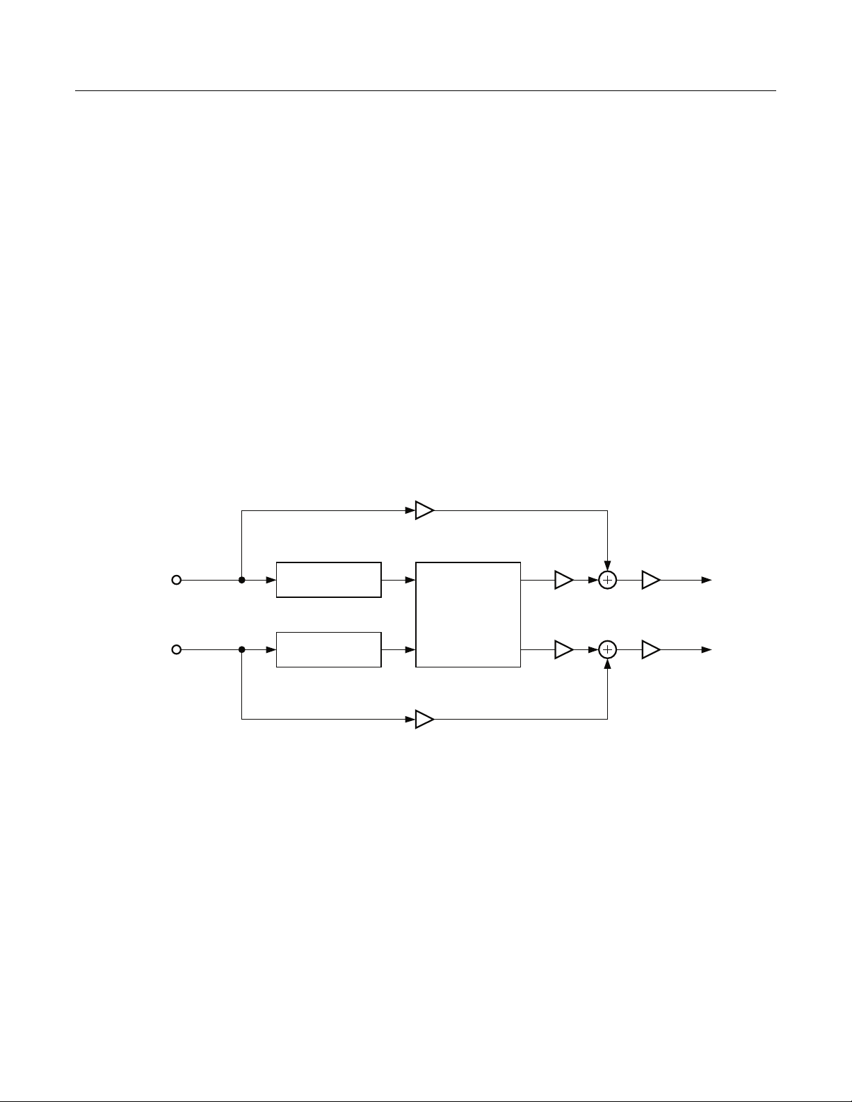
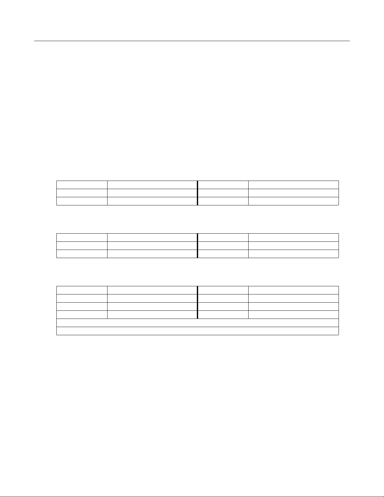
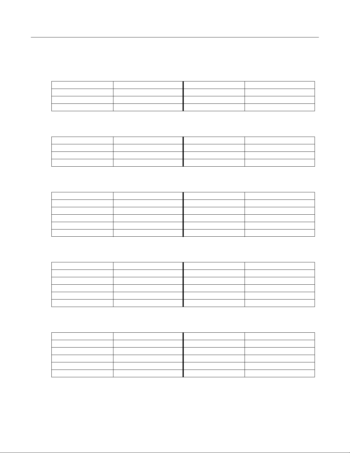
MiniVerb is a versatile stereo reverb found in many combination algorithms, but is equally useful on its
own because of its small size. The main control for this effect is the Room Type parameter. Room Type
changes the structure of the algorithm to simulate many carefully crafted room types and sizes. Spaces
characterized as booths, small rooms, chambers, halls and large spaces can be selected.
Dry
L Input
R Input
Figure 1 Simplified Block Diagram of MiniVerb
Each Room Type incorporates different diffusion, room size and reverb density settings. The Room Types
were designed to sound best when Diff Scale, Size Scale and Density are set to the default values of 1.00x.
If you want a reverb to sound perfect immediately, set the Diff Scale, Size Scale and Density parameters to
1.00x, pick a Room Type and you’ll be on the way to a great sounding reverb. But if you want to
experiment with new reverb flavors, changing the scaling parameters away from 1.00x can cause a subtle
(or drastic!) coloring of the carefully crafted Room Types.
Diffusion characterizes how the reverb spreads the early reflections out in time. At very low settings of
Diff Scale, the early reflections start to sound quite discrete, and at higher settings the early reflections are
seamless. Density controls how tightly the early reflections are packed in time. Low Density settings have
the early reflections grouped close together, and higher values spread the reflections for a smoother reverb.
L PreDelay
R PreDelay
Miniverb
Dry
Core
Wet Out Gain
L Output
R Output
12
Page 13
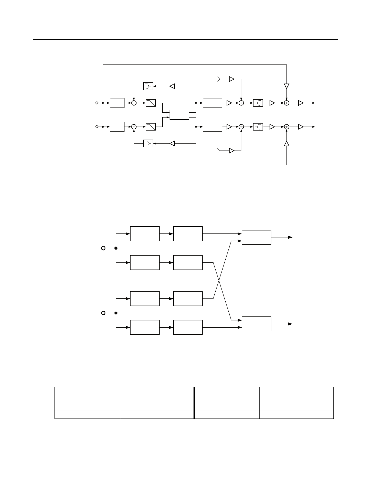
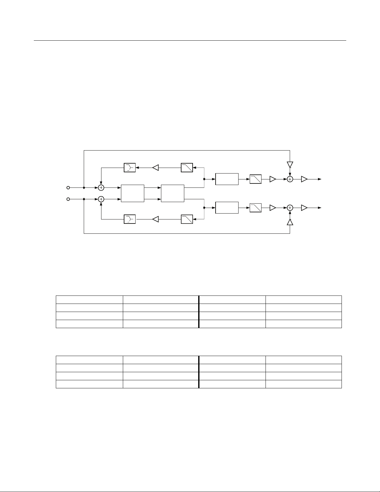
L Input
Dry
MiniVerb Balance
Pan
Wet
L Output
R Input
MiniVerb
Dry
Wet
Balance
Pan
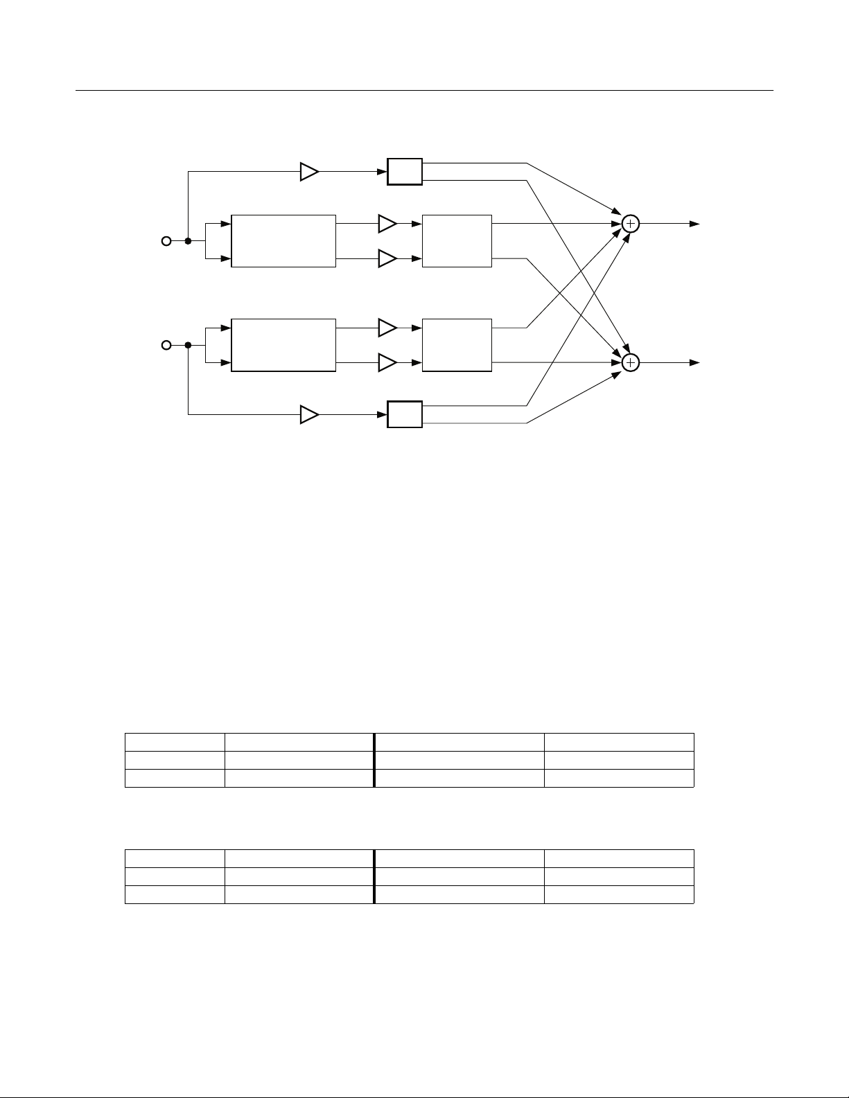
Figure 2 Simplified Block Diagram of Dual MiniVerb
Dual MiniVerb has a full MiniVerb, including Wet/Dry, Pre Delay and Out Gain controls, dedicated to
both the left and right channels. In Figure 2, the two blocks labeled MiniVerb contain a complete copy of
the contents of Figure 1. Dual MiniVerb gives you independent reverbs on both channels which has
obvious benefits for mono material. With stereo material, any panning or image placement can be
maintained, even in the reverb tails! This is pretty unusual behavior for a reverb, since even real halls will
rapidly delocalize acoustic images in the reverberation. Since maintaining image placement in the
reverberation is so unusual, you will have to carefully consider whether it is appropriate for your
particular situation. To use Dual MiniVerb to maintain stereo signals in this manner, set the reverb
parameters for both channels to the same values. The Dry Pan and Wet Bal parameters should be fully left
(-100%) for the left MiniVerb and fully right (100%) for the right MiniVerb.
MiniVerb Parameters:
Page 1
Wet/Dry 0 to 100%wet Out Gain Off, -79.0 to 24.0 dB
Rvrb Time 0.5 to 30.0 s, Inf HF Damping 8 to 25088 Hz
L Pre Dly 0 to 620 ms R Pre Dly 0 to 620 ms
R Output
Page 2
Room Type Hall1 Diff Scale 0.00 to 2.00x
Size Scale 0.00 to 4.00x
Density 0.00 to 4.00x
13
Page 14
Dual MiniVerb Parameters
Page 1
L Wet/Dry 0 to 100%wet R Wet/Dry 0 to 100%wet
L Out Gain Off, -79.0 to 24.0 dB R Out Gain Off, -79.0 to 24.0 dB
L Wet Bal -100 to 100% R Wet Bal -100 to 100%
L Dry Pan -100 to 100% R Dry Pan -100 to 100%
Page 2
L RoomType Hall1
L RvrbTime 0.5 to 30.0 s, Inf
L Diff Scl 0.00 to 2.00x L Density 0.00 to 4.00x
L Size Scl 0.00 to 4.00x L HF Damp 8 to 25088 Hz
L PreDlyL 0 to 620 ms L PreDlyR 0 to 620 ms
Page 3
R RoomType Hall1
R RvrbTime 0.5 to 30.0 s, Inf
R Diff Scl 0.00 to 2.00x R Density 0.00 to 4.00x
R Size Scl 0.00 to 4.00x R HF Damp 8 to 25088 Hz
R PreDlyL 0 to 620 ms R PreDlyR 0 to 620 ms
Wet/ Dry A simple mix of the reverb sound with the dry sound.
Out Gain The overall gain or amplitude at the output of the effect.
Rvrb Time The reverb time displayed is accurate for normal settings of the other parameters (HF
Damping = 25088kHz, and Diff Scale, Room Scale and Density = 1.00x). Changing Rvrb
Time to Inf creates an infinitely sustaining reverb.
HF Damping Reduces high frequency components of the reverb above the displayed cutoff frequency.
Removing higher reverb frequencies can often make rooms sound more natural.
L/R Pre Dly The delay between the start of a sound and the output of the first reverb reflections from
that sound. Longer predelays can help make larger spaces sound more realistic. Longer
times can also help improve the clarity of a mix by separating the reverb signal from the
dry signal, so the dry signal is not obscured. Likewise, the wet signal will be more audible
if delayed, and thus you can get by with a dryer mix while maintaining the same
subjective wet/dry level.
Room Type Changes the configuration of the reverb algorithm to simulate a wide array of carefully
designed room types and sizes. This parameter effectively allows you to have several
different reverb algorithms only a parameter change away. Smaller Room Types will
sound best with shorter Rvrb Times, and vice versa. (Note that since this parameter
changes the structure of the reverb algorithm, you don’t want to modulate it.)
14
Page 15

Diff Scale A multiplier which affects the diffusion of the reverb. At 1.00x, the diffusion will be the
normal, carefully adjusted amount for the current Room Type. Altering this parameter
will change the diffusion from the preset amount.
Size Scale A multiplier which changes the size of the current room. At 1.00x, the room will be the
normal, carefully tweaked size of the current Room Type. Altering this parameter will
change the size of the room, and thus will cause a subtle coloration of the reverb (since the
room’s dimensions are changing).
Density A multiplier which affects the density of the reverb. At 1.00x, the room density will be the
normal, carefully set amount for the current Room Type. Altering this parameter will
change the density of the reverb, which may color the room slightly.
Wet Bal In Dual MiniVerb, two mono signals (left and right) are fed into two separate stereo
reverbs. If you center the wet balance (0%), the left and right outputs of the reverb will be
sent to the final output in equal amounts. This will add a sense of spaciousness.
15
Page 16
3 Gated MiniVerb
A reverb and gate in series
PAUs: 2
This algorithm is a small reverb followed by a gate. The main control for the reverb is the Room Type
parameter. Room Type changes the structure of the algorithm to simulate many carefully crafted room
types and sizes. Spaces characterized as booths, small rooms, chambers, halls and large spaces can be
selected.
Each Room Type incorporates different diffusion, room size and reverb density settings. The Room Types
were designed to sound best when Diff Scale, Size Scale and Density are set to the default values of 1.00x.
If you want a reverb to sound perfect immediately, set the Diff Scale, Size Scale and Density parameters to
1.00x, pick a Room Type and you’ll be on the way to a great sounding reverb. But if you want experiment
with new reverb flavors, changing the scaling parameters away from 1.00x can cause a subtle (or drastic!)
coloring of the carefully crafted Room Types.
Diffusion characterizes how the reverb spreads the early reflection out in time. At very low settings of Diff
Scale, the early reflections start to sound quite discrete, and at higher settings the early reflections are
seamless. Density controls how tightly the early reflections are packed in time. Low Density settings have
the early reflections grouped close together, and higher values spread the reflections for a smoother reverb.
The gate turns the output of the reverb on and off based on the amplitude of the input signal.
A gate behaves like an on off switch for a signal. One or both input channels is used to control whether the
switch is on (gate is open) or off (gate is closed). The on/off control is called “side chain” processing. You
select which of the two input channels or both is used for side chain processing. When you select both
channels, the sum of the left and right input amplitudes is used. The gate is opened when the side chain
amplitude rises above a level that you specify with the Threshold parameter.
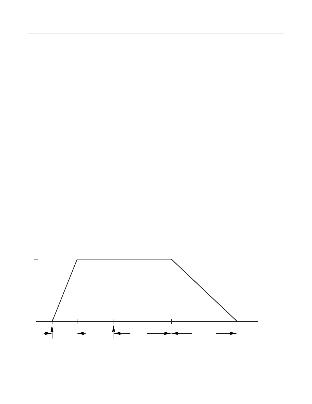
The gate will stay open for as long as the side chain signal is above the threshold. When the signal drops
below the threshold, the gate will remain open for the time set with the Gate Time parameter. At the end of
the Gate Time, the gate closes. When the signal rises above threshold, it opens again. What is happening is
that the gate timer is being constantly retriggered while the signal is above threshold.
1
0
attack
time
signal rises
above threshold
signal falls
below threshold
gate
time
release
time
Figure 3 Gate Behavior
16
Page 17
If Gate Duck is turned on, then the behavior of the gate is reversed. The gate is open while the side chain
signal is below threshold, and it closes when the signal rises above threshold.
If the gate opened and closed instantaneously, you would hear a large digital click, like a big knife switch
was being thrown. Obviously that’s not a good idea, so Gate Atk (attack) and Gate Rel (release) parameters
are use to set the times for the gate to open and close. More precisely, depending on whether Gate Duck is
Off or On, Gate Atk sets how fast the gate opens or closes when the side chain signal rises above the
threshold. The Gate Rel sets how fast the gate closes or opens after the gate timer has elapsed.
The Signal Dly parameter delays the signal being gated, but does not delay the side chain signal. By
delaying the main signal relative to the side chain signal, you can open the gate just before the main signal
rises above threshold. It’s a little like being able to pick up the telephone before it rings.
Parameters
Page 1
Wet/Dry 0 to 100%wet Out Gain Off, -79.0 to 24.0 dB
Rvrb Time 0.5 to 30.0s, Inf HF Damping 8 to 25088 Hz
L Pre Dly 0 to 620ms R Pre Dly 0 to 620 ms
Page 2
Room Type Hall1 Diff Scale 0.00 to 2.00x
Size Scale 0.00 to 4.00x
Density 0.00 to 4.00x
Page 3
Gate Thres -79.0 to 0.0 dB Gate Time 0 to 3000 ms
Gate Duck In or Out Gate Atk 0.0 to 228.0 ms
Gate Rel 0 to 3000 ms
GateSigDly 0.0 to 25.0 ms
|||||||||||||||||||||||||||||| Reduction
-dB 60 40 ❃ 16 ❃ 8 4 0
Wet/Dry A simple mix of the reverb sound with the dry sound. When set fully dry (0%), the gate is
still active.
Out Gain An overall level control of the effect’s output (applied after the gate).
Rvrb Time The reverb time displayed is accurate for normal settings of the other parameters (HF
Damping = 25088kHz, and Diff Scale, Room Scale and Density = 1.00x). Changing Rvrb
Time to Inf creates an infinitely sustaining reverb.
HF Damping Reduces high frequency components of the reverb above the displayed cutoff frequency.
Removing higher reverb frequencies can often make rooms sound more natural.
L/R Pre Dly The delay between the start of a sound and the output of the first reverb reflections from
that sound. Longer predelays can help make larger spaces sound more realistic. Longer
times can also help improve the clarity of a mix by separating the reverb signal from the
dry signal, so the dry signal is not obscured. Likewise, the wet signal will be more audible
17
Page 18

if delayed, and thus you can get by with a dryer mix while maintaining the same
subjective wet/dry level.
Room Type The configuration of the reverb algorithm to simulate a wide array of carefully designed
room types and sizes. This parameter effectively allows you to have several different
reverb algorithms only a parameter change away. Smaller Room Types will sound best
with shorter Rvrb Times, and vice versa. (Note that since this parameter changes the
structure of the reverb algorithm, you may not modulate it.)
Diff Scale A multiplier which affects the diffusion of the reverb. At 1.00x, the diffusion will be the
normal, carefully adjusted amount for the current Room Type. Altering this parameter
will change the diffusion from the preset amount.
Size Scale A multiplier which changes the size of the current room. At 1.00x, the room will be the
normal, carefully tweaked size of the current Room Type. Altering this parameter will
change the size of the room, and thus will cause a subtle coloration of the reverb (since the
room’s dimensions are changing).
Density A multiplier which affects the density of the reverb. At 1.00x, the room density will be the
normal, carefully set amount for the current Room Type. Altering this parameter will
change the density of the reverb, which may color the room slightly.
Gate Thres The input signal level in dB required to open the gate (or close the gate if Gate Duck is on).
Gate Duck When set to Off, the gate opens when the signal rises above threshold and closes when
the gate time expires. When set to On, the gate closes when the signal rises above
threshold and opens when the gate time expires.
Gate Time The time in seconds that the gate will stay fully on after the signal envelope rises above
threshold. The gate timer is started or restarted whenever the signal envelope rises above
threshold.
Gate Atk The attack time for the gate to ramp from closed to open (reverse if Gate Duck is On) after
the signal rises above threshold.
Gate Rel The release time for the gate to ramp from open to closed (reverse if Gate Duck is On)
after the gate timer has elapsed.
Signal Dly The delay in milliseconds (ms) of the reverb signal relative to the side chain signal. By
delaying the reverb signal, the gate can be opened before the reverb signal rises above the
gating threshold.
18
Page 19

Reverbs
4 Classic Place
5 Classic V erb
6 TQ Place
7 TQ V erb
8 Diffuse Place
9 Diffuse V erb
10 OmniPlace
11 OmniV erb
Reverb algorithms
PAUs: 2 (Classic) or 3 (others)
This set of 2- and 3-PAU algorithms can be divided into 2 groups: Verb and Place. Verb effects allow userfriendly control over medium to large spaces. Their decay times are controlled by Rvrb Time or
LateRvbTim parameters, and Room Types range from rooms to large areas. Place algorithms on the other
hand are optimized for small spaces. Decay time is controlled by the Absorption parameter, and Room
Types offers several booths.
Each reverb algorithm consists of a several components: a diffuser, an injector, predelay, an ambience
generator with feedback, and various filters. These components provide sonic building blocks for both the
body of the reverb and the early reflection portions.
The ambience generator is the heart of each reverb algorithm and creates most of the “late” reverb in
algorithms with an Early Reflections circuit. It consists of a complex arrangement of delay lines to disperse
the sound. By using feedback in conjunction with the ambience generator, a reverb tail is produced. The
length of this reverb tail is controlled by the Rvrb Time parameter in the Verb algorithms, or the
Absorption parameter in Place algorithms.
In order to create reverbs that are smoother and richer, some of the delays in the ambience generator are
moved by LFOs. The LFOs are adjusted by using the LFO Rate and LFO Depth controls. When used subtly,
unwanted artifacts such as flutteriness and ringiness that are inherent in digital reverbs can be reduced.
In the feedback loop of the ambience generator are filters that further enhance the sonic properties of each
reverb. A lowpass filter is controlled by HF Damping and mimics high frequency energy that is absorbed
as the sound travels around a room. A low shelving filter is controlled by LF Split and LF Time, which are
used to shorten or lengthen the decay time of low frequency energy.
At the beginning of each algorithm are diffusers. A diffuser creates an initial “smearing” quality on input
signals usually before the signal enters the ambience generating loop. The DiffAmtScl and DiffLenScl
parameters change the amount and the length of time that the sound is smeared. The Diffuse reverbs,
however, implement diffusion a little differently. See the sections on Diffuse Verb and Diffuse Place on
page 25 for detailed information.
Some algorithms use injector mechanisms when feeding a signal into the ambience generator. An injector
creates copies of the input signal at different delay intervals and feeds each copy into the ambience
generator at different points. This results in finer control over the onset of the reverb. By tapering the
amplitudes of early copies vs. late copies, the initial build of the reverb can be controlled. Inj Build controls
this taper. Negative values create a slower build, while positive values create a faster build. Inj Spread
scales the time intervals that the copies are made. Inj Skew (Omni reverbs) delays one channel relative to
the other before injecting into the ambience generator. Negative values delay the left side while positive
19
Page 20

values delay the right side. Inj LP controls the cutoff frequency of a 1-pole (6dB/oct) lowpass filter
associated with the injector.
Predelay can give the illusion that a space is more voluminous. Separate control over left and right
predelay is provided that can be used to de-correlate the center image, increasing reverb envelopment.
In addition to filters inside the ambience feedback loop, there also may be filters placed at the output of the
reverb including a low shelf, high shelf, and/or lowpass.
Algorithms that use Early Reflection circuits employ a combination of delays, diffusers, and filters to
create ambience that is sparser than the late portion of the reverb. These early reflections model the initial
near-discrete echoes rebounding directly off of near field surfaces before the reverb has a chance to become
diffuse. They add realism when emulating real rooms and halls.
Your starting point when creating a new reverb preset should be the Room Type parameter. This
parameter selects the basic type of reverb being. Due to the inherent complexity of reverb algorithms and
the sheer number of variables responsible for their character, the Room Type parameter provides
condensed preset collections of these variables. Each Room Type collection has been painstakingly
selected by Kurzweil engineers to provide the best sounding combination of mutually complementary
variables modeling an assortment of reverb families.
When you select a room type, an entire incorporated set of delay lengths and diffusion settings are
established within the algorithm. By using the Size Scale, DiffAmtScl, DiffLenScl, and Inj Spread
parameters, you may scale individual elements away from their pre-defined value. When set to 1.00x, each
of these elements is equivalent to its preset value as determined by the current Room Type.
Room Types with similar names in different reverb algorithms do not sound the same. For example, Hall1
in Diffuse Verb does not sound the same as Hall1 in TQ Verb.
The Size Scale parameter scales the inherent size of the reverb chosen by Room Type. For a true
representation of the selected Room Type size, set this to 1.00x. Scaling the size below this will create
smaller spaces, while larger scale factors will create large spaces. See Room Type for more detailed
information.
The InfinDecay switch is designed to override the Rvrb Time parameter and create a reverb tail with an
infinite decay time when On. However, certain HF Damping settings may reduce this effect, and cause the
tail to taper away.
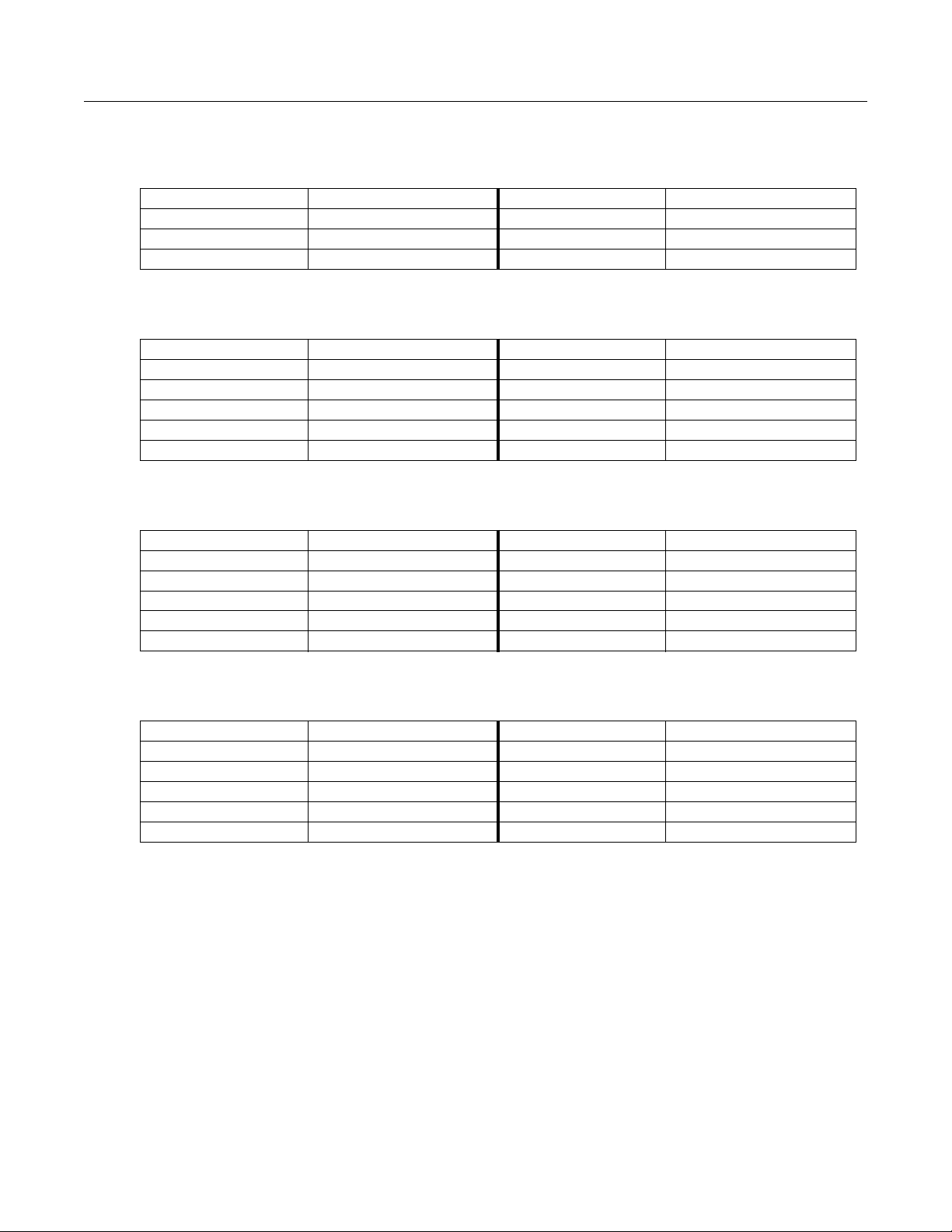
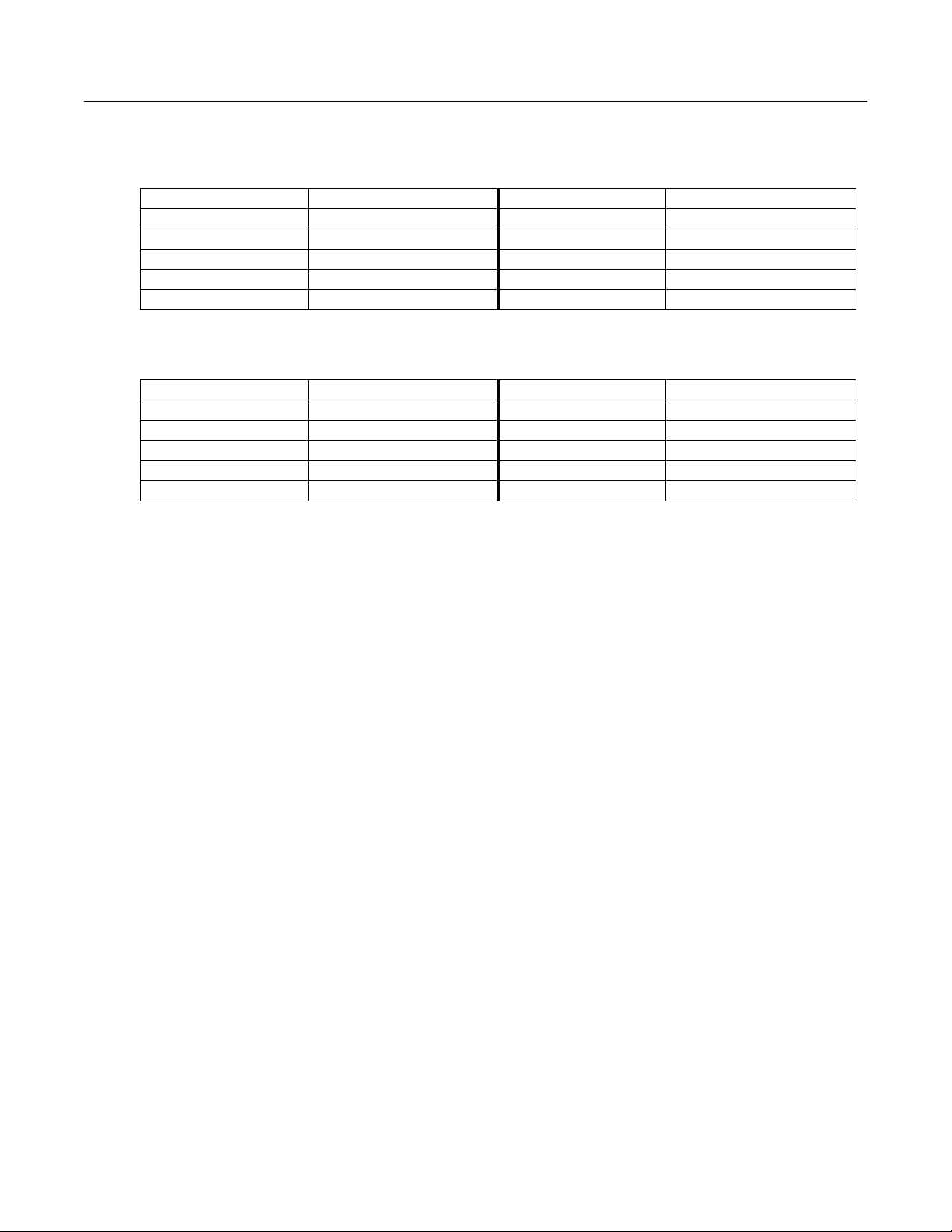
Classic Verb and Classic Place
Classic reverbs are 2-PAU algorithms with early reflections. The late portion consists of an input diffuser,
ambience generator with low shelving filters, lopass filters, and LFO moving delays, and predelay.
The early reflection portion consists of one delay per channel sent to its own output channel controlled by
E Dly L and E Dly R, and one delay per channel sent to its opposite output channel controlled be E Dly LX
and E Dly RX. Each of these delays also use a Diffuser. Diffusion lengths are separately controlled by
E DifDly L, E DifDly R, E DifDly LX, and E DifDly RX while diffusion amounts are all adjusted with
E DiffAmt.
The late reverb and early reflection portions are independently mixed together with the Late Lvl and
EarRef Lvl controls. The wet signal is passed through a final high shelving filter before being mixed with
the dry signal.
20
Page 21
L Input
DiffAmtScl
DiffLenScl
Diffusor
LF Mult
HF Damping
Rvrb Time
Absorption
L ER Output
L Pre Dly
EarRef Lvl
Late
Lvl
Treble
Dry
Wet
L Output
Ambience
Rvrb Time
Absorption
R Pre Dly
R ER Output
R Input
DiffAmtScl
DiffLenScl
Diffusor
HF Damping
LF Mult
Figure 4 Signal flow of Classic Verb and Classic Place
E DfDlyScl
E DiffAmt
(Apply to all Diffusors)
E DifDlyL
E Dly L
L Input
E Dly LX
Diffusor
E DifDlyLX
Diffusor
E DifDlyR
Late
Lvl
EarRef Lvl
Treble
Blend
E Blend X
Out Gain
R Output
Wet
Dry
L ER Output
E Dly RX
R Input
E Dly R
Diffusor
E DifDlyRX
Diffusor
E Blend X
Blend
Figure 5 Early reflection portion of Classic Verb and Classic Place
Parameters for Classic Verb and Classic Place:
Page 1 (Classic Verb)
Wet/Dry -100 to 100% Out Gain Off; -79.0 to 24.0 dB
Rvrb Time 0.00 to 60.00 s EarRef Lvl -100 to 100%
HF Damping 0 to 25088 Hz Late Lvl -100 to 100%
L Pre Dly 0.0 to 230.0 ms R Pre Dly 0.0 to 230.0 ms
R ER Output
21
Page 22
Page 1 (Classic Place)
Wet/Dry -100 to 100% Out Gain Off; -79.0 to 24.0 dB
Absorption 0 to 100 % EarRef Lvl -100 to 100%
HF Damping 0 to 25088 Hz Late Lvl -100 to 100%
L Pre Dly 0.0 to 230.0 ms R Pre Dly 0.0 to 230.0 ms
Page 2 (Classic Verb)
Room Type Hall1, ... DiffAmtScl 0.00 to 2.00 x
Size Scale 0.01 to 2.00x DiffLenScl 0.00 to 2.00 x
InfinDecay On or Off LFO Rate 0.01 to 10.00 Hz
LFO Depth 0.0 to 100.0 ct
TrebShlf F 8 to 25088 Hz LF Split 8 to 25088 Hz
TrebShlf G -79.0 to 24.0 dB LF Time 0.50 to 1.50 x
Page 2 (Classic Place)
Room Type Hall1, ... DiffAmtScl 0.00 to 2.00 x
Size Scale 0.01 to 2.00x DiffLenScl 0.00 to 2.00 x
LFO Rate 0.01 to 10.00 Hz
LFO Depth 0.0 to 100.0 ct
TrebShlf F 8 to 25088 Hz LF Split 8 to 25088 Hz
TrebShlf G -79.0 to 24.0 dB LF Time 0.50 to 1.50 x
Page 3
E DfDlyScl 0.00 to 2.00 x E X Blend 0 to 100 %
E DiffAmt -100 to 100 %
E Dly L 0.0 to 720.0 ms E Dly R 0.0 to 720.0 ms
E Dly LX 0.0 to 720.0 ms E Dly RX 0.0 to 720.0 ms
E DifDlyL 0.0 to 160.0 ms E DifDlyR 0.0 to 160.0 ms
E DifDlyLX 0.0 to 230.0 ms E DifDlyRX 0.0 to 230.0 ms
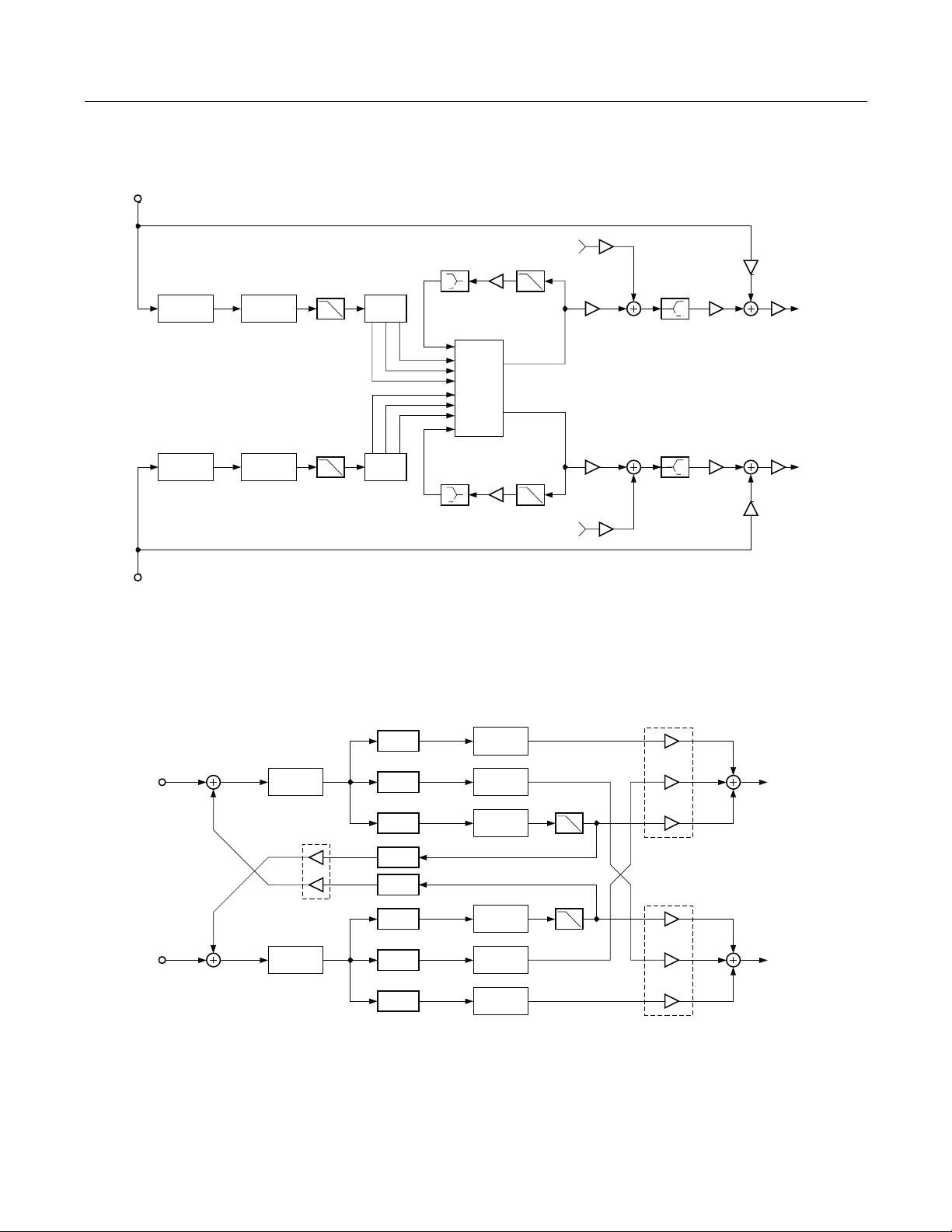
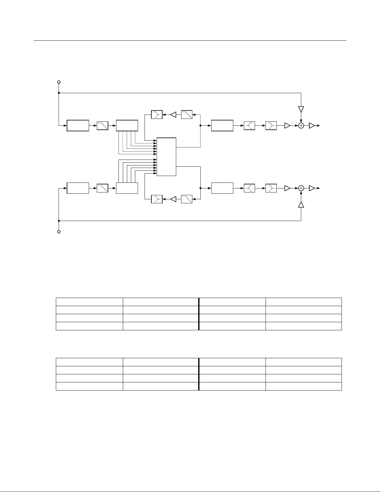
TQ Verb and TQ Place:
TQ reverbs are 3-PAU algorithms with early reflections. The late portion consists of an input diffuser,
injector, ambience generator with a lopass filter, low shelving filter, and LFO moving delays, and predelay.
The early reflection portion combines a combination of delays, diffusers, and feedback outlined by
Figure 7. The relative delay lengths are all fixed but are scalable with the E Dly Scl parameter. Relative
diffusion lengths are also fixed, and are scalable with the E DfLenScl parameter. Diffusion amount are
adjusted with E DiffAmt. The E Build parameter ramps the gains associated with each delay line in a way
that changes the characteristic of the onset of the early reflections. Negative amounts create a slower onset
while positive amount create a faster onset.
The late reverb and early reflection portions are independently mixed together with the Late Lvl and
EarRef Lvl controls. The wet signal is passed through a final high shelving filter before being mixed with
the dry signal.
22
Page 23
L Input
Reverb Time
Absorption
DiffAmtScl
DiffLenScl
Diffuser
DiffAmtScl
DiffLenScl
Diffuser
Inj LP
L Pre Dly
Inj LP
R Pre Dly
InjBuild
InjSpread
Injector
Injector
InjBuild
InjSpread
LF Mult
LF Mult
Reverb Time
HF Damping
Ambience
HF Damping
Absorption
R Input
Figure 6 Signal flow of TQ Verb and TQ Place
E Dly Scl
(Applies to
All Delays)
Delay
Diffusor
L ER Output
R ER Output
EarRef Lvl
Late Lvl
Late Lvl
EarRef Lvl
Treble
Treble
Wet
Wet
Dry
Out
Gain
Out
Gain
Dry
L Output
R Output
L Input
E PreDly L
E Fdbk Amt
Delay
Delay
Diffusor
Diffusor
Delay
Delay
Diffusor
Diffusor
Diffusor
R Input
E PreDly R
Delay
Delay
Delay
Figure 7 Early reflection portion of TQ Verb and TQ Place
L ER Output
E Build
E Build
R ER Output
23
Page 24
Parameters for TQ Verb and TQ Place:
Page 1 (TQ Verb)
Wet/Dry -100 to 100% Out Gain Off; -79.0 to 24.0 dB
Rvrb Time 0.00 to 60.00 s EarRef Lvl -100 to 100%
HF Damping 0 to 25088 Hz Late Lvl -100 to 100%
L Pre Dly 0.0 to 230.0 ms R Pre Dly 0.0 to 230.0 ms
Page 1 (TQ Place)
Wet/Dry -100 to 100% Out Gain Off; -79.0 to 24.0 dB
Absorption 0 to 100 % EarRef Lvl -100 to 100%
HF Damping 0 to 25088 Hz Late Lvl -100 to 100%
L Pre Dly 0.0 to 230.0 ms R Pre Dly 0.0 to 230.0 ms
Page 2 (TQ Verb)
Room Type Hall1, ... TrebShlf F 8 to 25088 Hz
Size Scale 0.00 to 2.50x TrebShlf G -79.0 to 24.0 dB
InfinDecay On or Off DiffAmtScl 0.00 to 2.00 x
DiffLenScl 0.00 to 2.50 x
LF Split 8 to 25088 Hz LFO Rate 0.01 to 10.00 Hz
LF Time 0.50 to 1.50 x LFO Depth 0.0 to 100.0 ct
Page 2 (TQ Place)
Room Type Hall1, ... TrebShlf F 8 to 25088 Hz
Size Scale 0.00 to 2.50x TrebShlf G -79.0 to 24.0 dB
DiffAmtScl 0.00 to 2.00 x
DiffLenScl 0.00 to 2.50 x
LF Split 8 to 25088 Hz LFO Rate 0.01 to 10.00 Hz
LF Time 0.50 to 1.50 x LFO Depth 0.0 to 100.0 ct
Page 3
Inj Build -100 to 100 % Inj LP 8 to 25088 Hz
Inj Spread 0.00 to 2.50 x
E DiffAmt -100 to 100 % E Build -100 to 100 %
E DfLenScl 0.00 to 2.50 x E Fdbk Amt -100 to 100 %
E DlyScl 0.00 to 2.50 x E HF Damp 8 to 25088 Hz
E PreDlyL 0.0 to 150.0 ms E PreDlyR 0.0 to 150.0 ms
24
Page 25
Diffuse Verb and Diffuse Place
Diffuse reverbs are 3-PAU algorithms and are characterized as such because of the initial burst of diffusion
inherent in the onset of the reverb. The diffusion consists of an input diffuser, ambience generator with a
lopass filter, low shelving filter, and LFO moving delays, and predelay.
In the diffuse reverbs, the diffuser is implemented a little differently. The diffuser is just inside the
ambience generation loop, so changes in diffusion create changes the reverb decay. The diffuse reverbs
also offer DiffExtent and Diff Cross parameters. DiffExtent selects one of seven arbitrary gate time lengths
of the initial diffusion burst, while Diff Cross adjusts the combination of left and right channels that are
diffused.
LateRvbTim
Absorption
LateRvbTim
Absorption
HF Damping
HF Damping
L Pre Dly
R Pre Dly
Lopass
Lopass
Wet
Wet
L Input
R Input
LF Mult
DiffExtent
Diff Cross
Diffusor Ambience
DiffAmtScl
DiffLenScl
LF Mult
Figure 8 Signal flow of Diffuse Verb and Diffuse Place
Parameters for Diffuse Verb and Diffuse Place:
Page 1 (Diffuse Verb)
Wet/Dry -100 to 100% Out Gain Off; -79.0 to 24.0 dB
LateRvbTim 0.00 to 60.00 s
HF Damping 0 to 25088 Hz Lopass 8 to 25088 Hz
L Pre Dly 0.0 to 230.0 ms R Pre Dly 0.0 to 230.0 ms
Dry
L Output
Out Gain
R Output
Dry
Page 1 (Diffuse Place)
Wet/Dry -100 to 100% Out Gain Off; -79.0 to 24.0 dB
Absorption 0 to 100 %
HF Damping 0 to 25088 Hz Lopass 8 to 25088 Hz
L Pre Dly 0.0 to 230.0 ms R Pre Dly 0.0 to 230.0 ms
25
Page 26
Page 2 (Diffuse Verb)
Room Type Hall1, ... DiffExtent 1 to 7 x
Size Scale 0.01 to 2.50x Diff Cross -100 to 100 %
InfinDecay On or Off DiffAmtScl 0.00 to 2.00 x
DiffLenScl 0.01 to 2.50 x
LF Split 8 to 25088 Hz LFO Rate 0.01 to 10.00 Hz
LF Time 0.50 to 1.50 x LFO Depth 0.0 to 100.0 ct
Page 2 (Diffuse Place)
Room Type Hall1, ... DiffExtent 1 to 7 x
Size Scale 0.01 to 2.50x Diff Cross -100 to 100 %
DiffAmtScl 0.00 to 2.00 x
DiffLenScl 0.01 to 2.50 x
LF Split 8 to 25088 Hz LFO Rate 0.01 to 10.00 Hz
LF Time 0.50 to 1.50 x LFO Depth 0.0 to 100.0 ct
OmniVerb and OmniPlace:
Omni reverbs are 3-PAU algorithms that consists of an input diffuser, injector, ambience generator with a
lopass filter, low shelving filter, and LFO moving delays, and predelay.
The Expanse parameter adjusts the amount of reverb energy that is fed to the edges of the stereo image. A
value of 0% concentrates energy in the center of the image, while non-zero values spread it out. Positive
and negative values impose different characteristics on the reverb image.
At the output of the reverb are a pair each of low shelving and high shelving filters.
26
Page 27
L Input
DiffAmtScl
DiffLenScl
Diffuser
Lopass
Inj Build
Inj Spread
Inj Skew
Injector
LF Mult
Reverb Time
Absorption
Ambience
HF Damping
L Pre Dly
Treble
Bass
Wet
Dry
Out
Gain
L Output
DiffAmtScl
DiffLenScl
Diffuser
Lopass
Injector R Pre Dly
Inj Build
Inj Spread
Inj Skew
LF Mult
Reverb Time
Absorption
HF Damping
Treble
Bass
Wet
R Input
Figure 9 Signal flow of OmniVerb and OmniPlace
Parameters for OmniVerb and OmniPlace:
Page 1 (OmniVerb)
Wet/Dry -100 to 100% Out Gain Off; -79.0 to 24.0 dB
Rvrb Time 0.00 to 60.00 s
HF Damping 0 to 25088 Hz Lopass 8 to 25088 Hz
L Pre Dly 0.0 to 230.0 ms R Pre Dly 0.0 to 230.0 ms
Page 1 (OmniPlace)
Out
Gain
Dry
R Output
Wet/Dry -100 to 100% Out Gain Off; -79.0 to 24.0 dB
Absorption 0 to 100 %
HF Damping 0 to 25088 Hz Lopass 8 to 25088 Hz
L Pre Dly 0.0 to 230.0 ms R Pre Dly 0.0 to 230.0 ms
27
Page 28
Page 2 (OmniVerb)
Room Type Hall1, ... Expanse -100 to 100 %
Size Scale 0.00 to 2.50x
InfinDecay On or Off DiffAmtScl 0.00 to 2.00 x
DiffLenScl 0.00 to 4.50 x
LF Split 8 to 25088 Hz LFO Rate 0.01 to 10.00 Hz
LF Time 0.50 to 1.50 x LFO Depth 0.0 to 100.0 ct
Page 2 (OmniPlace)
Room Type Hall1, ... Expanse -100 to 100 %
Size Scale 0.00 to 2.50x
DiffAmtScl 0.00 to 2.00 x
DiffLenScl 0.00 to 4.50 x
LF Split 8 to 25088 Hz LFO Rate 0.01 to 10.00 Hz
LF Time 0.50 to 1.50 x LFO Depth 0.0 to 100.0 ct
Page 3
TrebShlf F 8 to 25088 Hz
Inj Build -100 to 100 % TrebShlf G -79.0 to 24.0 dB
Inj Spread 0.00 to 4.50 x BassShlf F 8 to 25088 Hz
Inj Skew -200 to 200 ms BassShlf G -79.0 to 24.0 dB
Parameters
Absorption This controls the amount of reflective material that is in the space being
emulated, much like an acoustical absorption coefficient. The lower the
setting, the longer it will take for the sound to die away. A setting of 0%
will cause an infinite decay time.
Rvrb Time Adjusts the basic decay time of the late portion of the reverb.
LateRvbTim Adjusts the basic decay time of the late portion of the reverb after
diffusion.
HF Damping This controls the amount of high frequency energy that is absorbed as the
reverb decays. The values set the cutoff frequency of the 1 pole (6dB/oct)
lowpass filter within the reverb feedback loop.
L Pre Dly, R Pre Dly These control the amount that each channel of the reverb is delayed
relative to the dry signal. Setting different lengths for both channels can
de-correlate the center portion of the reverb image and make it seem
wider. This only affects the late reverb in algorithms that have early
reflections.
Lopass Controls the cutoff frequency of a 1 pole (6dB/oct) lowpass filter at the
output of the reverb. This only affects the late reverb in algorithms that
have early reflections.
28
Page 29

EarRef Lvl The mix level of the early reflection portion of algorithms offering early
reflections.
Late Lvl The mix level of the late reverb portion of algorithms offering early
reflections.
Room Type This parameter selects the basic type of reverb being emulated, and
should be your starting point when creating your own reverb presets.
Due to the inherent complexity of reverb algorithms and the sheer
number of variables responsible for their character, the Room Type
parameter provides condensed preset collections of these variables. Each
Room Type preset has been painstakingly selected by Kurzweil engineers
to provide the best sounding collection of mutually complementary
variables modeling an assortment of reverb families. When a room type is
selected, an entire incorporated set of delay lengths and diffusion settings
are established within the algorithm. By using the Size Scale, DiffAmtScl,
DiffLenScl, and Inj Spread parameters, you may scale individual
elements away from their preset value. When set to 1.00x, each of these
elements are accurately representing their preset values determined by
the current Room Type.
Room Types with similar names in different reverb algorithms do not
sound the same. For example, Hall1 in Diffuse Verb does not sound the
same as Hall1 in TQ Verb.
Size Scale Scales the inherent size of the reverb chosen by Room Type. For a true
representation of the selected Room Type size, set this to 1.00x. Scaling
the size below this will create smaller spaces, while larger scale factors
will create large spaces. See Room Type for more detailed information.
InfinDecay Found in “Verb” algorithms. When turned On, the reverb tail will decay
indefinitely. When turned Off, the decay time is determined by the Rvrb
Time or LateRvbTim parameters.
LF Split Used in conjunction with LF Time. This controls the upper frequency
limit of the low frequency decay time multiplier. Energy below this
frequency will decay faster or slower depending on the LF Time
parameter.
LF Time Used in conjunction with LF Split. This modifies the decay time of the
energy below the LF Split frequency. A setting of 1.00x will make low
frequency energy decay at the rate determined by the decay time. Higher
values will cause low frequency energy to decay slower, and lower values
will cause it to decay more quickly.
TrebShlf F The frequency of a high shelving filter at the output of the late reverb.
TrebShlf G The gain of a high shelving filter at the output of the late reverb.
BassShlf F The frequency of a low shelving filter at the output of the late reverb.
BassShlf G The gain of a low shelving filter at the output of the late reverb.
DiffAmtScl The amount of diffusion at the onset of the reverb. For true representation
of the selected Room Type diffusion amount, set to 1.00x.
DiffLenScl The length of the diffusion at the onset of the reverb. For true
representation of the selected Room Type diffusion length, set to 1.00x.
29
Page 30

DiffExtent The onset diffusion duration. Higher values create longer diffuse bursts
at the onset of the reverb.
Diff Cross The onset diffusion cross-coupling character. Although subtle, this
parameter bleeds left and right channels into each other during onset
diffusion, and also in the body of the reverb. 0% setting will disable this.
Increasing this value in either the positive or negative direction will
increase its affect.
Expanse Amount of late reverb energy biased toward the edges of the stereo
image. A setting of 0% will bias energy towards the center. Moving away
from 0% will bias energy towards the sides. Positive and negative values
will have a different character.
LFO Rate The rate at which certain reverb delay lines move. See LFO Depth for
more information.
LFO Depth Adjusts the detuning depth in cents caused by a moving reverb delay
line. Moving delay lines can imitate voluminous flowing air currents and
reduce unwanted artifacts like ringing and flutter when used properly.
Depth settings under 1.5ct with LFO Rate settings under 1.00Hz are
recommended for modeling real spaces. High depth settings can create
chorusing qualities, which won’t be unsuitable for real acoustic spaces,
but can nonetheless create interesting effects. Instruments that have little
if no inherent pitch fluctuation (like piano) are much more sensitive to
this LFO than instruments that normally have a lot of vibrato (like voice)
or non-pitched instruments (like snare drum).
Inj Build Used in conjunction with Inj Spread, this adjusts the envelope of the onset
of the reverb. Specifically, it tapers the amplitudes of a series of delayed
signals injected into the body of the reverb. Values above 0% will produce
a faster build, while values below 0% will cause the build to be more
gradual.
Inj Spread Used in conjunction with Inj Build, this scales the length of the series of
delays injected into the body of the reverb. For a true representation of
the selected Room Type injector spread, set this to 1.00x.
Inj LP The cutoff frequency of a 1 pole (6dB/oct) lowpass filter applied to the
signal being injected into the body of the reverb.
Inj Skew The amount of delay applied to either the left or right channel of the
reverb injector. Positive values delay the right channel while negative
values delay the left channel.
E DiffAmt The amount of diffusion applied to the early reflection network.
E DfLenScl The length of diffusion applied to the early reflection network. This is
influenced by E PreDlyL and E PreDlyR.
E Dly Scl Scales the delay lengths inherent in the early reflection network.
E Build The envelope of the onset of the early reflections. Values above 0% will
create a faster attack while values below 0% will create a slower attack.
E Fdbk Amt The amount of the output of an early reflection portion that is fed back
into the input of the opposite channel in front of the early predelays.
Overall, it lengthens the decay rate of the early reflection network.
Negative values polarity invert the feedback signal.
30
Page 31

E HF Damp The cutoff frequency of a 1 pole (6dB/oct) lowpass filter applied to the
early reflection feedback signal.
E PreDlyL, E PreDlyR The amount of delay in early reflections relative to the dry signal. These
are independent of the late reverb predelay times, but will influence
E Dly Scl.
E Dly L, E Dly R The left and right early reflection delays fed to the same output channels.
E Dly LX, E Dly RX The left and right early reflection delays fed to the opposite output
channels.
E DifDlyL, E DifDlyR The diffusion delays of the diffusers on delay taps fed to the same output
channels.
E DifDlyLX, E DifDlyRX The diffusion delays of the diffusers on delay taps fed to the opposite
output channels.
E X Blend The balance between early reflection delay tap signals with diffusers fed
to their same output channel, and those fed to opposite channels. 0% will
only allow delay taps being fed to opposite output channels to be heard,
while 100% allows only delay taps going to the same channels to be
heard.
31
Page 32

12 Panaural Room
Room reverberation algorithm
PAUs: 3
The Panaural Room reverberation is implemented using a special network arrangement of many delay lines that guarantees colorless sound. The reverberator is inherently stereo with each input injected into the “room” at multiple locations. The signals entering the reverberator first pass through a shelving bass equalizer with a range of +/-15dB. To shorten the decay time of high frequencies relative to mid frequencies, lowpass filters controlled by HF Damping are distributed throughout the network. Room Size scales all the delay times of the network (but not the Pre Dly or Build Time), to change the simulated room dimension over a range of 1 to 16m. Decay Time varies the feedback gains to achieve decay times from 0.5 to 100 seconds. The Room Size and Decay Time controls are interlocked so that a chosen Decay Time will be maintained while Room Size is varied. A two input stereo mixer, controlled by Wet/Dry and Out Gain, feeds the output.
Dry
L Input
R Input
PreDelay
PreDelay
Dry
Reverb
Wet
Out Gain
L Output
R Output
Figure 10 Simplified block diagram of Panaural Room
The duration and spacing of the early reflections are influenced by Room Size and Build Time, while the
number and relative loudness of the individual reflections are influenced by Build Env. When Build Env is
near 0% or 100%, fewer reflections are created. The maximum number of important early reflections, 13, is
achieved at a setting of 50%.
To get control over the growth of reverberation, the left and right inputs each are passed through an
“injector” that can extend the source before it drives the reverberator. Only when Build Env is set to 0% is
the reverberator driven in pure stereo by the pure dry signal. For settings of Build Env greater than 0%, the
reverberator is fed multiple times. Build Env controls the injector so that the reverberation begins abruptly
(0%), builds immediately to a sustained level (50%), or builds gradually to a maximum (100%). Build Time
varies the injection length over a range of 0 to 500ms. At a Build Time of 0ms, there is no extension of the
build time. In this case, the Build Env control adjusts the density of the reverberation, with maximum
density at a setting of 50%. In addition to the two build controls, there is an overall Pre Dly control that can
delay the entire reverberation process by up to 500ms.
32
Page 33

Parameters
Page 1
Wet/Dry 0 to 100%wet Out Gain Off, -79.0 to 24.0
Room Size 1.0 to 16.0 m
Pre Dly 0 to 500 ms Decay Time 0.5 to 100.0 s
HF Damping 8 to 25088 Hz
Page 2
Bass Gain -15 to 15 dB Build Time 0 to 500 ms
Build Env 0 to 100%
Wet/Dry The amount of the stereo reverberator (wet) signal relative to the original input (dry)
signal to be output. The dry signal is not affected by the Bass Gain control. The wet signal
is affected by the Bass Gain control and by all the other reverberator controls. The balance
between wet and dry signals is an extremely important factor in achieving a good mix.
Emphasizing the wet signal gives the effect of more reverberation and of greater distance
from the source.
Out Gain The overall output level for the reverberation effect, and controls the level for both the wet
and dry signal paths.
Decay Time The reverberation decay time (mid-band “RT60”), the time required before the
reverberation has died away to 60dB below its “running” level. Adjust decay time
according to the tempo and articulation of the music and to taste.
HF Damping Adjusts lowpass filters in the reverberator so that high frequencies die away more quickly
than mid and low frequencies. This shapes the reverberation for a more natural, more
acoustically accurate sound.
Bass Gain Shapes the overall reverberation signal’s bass content, but does not modify the decay
time. Reduce the bass for a less muddy sound, raise it slightly for a more natural acoustic
effect.
Room Size Choosing an appropriate room size is very important in getting a good reverberation
effect. For impulsive sources, such as percussion instruments or plucked strings, increase
the size setting until discrete early reflections become audible, and then back it off slightly.
For slower, softer music, use the largest size possible. At lower settings, Room Size leads
to coloration, especially if the Decay Time is set too high.
Pre Dly Introducing predelay creates a gap of silence between that allows the dry signal to stand
out with greater clarity and intelligibility against the reverberant background. This is
especially helpful with vocal or classical music.
Build Time Similar to predelay, but more complex, larger values of Build Time slow down the
building up of reverberation and can extend the build up process. Experiment with Build
Time and Build Env and use them to optimize the early details of reverberation. A Build
Time of 0ms and a Build Env of 50% is a good default setting that yields a fast arriving,
maximally dense reverberation.
Build Env When Build Time has been set to greater than about 80ms, Build Env begins to have an
audible influence on the early unfolding of the reverberation process. For lower density
reverberation that starts cleanly and impulsively, use a setting of 0%. For the highest
33
Page 34

density reverberation, and for extension of the build up period, use a setting of 50%. For
an almost reverse reverberation, set Build Env to 100%. You can think of Build Env as
setting the position of a see-saw. The left end of the see-saw represents the driving of the
reverberation at the earliest time, the pivot point as driving the reverberation at mid-point
in the time sequence, and the right end as the last signal to drive the reverberator. At
settings near 0%, the see-saw is tilted down on the right: the reverberation starts abruptly
and the drive drops with time. Near 50%, the see-saw is level and the reverberation is
repetitively fed during the entire build time. At settings near 100%, the see-saw is tilted
down on the left, so that the reverberation is hit softly at first, and then at increasing level
until the end of the build time.
34
Page 35

13 Stereo Hall
A stereo hall reverberation algorithm.
PAUs: 3
The Stereo Hall reverberation is implemented using a special arrangement of allpass networks and delay lines which reduces coloration and increases density. The reverberator is inherently stereo with each input injected into the “room” at multiple locations. To shorten the decay time of low and high frequencies relative to mid frequencies, bass equalizers and lowpass filters, controlled by Bass Gain and by HF Damping, are placed within the network. Room Size scales all the delay times of the network (but not the Pre Dly or Build Time), to change the simulated room dimension over a range of 10 to 75m. Decay Time varies the feedback gains to achieve decay times from 0.5 to 100 seconds. The Room Size and Decay Time controls are interlocked so that a chosen Decay Time will be maintained while Room Size is varied. At smaller sizes, the reverb becomes quite colored and is useful only for special effects. A two input stereo mixer, controlled by Wet/Dry and Out Gain, feeds the output. The Lowpass control acts only on the wet signal and can be used to smooth out the reverb high end without modifying the reverb decay time at high frequencies.
Dry
L Input
R Input
PreDelay
PreDelay
Reverb
Dry
Wet
Out Gain
L Output
R Output
Figure 11 Simplified block diagram of Stereo Hall
Within the reverberator, certain delays can be put into a time varying motion to break up patterns and to
increase density in the reverb tail. Using the LFO Rate and Depth controls carefully with longer decay
times can be beneficial. But beware of the pitch shifting artifacts which can accompany randomization
when it is used in greater amounts. Also within the reverberator, the Diffusion control can reduce the
diffusion provided by some allpass networks. While the reverb will eventually reach full diffusion
regardless of the Diffusion setting, the early reverb diffusion can be reduced, which sometimes is useful to
help keep the dry signal “in the clear.”
The reverberator structure is stereo and requires that the dry source be applied to both left and right
inputs. If the source is mono, it should still be applied (pan centered) to both left and right inputs. Failure
to drive both inputs will result in offset initial reverb images and later ping-ponging of the reverberation.
Driving only one input will also increase the time required to build up reverb density.
To gain control over the growth of reverberation, the left and right inputs each are passed through an
“injector” that can extend the source before it drives the reverberator. Only when Build Env is set to 0% is
the reverberator driven in pure stereo by the pure dry signal. For settings of Build Env greater than 0%, the
reverberator is fed multiple times. Build Env controls the injector so that the reverberation begins abruptly
(0%), builds immediately to a sustained level (50%), or builds gradually to a maximum (100%). Build Time
35
Page 36

varies the injection length over a range of 0 to 500ms. At a Build Time of 0ms, there is no extension of the
build time. In this case, the Build Env control adjusts the density of the reverberation, with maximum
density at a setting of 50%. In addition to the two build controls, there is an overall Pre Dly control that can
delay the entire reverberation process by up to 500ms.
Parameters
Page 1
Wet/Dry 0 to 100%wet Out Gain Off, -79.0 to 24.0 dB
Room Size 2.0 to 15.0 m Diffusion 0 to 100%
Pre Dly 0 to 500 ms Decay Time 0.5 to 100.0 ms
HF Damping 8 to 25088 Hz
Page 2
Bass Gain -15 to 0 dB Build Time 0 to 500 ms
Lowpass 8 to 25088 Hz Build Env 0 to 100%
LFO Rate 0.00 to 5.10 Hz
LFO Depth 0.00 to 10.20 ct
Wet/Dry The amount of the stereo reverberator (wet) signal relative to the original input
(dry) signal to be output. The dry signal is not affected by the HF Roll control.
The wet signal is affected by the HF Roll control and by all the other
reverberator controls. The balance between wet and dry signals is an extremely
important factor in achieving a good mix. Emphasizing the wet signal gives the
effect of more reverberation and of greater distance from the source.
36
Out Gain The overall output level for the reverberation effect, and controls the level for
both the wet and dry signal paths.
Decay Time The reverberation decay time (mid-band “RT60”), the time required before the
reverberation has died away to 60dB below its “running” level. Adjust decay
time according to the tempo and articulation of the music and to taste.
HF Damping Adjusts lowpass filters in the reverberator so that high frequencies die away
more quickly than mid and low frequencies. This shapes the reverberation for a
more natural, more acoustically accurate sound.
Bass Gain Adjusts bass equalizers in the reverberator so that low frequencies die away
more quickly than mid and high frequencies. This can be used to make the
reverberation less muddy.
Lowpass Used to shape the overall reverberation signal’s treble content, but does not
modify the decay time. Reduce the treble for a softer, more acoustic sound.
Room Size Choosing an appropriate room size is very important in getting a good
reverberation effect. For impulsive sources, such as percussion instruments or
plucked strings, increase the size setting until discrete early reflections become
audible, and then back it off slightly. For slower, softer music, use the largest
size possible. At lower settings, RoomSize leads to coloration, especially if the
DecayTime is set too high.
Page 37

Pre Dly Introducing predelay creates a gap of silence between that allows the dry signal
to stand out with greater clarity and intelligibility against the reverberant
background. This is especially helpful with vocal or classical music.
Build Time Similar to predelay, but more complex, larger values of BuildTime slow down
the building up of reverberation and can extend the build up process.
Experiment with BuildTime and BuildEnv and use them to optimize the early
details of reverberation. A BuildTime of 0ms and a BuildEnv of 0% is a good
default setting that yields fast arriving, natural reverberation.
Build Env When BuildTime has been set to greater than about 80ms, BuildEnv begins to
have an audible influence on the early unfolding of the reverberation process.
For lower density reverberation that starts cleanly and impulsively, use a
setting of 0%. For the highest density reverberation, and for extension of the
build up period, use a setting of 50%. For an almost reverse reverberation, set
BuildEnv to 100%. You can think of BuildEnv as setting the position of a seesaw. The left end of the see-saw represents the driving of the reverberation at
the earliest time, the pivot point as driving the reverberation at mid-point in the
time sequence, and the right end as the last signal to drive the reverberator. At
settings near 0%, the see-saw is tilted down on the right: the reverberation starts
abruptly and the drive drops with time. Near 50%, the see-saw is level and the
reverberation is repetitively fed during the entire build time. At settings near
100%, the see-saw is tilted down on the left, so that the reverberation is hit
softly at first, and then at increasing level until the end of the build time.
LFO Rate and Depth Within the reverberator, the certain delay values can be put into a time varying
motion to break up patterns and to increase density in the reverb tail. Using the
LFO Rate and Depth controls carefully with longer decay times can be
beneficial. But beware of the pitch shifting artifacts which can accompany
randomization when it is used in greater amounts.
Diffusion Within the reverberator, the Diffusion control can reduce the diffusion provided
some of the allpass networks. While the reverb will eventually reach full
diffusion regardless of the Diffusion setting, the early reverb diffusion can be
reduced, which sometimes is useful to help keep the dry signal “in the clear.”
37
Page 38

14 Grand Plate
A plate reverberation algorithm.
PAUs: 3
This algorithm emulates an EMT 140 steel plate reverberator. Plate reverberators were manufactured
during the 1950s, ‘60s, ‘70s, and perhaps into the ‘80s. By the end of the 1980s, they had been supplanted in
the marketplace by digital reverberators, which first appeared in 1976. While a handful of companies
made plate reverberators, EMT (Germany) was the best known and most popular.
A plate reverberator is generally quite heavy and large, perhaps 4 feet high by 7 feet long and a foot thick.
They were only slightly adjustable, with controls for high frequency damping and decay time. Some were
stereo in, stereo out, others mono in, mono out.
A plate reverb begins with a sheet of plate steel suspended by its edges, leaving the plate free to vibrate. At
one (or two) points on the plate, an electromagnetic driver (sort of a small loudspeaker without a cone) is
arranged to couple the dry signal into the plate, sending out sound vibrations into the plate in all
directions. At one or two other locations, a pickup is placed, sort of like a dynamic microphone whose
diaphragm is the plate itself, to pick up the reverberation.
Since the sound waves travel very rapidly in steel (faster than they do in air), and since the dimensions of
the plate are not large, the sound quickly reaches the plate edges and reflects from them. This results in a
very rapid build up of the reverberation, essentially free of early reflections and with no distinguishable
gap before the onset of reverb.
Plates offered a wonderful sound of their own, easily distinguished from other reverberators in the predigital reverb era, such as springs or actual “echo” chambers. Plates were bright and diffused (built up
echo density) rapidly. Curiously, when we listen to a vintage plate today, we find that the much vaunted
brightness is nothing like what we can accomplish digitally; we actually have to deliberately reduce the
brightness of a plate emulation to match the sound of a real plate. Similarly, we find that we must throttle
back on the low frequency content as well.
38
The algorithm developed for Grand Plate was carefully crafted for rapid diffusion, low coloration, freedom from discrete early reflections, and “brightness.” We also added some controls that were never present in real plates: size, pre delay of up to 500ms, LF damping, lowpass roll off, and bass roll off. Furthermore, we allow a wider range of decay time adjustment than a conventional plate. Once the algorithm was complete, we tuned it by presenting the original EMT reverb on one channel and the Grand Plate emulation on the other. A lengthy and careful tuning of Grand Plate (tuning at the micro detail level of each delay and gain in the algorithm) was carried out until the stereo spread of this reverb was matched in all the time periods: early, middle, and late.
The heart of this reverb is the plate simulation network, with its two inputs and two outputs. It is a full
stereo reverberation network, which means that the left and right inputs get slightly different treatment in
the reverberator. This yields a richer, more natural stereo image from stereo sources. If you have a mono
source, assign it to both inputs for best results.
The incoming left source is passed through predelay, lowpass (Lowpass), and bass shelf (Bass Gain)
blocks. The right source is treated similarly.
There are lowpass filters (HF Damping) and highpass filters (LF Damping) embedded in the plate
simulation network to modify the decay times. The reverb network also accommodates the Room Size and
Decay Time controls.
An output mixer assembles dry and wet signals.
Page 39

Parameters
Page 1
Wet/Dry 0 to 100%wet Out Gain Off, -79.0 to 24.0 dB
Room Size 1.00 to 4.00 m
Pre Dly 0 to 500 ms Decay Time 0.2 to 5.0 s
HF Damping 8 to 25088 Hz LF Damping 1 to 294 Hz
Page 2
Lowpass 8 to 25088 Hz Bass Gain -15 to 0 dB
Wet/Dry The amount of the stereo reverberator (wet) signal relative to the original input (dry)
signal sent to the output. The dry signal is not affected by the Lowpass or Bass Gain
controls. The wet signal is affected by the Lowpass and Bass Gain controls and by all the
other reverberator controls. The balance between wet and dry signals is an extremely
important factor in achieving a good mix. Emphasizing the wet signal gives the effect of
more reverberation and of greater distance from the source.
Out Gain The overall output level for the reverberation effect and controls the level for both the wet
and dry signal paths.
Room Size Choosing an appropriate room size is very important in getting a good reverberation
effect. For impulsive sources, such as percussion instruments or plucked strings, increase
the size setting until discrete reflections become audible, and then back it off slightly. For
slower, softer music, use the largest size possible. At lower settings, Room Size leads to
coloration, especially if the Decay Time is set too high. To emulate a plate reverb, this
control is typically set to 1.9m.
Pre Dly Introducing predelay creates a gap of silence between the dry sound and the
reverberation, allowing the dry signal to stand out with greater clarity and intelligibility
against the reverberant background. Especially helpful with vocals or classical music.
Decay Time The reverberation decay time (mid-band “RT60”), the time required before the
reverberation has died away to 60dB below its “running” level. Adjust decay time
according to the tempo and articulation of the music. To emulate a plate reverb, this
control is typically set in the range of 1 to 5 seconds.
HF Damping Adjusts lowpass filters in the reverberator so that high frequencies die away more quickly
than mid and low frequencies. This shapes the reverberation for a more natural, more
acoustically accurate sound. To emulate a plate reverb, a typical value is 5920 Hz.
LF Damping Adjusts highpass filters in the reverberator so that low frequencies die away more quickly
than mid and high frequencies. This shapes the reverberation for a more natural, more
acoustically accurate sound. To emulate a plate reverb, this control is typically set to
52 Hz.
Lowpass Shapes the overall reverberation signal’s treble content, but does not modify the decay
time. Reduce the treble for a duller, more natural acoustic effect. To emulate a plate reverb,
this control is typically set to 3951 Hz.
Bass Gain Shapes the overall reverberation signal’s bass content, but does not modify the decay
time. Reduce the bass for a less muddy sound. To emulate a plate reverb, this control is
typically set to -12 dB.
39
Page 40

15 Finite V erb
Reverse reverberation algorithm.
PAUs: 3
The left and right sources are summed before being fed into a tapped delay line which directly simulates
the impulse response of a reverberator. The taps are placed in sequence from zero delay to a maximum
delay value, at quasi-regular spacings. By varying the coefficients with which these taps are summed, one
can create the effect of a normal rapidly building/slowly decaying reverb or a reverse reverb which builds
slowly then stops abruptly.
A special tap is picked off the tapped delay line and its length is controlled by Dly Length. It can be
summed into the output wet mix (Dly Lvl) to serve as the simulated dry source that occurs after the
reverse reverb sequence has built up and ended. It can also be fed back for special effects. Fdbk Lvl and HF
Damping tailor the gain and spectrum of the feedback signal. Despite the complex reverb-like sound of the
tapped delay line, the Feedback tap is a pure delay. Feeding it back is like reapplying the source, as in a
simple tape echo.
Dly Length and Rvb Length range from 300 to 3000 milliseconds. With the R1 Rvb Env variants,
Rvb Length corresponds to a decay time (RT60).
To make things a little more interesting, the tapped delay line mixer is actually broken into three mixers,
an early, middle, and late mixer. Each mixes its share of taps and then applies the submix to a lowpass
filter (cut only) and a simple bass control (boost and cut). Finally, the three equalized sub mixes are mixed
into one signal. The Bass and Damp controls allow special effects such as a reverb that begins dull and
increases in two steps to a brighter sound.
The Rvb Env control selects 27 cases of envelope gains for the taps. Nine cases emulate a normal forward
evolving reverb, but with some special twists. Cases FWD R1xx have a single reverb peak, with a fast
attack and slower decay. The sub cases FWD R1Sx vary the sharpness of the envelope, from dullest (S1) to
sharpest (S3). The sub cases FWD R2xx have two peaks; that is, the reverb builds, decays, builds again, and
decays again. The sub cases FWD R3xx have three peaks.
The sub cases SYM have a symmetrical build and decay time. The cases R1 build to a single peak, while R2
and R3 have two and three peaks, respectively.
The sub cases REV simulate a reverse reverb effect. REV R1xx imitates a backward running reverb, with a
long rising “tail” ending abruptly (followed, optionally, by the “dry” source mixed by Dly Lvl). Once
again, the number of peaks and the sharpness are variable.
The usual Wet/Dry and Output Gain controls are provided.
Parameters
Page 1
Wet/Dry 0 to 100%wet Out Gain Off, -79.0 to 24.0 dB
Fdbk Lvl 0 to 100%
HF Damping 8 to 25088 Hz
Page 2
40
Dly Lvl 0 to 100% Rvb Env REV R1S1
Dly Length 300 to 3000 ms Rvb Length 300 to 3000 ms
Page 41

Page 3
Early Bass -15 to 15 dB Early Damp 8 to 25088 Hz
Mid Bass -15 to 15 dB Mid Damp 8 to 25088 Hz
Late Bass -15 to 15 dB Late Damp 8 to 25088 Hz
Wet/Dry Wet/Dry sets the relative amount of wet signal and dry signal. The wet signal
consists of the reverb itself (stereo) and the delayed mono signal arriving after
the reverb has ended (simulating the dry source in the reverse reverb sequence).
The amount of the delayed signal mixed to the Wet signal is separately
adjustable with the Dly Lvl control. The Dry signal is the stereo input signal.
Out Gain This controls the level of the output mix, wet and dry, sent back into the sound
source.
Fdbk Lvl This controls the feedback gain of the separate, (mono) delay tap. A high value
contributes a long repeating echo character to the reverb sound.
HF Damping HF Damping adjusts a lowpass filter in the late delay tap feedback path so that
high frequencies die away more quickly than mid and low frequencies.
Dly Lvl This adjusts the level of the separate, (mono) delay tap used to simulate the dry
source of a reverse reverb effect. This same tap is used for feedback.
Dly Length Sets the length (in milliseconds), of the separate, (mono) delay tap used to
simulate the dry source of a reverse reverb effect. This same tap is used for
feedback.
Rvb Env The Rvb Env control selects 27 cases of envelope gains for the taps. Nine cases
emulate a normal forward evolving reverb, another nine emulate a reverb
building symmetrically to a peak at the mid point, while the last nine cases
emulate a reverse building reverb. For each major shape, there are three
variants of one, two, and three repetitions and three variants of envelope
sharpness.
Rvb Length Sets the length (in milliseconds), from start to finish, of the reverberation
process. This parameter is essentially the decay time or RT60 for the Rvb Env
cases ..R1.. where there is only one repetition.
Bass Early, Mid, and Late. These bass controls shape the frequency response (boost
or cut) of the three periods of the finite reverb sequence. Use them to tailor the
way the reverb bass content changes with time.
Damp Early, Mid, and Late. These treble controls shape the frequency response (cut
only) of the three periods of the finite reverb sequence. Use them to tailor the
way the reverb treble content changes with time.
41
Page 42

Combination Reverbs
50 Reverb+Compress
51 Reverb<>Compress
A reverb and compressor in series. PAUs: 3 for Reverb<>Compress; 2 for Reverb+Compress
Reverb<>Compress is configurable with the A->B cfg parameter as a reverb followed by a compressor Rvb->Cmp, or as a compressor followed by a reverb Cmp->Rvb. Reverb+Compress is configured only as
a reverb followed by a compressor. The reverbs used in Reverb<>Compress and Reverb+Compress are
the same as Algorithm 1 MiniVerb. The compressor is a soft-knee compressor and can be configured as a
feed-forward or feedback compressor.
L Input
Reverb Compress
R Input
Figure 12 Simplified block diagrams of Reverb<>Compress when set to
(i) Rvb->Cmp
(ii) Cmp->Rvb
The main control for the reverbs is the Rv Type parameter. Rv Type changes the structure of the algorithms
to simulate many carefully crafted room types and sizes. Spaces characterized as booths, small rooms,
chambers, halls and large spaces can be selected. For a complete discussion on the reverbs see the sections
on Algorithm 1 MiniVerb.
The compressor reduces the signal level when the signal exceeds a threshold. The amount of compression
is expressed as a ratio. The compression ratio is the inverse of the slope of the compressor input/output
characteristic. The amount of compression is based on the sum of the magnitudes of the left and right
channels. A compression ratio of 1:1 will have no effect on the signal. An infinite ratio, will compress all
signal levels above the threshold level to the threshold level (zero slope). For ratios in between infinite and
1:1, increasing the input will increase the output, but by less than it would if there was no compression.
The threshold is expressed as a decibel level relative to digital full-scale (dBFS) where 0 dBFS is digital
full-scale and all other available values are negative.
In the soft-knee compressor there is a gradual transition from compressed to unity gain.
L Output
R Output
42
Out
Amp
Threshold
In Amp
Figure 13 Soft-Knee compression characteristics
Page 43

To determine how much to compress the signal, the compressor must measure the signal level. Since
musical signal levels will change over time, the compression amounts must change as well. You can
control the rate at which compression changes in response to changing signal levels with the attack and
release time controls. With the attack time, you set how fast the compressor responds to increased levels.
At long attack times, the signal may overshoot the threshold level for some time before it becomes fully
compressed, while at short attack times, the compressor will rapidly clamp down on the level. The release
time controls how long it takes the compressor to respond to a reduction in signal levels. At long release
times, the signal may stay compressed well after the signal falls below threshold. At short release times,
the compressor will open up almost as soon as the signal drops.
For typical compressor behavior, the attack time is considerably shorter than the release time. At very
short attack and release times, the compressor is almost able to keep up with the instantaneous signal
levels and the algorithm will behave more like distortion than compression. In addition to the attack and
release times, there is another time parameter: CompSmooth. The smoothing parameter will increase both
the attack and release times, although the effect is significant only when its time is longer than the attack or
release time. Generally the smoothing time should be kept at or shorter than the attack time.
You have the choice of using the compressors configured as feed-forward or feedback compressors. For
feed-forward, set the FdbkComprs parameter to Out; for feedback compression, set it to In. The feedforward configuration uses the input signal as the side-chain source. The feedback compressor on the
other hand uses the compressor output as the side-chain source. Feedback compression tends to be more
subtle, but you cannot get an instant attack.
In the feedback configuration, the signal being compressed may be delayed relative to the side chain
compression processing. The delay allows the signal to start being compressed just before an attack
transient arrives. Since the side chain processing “knows” what the input signal is going to be before the
main signal path does, it can tame down an attack transient by compressing the attack before it actually
happens. In the feed-forward configuration, the delay affects both the main signal and the side chain, and
so is of limited usefulness. In compressors which use more than 1 PAU, the delay affects the main signal
only, regardless of the side chain configuration.
The Reverb<>Compress algorithm also provides side chain equalization. Using side chain equalization
allows you to compress your signal based on the spectral (frequency) content of your signal. For example,
by boosting the treble shelf filter, you can compress the signal only when there is a lot of high frequencies
present.
A meter displays the amount of gain reduction applied to the signal as a result of compression.
Parameters:
Page 1
In/Out In or Out ReverbGain Off, -79.0 to 24.0 dB
Reverb W/D 0 to 100 %wet Rv Time 0.5 to 30.0 s, Inf
Rv PreDlyL 0 to 620 ms Rv PreDlyR 0 to 620 ms
Rv HFDamp 8 to 25088 Hz CompIn/Out In or Out
Page 2
A->B cfg Rvb->Cmp, Cmp->Rvb
Rv Type Hall1, etc. Rv DiffScl 0.00 to 2.00 x
Rv SizeScl 0.00 to 4.00 x
Rv Density 0.00 to 4.00 x
43
Page 44

Page 3
Comp Atk 0.0 to 228.0 ms Comp Ratio 1.0:1 to 100.0:1, Inf:1
Comp Rel 0 to 3000 ms Comp Thres -79.0 to 0.0 dB
CompSmooth 0.0 to 228.0 ms CompMakeUp Off, -79.0 to 24.0 dB
CompSigDly 0.0 to 25.0 ms FdbkComprs In or Out
|||||||||||||||||||||||||||||| Reduction
-dB 40 20 12 8 6 4 2 0
Page 4 (Reverb<>Compress only)
SCBassGain -79.0 to 24.0 dB SCTrebGain -79.0 to 24.0 dB
SCBassFreq 8 to 25088 Hz SCTrebFreq 8 to 25088 Hz
SCMidGain -79.0 to 24.0 dB SCEQIn/Out In or Out
SCMidFreq 8 to 25088 Hz
SCMidWidth 0.010 to 5.000 oct
In/Out When set to In the overall algorithm is active; when set to Out the algorithm is bypassed.
ReverbW/D This is a simple mix of the reverb input (dry) with the reverb output (wet) to produce the
final reverb output.
ReverbGain An overall level control of the reverb’s output (applied after the reverb Wet/Dry mix).
Rv HFDamp Reduces high frequency components of the reverb above the displayed cutoff frequency.
Removing higher reverb frequencies can often make rooms sound more natural.
Rv PreDlyL/R The delay between the start of a sound and the output of the first reverb reflections from
that sound. Longer predelays can help make larger spaces sound more realistic. Longer
times can also help improve the clarity of a mix by separating the reverb signal from the
dry signal, so the dry signal is not obscured. Likewise, the wet signal will be more audible
if delayed, and thus you can get by with a dryer mix while maintaining the same
subjective wet/dry level.
CompIn/Out When set to In the compressor is active; when set to Out the compressor is bypassed.
A->B cfg For Reverb<>Compress only, a switch to configure the algorithm as reverb followed by
compressor Rvb->Cmp or as compressor followed by reverb Cmp->Rvb.
Reverb+Compress is always configured as Rvb->Cmp.
Rv Type Changes the configuration of the reverb algorithm to simulate a wide array of carefully
designed room types and sizes. This parameter effectively allows you to have several
different reverb algorithms only a parameter change away. Smaller Rv Types will sound
best with shorter Rv Times, and vice versa. (Note that since this parameter changes the
structure of the reverb algorithm, you may not modulate it.)
Comp Atk The time for the compressor to start to cut in when there is an increase in signal level
(attack) above the threshold.
Comp Rel The time for the compressor to stop compressing when there is a reduction in signal level
(release) from a signal level above the threshold.
44
Page 45

CompSmooth A lowpass filter in the control signal path. It is intended to smooth the output of the
expander’s envelope detector. Smoothing will affect the attack or release times when the
smoothing time is longer than one of the other times.
CompSigDly The time in ms by which the input signal should be delayed with respect to compressor
side chain processing (i.e. side chain predelay). This allows the compression to appear to
take effect just before the signal actually rises.
Comp Ratio The compression ratio. High ratios are highly compressed; low ratios are moderately
compressed.
Comp Thres The threshold level in dBFS (decibels relative to full scale) above which the signal begins
to be compressed.
CompMakeUp Provides an additional control of the output gain. The Out Gain and MakeUpGain
controls are additive (in decibels) and together may provide a maximum of 24 dB boost to
offset gain reduction due to compression.
FdbkComprs A switch to set whether the compressor side chain is configured for feed-forward (Out) or
feedback (In).
The following apply only to the Reverb<>Compress algorithm:
SCEQIn/Out A switch to bypass the compressor side chain equalization.
SCBassGain The amount of boost or cut that the side chain bass shelving filter should apply to the low
frequency signals in dB. Every increase of 6 dB approximately doubles the amplitude of
the signal. Positive values boost the bass signal below the specified frequency. Negative
values cut the bass signal below the specified frequency.
SCBassFreq The center frequency of the side chain bass shelving filter in intervals of one semitone.
SCTrebGain The amount of boost or cut that the side chain treble shelving filter should apply to the
high frequency signals in dB. Every increase of 6 dB approximately doubles the amplitude
of the signal. Positive values boost the treble signal above the specified frequency.
Negative values cut the treble signal above the specified frequency.
SCTrebFreq The center frequency of the side chain treble shelving filters in intervals of one semitone.
SCMidGain The amount of boost or cut that the side chain parametric mid filter should apply in dB to
the specified frequency band. Every increase of 6 dB approximately doubles the
amplitude of the signal. Positive values boost the signal at the specified frequency.
Negative values cut the signal at the specified frequency.
SCMidFreq The center frequency of the side chain parametric mid filter in intervals of one semitone.
The boost or cut will be at a maximum at this frequency.
SCMidWidth The bandwidth of the side chain parametric mid filter may be adjusted. You specify the
bandwidth in octaves. Small values result in a very narrow filter response. Large values
result in a very broad response.
45
Page 46

52 ClascVrb<>Comprs
A reverb and compressor in series.
PAUs: 3
ClascVrb<>Comprs is configurable with the “A->B cfg” parameter as a reverb followed by a compressor “Rvb->Cmp”, or as a compressor followed by a reverb “Cmp->Rvb”. It uses the same reverb as 5 Classic Verb.
L Input
R Input
MiniVerb
Linked
Compressor
L Output
R Output
(i)
L Input
R Input
Linked
Compressor
MiniVerb
L Output
R Output
(ii)
Figure 14 Simplified block diagrams of ClascVrb<>Comprs when set to
(i) Rvb->Cmp
(ii) Cmp->Rvb
The main control for the reverbs is the Rv Type parameter. Rv Type changes the structure of the algorithms
to simulate many carefully crafted room types and sizes. Spaces characterized as booths, small rooms,
chambers, halls and large spaces can be selected. For a complete discussion on the reverbs see the section
on 5 Classic Verb.
46
The compressor reduces the signal level when the signal exceeds a threshold. The amount of compression
is expressed as a ratio. The compression ratio is the inverse of the slope of the compressor input/output
characteristic. The amount of compression is based on the sum of the magnitudes of the left and right
channels. A compression ratio of 1:1 will have no effect on the signal. An infinite ratio, will compress all
signal levels above the threshold level to the threshold level (zero slope). For ratios in between infinite and
1:1, increasing the input will increase the output, but by less than it would if there was no compression.
The threshold is expressed as a decibel level relative to digital full-scale (dBFS) where 0 dBFS is digital
full-scale and all other available values are negative.
In the soft-knee compressor there is a gradual transition from compressed to unity gain.
Page 47

Out
Amp
Threshold
In Amp
Figure 15 Soft-Knee compression characteristics
To determine how much to compress the signal, the compressor must measure the signal level. Since
musical signal levels will change over time, the compression amounts must change as well. You can
control the rate at which compression changes in response to changing signal levels with the attack and
release time controls. With the attack time, you set how fast the compressor responds to increased levels.
At long attack times, the signal may over-shoot the threshold level for some time before it becomes fully
compressed, while at short attack times, the compressor will rapidly clamp down on the level. The release
time controls how long it takes the compressor to respond to a reduction in signal levels. At long release
times, the signal may stay compressed well after the signal falls below threshold. At short release times,
the compressor will open up almost as soon as the signal drops.
For typical compressor behavior, the attack time is considerably shorter than the release time. At very
short attack and release times, the compressor is almost able to keep up with the instantaneous signal
levels and the algorithm will behave more like distortion than compression. In addition to the attack and
release times, there is another time parameter: CompSmooth. The smoothing parameter will increase both
the attack and release times, although the effect is significant only when its time is longer than the attack or
release time. Generally the smoothing time should be kept at or shorter than the attack time.
A meter is provided to display the amount of gain reduction that is applied to the signal as a result of
compression.
Parameters:
Page 1
Reverb W/D 0 to 100%wet ReverbGain Off, -79.0 to 24.0 dB
Rv Time 0.5 to 30.0s, Inf Rv HF Damp 8 to 25088 Hz
Rv PreDlyL 0 to 620ms Rv PreDlyR 0 to 620ms
A->B cfg Rvb->Cmp Rv ErefLvl -100 to 100%
Page 2
Rv Type Hall1, ... RvDfAmtScl 0.00 to 2.00x
Rv SizeScl 0.01 to 2.00x RvDfLenScl 0.00 to 2.00x
Rv LateLvl -100 to 100% RvLFORate 0.01 to 10.00 Hz
RvInfDecay On or Off RvLFODepth 0.0 to 100.0 ct
RvTrbShlfF 8 to 25088 Hz RvLFSplit 8 to 25088 Hz
RvTrbShlfG -79.0 to 24.0 dB RvLFTime 0.50 to 1.50x
47
Page 48

Page 3
RvEDfDlySc 0.00 to 2.00x RvE X Blend 0 to 100 %
RvEDiffAmt -100 to 100%
RvEDly L 0.0 to 720.0 ms RvEDlyR 0.0 to 720.0 ms
RvEDlyLX 0.0 to 720.0 ms RvEDlyRX 0.0 to 720.0 ms
RvEDfDlyL 0.0 to 160.0 ms RvEDfDlyR 0.0 to 160.0 ms
RvEDfDlyLX 0.0 to 230.0 ms RvEDfDlyRX 0.0 to 230.0 ms
Page 4
CompIn/Out In or Out Comp Ratio 1.0:1 to 100:1, Inf:1
Comp Atk 0.0 to 228.0 ms Comp Thres -79.0 to 0.0dB
Comp Rel 0 to 3000 ms CompMakeUp Off, -79.0 to 24.0 dB
CompSmooth 0.0 to 228.0 ms CompSigDly 0.0 to 25.0ms
|||||||||||||||||||||||||||||| Reduction
-dB 40 20 12 8 6 4 2 0
In/Out When set to In the overall algorithm is active; when set to Out the algorithm is bypassed.
ReverbW/D This is a simple mix of the reverb input (dry) with the reverb output (wet) to produce the
final reverb output.
ReverbGain An overall level control of the reverb’s output (applied after the reverb Wet/Dry mix).
Rv HFDamp Reduces high frequency components of the reverb above the displayed cutoff frequency.
Removing higher reverb frequencies can often make rooms sound more natural.
Rv PreDlyL/R The delay between the start of a sound and the output of the first reverb reflections from
that sound. Longer predelays can help make larger spaces sound more realistic. Longer
times can also help improve the clarity of a mix by separating the reverb signal from the
dry signal, so the dry signal is not obscured. Likewise, the wet signal will be more audible
if delayed, and thus you can get by with a dryer mix while maintaining the same
subjective wet/dry level.
CompIn/Out When set to In the compressor is active; when set to Out the compressor is bypassed.
A->B cfg A switch to configure the algorithm as reverb followed by compressor Rvb->Cmp or as
compressor followed by reverb Cmp->Rvb.
Rv Type Changes the configuration of the reverb algorithm to simulate a wide array of carefully
designed room types and sizes. This parameter effectively allows you to have several
different reverb algorithms only a parameter change away. Smaller Rv Types will sound
best with shorter Rv Times, and vice versa. (Note that since this parameter changes the
structure of the reverb algorithm, you may not modulate it.)
Comp Atk The time for the compressor to start to cut in when there is an increase in signal level
(attack) above the threshold.
Comp Rel The time for the compressor to stop compressing when there is a reduction in signal level
(release) from a signal level above the threshold.
48
Page 49

CompSmooth A lowpass filter in the control signal path. It is intended to smooth the output of the
expander’s envelope detector. Smoothing will affect the attack or release times when the
smoothing time is longer than one of the other times.
CompSigDly The time in ms by which the input signal should be delayed with respect to compressor
side chain processing (i.e. side chain predelay). This allows the compression to appear to
take effect just before the signal actually rises.
Comp Ratio The compression ratio. High ratios are highly compressed; low ratios are moderately
compressed.
Comp Thres The threshold level in dBFS (decibels relative to full scale) above which the signal begins
to be compressed.
CompMakeUp Provides an additional control of the output gain. The Out Gain and MakeUpGain
controls are additive (in decibels) and together may provide a maximum of 24 dB boost to
offset gain reduction due to compression.
49
Page 50

Vocal Combination Algorithms
53 Gate+Cmp[EQ]+Rvb
54 Gate+Cmp<>EQ+Rvb
608 MnGt+Cmp[EQ]+Rvb
609 MnGt+Cmp<>EQ+Rvb
Combination algorithms designed for vocal processing.
PAUs: 4 each
Two combination algorithms are provided with vocal processing in mind. Both include a gate followed by a compressor and a reverb. In Gate+Cmp[EQ]+Rvb, equalization is included as part of the compressor’s side-chain processing. Side-chain equalization allows some interesting processing possibilities including “de-essing” (by boosting the treble in the side-chain). In Gate+Cmp<>EQ+Rvb, the equalization can be configured before or after the compressor. For each configuration of compressor and EQ, the EQ includes bass, treble and mid controls (gain and frequency for each plus width for the mid EQ).
EQ SC
Compress
Input
Gate Reverb
Output
(i)
SC
Compress
Input
Gate Reverb
E
Q
(ii)
SC
Compress
Input
Gate Reverb
EQ
(iii)
Figure 16 Simplified compressor and EQ configurations
(i) Gate+Cmp[EQ]+Rvb
(ii) Gate+Cmp<>EQ+Rvb set to Cmp->EQ
(iii) set to EQ->Cmp
Output
Output
50
Page 51

The gate (same gate as Algorithm 343 Gate) allows you to cut out noise during vocal silence. You must
decide whether to gate based on left or right channels or to gate based on both channels (average
magnitude). Both the gate and compressor have their own side-chain processing paths. For both the gate
and compressor, side-chain input may be taken from either the left or right channels, or the average signal
magnitude of the left and right channels may be selected using the GateSCInp or CompSCInp parameters.
The reverb is the same as used in Algorithm 1 MiniVerb. You will find all the same controls and room
settings. In the FXPreset editor, you will have to scroll with the more> soft button to find the PARAM5 soft
button containing the reverb parameters.
Parameters:
Page 1 (for Gate+Cmp[EQ]+Rvb)
GateIn/Out In or Out Out Gain Off, -79.0 to 24.0 dB
GateSCInp L, R, (L+R)/2 CompIn/Out In or Out
CompSCInp L, R, (L+R)/2
FdbkComprs In or Out
Page 1 (for Gate+Cmp<>EQ+Rvb)
GateIn/Out In or Out Out Gain Off, -79.0 to 24.0 dB
GateSCInp L, R, (L+R)/2 CompIn/Out In or Out
CompSCInp L, R, (L+R)/2
A->B cfg Cmp->EQ
Page 2
Gate Thres -79.0 to 0.0 dB Gate Time 25 to 3000 ms
Gate Duck On or Off Gate Atk 0.0 to 228.0 ms
Gate Rel 0 to 3000 ms
GateSigDly 0.0 to 25.0 ms
Reduction -dB 60 40 ❃ 16 ❃ 8 4 0
51
Page 52

Page 3
Comp Atk 0.0 to 228.0 ms Comp Ratio 1.0:1 to 100:1, Inf:1
Comp Rel 0 to 3000 ms Comp Thres -79.0 to 0.0dB
CompSmooth 0.0 to 228.0 ms CompMakeUp Off, -79.0 to 24.0 dB
CompSigDly 0.0 to 25.0ms
Page 4 (for Gate+Cmp[EQ]+Rvb)
CmpSCBassG -79.0 to 24.0 dB CmpSCTrebG -79.0 to 24.0 dB
CmpSCBassF 8 to 25088 Hz CmpSCTrebF 8 to 25088 Hz
CmpSCMidG -79.0 to 24.0 dB Comp SC EQ In or Out
CmpSCMidF 8 to 25088 Hz
CmpSCMidW 0.010 to 5.000 oct
Page 4 (Gate+Cmp<>EQ+Rvb)
Bass Gain -79.0 to 24.0 dB Treb Gain -79.0 to 24.0 dB
Bass Freq 8 to 25088 Hz Treb Freq 8 to 25088 Hz
Mid Gain -79.0 to 24.0 dB
Mid Freq 8 to 25088 Hz
Mid Width 0.010 to 5.000 oct
Page 5
Reverb W/D 0 to 100 %wet
Rv T ype Hall1, etc.
Rv Time 0.5 to 30.0 s, Inf
Rv DiffScl 0.00 to 2.00x Rv Density 0.00 to 4.00x
Rv SizeScl 0.00 to 4.00x Rv HF Damp 8 to 25088 Hz
Rv PreDlyL 0 to 620 ms Rv PreDlyR 0 to 620 ms
Out Gain The overall gain or amplitude at the output of the entire algorithm.
GateIn/Out When set to In the gate is active; when set to Out the gate is bypassed.
GateSCInp Select the input source channel for gate side-chain processing—left, right or both. For both
(L+R)/2 the averaged magnitude is used.
CompIn/Out When set to In the compressor is active; when set to Out the compressor is bypassed.
CompSCInp Select the input source channel for compressor side-chain processing—Left, Right or
Both. For both (L+R)/2 the averaged magnitude is used.
52
Page 53

FdbkComprs A switch to set whether the compressor side-chain is configured for feed-forward (Out) or
feedback (In). Feedback compression is not available in the Gate+Cmp<>EQ+Rvb
algorithm.
A->B cfg Controls the routing order of the compressor and EQ in Gate+Cmp<>EQ+Rvb. When set
to Cmp->EQ, the output of the compressor feeds into the EQ. When set to EQ->Cmp, the
EQ feeds into the compressor. A compressor is a non-linear, time-variant effect, so the
relative order can make a difference, particularly when the compression is extreme
enough to behave as distortion.
Gate Thres The signal level in dB required to open the gate (or close the gate if Gate Duck is on).
Gate Duck When set to Off, the gate opens when the signal rises above threshold and closes when
the gate time expires. When set to On, the gate closes when the signal rises above
threshold and opens when the gate time expires.
Gate Time The time in seconds that the gate will stay fully on after the signal envelope rises above
threshold. The gate timer is started or restarted whenever the signal envelope rises above
threshold. If Retrigger is On, the gate timer is continually reset while the side chain signal
is above the threshold.
Gate Atk The time for the gate to ramp from closed to open (reverse if Gate Duck is on) after the
signal rises above threshold.
Gate Rel The time for the gate to ramp from open to closed (reverse if Gate Duck is On) after the
gate timer has elapsed.
GateSigDly The delay in milliseconds (ms) of the signal to be gated relative to the side chain signal. By
delaying the main signal, the gate can be opened before the main signal rises above the
gating threshold.
Comp Atk The time for the compressor to start to cut in when there is an increase in signal level
(attack) above the threshold.
Comp Rel The time for the compressor to stop compressing when there is a reduction in signal level
(release) from a signal level above the threshold.
CompSmooth A lowpass filter in the compressor side-chain signal path. It is intended to smooth the
output of the compressor’s envelope detector. Smoothing will affect the attack or release
times when the smoothing time is longer than one of the other times.
CompSigDly The time in ms by which the input signal should be delayed with respect to compressor
side-chain processing (i.e. side-chain predelay). This allows the compression to appear to
take effect just before the signal actually rises.
Comp Ratio The compression ratio. High ratios are highly compressed; low ratios are moderately
compressed.
Comp Thres The compressor threshold level in dBFS (decibels relative to full scale) above which the
signal begins to be compressed.
CompMakeUp A gain or amplitude control provided to offset gain reduction due to
compression.
The EQ parameters with names starting with CmpSC refer to EQ filters in the side-chain processing path
of Gate+Cmp[EQ]+Rvb. The prefix is not used in Gate+Cmp<>EQ+Rvb where the EQ is in the main
signal path.
53
Page 54

CmpSCBassG, Bass Gain The amount of boost or cut that the bass shelving filter should apply to
the low frequency signals in dB. Every increase of 6 dB approximately
doubles the amplitude of the signal. Positive values boost the bass signal
below the specified frequency. Negative values cut the bass signal below
the specified frequency.
CmpSCBassF, Bass Freq The center frequency of the bass shelving filter in intervals of one
semitone.
CmpSCTrebG, Treb Gain The amount of boost or cut that the treble shelving filter should apply to
the high frequency signals in dB. Every increase of 6 dB approximately
doubles the amplitude of the signal. Positive values boost the treble
signal above the specified frequency. Negative values cut the treble signal
above the specified frequency.
CmpSCTrebF, Treb Freq The center frequency of the treble shelving filters in intervals of one
semitone.
CmpSCMidG, Mid Gain The amount of boost or cut that the parametric mid filter should apply in
dB to the specified frequency band. Every increase of 6 dB approximately
doubles the amplitude of the signal. Positive values boost the signal at the
specified frequency. Negative values cut the signal at the specified
frequency.
CmpSCMidF, Mid Freq The center frequency of the parametric mid filter in intervals of one
semitone. The boost or cut will be at a maximum at this frequency.
CmpSCMidW, Mid Width The bandwidth of the side chain parametric mid filter may be adjusted.
You specify the bandwidth in octaves. Small values result in a very
narrow filter response. Large values result in a very broad response.
Reverb W/D A simple mix of the reverb sound with the dry (compressed) sound.
Rv PreDlyL/R The delay between the start of a sound and the output of the first reverb
reflections from that sound. Longer predelays can help make larger
spaces sound more realistic. Longer times can also help improve the
clarity of a mix by separating the reverb signal from the dry signal, so the
dry signal is not obscured. Likewise, the wet signal will be more audible
if delayed, and thus you can get by with a dryer mix while maintaining
the same subjective wet/dry level.
Rv Time The reverb time displayed is accurate for normal settings of the other
parameters (HF Damping = 25088 kHz, and Rv DiffScl, Rv SizeScl and
Rv Density = 1.00x). Changing Rv Time to Inf creates an infinitely
sustaining reverb.
Rv Type Changes the configuration of the reverb algorithm to simulate a wide
array of carefully designed room types and sizes. This parameter
effectively allows you to have several different reverb algorithms only a
parameter change away. Smaller Rv Types will sound best with shorter
Rv Times, and vice versa. (Note that since this parameter changes the
structure of the reverb algorithm, you may not modulate it.)
Rv HF Damp Reduces high frequency components of the reverb above the displayed
cutoff frequency. Removing higher reverb frequencies can often make
rooms sound more natural.
Rv DiffScl A multiplier which affects the diffusion of the reverb. At 1.00x, the
diffusion will be the normal, carefully adjusted amount for the current
54
Page 55

Rv Type. Altering this parameter will change the diffusion from the
preset amount.
Rv SizeScl A multiplier which changes the reverb size of the current room. At 1.00x,
the room will be the normal, carefully tweaked size of the current
Rv Type. Altering this parameter will change the size of the room, and
thus will cause a subtle coloration of the reverb (since the room’s
dimensions are changing).
Rv Density A multiplier which affects the density of the reverb. At 1.00x, the room
density will be the normal, carefully set amount for the current Rv Type.
Altering this parameter will change the density of the reverb, which may
color the room slightly.
55
Page 56

More Reverbs
100 LaserVerb
101 LaserVerb Lite
102 Mono LaserVerb
605 Mn LaserVerb
A bizarre reverb with a falling buzz
PAUs: 1 for Mono LaserVerb
2 for LaserVerb Lite 3 for LaserVerb
LaserVerb has to be heard to be believed! Feed it an impulsive sound such as a snare drum, and LaserVerb
plays the impulse back as a delayed train of closely spaced impulses, and as time passes, the spacing
between the impulses gets wider. The close spacing of the impulses produces a discernible buzzy pitch
which gets lower as the impulse spacing increases. The following figure is a simplified representation of
the LaserVerb impulse response. (An impulse response of a system is what you would see if you had an
oscilloscope on the system output and you gave the system an impulse or a spike for an input.)
56
t = 0 ti me
Figure 17 Simplified impulse response of LaserVerb
With appropriate parameter settings this effect produces a descending buzz or whine somewhat like a
diving airplane or a siren being turned off. The descending buzz is most prominent when given an
impulsive input such as a drum hit. When used as a reverb, it tends to be highly metallic and has high
pitched tones at certain parameter settings. To get the descending buzz, start with about half a second of
delay, set the Contour parameter to a high value (near 1), and set the HF Damping to a low value (at or
near 0). The Contour parameter controls the overall shape of the LaserVerb impulse response. At high
values the response builds up very quickly decays slowly. As the Contour value is reduced, the decay
becomes shorter and the sound takes longer to build up. At a setting of 0, the response degenerates to a
simple delay.
Page 57

The Spacing parameter controls the initial separation of impulses in the impulse response and the rate of
their subsequent separation. Low values result in a high initial pitch (impulses are more closely spaced)
and takes longer for the pitch to lower.
The output from LaserVerb can be fed back to the input. By turning up the feedback, the duration of the
LaserVerb sound can be greatly extended. Cross-coupling may also be used to move the signal between
left and right channels, producing a left/right ping-pong effect at the most extreme settings.
The two processing allocation unit (PAU) version is a sparser version than the three-PAU version. Its
buzzing is somewhat coarser. The one-PAU version is like the two-PAU version except the two input
channels are summed and run through a single mono LaserVerb. The one-PAU version does not have the
cross-coupling control but does have output panning.
Dry
Feedback
Wet
LaserVerb
L OutputL Input
From Right
Channel
To Right
Channel
Figure 18 LaserVerb
Parameters for LaserVerb and LaserVerb Lite
Wet/Dry 0 to 100%wet Out Gain Off, -79.0 to 24.0dB
Fdbk Lvl 0 to 100%
Xcouple 0 to 100%
HF Damping 8 to 25088Hz
Parameters for Mono LaserVerb
Page 1
Wet/Dry 0 to 100%wet Out Gain Off, -79.0 to 24.0dB
Fdbk Lvl 0 to 100% Pan -100 to 100%
HF Damping 8 to 25088Hz
Page 2
Dly Coarse 0 to 5000ms Contour 0.0 to 100.0%
Dly Fine -20.0 to 20.0ms
Spacing 0.0 to 40.0samp
57
Page 58

Wet/Dry The amount of reverbed (wet) signal relative to unaffected (dry) signal.
Out Gain The overall gain or amplitude at the output of the effect.
Fdbk Lvl The percentage of the reverb output to feed back or return to the reverb input. Turning up
the feedback is a way to stretch out the duration of the reverb, or, if the reverb is set to
behave as a delay, to repeat the delay. The higher feedback is set, the longer the decay or
echo will last.
Xcouple LaserVerb and LaserVerb Lite are stereo effects. The cross-coupling control lets you send
the sum of the input and feedback from one channel to its own LaserVerb effect (0% cross
coupling) or to the other channel’s effect (100% cross coupling) or somewhere in between.
This control is not available in Mono LaserVerb.
HF Damping The damping of high frequencies relative to low frequencies. When set to the highest
frequency (25088 Hz), there is no damping and all frequencies decay at the same rate. At
lower frequency settings, high frequency signal components will decay faster than low
frequency components. If set too low, everything will decay almost immediately.
Pan The Pan control is available in the Mono LaserVerb. The left and right inputs get summed
to mono, the mono signal passes through the LaserVerb, and the final mono output is
panned to the left and right outputs. Panning ranges from -100% (fully left), through 0%
(centered), through to 100% (fully right).
Dly Coarse You can set the overall delay length from 0 to 2 seconds (three-PAU) or 0 to 1.3 seconds
(two-PAU). Lengthening the delay will increase the duration or decay time of the reverb.
To reduce LaserVerb to a simple delay, set the Contour and Feedback controls to 0. Use a
delay of about half a second as a starting point.
Dly Fine The delay fine adjust is added to the delay coarse adjust to provide a delay resolution
down to 0.1 ms.
Spacing Determines the starting pitch of the descending buzz and how fast it descends. The
Spacing parameter sets the initial separation of impulses in the impulse response and
subsequent rate of increasing impulse separation. The spacing between impulses is given
in samples and may be a fraction of a sample. (A sample is the time between successive
digital words which is 20.8 µs or 1/48000 seconds.) For low values, the buzz starts at high
frequencies and drops slowly. At high values the buzz starts at a lower pitch and drops
rapidly.
Contour Controls the overall envelope shape of the reverb. When set to a high value, sounds
passed through the reverb start at a high level and slowly decay. As the control value is
reduced, it takes some time for the effect to build up before decaying. At a value of
around 34, the reverb is behaving like a reverse reverb, building up to a hit. When the
Contour is set to 0, LaserVerb is reduced to a simple delay.
58
Page 59

103 Revrse LaserVerb
A bizarre reverb which runs backwards in time (uh, yeah).
PAUs: 4
Revrse LaserVerb is a mono effect that simulates the effect of running the LaserVerb (Algorithms 100–102)
in reverse. When you play a sound through the algorithm, it starts out relatively diffuse then builds to the
final “hit.” Since KDFX cannot break the universal rules of causality (sorry, KDFX doesn’t know what you
are about to play!), there can be a significant delay between what you play and when you hear it. In
addition to the normal Wet/Dry control, with the Rvrs W/D, the dry signal is considered to be the delayed
“hit” signal.
Revrse LaserVerb is LaserVerb in reverse, so when it is fed an impulsive sound such as a snare drum, it plays the impulse back as a delayed train of closely spaced impulses, and as time passes, the spacing between the impulses gets closer until they coalesce at the “hit.” The close spacing of the impulses produces a discernible buzzy pitch which gets higher as the impulse spacing decreases. The following figure is a simplified representation of the Revrse LaserVerb impulse response. (An impulse response of a system is what you would see if you had an oscilloscope on the system output and you gave the system an impulse or a spike for an input.)
t=0
"hit"
Figure 19 Simplified impulse response of Revrse LaserVerb
With appropriate parameter settings this effect produces an ascending buzz or whine. The ascending buzz
is most prominent when given an impulsive input such as a drum hit. To get the ascending buzz, start with
about half a second of delay and set the Contour parameter to a high value (near 100%). The Contour
parameter controls the overall shape of the LaserVerb impulse response. At high values the response
builds up slowly to the “hit.” As the Contour value is reduced, the response starts out lower and rises
more rapidly to the “hit.”
The Spacing parameter controls the initial separation of impulses in the impulse response and the rate of
their subsequent separation. Low values result in a high initial pitch (impulses are more closely spaced)
and takes longer for the pitch to lower.
59
Page 60

Wet
L Input
Contour
Delay
"Dry"
R Input
Figure 20 Revrse LaserVerb
Parameters:
Page 1
Wet/Dry 0 to 100 %wet Out Gain Off, -79.0 to 24.0 dB
Rvrs W/D 0 to 100 %wet Pan -100 to 100 %
Page 2
Dly Coarse 0 to 5000 ms Contour 0.0 to 100.0 %
Dly Fine -20.0 to 20.0 ms
Spacing 0 to 200 samp
Out Gain
L Output
Pan
R Output
60
Wet/Dry The amount of reverbed (wet) signal relative to unaffected (dry) signal.
Rvrs W/D A special wet/dry control in which the “dry” signal is in fact delayed so that it is the last
sound to be sent to the output, as if the LaserVerb is being played in reverse.
Out Gain The overall gain or amplitude at the output of the effect.
Pan The left and right inputs get summed to mono, the mono signal passes through the Revrse
LaserVerb, and the final mono output is panned to the left and right outputs. Panning
ranges from -100% (fully left), through 0% (centered), through to 100% (fully right).
Dly Coarse You can set the overall delay length from 0 to 5 seconds. Lengthening the delay will
increase the duration or decay time of the reverb.
Dly Fine The delay fine adjust is added to the delay coarse adjust to provide a delay resolution
down to 0.2 ms.
Spacing Determines the starting pitch of the ascending buzz and how fast it ascends. The Spacing
parameter sets the initial separation of impulses in the impulse response and subsequent
rate of decreasing impulse separation. The spacing between impulses is given in samples
and may be a fraction of a sample. (A sample is the time between successive digital words
which is 20.8 µs or 1/48000 seconds.) For low values, the buzz builds to a higher
frequency than for higher Spacing settings.
Page 61

Contour Controls the overall envelope shape of the reverb. When set to a high value, sounds start
at a high level and build slowly to the final “hit.” As the control value is reduced, sounds
start lower and build rapidly to the final “hit.”
61
Page 62

104 Gated LaserVerb
The LaserVerb algorithm with a gate on the output.
PAUs: 3
Gated LaserVerb is Algorithm 101 LaserVerb Lite with a gate on the output. For a detailed explanation of LaserVerb see the section for Algorithm 101 LaserVerb Lite. The gate controls are covered under
Algorithm 343 Gate. Signal routings between the inputs, the LaserVerb, the gate, and the outputs are
described here.
Dry
Gate
"Input"
Source
Select
L, R, or Sum
Side Chain
Processing
L Input
R Input
LaserVerb
"Output"
Gate
Wet
Gate
Dry
L Output
R Output
Figure 21 Signal flow of Gated LaserVerb
LaserVerb is a stereo algorithm that produces interesting sounds in the reverb decay. However, the decay
often lasts longer than desired. The gate may be used to cut the output signal after the input signal drops
below a threshold. You may select whether to gate the LaserVerb output based on the input signal level or
the signal level at the output of the LaserVerb. In most cases the gate would be based on the input signal.
When you gate on the output signal, you must wait for the LaserVerb tail to drop below the threshold
before the gate will close. Whether you gate based on the input or the output signal strength, you can
select which input or output channel to use as the gating side chain signal: left, right, or the average of the
left and right magnitudes.
Parameters:
Page 1
Wet/Dry 0 to 100 %wet Out Gain Off, -79.0 to 24.0 dB
Fdbk Lvl 0 to 100 % GateIn/Out In or Out
Xcouple 0 to 100 % GateSCInp L, R, (L+R)/2
HF Damping 8 to 25088 Hz GateSCSrc Input or Output
62
Page 2
Delay Crs 0 to 5000 ms Contour 0.0 to 100.0 %
Delay Fine -20.0 to 20.0 ms
Spacing 0.0 to 40.0 samp
Page 63

Page 3
Gate Thres -79.0 to 0.0 dB Gate Time 25 to 3000 ms
Gate Duck On or Off Gate Atk 0.0 to 228.0 ms
Gate Rel 0 to 3000 ms
GateSigDly 0.0 to 25.0 ms
|||||||||||||||||||||||||||||| Reduction
-dB 60 40 ❃ 16 ❃ 8 4 0
Wet/Dry The amount of reverbed and gated (wet) signal relative to unaffected (dry) signal. The
gate is on the wet signal path.
Out Gain The overall gain or amplitude at the output of the effect.
Fdbk Lvl The percentage of the reverb output to feed back or return to the reverb input. Turning up
the feedback is a way to stretch out the duration of the reverb, or, if the reverb is set to
behave as a delay, to repeat the delay. The higher feedback is set, the longer the decay or
echo will last.
Xcouple LaserVerb Lite is a stereo effect. The cross-coupling control lets you send the sum of the
input and feedback from one channel to its own LaserVerb effect (0% cross coupling) or to
the other channel’s effect (100% cross coupling) or somewhere in between.
HF Damping The damping of high frequencies relative to low frequencies. When set to the highest
frequency (25088 Hz), there is no damping and all frequencies decay at the same rate. At
lower frequency settings, high frequency signal components will decay faster than low
frequency components. If set too low, everything will decay almost immediately.
GateIn/Out Enables (On) or disables (Off) the gate. Not affected by Wet/Dry.
GateSCInp Select whether the gate side chain signal should use the left (L) channel, right (R) channel
or the average magnitude of left and right channels ((L+R)/2) to control the gate.
GateSCSrc Select whether the gate side chain signal should be taken from the algorithm input or from
the LaserVerb output.
Dly Coarse You can set the overall delay length from 0 to 5 seconds. Lengthening the delay will
increase the duration or decay time of the reverb. To reduce LaserVerb to a simple delay,
set the Contour and Feedback controls to 0%. Use a delay of about half a second as a
starting point.
Dly Fine The delay fine adjust is added to the delay coarse adjust to provide a delay resolution
down to 0.1 ms.
Spacing Determines the starting pitch of the descending buzz and how fast it descends. The
Spacing parameter sets the initial separation of impulses in the impulse response and
subsequent rate of increasing impulse separation. The spacing between impulses is given
in samples and may be a fraction of a sample. (A sample is the time between successive
digital words which is 20.8 µs or 1/48000 seconds.) For low values, the buzz starts at high
frequencies and drops slowly. At high values the buzz starts at a lower pitch and drops
rapidly.
Contour Controls the overall envelope shape of the reverb. When set to a high value, sounds
passed through the reverb start at a high level and slowly decay. As the control value is
reduced, it takes some time for the effect to build up before decaying. At a value of
around 34, the reverb is behaving like a reverse reverb, building up to a hit. When the
Contour is set to 0, LaserVerb is reduced to a simple delay.
63
Page 64

Gate Thresh The signal level in dB required to open the gate (or close the gate if Ducking is on).
Gate Duck When set to Off, the gate opens when the signal rises above threshold and closes when
the gate time expires. When set to On, the gate closes when the signal rises above
threshold and opens when the gate time expires.
Gate Time The time in seconds that the gate will stay fully on after the signal envelope rises above
threshold. The gate timer is started or restarted whenever the signal envelope rises above
threshold.
Gate Atk The time for the gate to ramp from closed to open (reverse if Ducking is on) after the
signal rises above threshold.
Gate Rel The time for the gate to ramp from open to closed (reverse if Ducking is on) after the gate
timer has elapsed.
GateSigDly The delay in milliseconds (ms) of the signal to be gated relative to the side chain signal. By
delaying the main signal, the gate can be opened before the main signal rises above the
gating threshold.
64
Page 65

105 LasrDly<>Reverb
A configurable combination algorithm
PAUs: 2
This algorithm is one of a group of configurable combination algorithms—that is, there’s more than one
effect and you can change the sequence of those effects. With this algorithm, for example, you can have
either a laser delay followed by a reverb, or vice versa.
The combination algorithms are organized in groups, with IDs predominantly in the 400s (there are a few
exceptions, of course). For a description of Algorithm 105 and other combination algorithms, follow one of
the links below:
Combination Algorithms on page 285
Configurable Combination Algorithms on page 295
More Combination Algorithms on page 305
65
Page 66

106 LasrDly<>Rvrb ms
A configurable combination algorithm with some parameters expressed in absolute units
PAUs: 2
This algorithm is almost identical to 105 LasrDly<>Reverb. The only difference is that Algorithm 106 uses
absolute units for two features: milliseconds for delay line lengths, and Hz for LFO frequencies.
Algorithm 105, on the other hand, uses the values of the Tempo parameters to determine delay line lengths
and LFO rates.
66
Page 67

Delays
150 4-Tap Delay BPM
151 4-Tap Delay
610 Mn 6-TapDelayBPM
611 Mn 6-Tap Delay
A stereo four tap delay with feedback
PAUs: 1
These are simple stereo 4-tap delay algorithms with delay lengths defined in tempo beats (150 4-Tap Delay
BPM) or in milliseconds (ms) (151 4-Tap Delay). The left and right channels are fully symmetric (all
controls affect both channels). The duration of each stereo delay tap (length of the delay) and the signal
level from each stereo tap may be set. Prior to output each delay tap passes through a level and left-right
balance control. The taps are summed and added to the dry input signal through a Wet/Dry control. The
delayed signal from the “Loop” tap may be fed back to the delay input.
Feedback
Input
High Freq
Damping
Dry
Figure 22 Left channel of 4-Tap Delay
The delay length for non-BPM tap delays is the sum of the coarse and fine parameters for the tap
multiplied by the DelayScale parameter which is common to all non-BPM taps. The DelayScale parameter
allows you to change the lengths of all the taps together.
Delay
Tap Levels
& Balance
Wet
Output
A repetitive loop delay is created by turning up the Fdbk Level parameter. Only the Loop tap is fed back to
the input of the delay, so this is the tap which controls the loop rate. Usually you will want the Loop delay
length to be longer than the other tap lengths. Set the Loop delay length to the desired length then set the
67
Page 68

other taps to fill in the measure with interesting rhythmical patterns. Setting tap levels allows some
“beats” to receive different emphasis than others. The delay lengths for 4-Tap Delay are in units of
milliseconds (ms). If you want to base delay lengths on tempo, then the 4-Tap Delay BPM algorithm may
be more convenient.
The feedback (Fdbk Level) controls how long a sound in the delay line takes to die out. At 100%, your
sound will be repeated indefinitely. HF Damping selectively removes high frequency content from your
delayed signal and will also cause your sound to eventually disappear.
The Hold parameter is a switch which controls signal routing. When turned on, Hold will play whatever
signal is in the delay line indefinitely. Hold overrides the feedback parameter and prevents any incoming
signal from entering the delay. You may have to practice using the Hold parameter. Each time your sound
goes through the delay, it is reduced by the feedback amount. If feedback is fairly low and you turn on
Hold at the wrong moment, you can get a disconcerting jump in level at some point in the loop. The Hold
parameter has no effect on the Wet/Dry or HF Damping parameters, which continue to work as usual, so
if there is some HF Damping, the delay will eventually die out.
See also the versions of these algorithms which specify delay lengths in terms of tempo and beats. They
have similar names, followed by the letters ms; they have IDs in the 400s.
Parameters for 4-Tap Delay
Page 1
Wet/Dry 0 to 100%wet Out Gain Off, -79.0 to 24.0 dB
Fdbk Level 0 to 100%
Dry Bal -100 to 100%
HF Damping 16 Hz to 25088 Hz Hold On or Off
Page 2
Loop Crs 0 to 2540 ms DelayScale 0.00x to 10.00x
Loop Fine -20 to 20 ms
Tap1 Crs 0 to 2540 ms Tap3 Crs 0 to 2540 ms
Tap1 Fine -20 to 20 ms Tap3 Fine -20 to 20 ms
Tap2 Crs 0 to 2540 ms Tap4 Crs 0 to 2540 ms
Tap2 Fine -20 to 20 ms Tap4 Fine -20 to 20 ms
Page 3
Loop Level 0 to 100 % Loop Bal -100 to 100 %
Tap2 Level 0 to 100 % Tap2 Bal -100 to 100 %
Tap3 Level 0 to 100 % Tap3 Bal -100 to 100 %
Tap4 Level 0 to 100 % Tap4 Bal -100 to 100 %
Wet/Dry The relative amount of input signal and delay signal that is to appear in the final effect
output mix. When set to 0%, the output is taken only from the input (dry). When set to
100%, the output is all wet.
Out Gain The overall gain or amplitude at the output of the effect.
68
Page 69

Fdbk Level The percentage of the delayed signal to feed back or return to the delay input. Turning up
the feedback will cause the effect to repeatedly echo or act as a crude reverb.
HF Damping The -3 dB frequency in Hz of a one pole lowpass filter (-6 dB/octave) placed in front of the
delay line. The filter is specified for a signal passing through the filter once. Multiple
passes through the feedback will cause the signal to become more and more dull.
Dry Bal The left-right balance of the dry signal. A setting of -100% allows only the left dry signal to
pass to the left output, while a setting of 100% lets only the right dry signal pass to the
right output. At 0%, equal amounts of the left and right dry signals pass to their respective
outputs.
Hold A switch which when turned on, locks any signal currently in the delay to play until Hold
is turned off. When Hold is on, no signal can enter the delay and Feedback is set to 100%
behind the scenes. Hold does not affect the HF Damping or Wet/Dry mix.
Loop Crs The coarse delay length of the Loop tap. If the feedback is turned up, this parameter sets
the repeating delay loop length. The resolution of the coarse adjust is 20 milliseconds, but
finer resolution can be obtained using the Loop Fine parameter. The maximum delay
length is 2.55 seconds (2550ms) for the 4-Tap Delay.
Loop Fine A fine adjustment to the Loop tap delay length. The delay resolution is 0.2 milliseconds
(ms). Loop Fine is added to Loop Crs (coarse) to get the actual delay length.
Tapn Crs The coarse delay lengths of the output taps (n = 1...4). The resolution of the coarse adjust
is 20 milliseconds, but finer resolution can be obtained using the Tapn Fine parameters.
The maximum delay length is 2.55 seconds (2550ms) for the 4-Tap Delay.
Ta p n Fine A fine adjustment to the output tap delay lengths (n = 1...4). The delay resolution is
0.2 milliseconds (ms). Tapn Fine is added to Tapn Crs (coarse) to get actual delay lengths.
Ta p n Level The amount of signal from each of the taps (n = 1...4) which get sent to the output. With
the Loop Lvl control, you can give different amounts of emphasis to various taps in the
loop.
Ta p n Bal The left-right balance of each of the stereo taps (n = 1...4). A setting of -100% allows only
the left tap to pass to the left output, while a setting of 100% lets only the right tap pass to
the right output. At 0%, equal amounts of the left and right taps pass to their respective
outputs.
4-Tap Delay BPM
In this Algorithm, the delay length for any given tap is determined by the tempo, expressed in beats per
minute (BPM), and the delay length of the tap expressed in beats (bts). The tempo alters all tap lengths
together. With the tempo in beats per minute and delay lengths in beats, you can calculate the length of a
delay in seconds as beats/tempo
❃ 60 (sec/min). IMPORTANT NOTE: KDFX has a limited amount of
delay memory available (over 2.5 seconds for 4-Tap Delay BPM). When slow tempos and/or long lengths
are specified, you may run out of delay memory, at which point the delay length will be cut in half. When
you slow down the tempo, you may find the delays suddenly getting shorter.
A repetitive loop delay is created by turning up the feedback parameter (Fdbk Level). Only the Loop tap is
fed back to the input of the delay, so this is the tap which controls the loop rate. Usually you will want the
Loop tap (LoopLength parameter) to be longer than the other tap lengths. To repeat a pattern on a 4/4
measure (4 beats per measure) simply set LoopLength to 4 bts. The output taps can then be used to fill in
the measure with interesting rhythmical patterns. Setting tap levels allows some “beats” to receive
different emphasis than others.
69
Page 70

Parameters
Page 1
Wet/Dry 0 to 100%wet Out Gain Off, -79.0 to 24.0 dB
Fdbk Level 0 to 100% Tempo System, 1 to 255 BPM
Dry Bal -100 to 100%
HF Damping 16 Hz to 25088 Hz Hold On or Off
Page 2
LoopLength 0 to 32 bts
Tap1 Delay 0 to 32 bts
Tap2 Delay 0 to 32 bts
Tap3 Delay 0 to 32 bts
Tap4 Delay 0 to 32 bts
Page 3
Tap1 Level 0 to 100 % Tap1 Bal -100 to 100 %
Tap2 Level 0 to 100 % Tap2 Bal -100 to 100 %
Tap3 Level 0 to 100 % Tap3 Bal -100 to 100 %
Tap4 Level 0 to 100 % Tap4 Bal -100 to 100 %
Tempo Basis for the delay lengths, as referenced to a musical tempo in bpm (beats per minute).
When this parameter is set to System, the tempo is locked to the internal sequencer tempo
or to incoming MIDI clocks. In this case, FXMods (FUNs, LFOs, ASRs etc.) will have no
effect on the Tempo parameter.
LoopLength The delay length of the Loop tap. If the feedback is turned up, this parameter sets the
repeating delay loop length. LoopLength sets the loop delay length as a tempo beat
duration. The tempo is specified with the Tempo parameter and the delay length is given
in beats (bts). The delay length in seconds is calculated as beats/tempo ❃ 60 (sec/min).
Ta p n Delay The delay lengths of the taps (n = 1...4) as tempo beat durations. The tempo is specified
with the Tempo parameter and the delay length is given in beats (bts). The delay length in
seconds is calculated as beats/tempo ❃ 60 (sec/min). Use the output taps to create
interesting rhythmic patterns within the repeating loop.
70
Page 71

152 8-Tap Delay BPM
153 8-Tap Delay
A stereo eight-tap delay with cross-coupled feedback
PAUs: 2
These are simple stereo 8-tap delay algorithms with delay lengths defined in tempo beats (152 8-Tap Delay
BPM) or in milliseconds (ms) (153 8-Tap Delay). The left and right channels are fully symmetric (all
controls affect both channels). The duration of each stereo delay tap (length of the delay) and the signal
level from each stereo tap may be set. Prior to output each delay tap passes through a level and left-right
balance control. Pairs of stereo taps are tied together with balance controls acting with opposite left-right
sense. The taps are summed and added to the dry input signal through a Wet/Dry control. The delayed
signal from the “Loop” tap may be fed back to the delay input. The sum of the input signal and the
feedback signal may be mixed or swapped with the input/feedback signal from the other channel (crosscoupling). When used with feedback, cross-coupling can achieve a ping-pong effect between the left and
right channels.
Feedback
Delay
L Input
From Right
Channel
To Right
Channel
High Freq
Damping
Top Levels
& Balance
Wet
L Output
Dry
Figure 23 Left channel of 8-Tap Delay
The delay length for non-BPM tap delays is the sum of the coarse and fine parameters for the tap
multiplied by the DelayScale parameter which is common to all non-BPM taps. The DelayScale parameter
allows you to change the lengths of all the taps together.
A repetitive loop delay is created by turning up the Fdbk Level parameter. Only the Loop tap is fed back to
the input of the delay, so this is the tap which controls the loop rate. Usually you will want the Loop delay
length to be longer than the other tap lengths. Set the Loop delay length to the desired length then set the
other taps to fill in the measure with interesting rhythmical patterns. Setting tap levels allows some
“beats” to receive different emphasis than others. The delay lengths for 8-Tap Delay are in units of
milliseconds (ms). If you want to base delay lengths on tempo, then the 8-Tap Delay BPM algorithm may
be more convenient.
The feedback (Fdbk Level) controls how long a sound in the delay line takes to die out. At 100%, your
sound will be repeated indefinitely. HF Damping selectively removes high frequency content from your
delayed signal and will also cause your sound to eventually disappear.
71
Page 72

The Hold parameter is a switch which controls signal routing. When turned on, Hold will play whatever
signal is in the delay line indefinitely. Hold overrides the feedback parameter and prevents any incoming
signal from entering the delay. You may have to practice using the Hold parameter. Each time your sound
goes through the delay, it is reduced by the feedback amount. If feedback is fairly low and you turn on
Hold at the wrong moment, you can get a disconcerting jump in level at some point in the loop. The Hold
parameter has no effect on the Wet/Dry or HF Damping parameters, which continue to work as usual, so
if there is some HF Damping, the delay will eventually die out.
See also the versions of these algorithms which specify delay lengths in terms of tempo and beats.
Parameters for 8-Tap Delay
Page 1
Wet/Dry 0 to 100%wet Out Gain Off, -79.0 to 24.0 dB
Fdbk Level 0 to 100%
Xcouple 0 to 100% Dry Bal -100 to 100%
HF Damping 16 Hz to 25088 Hz Hold On or Off
Page 2
Loop Crs 0 to 5100 ms DelayScale 0.00x to 10.00x
Loop Fine -20 to 20 ms
Tap1 Crs 0 to 5100 ms Tap3 Crs 0 to 5100 ms
Tap1 Fine -20 to 20 ms Tap3 Fine -20 to 20 ms
Tap2 Crs 0 to 5100 ms Tap4 Crs 0 to 5100 ms
Tap2 Fine -20 to 20 ms Tap4 Fine -20 to 20 ms
72
Page 3
Tap5 Crs 0 to 5100 ms Tap7 Crs 0 to 5100 ms
Tap5 Fine -20 to 20 ms Tap7 Fine -20 to 20 ms
Tap6 Crs 0 to 5100 ms Tap8 Crs 0 to 5100 ms
Tap6 Fine -20 to 20 ms Tap8 Fine -20 to 20 ms
Page 4
Tap1 Level 0 to 100 % Tap5 Level 0 to 100 %
Tap2 Level 0 to 100 % Tap6 Level 0 to 100 %
Tap3 Level 0 to 100 % Tap7 Level 0 to 100 %
Tap4 Level 0 to 100 % Tap8 Level 0 to 100 %
Tap1/-5Bal -100 to 100 % Tap3/-7Bal -100 to 100 %
Tap2/-6Bal -100 to 100 % Tap4/-8Bal -100 to 100 %
Wet/Dry The relative amount of input signal and delay signal that is to appear in the final effect
output mix. When set to 0%, the output is taken only from the input (dry). When set to
100%, the output is all wet.
Out Gain The overall gain or amplitude at the output of the effect.
Page 73

Fdbk Level The percentage of the delayed signal to feed back or return to the delay input. Turning up
the feedback will cause the effect to repeatedly echo or act as a crude reverb.
Xcouple 8 Tap Delay is a stereo effect. The cross coupling control lets you send the feedback from a
channel to its own input (0% cross coupling) or to the other channel’s input (100% cross
coupling) or somewhere in between. This control has no effect if the Fdbk Level control is
set to 0%.
HF Damping The -3 dB frequency in Hz of a one pole lowpass filter (-6 dB/octave) placed in front of the
delay line. The filter is specified for a signal passing through the filter once. Multiple
passes through the feedback will cause the signal to become more and more dull.
Dry Bal The left-right balance of the dry signal. A setting of -100% allows only the left dry signal to
pass to the left output, while a setting of 100% lets only the right dry signal pass to the
right output. At 0%, equal amounts of the left and right dry signals pass to their respective
outputs.
Hold A switch which when turned on, locks any signal currently in the delay to play until Hold
is turned off. When Hold is on, no signal can enter the delay and Feedback is set to 100%
behind the scenes. Hold does not affect the HF Damping or Wet/Dry mix.
Loop Crs The coarse delay length of the Loop tap. If the feedback is turned up, this parameter sets
the repeating delay loop length. The resolution of the coarse adjust is 20 milliseconds, but
finer resolution can be obtained using the Loop Fine parameter. The maximum delay
length is 5.10 seconds (5100ms) for the 8-Tap Delay.
Loop Fine A fine adjustment to the Loop tap delay length. The delay resolution is 0.2 milliseconds
(ms). Loop Fine is added to Loop Crs (coarse) to get the actual delay length.
Ta p n Crs The coarse delay lengths of the output taps (n = 1...8). The resolution of the coarse adjust
is 20 milliseconds, but finer resolution can be obtained using the Tapn Fine parameters.
The maximum delay length is 5.1 seconds (5100ms) for the 8-Tap Delay.
Ta p n Fine A fine adjustment to the output tap delay lengths (n = 1...8). The delay resolution is 0.2
milliseconds (ms). Tapn Fine is added to Tapn Crs (coarse) to get actual delay lengths.
Ta p n Level The amount of signal from each of the taps (n = 1...8) which get sent to the output.
Ta p m/ - n Bal The left-right balance of each of the stereo taps. The balances are controlled in pairs of
taps: 1 and 5, 2 and 6, 3 and 7, and 4 and 8. The balance controls work in opposite
directions for the two taps in the pair. When the balance is set to -100%, the first tap of the
pair is fully right while the second is fully left. At 0%, equal amounts of the left and right
taps pass to their respective outputs.
8-Tap Delay BPM
In this Algorithm the delay length for any given tap is determined by the tempo, expressed in beats per
minute (BPM), and the delay length of the tap expressed in beats (bts). The tempo alters all tap lengths
together. With the tempo in beats per minute and delay lengths in beats, you can calculate the length of a
delay in seconds as beats/tempo
❃ 60 (sec/min). IMPORTANT NOTE: KDFX has a limited amount of
delay memory available (over 5 seconds for 8-Tap Delay BPM). When slow tempos and/or long lengths
are specified, you may run out of delay memory, at which point the delay length will be cut in half. When
you slow down the tempo, you may find the delays suddenly getting shorter.
A repetitive loop delay is created by turning up the feedback parameter (Fdbk Level). Only the Loop tap is
fed back to the input of the delay, so this is the tap which controls the loop rate. Usually you will want the
Loop tap (LoopLength parameter) to be longer than the other tap lengths. To repeat a pattern on a 4/4
measure (4 beats per measure) simply set LoopLength to 4 bts. The output taps can then be used to fill in
73
Page 74

the measure with interesting rhythmical patterns. Setting tap levels allows some “beats” to receive
different emphasis than others.
Parameters
Page 1
Wet/Dry 0 to 100%wet Out Gain Off, -79.0 to 24.0 dB
Fdbk Level 0 to 100% Tempo System, 1 to 255 BPM
Xcouple 0 to 100% Dry Bal -100 to 100%
HF Damping 16 Hz to 25088 Hz Hold On or Off
Page 2
LoopLength 0 to 32 bts
Tap1 Delay 0 to 32 bts Tap5 Delay 0 to 32 bts
Tap2 Delay 0 to 32 bts Tap6 Delay 0 to 32 bts
Tap3 Delay 0 to 32 bts Tap7 Delay 0 to 32 bts
Tap4 Delay 0 to 32 bts Tap8 Delay 0 to 32 bts
Page 3
Tap1 Level 0 to 100 % Tap5 Level 0 to 100 %
Tap2 Level 0 to 100 % Tap6 Level 0 to 100 %
Tap3 Level 0 to 100 % Tap7 Level 0 to 100 %
Tap4 Level 0 to 100 % Tap8 Level 0 to 100 %
Page 4
Tap1 Bal -100 to 100 % Tap5 Bal -100 to 100 %
Tap2 Bal -100 to 100 % Tap6 Bal -100 to 100 %
Tap3 Bal -100 to 100 % Tap7 Bal -100 to 100 %
Tap4 Bal -100 to 100 % Tap8 Bal -100 to 100 %
Tempo Basis for the delay lengths, as referenced to a musical tempo in bpm (beats per minute).
When this parameter is set to System, the tempo is locked to the internal sequencer tempo
or to incoming MIDI clocks. In this case, FXMods (FUNs, LFOs, ASRs etc.) will have no
effect on the Tempo parameter.
LoopLength The delay length of the Loop tap. If the feedback is turned up, this parameter sets the
repeating delay loop length. LoopLength sets the loop delay length as a tempo beat
duration. The tempo is specified with the Tempo parameter and the delay length is given
in beats (bts). The delay length in seconds is calculated as beats/tempo ❃ 60 (sec/min).
Ta p n Delay The delay lengths of the taps (n = 1...8) as tempo beat durations. The tempo is specified
with the Tempo parameter and the delay length is given in beats (bts). The delay length in
seconds is calculated as beats/tempo ❃ 60 (sec/min). Use the output taps to create
interesting rhythmic patterns within the repeating loop.
74
Page 75

154 Spectral 4-Tap
155 Spectral 6-Tap
612 Mn Spectral 4Tap
Tempo based 4 and 6 tap delays with added shapers and resonant comb filters on each tap
PAUs: 2 for Spectral 4-Tap
3 for Spectral 6-Tap
Spectral 4-Tap and Spectral 6-Tap are 2- and 3-PAU) tempo-based multi-tap delay effects. They are similar
to a simple 4- and 6- tap delays with feedback, but have their feedback and output taps modified with
shapers and filters. In the feedback path of each are a diffuser, highpass filter, lowpass filter, and imager.
Each delay tap has a shaper, comb filter, balance and level controls with the exception of Tap 1, which does
not have a comb filter (Figure 1).
Diffusers add a quality that can be described as “smearing” the feedback signal. The more a signal has
been regenerated through feedback and consequently fed through the diffuser, the more it is smeared. It
requires two parameters, one for the duration a signal is smeared labeled Diff Delay, and the other for the
amount it is smeared labeled Diff Amt. Positive diffusion settings will add diffusion while maintaining
image integrity. Negative diffusion amounts will cause the feedback image to lose image integrity and
become wide. Short Diff Delay settings have subtle smearing effects. Increasing Diff Delay will be more
noticeable, and long delay settings will take on a ringy resonant quality. To disable the diffuser, both Diff
Delay and Diff Amt should be set to zero.
Two 1 pole 6dB/oct filters are also in the feedback path: highpass and lowpass. The highpass filter roll-off
frequency is controlled with LF Damping, and the lowpass filter roll-off frequency is controlled by HF
Damping.
The imager (found on PARAM2) shifts the stereo input image when fed through feedback. Small positive
or negative values shift the image to the right or left respectively. Larger values shift the image so much
that the image gets scrambled through each feedback generation.
On each output tap is a shaper. For an overview of shaper functionality, refer to the appendices in the KSP8
User’s Guide. The spectral multi-tap shapers offer four shaping loops as opposed to eight found in the
V.A.S.T. shapers, but can allow up to 6.00x intensity (Figure 25). Immediately following the shapers on
taps 2 and above are resonant comb filters tuned in semitones. These comb filters make the taps become
pitched. When a comb filter is in use, the shaper before it can be used to intensify these pitched qualities.
Each tap also has separate balance and level controls.
Since these are tempo based effects, tap delay values and feedback delay (labeled LoopLength on
PARAM2) values are set relative to a beat. The beat duration is set by adjusting Tempo in BPM. The tempo
can be synced to the system clock by setting Tempo to System. Each tap’s delay is adjusted relative to
one beat, in 1/24 beat increments. Notice that 24 is a musically useful beat division because it can divide a
beat into halves, 3rds, 4ths, 6ths, 8ths, 12ths, and of course 24ths. For example, setting LoopLength to
1-12/24 bts will put the feedback tap at 1-1/2 beats (dotted quarter note in 4/4 time) of delay making
the feedback repetition occur every one and a half beats. This is equivalent to 3/4 of a second at 120 BPM.
When Tempo is set to 60 BPM, each 1/24th of a beat is equivalent to 1/24th of a second. When tempo is set
to 250 BPM, each 1/24th of a beat is equivalent to 10ms of delay.
75
Page 76

L Dry
L Input
R Input
Diffuser
Diffuser
Imaging
Shaper
(Individual Shaper, Comb
and Gain for Taps 2-6)
Delay
Delay
(Individual Shaper, Comb
and Gain for Taps 2-6)
Shaper
Comb
Comb
L Output
Shaper
Tap 1
Feedback
Tap 1
Shaper
R Output
76
R Dry
Figure 24 Spectral 6-Tap
Page 77

0.20x0.10x 0.50x
1.00x 2.00x 6.00x
Figure 25 Various shaper curves used in the spectral multi-taps
Parameters for Spectral 4-Tap
Page 1
Wet/Dry 0 to 100 % Out Gain Off, -79.0 to 24.0 dB
Fdbk Level 0 to 100 % Tempo System, 0 to 255 BPM
HF Damping 8 to 25088 Hz Diff Delay 0 to 20.0 ms
LF Damping 8 to 25088 Hz Diff Amt -100 to 100 %
Page 2
LoopLength On or Off Tap2 Delay 0 to 32 bts
Fdbk Image -100 to 100 % Tap2 Shapr 0.10 to 6.00 x
Tap1 Delay 0 to 32 bts Tap2 Pitch C-1 to C8
Tap1 Shapr 0.10 to 6.00 x Tap2 PtAmt 0 to 100%
Tap1 Level 0 to 100 % Tap2 Level 0 to 100%
Tap1 Bal -100 to 100 % Tap2 Bal -100 to 100%
77
Page 78

Page 3
Tap3 Delay 0 to 32 bts Tap4 Delay 0 to 32 bts
Tap3 Shapr 0.10 to 6.00 x Tap4 Shapr 0.10 to 6.00 x
Tap3 Pitch C-1 to C8 Tap4 Pitch C-1 to C8
Tap3 PtAmt 0 to 100% Tap4 PtAmt 0 to 100%
Tap3 Level 0 to 100% Tap4 Level 0 to 100%
Tap3 Bal -100 to 100% Tap4 Bal -100 to 100%
Parameters for Spectral 6-Tap
Page 1
Wet/Dry 0 to 100 % Out Gain Off, -79.0 to 24.0 dB
Fdbk Level 0 to 100 % Tempo System, 0 to 255 BPM
HF Damping 8 to 25088 Hz Diff Delay 0 to 20.0 ms
LF Damping 8 to 25088 Hz Diff Amt -100 to 100 %
Page 2
LoopLength On or Off Tap2 Delay 0 to 32 bts
Fdbk Image -100 to 100 % Tap2 Shapr 0.10 to 6.00 x
Tap1 Delay 0 to 32 bts Tap2 Pitch C-1 to C8
Tap1 Shapr 0.10 to 6.00 x Tap2 PtAmt 0 to 100%
Tap1 Level 0 to 100 % Tap2 Level 0 to 100%
Tap1 Bal -100 to 100 % Tap2 Bal -100 to 100%
78
Page 3
Tap3 Delay 0 to 32 bts Tap4 Delay 0 to 32 bts
Tap3 Shapr 0.10 to 6.00 x Tap4 Shapr 0.10 to 6.00 x
Tap3 Pitch C-1 to C8 Tap4 Pitch C-1 to C8
Tap3 PtAmt 0 to 100% Tap4 PtAmt 0 to 100%
Tap3 Level 0 to 100% Tap4 Level 0 to 100%
Tap3 Bal -100 to 100% Tap4 Bal -100 to 100%
Page 4
Tap5 Delay 0 to 32 bts Tap6 Delay 0 to 32 bts
Tap5 Shapr 0.10 to 6.00 x Tap6 Shapr 0.10 to 6.00 x
Tap5 Pitch C-1 to C8 Tap6 Pitch C-1 to C8
Tap5 PtAmt 0 to 100% Tap6 PtAmt 0 to 100%
Tap5 Level 0 to 100% Tap6 Level 0 to 100%
Tap5 Bal -100 to 100% Tap6 Bal -100 to 100%
Page 79

Wet/Dry The relative amount of input signal and effected signal that is to appear in the final effect
output mix. When set to 0%, the output is taken only from the input (dry). When set to
100%, the output is all wet. Negative values polarity invert the wet signal.
Out Gain The overall gain or amplitude at the output of the effect.
Fdbk Level The amount that the feedback tap is fed to the input of the delay.
HF Damping The amount of high frequency content of the signal to the input of the delay. This control
determines the cutoff frequency of the one-pole (-6dB/octave) lowpass filters.
LF Damping The amount of low frequency content of the signal to the input of the delay. This control
determines the cutoff frequency of the one-pole (-6dB/octave) lowpass filters.
Tempo Basis for the rates of the delay times, as referenced to a musical tempo in BPM (beats per
minute). When this parameter is set to System, the tempo is locked to the internal
sequencer tempo or to incoming MIDI clocks. In this case, FXMods (FUNs, LFOs, ASRs
etc.) will have no effect on the Tempo parameter.
Diff Dly The length that the diffuser smears the signal sent to the input of the delay.
Diff Amt The intensity that the diffuser smears the signal sent to the input of the delay. Negative
values decorrelate the stereo signal.
LoopLength The delay length of the feedback tap in 24ths of a beat.
Fdbk Image Sets the amount the stereo image is shifted each time it passes through the feedback line.
Tap n Delay Adjusts the length of time in 24ths of a beat each output tap is delayed.
Tap n Shapr Adjusts the intensity of the shaper at each output tap.
Tap n Pitch Adjusts the frequency in semitones of the comb filter at each output tap.
Tap n PtAmt Adjusts the intensity of the comb filter at each output tap.
Tap n Level Adjusts the relative amplitude that each output tap is heard.
Tap n Bal Adjusts the left/right balance of each output tap. Negative values bring down the right
channel, and positive values bring down the left channel.
79
Page 80

156 Complex Echo
613 Mn Complex Echo
Multitap delay line effect consisting of 6 independent output taps and 4 independent feedback taps
PAUs: 1
Complex Echo is an elaborate delay line with 3 independent output taps per channel, 2 independent feedback taps per channel, equal power output tap panning, feedback diffuser, and high frequency damping. Each channel has three output taps, each of which can be delayed up to 2600ms (2.6 sec) then panned at the output. Feedback taps can also be delayed up to 2600ms, but both feedback channels do slightly different things. Feedback line 1 feeds the signal back to the delay input of the same channel, while feedback line 2 feeds the signal back to the opposite channel. Feedback line 2 may also be referred to as a “ping-pong” feedback. Relative levels for each feedback line can be set with the “FB2/FB1>FB” control where 0% only allows FB1 to be used, and 100% only allows FB2 to be used.
The diffuser sits at the beginning of the delay line, and consists of three controls. Separate left and right
Diff Dly parameters control the length that a signal is smeared from 0 to 100ms as it passes through these
diffusers. Diff Amt adjusts the smearing intensity. Short diffuser delays can diffuse the sound while large
delays can drastically alter the spectral flavor. Setting all three diffuser parameters to 0 disables the
diffuser.
The delay inputs have one-pole (6dB/oct) lowpass filters controlled by the HF Damping parameter.
80
Page 81

L Input
L Tap Levels
Pan
Pan
Pan
Diffuser
Blend
Feedback FB2/FB1 > FB
Blend
Diffuser
Delay
FB1 FB2
FB2FB1
Delay
R Input
R Tap Levels
Figure 26 Signal flow of Complex Echo
Parameters
Page 1
L Output
Out Gains
R Output
Pan
Pan
Pan
Wet/Dry 0 to 100 %wet Out Gain Off, -79.0 to 24.0 dB
Feedback 0 to 100 % L Diff Dly 0 to 100 ms
FB2/FB1>FB 0 to 100 % R Diff Dly 0 to 100 ms
HF Damping 8 to 25088 Hz Diff Amt 0 to 100 %
Page 2
L Fdbk1 Dly 0 to 2600 ms R Fdbk1 Dly 0 to 2600 ms
L Fdbk2 Dly 0 to 2600 ms R Fdbk2 Dly 0 to 2600 ms
L Tap1 Dly 0 to 2600 ms R Tap1 Dly 0 to 2600 ms
L Tap2 Dly 0 to 2600 ms R Tap2 Dly 0 to 2600 ms
L Tap3 Dly 0 to 2600 ms R Tap3 Dly 0 to 2600 ms
81
Page 82

Page 3
L Tap1 Lvl 0 to 100 % R Tap1 Lvl 0 to 100 %
L Tap2 Lvl 0 to 100 % R Tap2 Lvl 0 to 100 %
L Tap3 Lvl 0 to 100 % R Tap3 Lvl 0 to 100 %
Page 4
L Tap1 Pan -100 to 100 % R Tap1 Pan -100 to 100 %
L Tap2 Pan -100 to 100 % R Tap2 Pan -100 to 100 %
L Tap3 Pan -100 to 100 % R Tap3 Pan -100 to 100 %
Wet/Dry The relative amount of input signal and effected signal that is to appear in the final effect
output mix. When set to 0%, the output is taken only from the input (dry). When set to
100%, the output is all wet.
Out Gain The overall gain or amplitude at the output of the effect.
Feedback The amplitude of the feedback tap(s) fed back to the beginning of the delay.
FB2 / FB1>FB Balance control between feedback line 1 and line 2. 0% turns off feedback line 2 only
allowing use of feedback line 1. 50% is an even mix of both lines, and 100% turns off line 1.
HF Damping The amount of high frequency content of the signal to the input of the delay. This control
determines the cutoff frequency of the one-pole (-6dB/octave) lowpass filters.
Diff Dly Left and Right. Adjusts delay length of the diffusers.
Diff Amt Adjusts the diffuser intensity.
L Fdbk1 Dly Adjusts the delay length of the left channel’s feedback tap fed back to the left channel’s
delay input.
L Fdbk2 Dly Adjusts the delay length of the left channel’s feedback tap fed back to the right channel’s
delay input.
R Fdbk1 Dly Adjusts the delay length of the right channel’s feedback tap fed back to the right channel’s
delay input.
R Fdbk2 Dly Adjusts the delay length of the right channel’s feedback tap fed back to the left channel’s
delay input.
Ta p n Dly Left and Right. Adjusts the delay length of the left and right channel’s three output taps.
Ta p n Lvl Left and Right. Adjusts the listening level of the left and right channel’s three output taps.
Ta p n Pan Left and Right. Adjusts the equal power pan position of the left and right channel’s three
output taps. 0% is center pan, negative values pan to left, and positive values pan to the
right.
82
Page 83

170 Degen Regen BPM
171 Degen Regen
614 Mn DegenRegenBPM
615 Mn Degen Regen
Long delay allowing loop instability
PAUs: 4 each
Degen Regen starts as a simple mono delay line with feedback. However with the Fdbk Gain and Dist Drive parameters, the algorithm can be pushed hard into instability. When Degen Regen is unstable, your sound gets a little louder on each pass through the delay line. Eventually the sound will hit digital clipping when the effects processor runs out of headroom bits. To keep this all under control, a soft-knee compressor has been included inside the delay line loop. With the compressor properly set, the sound never reaches digital clipping, but it does become more and more distorted as it gets pushed harder and harder into the compressor. To make things really nasty, there’s also a distortion in the delay path. (The distortion parameters are on the PARAM4 page with the compressor parameters.)
Degen Regen uses all 4 PAUs available for insert effects. With the resources of all 4 PAUs available, Degen
Regen lets you set the longest mono delay line available in KDFX which is just over 20 seconds. If you
want a long delay, this is the algorithm to do it. (You don’t have to over-drive the feedback or use the
distortion.)
The delay has two output taps in addition to the feedback tap. Each tap may be moved along the delay line
using an LFO (internal to the effects processor). The output taps have separate controls for level and
panning (in the stereo configurations).
Throw a few filters into the delay line loop, and you get a pretty versatile delay line. The available filters
are highpass (LF Damping), lowpass (HF Damping), bass shelf, treble shelf, and two parametric EQs
(Mid1, Mid2).
For details about the compressor see 331 SoftKneeCompress on page 195. For the distortion
see 300 Mono Distortion on page 158.
83
Page 84

L Input
t
Level
Level
Dry
L Output
PPaann
Wet
PPaann
R Outpu
DDeellaayy
R Input
Feedback
CCoommpprreessssoorr DDiissttoorrttiioonn FFiilltteerrss
Dry
Figure 27 Degen Regen BPM
Parameters:
Page 1
Wet/Dry -100 to 100%wet Out Gain Off, -79.0 to 24.0 dB
Loop Gain Off, -79.0 to 24.0 dB Tempo System, 1 to 255 BPM
Loop Lvl -100 to 100% Send Gain Off, -79.0 to 24.0 dB
HF Damping 8 to 25088 Hz LF Damping 8 to 25088 Hz
Page 2 (Degen Regen)
LoopLength 0.00 to 21.5 s Mid1 Gain -79.0 to 24.0 dB
LFO Rate 0.00 to 10.00 Hz Mid1 Freq 8 to 25088 Hz
Bass Gain -79.0 to 24.0 dB Mid1 Width 0.010 to 5.000 oct
Bass Freq 8 to 25088 Hz Mid2 Gain -79.0 to 24.0 dB
Treb Gain -79.0 to 24.0 dB Mid2 Freq 8 to 25088 Hz
Treb Freq 8 to 25088 Hz Mid2 Width 0.010 to 5.000 oct
84
Page 85

Page 2 (Degen Regen BPM)
LoopLength 0 to 32 bts Mid1 Gain -79.0 to 24.0 dB
LFO Period 1/24 to 32 bts Mid1 Freq 8 to 25088 Hz
Bass Gain -79.0 to 24.0 dB Mid1 Width 0.010 to 5.000 oct
Bass Freq 8 to 25088 Hz Mid2 Gain -79.0 to 24.0 dB
Treb Gain -79.0 to 24.0 dB Mid2 Freq 8 to 25088 Hz
Treb Freq 8 to 25088 Hz Mid2 Width 0.010 to 5.000 oct
Page 3 (Degen Regen)
LpLFODepth 0.0 to 230.0 ct Tap1 Delay 0.00 to 21.5 s
LpLFOPhase 0.0 to 360.0 deg Tap1 Level 0 to 100 %
T1LFODepth 0.0 to 230.0 ct Tap1 Pan -100 to 100%
T1LFOPhase 0.0 to 360.0 deg Tap2 Delay 0.00 to 21.5 s
T2LFODepth 0.0 to 230.0 ct Tap2 Level 0 to 100 %
T2LFOPhase 0.0 to 360.0 deg Tap2 Pan -100 to 100%
Page 3 (Degen Regen BPM)
LpLFODepth 0.0 to 230.0 ct Tap1 Delay 0 to 32 bts
LpLFOPhase 0.0 to 360.0 deg Tap1 Level 0 to 100 %
T1LFODepth 0.0 to 230.0 ct Tap1 Pan -100 to 100%
T1LFOPhase 0.0 to 360.0 deg Tap2 Delay 0 to 32 bts
T2LFODepth 0.0 to 230.0 ct Tap2 Level 0 to 100 %
T2LFOPhase 0.0 to 360.0 deg Tap2 Pan -100 to 100%
Page 4
Comp Atk 0.0 to 228.0 ms Comp Ratio 1.0:1 to 100.0:1, Inf:1
Comp Rel 0 to 3000 ms Comp Thres -79.0 to 0.0 dB
CompSmooth 0.0 to 228.0 ms Dist Drive 0 to 96 dB
DistWarmth 8 to 25088 Hz
|||||||||||||||||||||||||||||| Reduction
-dB 40 20 12 8 6 4 2 0
Wet/Dry The relative amount of input signal and delay signal that is to appear in the final effect
output mix. When set to 0%, the output is taken only from the input (dry). When set to
100%, the output is all wet.
Out Gain The overall gain or amplitude at the output of the effect.
Send Gain The input gain or amplitude to the Degen Regen delay loop.
Loop Gain Controls the signal level of the signal which is fed back to the input of the delay line. If
other elements of Degen Regen were removed (set flat), then Loop Gain would cause the
85
Page 86

algorithm to become unstable above 0 dB. However other parameters interact resulting in
a more complex gain structure. See also Loop Lvl.
Loop Lvl A convenience parameter which may be used to reduce the Fdbk Gain feedback strength.
It may be helpful if you are used to dealing with feedback as a linear (percent) control. At
100%, the feedback strength is as you have it set with Loop Gain. Lower levels reduce the
feedback signal, so at 50% the feedback signal is reduced by -6 dB from the selected Loop
Gain level. Negative values polarity invert the feedback loop signal.
Tempo In Degen Regen BPM, Tempo is the basis for the delay lengths, as referenced to a musical
tempo in bpm (beats per minute). When this parameter is set to System, the tempo is
locked to the internal sequencer tempo or to incoming MIDI clocks. In this case, FXMods
(FUNs, LFOs, ASRs etc.) will have no effect on the Tempo parameter.
LF Damping The -3 dB frequency in Hz of a one-pole highpass filter (6 dB/octave) placed in the
feedback path of the delay line. The signal does not go through the filter the first time
through the delay line. Multiple passes through the feedback will cause the signal to
become more and more bright (removing low frequencies).
HF Damping The -3 dB frequency in Hz of a one-pole lowpass filter (-6 dB/octave) placed in the
feedback path of the delay line. The signal does not go through the filter the first time
through the delay line. Multiple passes through the feedback will cause the signal to
become more and more dull.
LoopLength The delay length of the feedback tap. If feedback is turned up from 0%, this parameter sets
the repeating delay loop length. For Degen Regen, the loop length is specified in seconds.
In Degen Regen BPM, the loop length is specified as a fraction or multiple of the tempo,
in “beats.” The length of a delay loop in seconds can be calculated from beats as
T = (beats/tempo)
❃ 60.
LFO Rate The feedback tap and the output taps lengths can be modulated with an LFO internal to
the effects processor. The rate at which the tap positions move are tied to a common rate
control which is expressed in Hz. The LFO Rate control is specific to Degen Regen. The
depth of modulation is specified by the LpLFODepth parameter.
LFO Period The feedback tap and the output taps lengths can be modulated with an LFO internal to
the effects processor. The rate at which the tap positions move are tied to a common
period control (time for one complete cycle) which is expressed in beats. The LFO Period
control is specific to Degen Regen BPM. The depth of modulation is specified by the
LpLFODepth parameter. Frequency in Hz can be calculated from the period in beats as
F = tempo/(beats ❃ 60). Since this moving delay tap is part of the feedback path through
the delay, subsequent passes of the signal through the delay may result in some strange
pitch modulations. It is possible to set LFO Period with LoopLength so that alternate
passes through the loop detune then retune the signal (for example, set the LFO period to
double the LoopLength). The maximum pitch shift up is not identical to the maximum
pitch shift down, so the alternating detune/retune effect is not perfect.
Bass Gain The amount of boost or cut in dB that the bass shelving filter should apply to the low
frequency signal components. Every increase of 6 dB approximately doubles the
amplitude of the signal. Positive values boost the bass signal below the specified
frequency. Negative values cut the bass signal below the specified frequency. Since the
filters are in the delay feedback loop, the cut or boost is cumulative on each pass the
sound makes through the loop.
Bass Freq The center frequency of the bass shelving filter in intervals of one semitone.
Treb Gain The amount of boost or cut in dB that the treble shelving filter should apply to the high
frequency signal components. Every increase of 6 dB approximately doubles the
amplitude of the signal. Positive values boost the treble signal above the specified
86
Page 87

frequency. Negative values cut the treble signal above the specified frequency. Since the
filters are in the delay feedback loop, the cut or boost is cumulative on each pass the
sound makes through the loop.
Treb Freq The center frequency of the treble shelving filter in intervals of one semitone.
Midn Gain The amount of boost or cut in dB that the parametric filter should apply to the specified
signal band. Every increase of 6 dB approximately doubles the amplitude of the signal.
Positive values boost the signal at the specified frequency. Negative values cut the signal
at the specified frequency. Since the filters are in the delay feedback loop, the cut or boost
is cumulative on each pass the sound makes through the loop.
Midn Freq The center frequency of the parametric EQ in intervals of one semitone. The boost or cut
will be a maximum at this frequency.
Midn Width The bandwidth of the parametric EQ may be adjusted. You specify the bandwidth in
octaves. Small values result in a very narrow (high-Q) filter response. Large values result
in a very broad response.
LpLFODepth The feedback (loop) delay tap will have its position modulated by an LFO (internal to the
FX processor) if the LpLFODepth parameter is non-zero. A moving tap on a delay line will
result in a pitch shift, and LpLFODepth sets the maximum pitch shift (up and down) in
cents.
LpLFOPhase Specifies the phase angle of the feedback (loop) LFO relative to the output tap LFOs and
the system (or MIDI) tempo clock, if turned on (see Tempo). For example, if one LFO is set
to 0° and another is set to 180°, then when one LFO delay tap is at its shortest, the other
will be at its longest. If the system (or MIDI) tempo clock is turned on (Degen Regen BPM
only), the LFOs are synchronized to the clock with absolute phase.
TnLFODepth The output delay taps (1 and 2) will have their positions modulated by an LFO (internal to
the FX processor) if the TnLFODepth parameter is non-zero. A moving tap on a delay line
will result in a pitch shift, and TnLFODepth sets the maximum pitch shift (up and down)
in cents.
TnLFOPhase Specifies the phase angle of the output LFO tap (1 or 2) relative to the other output LFO
tap, the feedback (loop) LFO tap, and the system (or MIDI) tempo clock, if turned on (see
Tempo). For example, if one LFO is set to 0° and another is set to 180°, then when one LFO
delay tap is at its shortest, the other will be at its longest. If the system (or MIDI) tempo
clock is turned on (Degen Regen BPM only), the LFOs are synchronized to the clock with
absolute phase.
Tapn Delay The delay length of the output tap 1 or 2. For Degen Regen, the tap length is specified in
seconds. In Degen Regen BPM, the tap length is specified as a fraction or multiple of the
tempo, in “beats.” The length of a delay tap in seconds can be calculated from beats as
T = (beats/tempo)
❃ 60.
Tapn Level The level of the output tap 1 or 2 expressed as a percent.
Tapn Pan The output taps 1 and 2 are mono sources that can be panned to the left or right output
channels. A pan setting of -100% is fully left while 100% is fully right.
Comp Atk The time for the compressor to start to cut in when there is an increase in signal level
(attack) above the threshold.
Comp Rel The time for the compressor to stop compressing when there is a reduction in signal level
(release) from a signal level above the threshold.
87
Page 88

CompSmooth A lowpass filter in the compressor control signal path. It is intended to smooth the output
of the expander’s envelope detector. Smoothing will affect the attack or release times
when the smoothing time is longer than one of the other times.
Comp Ratio The compression ratio. High ratios are highly compressed; low ratios are moderately
compressed.
Comp Thres The threshold level in dBFS (decibels relative to full scale) above which the signal begins
to be compressed.
Dist Drive Applies a boost to the feedback signal to overdrive the distortion algorithm. When
overdriven, the distortion algorithm will soft-clip the signal. Since distortion drive will
make your signal very loud, you may have to reduce the feedback amount or turn on the
compressor as the drive is increased.
DistWarmth A lowpass filter in the distortion control path. This filter may be used to reduce some of
the harshness of some distortion settings without reducing the bandwidth of the signal.
88
Page 89

172 Switch Loops
Looped delay lines with input switching
PAUs: 2
Switch Loops allows you to run up to four parallel recirculating delay lines of different lengths, switching which delay line(s) are receiving the input signal at a given moment. The stereo input is summed to mono and sent to any of the four delay lines. You can select which delay lines are receiving input with the DlySelect parameters.
The gain in decibels of each of the four delays can be set individually. The amount of feedback to apply to
each delay is set with a DecayRate parameter. The DecayRate controls how many decibels the signal will
be reduced for every second the signal is recirculating in the delay.
The length of the delays are set based on tempo (system tempo or set locally) and duration in beats.
Assuming a 4/4 time signature with tempo beats on the quarter note, 8/24 bts is an eighth triplet (8/24
equals 1/3 of a quarter note), 12/24 bts is an eighth, 16/24 bts is a quarter triplet, and 1 bts is a quarter note
duration. Dividing the quarter note into 24ths, allows delay lengths based on the most common note
lengths. To determine a delay length in seconds, divide the length of the delay (in beats) by the tempo and
multiply by 60 seconds/minute (beats/tempo
Switch Loops has a few more specialized parameters. HF Damping controls a one pole lowpass filter on
each of the delay lines. Max Fdbk overrides all of the DecayRate parameters and prevents the signals in the
delay lines from decaying at all. Fdbk Kill will override the DecayRate parameters and the Max Fdbk
parameter by completely turning of the feedback for all the delays. Fdbk Kill stops all the delay line
recirculation.
❃ 60).
The outputs of all the delay lines are summed, and the output gain is applied to the mono result which can
be panned between the two output channels.
Fdbk Kill = 0
Max Fdbk = 1
Dry Gain
Dry Gain
Out Gain
L Output
Pan
R Output
L Input
R Input
Delay
Select
Delay
Select
Delay
Select
Delay
Select
Dry In/Out
Gain A
Gain B
Gain C
Gain D
Dry In/Out
Decay Rate A
HF Damping
Decay Rate B
HF Damping
Decay Rate C
HF Damping
Decay Rate D
HF Damping
()
Delay A
Delay B
Delay C
Delay D
Figure 28 Switch Loops
89
Page 90

Parameters:
Page 1
Dry In/Out In or Out Out Gain Off, -79.0 to 24.0 dB
Dry Gain Off, -79.0 to 24.0 dB Tempo System, 1 to 255 BPM
Fdbk Kill On or Off Pan -100 to 100 %
Max Fdbk On or Off HF Damping 8 to 25088 Hz
Page 2
DlySelect1 Off, A, B, C, D
DlySelect2 Off, A, B, C, D
DlySelect3 Off, A, B, C, D
DlySelect4 Off, A, B, C, D
Page 3
Dly Len A 0 to 32 bts Dly Len C 0 to 32 bts
DecayRateA 0.0 to 230.0 dB/s DecayRateC 0.0 to 230.0 dB/s
Gain A Off, -79.0 to 24.0 dB Gain C Off, -79.0 to 24.0 dB
Dly Len B 0 to 32 bts Dly Len D 0 to 32 bts
DecayRateB 0.0 to 230.0 dB/s DecayRateD 0.0 to 230.0 dB/s
Gain B Off, -79.0 to 24.0 dB Gain D Off, -79.0 to 24.0 dB
Out Gain The overall gain or amplitude at the output of the effect.
Dry In/Out If set to In, Dry In/Out allows the dry input signal to be added to the final algorithm
output.
Dry Gain If Dry In/Out is In, then Dry Gain controls the level of the dry input signal that is
summed to the final algorithm output.
Fdbk Kill Forces the delay recirculation of all delay lines to stop by turning off the delay line
feedback. Fdbk Kill provides a quick way to silence the algorithm to start over with new
sounds in the delays. Fdbk Kill overrides the Max Fdbk and DecayRate parameters.
Max Fdbk Prevents the recirculating delay lines from decaying by turning the delay line feedback
fully on. Max Fdbk overrides the DecayRate parameters, but does not function when Fdbk
Kill is On.
Tempo Tempo is the basis for the delay lengths, as referenced to a musical tempo in bpm (beats
per minute). When this parameter is set to System, the tempo is locked to the internal
sequencer tempo or to incoming MIDI clocks. In this case, FXMods (FUNs, LFOs, ASRs
etc.) will have no effect on the Tempo parameter.
Pan The summed mono signal from the delay lines may be panned between left and right
output channels. -100% is panned fully left, 0% is centered, and 100% is fully right.
HF Damping The -3 dB frequency in Hz of a one-pole lowpass filter (-6 dB/octave) placed in the
feedback path of each delay line. Multiple passes through the feedback will cause the
signal to become more and more dull.
90
Page 91

DlySelectn You select which delay lines (A, B, C, or D) receive the mono input signal with the
DlySelect (1, 2, 3, or 4) parameters. Since there are four delay lines, you can turn on none,
1, 2, 3, or 4 of the delay lines. All four of the DlySelect parameters are equivalent—it
doesn’t matter which you use. If you turn on a particular delay line in more than one
DlySelect parameter, it’s the same as turning it on in just one DlySelect parameter.
Dly Len n The delay length of the delay line n (n = A, B, C, or D). If the DecayRate for the delay is
low or Max Fdbk is On, this parameter sets the repeating delay loop length for this delay.
The delay length is specified as a fraction or multiple of the tempo, in “beats.” The length
of a delay loop in seconds can be calculated from beats as T = (beats/tempo) ❃ 60.
DecayRaten The rate at which the delay line n (n = A, B, C, or D) will decay or reduce in level.
DecayRate controls a feedback level which is calculated based on DecayRate and Dly Len.
By basing the feedback gain on DecayRate, all four of the delay lines can decay at the
same rate in spite of differing delay lengths. DecayRate is expressed as decibels of signal
reduction per second.
Gain n The level of the delay n (n = A, B, C, or D) output tap expressed in decibels.
91
Page 92

173 3 Band Delay
616 Mn 3 Band Delay
Three delays operating on selectable frequency bands PAUs: 2 for 3 Band Delay and 1 for Mn 3 Band Delay
3 Band Delay uses a band splitting filter to divide the input signal into 3 frequency bands. The filtered bands of the signal are then passed through 3 parallel delay lines. You can select the frequencies at which the bands are split. You can select which frequency band (Low, Mid, or High) gets passed through a particular delay line. You can choose to pass the same band through all 3 delay lines, or you can send each band through its own delay line.
Dry
Dry
Delay A
Delay B
Delay C
Pan A
Pan B
Pan C
Wet
L
Output
Out
Gain
R Output
L Input
R Input
Band
Split
Filters
High
Mid
Low
Band
Selection
Figure 29 Stereo 3 Band Delay
Delay line lengths are tempo based. Tempo is expressed in beats per minute (BPM) and the delay lengths
are expressed as the number of beats (bts) at the tempo. The delay length beats are adjustable in
increments of 1/24th of a beat, which is a useful fraction because it can divide beats into 2, 3, 4, 6, 8, or 12
parts. The length of a delay in seconds can be calculated as T = (beats/tempo)
❃ 60.
For the stereo version of 3 Band Delay, the outputs of each stereo delay line can be panned to the final
stereo output. The full stereo field is moved with this panner, and the width of the stereo field can be
reduced with the Width parameter.
Parameters:
92
Page 1
Wet/Dry 0 to 100%wet Out Gain Off, -79.0 to 24.0 dB
Tempo System, 1 to 255 BPM
Crossover1 8 to 25088 Hz
Crossover2 8 to 25088 Hz
Page 93

Page 2
BandSelctA Low, Mid, or High BandSelctB Low, Mid, or High
DelayLenA 0 to 6 bts DelayLenB 0 to 6 bts
DelayLvlA 0 to 100% DelayLvlB 0 to 100%
PanA -100 to 100% PanB -100 to 100%
WidthA -100 to 100% WidthB -100 to 100%
Page 3
BandSelctC Low, Mid, or High
DelayLenC 0 to 6 bts
DelayLvlC 0 to 100%
PanC -100 to 100%
WidthC -100 to 100%
Wet/Dry The relative amount of input signal and delay signal that is to appear at the final effect
output mix. At 0% only the dry input is heard; at 100% only the delayed (wet) signal is
heard.
Out Gain The overall gain or amplitude at the output of the effect.
Tempo Basis for the delay lengths, as referenced to a musical tempo in bpm (beats per minute).
When this parameter is set to System, the tempo is locked to the internal system tempo or
to incoming MIDI clocks. In this case, FXMods (FUNs, LFOs, ASRs etc.) will have no effect
on the Tempo parameter.
CrossoverN The Crossover parameters (1 and 2) set the frequencies which divide the three frequency
bands. The two Crossover parameters are interchangeable, so either may contain the
higher frequency value.
BandSelect Selects which of the three frequency bands (Low, Mid, or High) is to pass through the
particular delay (A, B, or C).
DelayLen The delay lengths (for delays A, B, and C) as tempo beat durations. The delay length is
specified as a fraction or multiple of the tempo in “beats.” The length of a delay in seconds
can be calculated as T = (beats/tempo) ❃ 60.
DelayLvl The amount of signal from the delays (A, B, and C) which gets sent to the final wet/dry
mix.
Pan Each stereo delay (A, B, and C) has a stereo panner. The stereo image is maintained but is
“tilted” to the right or left. When Pan is set to 0% there is no change to the signal, while at
100% both input signals are sent to the right channel. At 50%, what had been hard left at
the input will now be in the center, and what had been in the center at the input will now
be halfway between center and right. Negative values tilt the signal to the left.
Width The stereo image width of each panner can be controlled with the Width parameter. 100%
is full stereo width, so the left input is sent to the left output channel while the right input
is sent to the right output channel. At 0% Width, the stereo width is narrowed to mono
(left and right are summed), and the panner behaves like a mono-to-stereo panner.
Negative Width settings swap the left and right channels.
93
Page 94

174 Gated Delay
617 Mn Gated Delay
Delay with gating and ducking
PAUs: 2 each
Gated Delay is a delay with feedback which has its output and feedback controlled by a gate. The gate
side-chain is the same as in Algorithm 344 Gate w/SC EQ, except this algorithm does not include sidechain EQ filtering. Gating a delay is not particularly interesting until the sense of the gate is reversed by
turning on the Ducking parameter. With ducking, the gate passes signal only when the side-chain input
signal is below the gate threshold.
The with ducking turned on, Gated Delay could also be called the “Monster Truck Effect.” Set Wet/Dry to about 50%. What happens is that as long as a signal is coming in that is above the gate threshold, all you will hear is the dry signal. When the input signal stops, then the gate opens up, and suddenly the delay takes over. For example, if you sent the speech phrase “Welcome to the monster truck rally” through the effect, what you would hear is “Welcome to the monster truck rally, rally, rally…”
Of course to really get the desired effect, you may need to adjust the gate, the delay and the feedback. See Algorithm 344 Gate w/SC EQ for details on controlling the gate. The loop delay length (for feedback) is the same for both left and right channels to keep timing constant. The output delay lengths may be different for the two channels to give a syncopated or “ping-pong” feel. Of course Mn Gated Delay is a pure mono effect, so it has no left/right control. The Feedback parameter controls how long it will take for the looping delay sound to decay.
Channel
Select
Feedback
L Input
Feedback
R Input
Gate
Side Chain
Delay
Delay
Figure 30 Block diagram of Gated Delay
Gate
Gate
Dry
Dry
Gate
Gate
Wet
Wet
L Output
R Output
94
Page 95

Parameters:
Page 1
Wet/Dry 0 to 100% Out Gain Off, -79.0 to 24.0 dB
Feedback 0 to 100%
Page 2
Loop Crs 0 to 5100 ms
Loop Fine -20.0 to 20.0 ms
L Dly Crs 0 to 5100 ms R Dly Crs 0 to 5100 ms
L Dly Fine -20.0 to 20.0 ms R Dly Fine -20.0 to 20.0 ms
Page 3
Threshold -79.0 to 24.0 dB Gate Time 0 to 3000 ms
Ducking On or Off Atk Time 0.0 to 228.0 ms
Retrigger On or Off Rel Time 0 to 3000 ms
Env Time 0 to 3000 ms
|||||||||||||||||||||||||||||| Reduction
-dB 60 40 ❃ 16 ❃ 8 4 0
Wet/Dry The amount of gated delay signal (wet) relative to the input dry signal to send to the
output.
Out Gain The overall gain or amplitude at the output of the effect.
Feedback The amount of the loop delay signal to add to the input of the delay. Feedback controls
how long the looped delay takes to decay.
Loop Crs/Fine The length of the delay loop in milliseconds (ms). The loop time controls the duration of
the repeated “snippet” of sound.
Dly Crs/Fin The length of the delay for the final output taps in milliseconds (ms). The stereo version of
Gated Delay has separate lengths for the left and right channels.
Threshold The signal level in dB required to open the gate (or close the gate if Ducking is on).
Ducking When set to Off, the gate opens when the signal rises above threshold and closes when
the gate time expires. When set to On, the gate closes when the signal rises above
threshold and opens when the gate time expires. This effect is most interesting when
Ducking is on.
Retrigger If Retrigger is On, the gate timer is constantly restarted (retriggered) as long as the side
chain signal is above the threshold. The gate then remains open (assuming Ducking is
Off) until the signal falls below the threshold and the gate timer has elapsed. If Retrigger
is Off, then the gate timer starts at the moment the signal rises above the threshold and
the gate closes after the timer elapses, whether or not the signal is still above threshold.
With Retrigger off, use the Env Time to control how fast the side chain signal envelope
95
Page 96

drops below the threshold. With Retrigger set to Off, the side chain envelope must fall
below threshold before the gate can open again.
Env Time Envelope time is for use when Retrigger is set to Off. The envelope time controls the time
for the side chain signal envelope to drop below the threshold. At short times, the gate can
reopen rapidly after it has closed, and you may find the gate opening unexpectedly due to
an amplitude modulation of the side chain signal. For long times, the gate will remain
closed until the envelope has a chance to fall, and you may miss gating events.
Gate Time The time in seconds that the gate will stay fully on after the signal envelope rises above
threshold. The gate timer is started or restarted whenever the signal envelope rises above
threshold. If Retrigger is On, the gate timer is continually reset while the side chain signal
is above the threshold.
Atk Time The time for the gate to ramp from closed to open (reverse if Ducking is On) after the
signal rises above threshold.
Rel Time The time for the gate to ramp from open to closed (reverse if Ducking is On) after the gate
timer has elapsed.
96
Page 97

190 Moving Delay
Generic stereo moving delay lines
PAUs: 1
Moving Delay is identical to Algorithm 191 Dual MovDelay except that the algorithm now has stereo controls rather than dual mono. This means all the controls except L Pan and R Pan are no longer dual left and right but are ganged into single controls controlling both left and right channels.
Parameters:
Page 1
Wet/Dry 0 to 100 % Out Gain Off, -79.0 to 24.0 dB
L Pan -100 to 100 % R Pan -100 to 100 %
Page 2
Delay 0.0 to 1000.0 ms
LFO Mode ChorTri, ChorTrap, Delay, Flange
LFO Rate 0.00 to 10.00 Hz
LFO Depth 0.0 to 200.0 %
Feedback -100 to 100 %
HF Damping 8 to 25088 Hz
Wet/Dry The relative amount of input signal and effected signal that is to appear in the final effect
output mix for each input channel. When set to 0%, the output is taken only from the
input (dry) signal. When set to 100%, the output is all wet.
Out Gain The overall gain or amplitude at the output of the effect.
L Pan, R Pan The output panning position of each moving delay circuit. 0% is center; Negative values
pan left, while positive values pan right.
Delay Adjusts the delay time for the moving delay circuits, which is the center of LFO excursion.
LFO Mode Adjusts the LFO excursion type. In Flange mode, the LFO is optimized for flange effects
and LFO Dpth adjusts the excursion amount. In ChorTri and ChorTrap modes, the LFO is
optimized for triangle and trapezoidal pitch envelopes respectively, and LFO Dpth
adjusts the amount of chorus detuning. In Delay mode, the LFO is turned off leaving a
basic delay. LFO Rate and LFO Dpth in Delay mode are disabled.
LFO Rate Adjusts the LFO speed for the moving delay circuits.
LFO Depth In Flange LFO mode, this adjusts an arbitrary LFO excursion amount. In ChorTri and
ChorTrap modes, this controls the chorus detune amount. In delay mode, this is disabled.
Feedback Adjusts the level of the moving delay circuits’ output signal fed back into their own
inputs. Negative values polarity invert the feedback signal.
HF Damping Adjusts the cutoff frequency of a 1-pole (6dB/oct) lowpass filter in the moving delay
circuits.
97
Page 98

191 Dual MovDelay
192 Dual MvDly+MvDly
Generic dual mono moving delay lines
PAUs: 1 for Dual MovDelay
2 for Dual MvDly+MvDly
Each of these algorithms offers generic moving delay lines in a dual mono configuration. Each separate
moving delay can be used as a flanger, chorus, or static delay line selectable by the LFO Mode parameter.
Both flavors of chorus pitch envelopes are offered: ChorTri for triangle, and ChorTrap for trapezoidal pitch
shifting. Refer to Choruses on page 102 for more information on these envelope shapes.
The value functions much like a wet/dry mix where 0% means that only the algorithm input dry signal is
fed into effect B (putting the effects in parallel), and 100% means only the output of effect A is fed into
effect B (putting the effects in series). See Figure 142 (page 285) for signal flow of Chorus+4Tap as an
example.
Each moving delay offers control over center delay length, LFO excursion, LFO rate, feedback, and high
frequency damping. The delay length, in milliseconds, is the center of LFO excursion. LFO excursion is
controlled by the LFO Dpth parameter in percent. LFO Depth is an arbitrary value, and is the percentage
of available excursion. When using LFO Mode Flange, this adjusts the range that the LFO will move the
delay tap. When in LFO Mode ChorTri or ChorTrap, this controls the maximum pitch depth caused by the
moving delay tap, and is constant regardless of LFO Rate.
Feedback
L Input
R Input
Output
Input
Delay
Figure 31 Generic monaural moving delay line
Both of these algorithms are configured with dual mono control meaning the left and right channels are set up to be completely independent of each other. In Dual MovDelay, each channel has a single moving delay segment. Parameters beginning with “L” and “R” control the left and right input channels respectively.
Left
MovDelay
Right
MovDelay
L Wet/Dry
Blend
R Wet/Dry
Blend
L Out Gain
L Pan
L Output
R Output
R Out Gain
R Pan
98
Figure 32 Signal flow of Dual MovDelay
Page 99

In Dual MvDly+MvDly, there are 2 moving delay elements per channel distinguishable by parameters
beginning with “L1,” “L2,” “R1,” and “R2.” The second moving delay on each channel is fed with a mix of
the first delays and the input dry signal for that particular channel. These mixes are controlled by
L1/Dry->L2 and R1/Dry->R2. Each of the four moving delays have separate Mix and Pan levels. The
input dry signal for each channel can also be panned. The Wet/Dry parameter controls the ratio between
the sum of both moving delay elements on that channel regardless of pan position, and the input dry
signal. Out Gain, like Wet/Dry, adjusts the output level for each channel regardless of pan position.
L Outgain
L Wet/Dry
L1 Pan
L2 Pan
L Dry Pan
L Output
MovDelay
L Input
L1 Mix
L1/Dry->L2
L1
Blend
L2
MovDelay
L2 Mix
R Input
R Dry Pan
R1/Dry->R2
R1
MovDelay
Blend
R2
MovDelay
R2 Mix
R1 Mix
R2 Pan
R1 Pan
R Wet/Dry
R Out Gain
Figure 33 Signal flow of Dual MvDly+MvDly
Parameters (Dual MovDelay)
Page 1
L Wet/Dry 0 to 100%wet R Wet/Dry 0 to 100%wet
L Out Gain Off; -79.0 to 24.0 dB R Out Gain Off; -79.0 to 24.0 dB
L Pan -100 to 100% R Pan -100 to 100%
R Output
99
Page 100

Page 2
L Delay 0.0 to 1000.0 ms R Delay 0.0 to 1000.0 ms
L LFO Mode Flange, ... R LFO Mode Flange, ...
L LFO Rate 0.00 to 10.00 Hz R LFO Rate 0.00 to 10.00 Hz
L LFO Dpth 0.0 to 200.0% R LFO Dpth 0.0 to 200.0%
L Feedback -100 to 100% R Feedback -100 to 100%
L HF Damp 8 to 25088 Hz R HF Damp 8 to 25088 Hz
Parameters (Dual MvDly+MvDly):
Page 1
L Wet/Dry -100 to 100%wet R Wet/Dry -100 to 100%wet
L Out Gain Off; -79.0 to 24.0 dB R Out Gain Off; -79.0 to 24.0 dB
L1 Mix -100 to 100% R1 Mix -100 to 100%
L2 Mix -100 to 100% R2 Mix -100 to 100%
Page 2
L1 Pan -100 to 100% R1 Pan -100 to 100%
L2 Pan -100 to 100% R2 Pan -100 to 100%
L Dry Pan -100 to 100% L Dry Pan -100 to 100%
L1/Dry->L2 0 to 100% L1/Dry->L2 0 to 100%
Page 3
L1 Delay 0.0 to 1000.0 ms L2 Delay 0.0 to 1000.0 ms
L1 LFO Mode Flange, ... L2 LFO Mode Flange, ...
L1 LFO Rate 0.00 to 10.00 Hz L2 LFO Rate 0.00 to 10.00 Hz
L1 LFO Dpth 0.0 to 200.0% L2 LFO Dpth 0.0 to 200.0%
L1 Feedback -100 to 100% L2 Feedback -100 to 100%
L1 HF Damp 8 to 25088 Hz L2 HF Damp 8 to 25088 Hz
Page 4
R1 Delay 0.0 to 1000.0 ms R2 Delay 0.0 to 1000.0 ms
R1 LFO Mode Flange, ... R2 LFO Mode Flange, ...
R1 LFO Rate 0.00 to 10.00 Hz R2 LFO Rate 0.00 to 10.00 Hz
R1 LFO Dpth 0.0 to 200.0% R2 LFO Dpth 0.0 to 200.0%
R1 Feedback -100 to 100% R2 Feedback -100 to 100%
R1 HF Damp 8 to 25088 Hz R2 HF Damp 8 to 25088 Hz
100
 Loading...