

Page 1

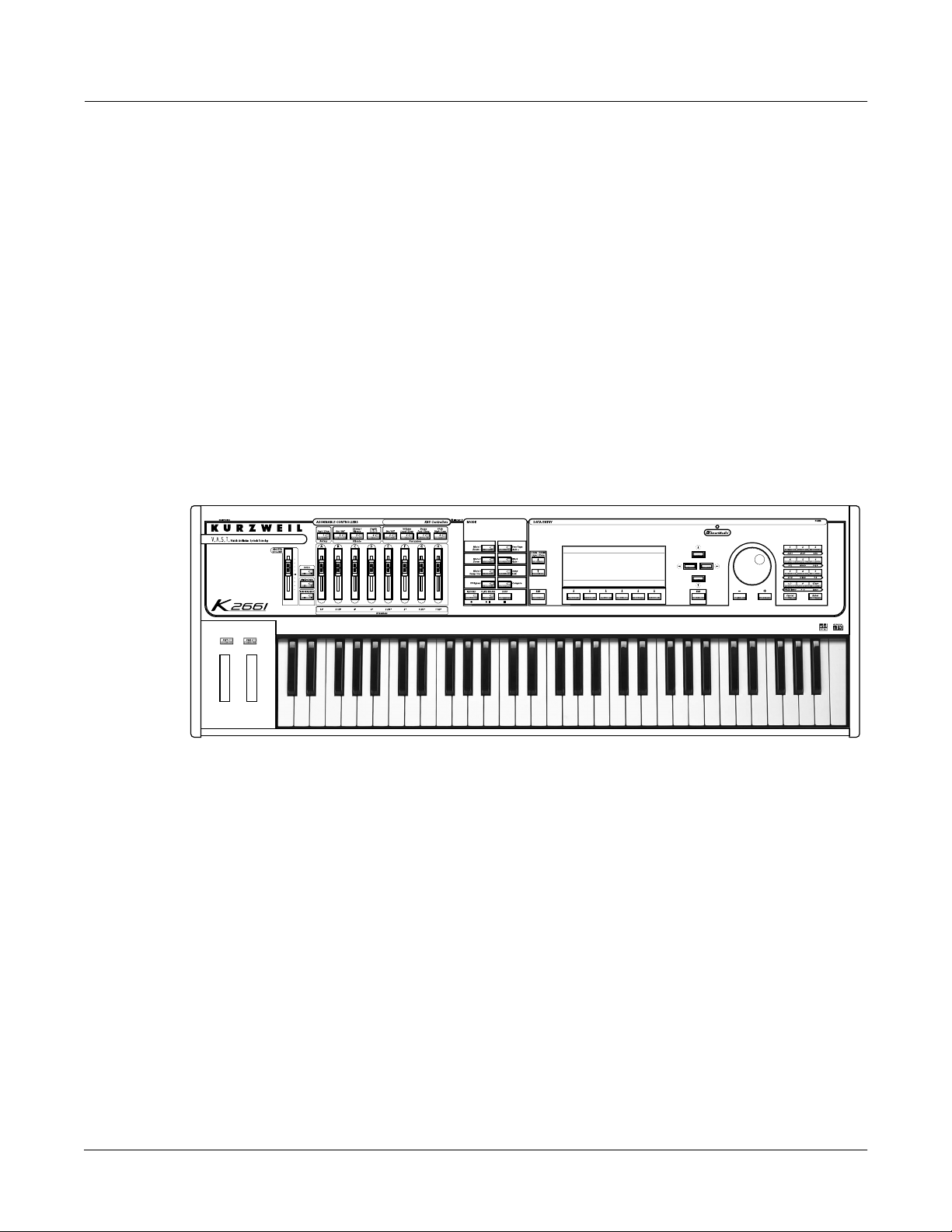
K 2661
Getting Started Guide
©2003 All rights reserved. Kurzweil ® is a product line of Young Chang Co., Ltd. Young Chang®, Kurzweil ® , V. A. S. T. ®, KDFX®,
Pitcher®, and LaserVerb®, KSP8 ™, K2661™, K2600™, K2500™, and K2000™ are trademarks of Young Chang Co., Ltd. SmartMedia™ is a
trademark of Toshiba Corporation. ADAT® is a registered trademark of Alesis Corporation. All other products and brand names are
trademarks or registered trademarks of their respective companies. Product features and specifications are subject to change without notice.
You may legally print up to two (2) copies of this document for personal use. Commercial use of any copies of this document
is prohibited. Young Chang Co. retains ownership of all intellectual property represented by this document.
Part Number: 910388 Rev. A
Page 2
CAUTION
RISK OF ELECTRIC SHOCK
DO NOT OPEN
CAUTION: TO REDUCE THE RISK OF ELECTRIC SHOCK,
DO NOT REMOVE THE COVER
NO USER SERVICEABLE PARTS INSIDE
REFER SERVICING TO QUALIFIED SERVICE PERSONNEL
The lightning flash with the arrowhead symbol,
within an equilateral triangle, is intended to alert
the user to the presence of uninsulated
"dangerous voltage" within the product's
enclosure that may be of sufficient magnitude
to constitute a risk of electric shock to persons.
The exclamation point within an equilateral
triangle is intended to alert the user to the
presence of important operating and
maintenance (servicing) instructions in the
literature accompanying the product.
IMPORTANT SAFETY & INSTALLATION INSTRUCTIONS
INSTRUCTIONS PERTAINING TO THE RISK OF FIRE, ELECTRIC SHOCK, OR INJURY TO PERSONS
WARNING: When using electric products, basic precautions should
always be followed, including the following:
1. Read all of the Safety and Installation Instructions and Explanation
of Graphic Symbols before using the product.
2. This product must be grounded. If it should malfunction or break
down, grounding provides a path of least resistance for electric
current to reduce the risk of electric shock. This product is equipped
with a power supply cord having an equipment-grounding
conductor and a grounding plug. The plug must be plugged into an
appropriate outlet which is properly installed and grounded in
accordance with all local codes and ordinances.
DANGER: Improper connection of the equipment-grounding
conductor can result in a risk of electric shock. Do not modify the
plug provided with the product - if it will not fit the outlet, have a
proper outlet installed by a qualified electrician. Do not use an
adaptor which defeats the function of the equipment-grounding
conductor. If you are in doubt as to whether the product is properly
grounded, check with a qualified serviceman or electrician.
3. WARNING: This product is equipped with an AC input voltage
selector. The voltage selector has been factory set for the mains
supply voltage in the country where this unit was sold. Changing
the voltage selector may require the use of a different power supply
cord or attachment plug, or both. To reduce the risk of fire or electric
shock, refer servicing to qualified maintenance personnel.
4. Do not use this product near water - for example, near a bathtub,
washbowl, kitchen sink, in a wet basement, or near a swimming
pool, or the like.
5. This product should only be used with a stand or cart that is
recommended by the manufacturer.
6. This product, either alone or in combination with an amplifier and
speakers or headphones, may be capable of producing sound
levels that could cause permanent hearing loss. Do not operate for
a long period of time at a high volume level or at a level that is
uncomfortable. If you experience any hearing loss or ringing in the
ears, you should consult an audiologist.
7. The product should be located so that its location or position does
not interfere with its proper ventilation.
8. The product should be located away from heat sources such as
radiators, heat registers, or other products that produce heat.
9. The product should be connected to a power supply only of the type
described in the operating instructions or as marked on the product.
10. This product may be equipped with a polarized line plug (one blade
wider than the other). This is a safety feature. If you are unable to
insert the plug into the outlet, contact an electrician to replace your
obsolete outlet. Do not defeat the safety purpose of the plug.
11. The power supply cord of the product should be unplugged from the
outlet when left unused for a long period of time. When unplugging
the power supply cord, do not pull on the cord, but grasp it by the
plug.
12. Care should be taken so that objects do not fall and liquids are not
spilled into the enclosure through openings.
13. The product should be serviced by qualified service personnel
when:
A. The power supply cord or the plug has been damaged;
B. Objects have fallen, or liquid has been spilled into the product;
C. The product has been exposed to rain;
D. The product does not appear to be operating normally or
exhibits a marked change in performance;
E. The product has been dropped, or the enclosure damaged.
14. Do not attempt to service the product beyond that described in the
user maintenance instructions. All other servicing should be
referred to qualified service personnel.
15. WARNING: Do not place objects on the product’s power supply
cord, or place the product in a position where anyone could trip
over, walk on, or roll anything over cords of any type. Do not allow
the product to rest on or be installed over cords of any type.
Improper installations of this type create the possibility of a fire
hazard and/or personal injury.
RADIO AND TELEVISION INTERFERENCE
WARNING: Changes or modifications to this instrument not expressly
approved by Young Chang could void your authority to operate the
instrument.
IMPORTANT: When connecting this product to accessories and/or other
equipment use only high quality shielded cables.
NOTE: This instrument has been tested and found to comply with the
limits for a Class B digital device, pursuant to Part 15 of the FCC Rules.
These limits are designed to provide reasonable protection against
harmful interference in a residential installation. This instrument
generates, uses, and can radiate radio frequency energy and, if not
installed and used in accordance with the instructions, may cause
harmful interference to radio communications. However, there is no
guarantee that interference will not occur in a particular installation. If
this instrument does cause harmful interference to radio or television
reception, which can be determined by turning the instrument off and on,
the user is encouraged to try to correct the interference by one or more
of the following measures:
SAVE THESE INSTRUCTIONS
ii
• Reorient or relocate the receiving antenna.
• Increase the separation between the instrument and the receiver.
• Connect the instrument into an outlet on a circuit other than the one
to which the receiver is connected.
• If necessary consult your dealer or an experienced radio/television
technician for additional suggestions.
NOTICE
This apparatus does not exceed the Class B limits for radio noise
emissions from digital apparatus set out in the Radio Interference
Regulations of the Canadian Department of Communications.
AVIS
Le present appareil numerique n’emet pas de bruits radioelectriques
depassant les limites applicables aux appareils numeriques de la
class B prescrites dans le Reglement sur le brouillage radioelectrique
edicte par le ministere des Communications du Canada.
Page 3

Important Safety Instructions
1) Read these instructions
2) Keep these instructions.
3) Heed all warnings.
4) Follow all instructions.
5) Do not use this apparatus near water.
6) Clean only with dry cloth.
7) Do not block any of the ventilation openings. Install in accordance with the manufacturer’s
instructions.
8) Do not install near any heat sources such as radiators, heat registers, stoves, or other apparatus (including amplifiers) that produce heat.
9) Do not defeat the safety purpose of the polarized or grounding-type plug. A polarized plug
has two blades with one wider than the other. A grounding type plug has two blades and a
third grounding prong. The wide blade or the third prong are provided for your safety. If the
provided plug does not fit into your outlet, consult an electrician for replacement of the obsolete outlet.
10) Protect the power cord from being walked on or pinched, particularly at plugs, convenience
receptacles, and the point where they exit from the apparatus.
11) Only use attachments/accessories specified by the manufacturer.
12) Use only with a cart, stand, tripod, bracket, or table specified by the manufacturer, or sold with the apparatus. When a cart is used, use caution when
moving the cart/apparatus combination to avoid injury from tip-over.
13) Unplug this apparatus during lightning storms or when unused for long
periods of time.
14) Refer all servicing to qualified service personnel. Servicing is required when the apparatus
has been damaged in any way, such as power-supply cord or plug is damaged, liquid has
been spilled or objects have fallen into the apparatus, the apparatus has been exposed to rain
or moisture, does not operate normally, or has been dropped.
Warning - To reduce the risk of fire or electric shock, do not expose this apparatus to rain or mois-
ture. Do not expose this equipment to dripping or splashing and ensure that no objects filled with
liquids, such as vases, are placed on the equipment.
To completely disconnect this equipment from the AC Mains, disconnect the power supply cord
plug from the AC receptacle.
iii
Page 4

Kurzweil International Contacts
Contact the nearest Kurzweil office listed below to locate your local Kurzweil representative.
Kurzweil Co., Ltd.
Daerung Technotown 6th, 306
493-6 Gasan, Gumcheon, Seoul, Korea
Tel: (+82) 2-2108-5700
Fax: (+82) 2-2108-5729
A N D Music Corp.
P.O. Box 99995
Lakewood, WA 98499-0995, USA
Tel: (253) 589-3200
Fax: (253) 984-0245
Young Chang Canada Corp.
250 Victoria Park Ave. Suite # 105
Toronto, Ontario Canada M2H 3P7
Tel: (905) 948-8052
Team Kurzweil Europe
Gl. Donsvej 8
6000 Kolding
Phone: (+45) 75 56 96 44
Fax: (+45) 75 56 96 55
Official distributors in other countries are listed on the web site.
World Wide Web Home Page:
http://www.kurzweilmusicsystems.com
iv
Page 5

Contents
Kurzweil International Contacts..................................................................................................................................... iv
World Wide Web Home Page: ......................................................................................................................................... iv
Chapter 1 Introduction
Overview of the K2661 ................................................................................................................................................... 1-1
VAST Synthesis................................................................................................................................................................ 1-2
KB3 Tone Wheel Emulation........................................................................................................................................... 1-2
How the K2661 Works .................................................................................................................................................... 1-3
How to Use This Manual ............................................................................................................................................... 1-3
Do I Have Everything? ................................................................................................................................................... 1-3
Chapter 2 Startup
Quick Startup Checklist ................................................................................................................................................. 2-1
Startup—the Details........................................................................................................................................................ 2-2
Playing the Presets .......................................................................................................................................................... 2-4
The Other Modes............................................................................................................................................................. 2-8
Software Upgrades.......................................................................................................................................................... 2-8
Chapter 3 User Interface Basics
Mode Selection................................................................................................................................................................. 3-1
Navigation........................................................................................................................................................................ 3-2
Data Entry ........................................................................................................................................................................ 3-4
Intuitive Data Entry ........................................................................................................................................................ 3-6
Search................................................................................................................................................................................ 3-7
Renaming Multiple Objects ........................................................................................................................................... 3-7
Mixdown and MIDI Faders Pages................................................................................................................................ 3-9
Quick Song Recording and Playback ......................................................................................................................... 3-10
Chapter 4 The Operating Modes
What the Modes Are....................................................................................................................................................... 4-1
Selecting Modes............................................................................................................................................................... 4-1
Using the Modes.............................................................................................................................................................. 4-3
Chapter 5 Editing Conventions
Introduction to Editing................................................................................................................................................... 5-1
Object Type and ID.......................................................................................................................................................... 5-2
Saving and Naming ........................................................................................................................................................ 5-3
Deleting Objects............................................................................................................................................................... 5-6
Memory Banks................................................................................................................................................................. 5-7
Special Button Functions................................................................................................................................................ 5-8
Chapter 6 Program Mode
VAST Program Structure................................................................................................................................................ 6-2
KB3 Program Structure................................................................................................................................................... 6-4
The Program Mode Page................................................................................................................................................ 6-9
Page 6

K2661 Getting Started Guide
Chapter 7 Setup Mode
Chapter 8 Quick Access Mode
Chapter 9 Basic Effects Mode
Introduction ..................................................................................................................................................................... 9-1
Terminology ..................................................................................................................................................................... 9-2
MAIN Page....................................................................................................................................................................... 9-5
Effects Bus Editor ............................................................................................................................................................ 9-7
Effects Send Page............................................................................................................................................................. 9-8
The CTRL Page ................................................................................................................................................................ 9-9
Bypass and Mute pages.................................................................................................................................................9-11
Chaining Effects............................................................................................................................................................. 9-13
The Structure of Kurzweil Digital Effects (KDFX) ................................................................................................... 9-14
Software Organization.................................................................................................................................................. 9-17
Controlling Effects......................................................................................................................................................... 9-17
Chapter 10 MIDI Mode
The TRANSMIT Page ................................................................................................................................................... 10-1
The RECEIVE Page ....................................................................................................................................................... 10-4
The Channels Page........................................................................................................................................................ 10-7
Program Change Formats ............................................................................................................................................ 10-9
The Soft Buttons in MIDI Mode ................................................................................................................................ 10-14
Chapter 11 Master Mode
The Master Mode Page..................................................................................................................................................11-1
The MAST2 Page............................................................................................................................................................11-4
The Soft Buttons in Master Mode ..............................................................................................................................11-11
Guitar/Wind Controller Mode...................................................................................................................................11-14
Object Utilities ..............................................................................................................................................................11-15
Chapter 12 Song Mode
Getting Started with the Sequencer............................................................................................................................ 12-1
Tutorial: Arrangements .............................................................................................................................................. 12-12
RAM Tracks.................................................................................................................................................................. 12-17
Using Song Mode........................................................................................................................................................ 12-19
Recording Multi-timbral Sequences via MIDI........................................................................................................ 12-23
Song Mode: The MAIN Page..................................................................................................................................... 12-24
Song Mode: The MISC Page ...................................................................................................................................... 12-32
Song Mode: The MIX Page ........................................................................................................................................ 12-39
Chapter 13 Basic Disk Mode
Disk Mode Page............................................................................................................................................................. 13-2
SCSI Termination........................................................................................................................................................... 13-3
Directories ...................................................................................................................................................................... 13-4
File List Dialog............................................................................................................................................................... 13-7
Creating Directories.....................................................................................................................................................13-11
vi
Page 7

K2661 Getting Started Guide
The Directory Selection Dialog.................................................................................................................................. 13-13
Disk Mode Functions.................................................................................................................................................. 13-14
Load Function Dialog ................................................................................................................................................. 13-19
Saving Files .................................................................................................................................................................. 13-24
Storing Objects in the Memory Banks...................................................................................................................... 13-34
The Multiple Object Selector Page............................................................................................................................ 13-34
Chapter 14 Sampling and Live Mode
Setting Up For Sampling.............................................................................................................................................. 14-1
Entering The Sampler ................................................................................................................................................... 14-1
Sampling Analog Signals ............................................................................................................................................. 14-2
Sampling the K2661’s Output...................................................................................................................................... 14-8
Sampling Digital Signals.............................................................................................................................................. 14-8
Live Mode..................................................................................................................................................................... 14-10
Chapter 15 Audio Outputs
Audio Configurations................................................................................................................................................... 15-1
Audio Routing: Programs to KDFX............................................................................................................................ 15-2
Audio Routing: KDFX to Audio Outputs.................................................................................................................. 15-2
Using the Digital Outputs............................................................................................................................................ 15-3
Appendix A K2661 Boot Block
Starting the Boot Block ..................................................................................................................................................A-1
Updating K2661 Software ............................................................................................................................................. A-1
Running Diagnostic Tests.............................................................................................................................................. A-3
Resetting the K2661........................................................................................................................................................ A-3
Appendix B Standard K2661 ROM Objects
Appendix C Contemporary ROM Block Objects
Programs...........................................................................................................................................................................C-2
Keymaps...........................................................................................................................................................................C-3
Program Control Assignments......................................................................................................................................C-4
Controller Assignments: Contemporary ROM Block................................................................................................C-7
Appendix D Orchestral ROM Block Objects
Programs.......................................................................................................................................................................... D-2
Keymaps.......................................................................................................................................................................... D-3
Program Control Assignments..................................................................................................................................... D-4
Controller Assignments: Orchestral ROM Block....................................................................................................... D-7
Appendix E General MIDI
General MIDI Programs................................................................................................................................................. E-2
Standard Mode Controller Assignments .....................................................................................................................E-3
vii
Page 8

K2661 Getting Started Guide
viii
Page 9
Chapter 1
Introduction
Thank you for purchasing a Kurzweil/Young Chang K2661 instrument.
The K2661 is packed with great acoustic, electric, and synth sounds—combined with some of
the most advanced synthesis features available, which you can use to create almost any sound
imaginable. The K2661 incorporates most of the features of the K2600, and provides several new
features as well.
This manual, along with the Musician’s Guide and Musician’s Reference (provided on the CDROM) will get you started with your new instrument. As you become an advanced user, you
will want to spend more time with the Musician’s Guide and Musician’s Reference to make the
most of your K2661’s many capabilities.
Introduction
Overview of the K2661
Overview of the K2661
The K2661 is a versatile performance instrument and an invaluable tool for multi-timbral
sequencing and recording. Its Variable Architecture Synthesis Technology (V.A.S.T.) lets you
build sounds from realistic instrumental samples and sampled synth waveforms—then modify
the nature of those sounds through a wide variety of digital signal-processing (DSP) functions.
The K2661 also generates its own synth waveforms, which can be combined with the samples or
used on their own. Onboard sound ROM includes the Orchestral and Contemporary sound
blocks, as well as a fine set of General MIDI (GM) sounds. You can add one or both of the two
available option ROMs (Stereo Dynamic Piano and Vintage Electric Pianos), and you can load
samples from disk into sample RAM.
Before we get into explaining VAST, here are a few of the features that by themselves make the
K2661 an impressive stage and studio machine. It’s fully multi-timbral—different programs can
be played on each MIDI channel. It’s 48-note polyphonic, for a full sound no matter how many
chords you play. There’s an on-board digital effects processor, providing up to five simultaneous
effects, including real-time effects control, internally or via MIDI.
In addition to the standard stereo audio output pair, there are four balanced analog outputs and
eight channel digital output.
1-1
Page 10

Introduction
VAST Synthesis
For sample memory, your K2661 has one SIMM (single, in-line memory module) installed in a
socket that you can reach through the access panel on the bottom of the instrument. If your
K2661 does not already have the maximum of 128 megabytes of Sample RAM installed, you can
install a larger SIMM using the instructions in the Musician’s Reference. The most important thing
for you to know about Sample RAM, however, is that it is not battery-backed; RAM samples are
permanently erased from memory when you power down. Fortunately, we’ve made offline
storage a snap.
There’s a SmartMedia slot for 3.3v SmartMedia cards, and also a SCSI port for connecting an
external hard disk or CD-ROM drive. You’ll find all this storage potential extremely useful for
saving and loading samples, which can also be transferred to and from the K2661 using the
standard MIDI sample transfer format, or the faster, parallel SMDI sample transfer format (SCSI
Musical Data Interchange). See the
sample transfers.
The K2661’s battery-backed program RAM can store hundreds of your own programs, or
thousands of notes recorded in the sequencer. This sequencer (Song mode) lets you play back
MIDI type 0 or 1 sequences, record and play back your own songs, and record multi-timbral
sequences received via MIDI. The battery should last for several years; instructions for replacing
it are in the Musician’s Reference (provided on CD-ROM).
Musician’s Reference for information about MIDI and SMDI
An optional sampling feature is available, allowing you to make your own mono or stereo
samples using analog or digital inputs. With the sampling option, you can also use Live mode,
which enables you to take an input signal and route it through the K2661’s VAST algorithms—so
you can apply Kurzweil DSP and effects to any sound.
There’s also digital input/output (I/O) in ADAT format, which provides eight channels for
digital audio input and output, as well as a stereo digital output in AES/EBU or S/PDIF
formats.
And, of course, there’s the incomparable Kurzweil sound. The K2661 comes to you with
hundreds of programs (called patches, presets, voices, etc. on other synths). There are also about
200 multi-zone performance setups. Many of these setups use note triggers to play factoryrecorded songs that provide grooves and arpeggiation that make great templates for
performance or recording.
VAST Synthesis
Variable Architecture Synthesis Technology gives the K2661 its unprecedented flexibility. While
many other synthesizers offer a fixed set of DSP tools (typically filtering, pitch, and amplitude
modulation) the K2661’s Variable Architecture lets you arrange a combination of any five DSP
functions from a long list of choices. The functions you choose define the type of synthesis you
use.
Each layer of every program has its own DSP architecture, which we call an algorithm . Within
each algorithm, you can select from a variety of DSP functions. Each function can be
independently controlled by a variety of sources including LFOs, ASRs, envelopes, a set of
unique programmable functions (FUNs), as well as any MIDI control message. The many
different DSP functions and the wealth of independent control sources give you an extremely
flexible, truly vast collection of tools for sound creation and modification. When you’re ready to
jump in and start creating programs, turn to Chapter 6.
KB3 Tone Wheel Emulation
In addition to VAST synthesis, the K2661 offers many oscillator-based programs that give you
the classic sound of tone-wheel organs like the Hammond B 3™. KB3 mode, as we call it, is
completely independent of VAST, and has its own set of editing procedures. You’ll find details in
Chapter 6.
1-2
Page 11

How the K2661 Works
The K2661 integrates three MIDI-driven components: a MIDI controller (the keyboard, or an
external MIDI controller, a sound engine, and a global effects processor (KDFX). The sound
engine responds to the MIDI events generated by the MIDI controller, and turns them into
sounds that are processed within the variable architecture of the algorithms—or by oscillators
for KB3 programs. The resulting sound can then be routed through KDFX and to the audio
outputs.
How to Use This Manual
This manual describes how to connect and power up your K2661, getting around the front
panel, and a brief description of the operating modes. For information on editing and advanced
programming features, refer to the Musician’s Guide and Musician’s Reference (provided on the
CD-ROM).
When manual text appears in boldface italic ( like this ), you’ll find it described in the Glossary in
the Musician’s Reference . Only the first one or two occurrences of these words are highlighted.
The Musician’s Reference also contains brief descriptions of the K2661’s major operating features,
and all sorts of useful lists— programs , keymaps , algorithms , effects, control sources , as well as
complete specifications for the K2661.
How the K2661 Works
Introduction
The best way to read this manual is with your K2661 in front of you. By trying the examples we
give to illustrate various functions, you can get a quick understanding of the basics, then move
on to the more advanced features.
Do I Have Everything?
Your K2661 shipping carton should include the following in addition to your instrument:
• Power cable
• Sustain pedal
• Getting Started manual
• SmartMedia card
• Compact disc with documentation and accessory files
• Warranty card
If you don’t have all of these components, please call your Kurzweil/Young Chang dealer.
The Accessory Files
The accessory files included with your K2661 (on SmartMedia and Compact Disc) include the
following. Additional files may be included; see the appropriate README files for these.
K2661 Base ROM Objects
These provide a backup of the ROM Objects installed in your K2661 at the factory.
You will not normally need to use these, however you should keep them in a safe place in case
you need to reinstall this version of the operating system. For example, if you have installed a
newer version of the objects (we make new versions available for download from our web site)
and you encounter any problems, you might need to go back and install the version on
SmartMedia and Compact Disc.
OBJKB contains all of the objects in a stock K2661 without sampling. OBJKL contains the Live
Mode objects, which are included in a unit with the sampling option installed.
1-3
Page 12

Introduction
Do I Have Everything?
When you install a new version of the operating system, you’ll need to load all the object files
for the options you have. This includes the object files for the SD Piano and Vintage Electric
Piano ROM blocks, if you have them. Load the system files first, then all of the object files, then
exit the Boot Loader by pressing the Run System soft button. See Appendix A if you need help
with operating the Boot Loader.
K2661 Demos
This includes several directories of demo song files, which show off some of the capabilities of
your K2661. In addition, KDFXTUTR.K26 contains objects used in the tour of Effects mode that
starts on page 9-22.
Most song demos can simply be loaded into the K2661 and played from Song mode. However,
two demo files require that your K2661 have the sampling option installed. The demo files
LMFBDMO1.K26 , and LMFBDMO2.K26 demonstrate internal feedback loops using a chain of
VAST->KDFX->sampler->VAST->KDFX—known as Live mode. Because a Master table is
included, your SampleMode settings will be set automatically when you load the demo file.
after loading these objects. Live-mode programs are inherently unstable when you’re in Live mode and the
sampling source (the Src parameter in the Samplemode page) is set to Int . These programs are capable of
producing tremendously loud feedback loops with a relatively small amount of gain. In modes where the
provided studio is not the active studio, the compressor that keeps these feedback chains under control isn’t
operating, and the loop can grow out of control very quickly. If you intend only to listen to the demo, and
not to examine the programming, we recommend that you delete the song file (and its dependent objects)
from your K2661 when you are done listening. We also recommend that you go to the SampleMode page
and set the Src parameter to Ext or the Mode parameter to something other than LiveIn , to help to avoid
any unintended feedback. If you want to look at the program settings, lower the volume on your
instrument, and read the more detailed description of Live mode beginning on page 14-41.
Caution : Programs that cause internal feedback can get extremely loud, so it’s important to be careful
K2661 Farm & Extras
This includes over 1000 extra programs and effects, all cultivated from the “farm” where we
grow our programs and effects.
The K2500FRM directory contains over 1000 extra programs, organized in files by type of
sound. This set of programs was originally developed for the K2500, hence the name.
The KDFXFARM directory contains two subdirectories. LIVEMODE contains a set of files
containing extra programs using Live mode (which requires having the sample option in your
K2500). MOREKDFX contains some FX Presets and a number of Programs that use KDFX, as
well as a couple of blank studios.
PIANOFRM contains extra programs that specifically use the 4-megabyte stereo piano.
VOCODER contains programs and setups that are designed to be used with the Vocoder
feature. You can read about the Vocoder in detail on page 11-4.
The MOREPRGS directory contains several files of extra programs.
K2600 / K2500 / K2000 Compatibility Files
These files includes of all the ROM objects in the original K2600, K2500, or K2000. You would
use one of the compatibility files if you have songs created for one of those older object sets. See
Loading Older Setup Versions on page 7-2 for information about using older objects with the
K2661.
1-4
Page 13

Chapter 2
Startup
If hooking up new gear is familiar to you, and you just want to get going, here’s a quick
description of all the basic things you need to cover to get started with your K2661. If you need
more information, thorough descriptions of each step follow. In either case, check out Playing the
Presets on page 2-4.
Quick Startup Checklist
1. Set the keyboard on a hard, flat, level surface. Make sure to leave plenty of room for
ventilation.
Startup
Quick Startup Checklist
2. Four adhesive-backed rubber feet are provided with your K2661. If you want to attach
them to the bottom of the K2661, carefully turn the keyboard over, remove the paper
backing from the rubber feet and attach them now. There are four pairs of holes on the
bottom of the keyboard – a pair in each corner – showing the best places to attach the
rubber feet.
3. Connect the power cable.
4. Make sure your sound system is at a safe volume level.
5. Plug in a pair of stereo headphones or run standard (1/4-inch) audio cables from your
amplifier or mixer to the MIX audio outputs on the K2661. (Use the MIX L out for mono.)
Start Jamming!
1. Power up your K2661 and check out some of the programs and setups. The K2661 starts
up in either Program mode or Setup mode—whichever of the two modes it was in when it
was last shut down (or given a soft reset). Press the button labeled Program or Setup to
switch modes.
2. If you hear distortion, reduce the gain on your mixing board, or use the pad if it has one.
3. Scroll through the program list with the Alpha Wheel.
4. Press the Quick Access mode button and use the alphanumeric buttons to select from
programmable banks of ten programs or setups.
5. If you don’t hear anything, review these steps, or check the Troubleshooting section in the
Musician’s Reference.
2-1
Page 14
Startup
Startup—the Details
Startup—the Details
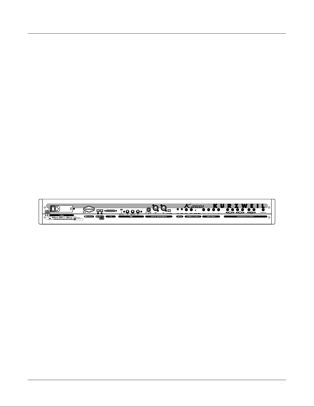
This section walks you through the hookup of your K2661. We’ll take a look at the rear panel,
then describe the power, audio, and other cable connections.
Before You Start...
Don’t connect anything until you make sure your K2661 is properly and safely situated. Also, if
your K2661 has been out in the cold, give it time to warm up to room temperature before
starting it, since condensation may have formed inside the K2661. Never block the ventilation
openings on the bottom or rear panels; doing so can cause overheating and serious damage. To
provide adequate ventilation, the rear panel should be at least four inches from any vertical
surface.
Connecting the Power Cable (Line Cord)
The K2661 runs on AC power: 100, 120, 230, or 240 volts at 50–60 Hz. Your dealer will set the
voltage switch to match the voltage in your area. The voltage level is set with a selector on the
rear panel of the K2661. Unless you are sure it needs to be changed, you shouldn’t adjust this.
When you’ve connected the cable at the K2661 end (as you face the back of the K2661, the power
connection is at the left), plug it into a grounded outlet. If your power source does not have the
standard three-hole outlet, you should take the time to install a proper grounding system. This
will reduce the risk of a shock.
2-2
Connecting the Audio Cables
After you’ve turned down the level on your sound system, connect the K2661’s analog audio
outputs to your sound system using a pair of stereo or mono audio cables. Mono cables will
always work, but if you’re going into balanced inputs, use stereo cables for a better signal-tonoise ratio. The K2661’s analog outputs are balanced, and generate a “hotter” signal than
previous Kurzweil instruments.
You’ll find six 1/4-inch jacks near the top of the rear panel. For now, connect one end of each
audio cable to your mixing board or PA system inputs, and connect the other end to the jacks
marked MIX L and R on the rear panel of the K2661. If you have only one input available, use
the K2661’s MIX L output to get the full signal in mono. You’ll find more about audio
configurations—including digital output—in Chapter 15.
Connecting MIDI
The simplest MIDI configuration uses a single MIDI cable: either from the MIDI Out port of
your K2661 to the MIDI In port of another instrument, or from the MIDI Out port of your MIDI
controller to the MIDI In port of the K2661. There are all sorts of possible configurations,
including additional synths, personal computers, MIDI effects processors, and MIDI patch bays.
Depending on your system, you may want to use the K2661’s MIDI Thru port to pass MIDI
information from a MIDI controller to the K2661 and on to the next device in your system. You
can also connect MIDI devices to the K2661’s MIDI Out port, which can send channelized MIDI
information from the keyboard or through the K2661 from your MIDI controller. See the
discussion of the Local Keyboard Channel parameter on page 10-6.
Page 15

Connecting SCSI
You may not have a hard disk or other SCSI device to connect to your K2661 right away, but if
you do, you can connect it to the SCSI port. Please read the following information carefully; it’s
very important. Also, there’s a collection of SCSI tips in Chapter 6 of the Musician’s Reference.
Note: SCSI on the K2661 is always terminated. Turn to Chapter 13 and read the section called SCSI
Termination if you require more information. You can lose data if your system isn’t terminated properly.
Switching On the Power
The power switch is on the rear panel. If you’re facing the keyboard, it’s just to the right of the
power cable connection.
When you power up, the display briefly show some startup information. The Program mode
display then appears. It looks like the diagram below (the programs shown in the diagram don’t
necessarily exist).
ProgramMode||||Xpose:0ST|||<>Channel:1||
!!!!!!!!!!!!!!!!!!@|998|James|Jams||||||
KeyMap|Info|||||||#|999|Default|Program|
|Grand|Piano||||||#|||1|Righteous|Piano|
||||||||||||||||||#|||2|Mondo|Bass||||||
||||||||||||||||||#|||3|Killer|Drums||||
%%%%%%^%%%%%%^%%%%$|||4|Weeping|Guitar||
Octav-|Octav+|Panic||Sample|Chan-||Chan+
Startup
Startup—the Details
The first time you power up (or after a reset), your instrument will be set to operate on MIDI
Channel 1 (as shown in the top line of the diagram). After that, it will power up on whatever
channel you were on when you powered down. If you’d rather have the K2661 reset certain
parameters to default values when you power up, you can do that, too. See Power
Mode on page 10-7.
Set the volume at a comfortable level. You’ll get the best signal-to-noise ratio if you keep the
K2661 at full volume, and adjust the level from your mixing board. You may also want to adjust
the display contrast and brightness. There are two small knobs on the rear panel of the K2661 for
this purpose.
SmartMedia
You can use 3.3v SmartMedia cards (4 megabyte and larger) for backing up, archiving, and
sharing your work. The SmartMedia card slot is on the back panel of the K2661, but it is easily
accessible from the front of the instrument. The gold contacts on the card must be facing up
when you insert it; the K2661 can’t read a card when it is inserted upside down.
Caution: Do not remove a SmartMedia card while the blue LED is lit. Removing a card while the blue
LED is lit can cause data corruption.
2-3
Page 16

Startup
Playing the Presets
Playing the Presets
There are three things you’ll want to check out right away: programs, setups and Quick Access
banks. In performance situations, you’ll be selecting your sounds using one of these three
methods. There’s a mode (and a mode button) corresponding to each method.
Getting Around
In all three of these modes, the bottom line of the display identifies the function of each of the
buttons beneath the display. We call these buttons soft buttons, because they do different things
depending on what’s currently showing in the display.
In Program and Quick Access modes, you can change MIDI channels with the Chan- and Chan+
buttons under the display. In Program mode, you can also change channels using the
Chan/Bank buttons to the left of the display. (In Quick Access mode, the Chan/Bank buttons
change Quick Access banks; more about that on page 2-7.) There are two more soft buttons that
appear in these modes: Panic and Sample.
The Panic button sends an All Notes Off message and an All Controllers Off message—both to
the K2661 and over all 16 MIDI channels. You won’t need it often, but it’s nice to have.
The Sample button takes you to Sample mode (the SampleMode page), which, as you’ve
probably guessed, is where you make your own samples—if you have the sampling option in
your instrument.
Programs
The K2661 powers up in Program mode, where you can select and play programs stored in
ROM or RAM. Programs are preset sounds composed of up to 32 layers of samples or
waveforms. If you’ve left Program mode, just press the Program mode button or Exit button to
return.
Take a minute to familiarize yourself with the Program-mode display. It gives you some helpful
basic information, like the MIDI transposition, what MIDI channel you’re on, and which
program is currently selected.
There’s a box at the left side of the display. The info box, as it’s called, displays information
about the current program (there’s also an info box for Setup mode). The following diagrams
shows how the information differs depending on the type of program you’ve selected.
VAST Programs
First is a “normal” VAST program, which is what most of the factory programs are. They have
from one to three layers. In this case, there are two. For programs of up to three layers, the info
box contains one line per layer, indicating the keymap used in that layer. The line under the
keymap name indicates the layer’s keyboard range. In this case, both layers extend across the
entire keyboard (A 0 to C 8).
ProgramMode||||Xpose:0ST|||<>Channel:1||
!!!!!!!!!!!!!!!!!@||||5|Piano|for|Layers
Keymap|Info||||||#||||6|DrkPno^ArakisPno
|Grand|Piano|||||#||||7|Honky-Tonk||||||
|Grand|Piano|||||#||||8|Pno&Syn/AcString
|||||||||||||||||#||||9|ClassicPiano&Vox
%%%%%%%%%%%%%%%%%$|||10|E|Grand|Stack|||
Octav-|Octav+|Panic||Sample|Chan-||Chan+
2-4
Page 17

Startup
Playing the Presets
VAST programs with more than three layers are known as drum programs, as shown in the
following diagram. Drum programs can use any sound you like, but the most common use for
programs with more than three layers is to create a number of different sounds across the
keyboard—which is perfect for combinations of percussion sounds (hence the name). For drum
programs, the info box simply indicates the number of layers in the program—in this case, 26.
ProgramMode||||Xpose:0ST|||<>Channel:1||
!!!!!!!!!!!!!!!!!!@||48|OG||||||||||||||
Drum|Program||||||#||49|Lowdown|Bass||||
26|layers|||||||||#||50|SquashStudio|Kit
||||||||||||||||||#||51|Retro|Skins|MW||
||||||||||||||||||#||52|2|Live|Kits|2|MW
%%%%%%^%%%%%%^%%%%$||53|Garage|Kit|II|MW
Octav-|Octav+|Panic||Sample|Chan-||Chan+
KB3 Programs
The architecture of KB3 programs is different from that of VAST programs. KB3 programs don’t
have layers; they rely on oscillators that mimic the tone wheels used in many popular organs.
Consequently, the info box shows only the waveform used in the program.
ProgramMode||||Xpose:0ST|||<>Channel:1||
!!!!!!!!!!!!!!!!!!@|751|Prog|Rock|Organ|
KB3|Program|||||||#|752|Syn|Rock|Organ||
|Mellow|Vox|||||||#|753|Dirty|Syn|B|||||
||||||||||||||||||#|754|CleanFullDrawbar
||||||||||||||||||#|755|Loungin|||||||||
%%%%%%^%%%%%%^%%%%$|756|MildGrunge||||||
Octav-|Octav+|Panic||Sample|Chan-||Chan+
Because of their architecture, KB3 programs require different processing within the K2661, and
they don’t work on “regular” channels. They require a special channel to handle the KB3
program’s voices. You can choose any of the 16 MIDI channels to be the KB3 channel, but you
can have only one KB3 channel, and KB3 programs play only on that channel (VAST programs
work just fine on the KB3 channel, by the way).
By default, Channel 1 is designated as the KB3 channel (you can change it in Master mode). If
the current channel isn’t the same as the KB3 channel, and you select a KB3 program, you won’t
get any sound, because a non-KB3 channel can’t handle a KB3 program.
2-5
Page 18

Startup
Playing the Presets
In the following diagram, Channel 2 is the current channel, but Channel 1 is the KB3 channel.
The info box tactfully lets you know what the KB3 channel is, and parentheses appear around
the names of all KB3 programs, to further remind you that KB3 programs aren’t available on the
current channel. To get Program 753 to work in this case, you’d have to change the current
channel back to Channel 1, or go to Master mode and change the KB3 channel to Channel 2.
ProgramMode||||Xpose:0ST|||<>Channel:2||
!!!!!!!!!!!!!!!!!!@|751|(Prog|Rock|Organ
KB3|Program|||||||#|752|(Syn|Rock|Organ)
|Mellow|Vox|||||||#|753|(Dirty|Syn|B)|||
||||||||||||||||||#|754|(CleanFullDrawba
KB3Chan|is|Ch|1|||#|755|(Loungin)|||||||
%%%%%%^%%%%%%^%%%%$|756|(Mild|Grunge)|||
Octav-|Octav+|Panic||Sample|Chan-||Chan+
Live Mode Programs
Programs 740–749 are designed expressly for Live mode, a feature that enables you to take a
signal from the Analog sampling input (this requires the sampling option, of course), and route
it through the DSP algorithms. Programs 740–749 will not play unless you’re receiving a signal
at the Analog sampling input. See page 14-10 for more about Live mode.
Setups
Selecting Programs
When you want to change programs, you have several options.
The easiest method is the Alpha Wheel. Turning it left or right will scroll through the program
list. You can also change programs using the cursor buttons (the arrow buttons to the right of the
display), or the Plus/Minus buttons under the Alpha Wheel. To save time, you can enter the
program number directly from the alphanumeric buttonpad to the right of the Alpha Wheel,
pressing the Enter button to complete the selection. If you make a mistake, press Clear, then
start over.
The K2661 has various settings for responding to MIDI Program Change commands from
external sources. These are explained in Chapter 10, so we won’t go into them here. You should
be able to change programs by sending Program Change commands from your MIDI controller.
If you don’t hear anything, see the troubleshooting section in the Musician’s Reference. When
you’re ready to start doing your own programming, check out Chapter 6.
Setups are preset combinations of programs. Setups can have up to eight zones, each of which
can be assigned to any range of the keyboard (overlapping or split). Each zone can have its own
program, MIDI channel, and MIDI control assignments.
Press the Setup mode button to the left of the display. Its LED will light, telling you that you’re
in Setup mode. Notice that the Setup-mode display is similar to the Program-mode display. If
the setup has three or fewer zones, the box at the left shows you the programs assigned to each
of the setup’s three zones, and which MIDI channel is used for each program. If the setup is
composed of more than three zones, then the box displays a series of horizontal lines illustrating
the approximate key ranges of the zones. See page 7-1 for a more detailed description.
2-6
Page 19

SetupMode||||||Xpose:0ST||||||||||||||||
!!!!!!!!!!!!!!!!!!@|201*Friday|Gig||||||
Chan/Program|Info|#|202*Bop|Rock|Reggae|
1||||9|Cool|Traps|#|||1|Jazz|Trio|||||||
2|||18|Sly|Acoust|#|||2|All|Percussion||
3|||22*Izit|Jimmy|#|||3|Heavy|Metal|||||
%%%%%%^%%%%%%^%%%%$|||4|To|Sequencer||||
Octav-|Octav+|Panic||Sample|||||||||||||
Many setups include arpeggiation and note-triggered songs to create some pretty amazing
grooves that you can use as is, or as templates for your own material. As you play with these
setups, experiment with the sliders and other controllers for a wide range of effects. Some of
these grooves keep playing after you’ve released the keys that got them going. When you want
to stop them, select another setup, or press the Setup mode button.
Quick Access
A really convenient way to select programs and setups is to use Quick Access mode, where you
select a Quick Access bank from a list of factory preset or user-programmed banks. Each bank
contains ten memory slots, or entries, where you can store any combination of programs or
setups. While you’re in Quick Access mode, you can select any program or setup in the bank
with buttons 0 through 9.
Startup
Playing the Presets
The K2661 comes with a few Quick Access banks already programmed so you can get an idea of
how they work. You’ll probably create your own Quick Access banks to help you select
programs and setups with a minimum of searching. Press the Quick Access mode button to the
left of the display. Its LED lights, to tell you you’re in Quick Access mode. You’ll see a display
that looks like this:
QuickAccessMode|||<>Bank:1|For|Show|1|||
Silk|Rhodes|||POLY|TOUCH||||Voice+String
NastyTrombone|SINK|MONSTA|||Waterflute||
Soon||||||||||Jazz|Trio|2|||Fretless|Bas
||||||||||||||VELVETEEN|||||||||||||||||
||||||||||||||||||||||||||||||||||||||||
|Xpose:0ST|||SINK|MONSTA||||||||Chan:1||
Octav-|Octav+|Panic||Sample|Chan-||Chan+
The top line of the display tells you which Quick Access bank is selected. Use the Chan/Bank
buttons (to the left of the display) to scroll through the banks. The names of each of the ten
entries in the bank are listed in the center of the display. Many of their names will be
abbreviated. The currently selected entry’s full name is shown near the bottom of the display.
The amount of transposition is displayed to the left of the entry name. If the current entry is a
program, you’ll see the current keyboard (MIDI) channel displayed to the right of the entry’s
name. If it’s a setup, you’ll see the word Setup.
The entries on the Quick Access page are arranged to correspond to the layout of the numeric
buttons on the alphanumeric pad. On the page above, for example, the program
SINK MONSTA is entry 5, and can be selected by pressing 5 on the alphanumeric pad.
When you’re ready to create your own Quick Access banks, turn to Chapter 8 to learn about the
Quick Access Editor.
2-7
Page 20

Startup
The Other Modes
The Other Modes
There are six other modes, five of which have mode buttons on the front panel (Sample mode
doesn’t have a front-panel button). See page 3-1 and Chapter 4 for more detailed descriptions of
each mode.
Effects mode Create and modify effects presets, and define how they’re applied to the
MIDI mode Configure the K2661 for sending and receiving MIDI information.
Master mode Define performance and control settings.
Song mode Record and edit sequences (songs); play Type 0 and Type 1 MIDI
Disk mode Load and save programs, setups, samples, and other objects.
Sample mode Edit ROM samples; create and edit RAM (user-defined) samples.
Software Upgrades
Part of the beauty of the K2661 is the ease with which you can upgrade its operating system and
objects (programs, setup, etc.) using the boot loader to install upgrades into flash ROM.
K2661’s programs and setups.
sequences.
At Kurzweil and Young Chang, we have a long history of support for our instruments; the K250,
K1000, K2000, and K2500 have been repeatedly enhanced, and these improvements have always
been made available to instrument owners in the form of software upgrades.
Upgrading your K2661’s software is simple, painless, and—generally—free! As upgraded
software becomes available, you can either get files from your Young Chang dealer or download
the new stuff from the Web.
To stay in touch, check out our Web site:
http://www.kurzweilmusicsystems.com/
When you’ve acquired an upgrade, you can install it yourself in a matter of minutes. See
Appendix A for details.
2-8
Page 21
Chapter 3
User Interface Basics
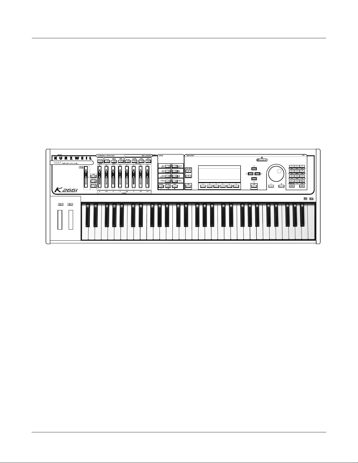
This chapter will show you how to get around the front panel of your K2661. Your interactions
can be divided into three primary operations: mode selection, navigation, and data entry. There
is also an assignable control section.
User Interface Basics
Mode Selection
Mode Selection
The K2661 is always in one of eight primary operating modes. Select a mode by pressing one of
the mode buttons — they’re to the left of the display. Each mode button has an LED that lights to
indicate the current mode. Only one mode can be selected at a time.
Program mode Select and play programs, and modify them with the Program Editor.
Setup mode Select and play setups (eight keyboard zones with independent MIDI
Quick Access mode Select from a list of preset banks, each containing a list of ten programs
Effects mode Define the behavior of the on-board effects. Modify the preset effects and
MIDI mode Define how your K2661 sends and receives MIDI information, and
Master mode Define performance and control characteristics for the entire K2661.
Rearrange and modify samples in the Keymap and Sample Editors.
channel, program and control assignments), and modify them with the
Setup Editor.
and/or setups that can be viewed in the display for easy selection.
Modify the preset banks and create your own with the Quick Access
Editor.
create your own with the Effects Editor.
configure each channel to receive independent program, volume, and pan
messages that override the normal Program-mode settings.
3-1
Page 22

User Interface Basics
Navigation
Song mode Use the K2661’s sequencer to record and play back your keyboard
Disk mode Interface with the K2661’s SmartMedia drive, or an external SCSI device
There are two more modes that don’t have dedicated buttons on the front panel: Sample mode
and Live mode. In Sample mode, you can create and edit samples (if you have the sampling
option). To get to Sample mode, press the Sample soft button in Program, Setup, Quick Access,
or Master modes. See Chapter 14 for details.
Live mode lets you route an input signal through the K2661’s DSP algorithms. See page 14-10.
Mode Buttons
The mode buttons are labeled in white. When you press a mode button, its LED lights up to
indicate that the mode has been selected. If pressing a mode button does not light its LED, press
the Exit button one or more times, then try again.
The colored labeling for each mode button indicates special functions that relate to some of the
K2661’s editors. These functions are described on page 5-8.
performance, play Type 0 and Type 1 MIDI sequences, and record multitimbral sequences received via MIDI.
to load and save programs, setups, samples, and more.
Navigation
The navigation section of the front panel consists of the display and the buttons surrounding it.
These navigation buttons will take you to every one of the K2661’s programming parameters.
The Display
Your primary interface with the K2661 is its backlit graphic display. As you press various
buttons, this fluorescent display reflects the commands you enter and the editing changes you
make. The ample size of the display (240-by-64 pixels) enables you to view lots of information at
one time.
Pages
Within each mode, the functions and parameters are organized into smaller, related groups that
appear together in the display. Each one of these groups of parameters is called a page. Each
mode has what we call an entry-level page; it’s the page that appears when you select that mode
with one of the mode buttons. Within each mode and its editor(s), the various pages are selected
with the navigation buttons. There are many pages, but there are a few features common to each
page. The diagram below shows the entry-level page for Program mode.
ProgramMode||||Xpose:0ST|||<>Channel:1||
!!!!!!!!!!!!!!!!!!@|200*Analog|Jam||||||
KeyMap|Info|||||||#|202*Heart|Strings|||
|Grand|Piano||||||#|||1|Righteous|Piano|
||||||||||||||||||#|||2|Mondo|Bass||||||
||||||||||||||||||#|||3|Killer|Drums||||
%%%%%%^%%%%%%^%%%%$|||4|Weeping|Guitar||
Octav-|Octav+|Panic||Sample|Chan-||Chan+
3-2
Page 23

The Top Line
On the top line of most pages, there’s a reminder of which mode you’re in and which page
you’re on. Many pages display additional information in the top line, as well. The
Program-mode page above, for example, shows you the current amount of MIDI transposition
and the currently selected MIDI channel. The top line is almost always “reversed”—that is, it
has a white background with blue characters.
The Bottom Line
The bottom line is divided into six (sometimes fewer) sets of reversed characters that serve as
labels for the six buttons directly beneath the display. These labels—and the functions of the
buttons—change depending on the currently selected page. Consequently the buttons that
select these functions are called “soft” buttons.
The Soft Buttons
The soft buttons are called “soft” because their functions change depending on the currently
selected mode. Sometimes they perform specific functions, like changing MIDI channels in
Program mode. In the Program Editor and other editors, they’re also used to move to different
pages of programming parameters. If a soft button’s label is in all capital letters (KEYMAP, for
example), pressing the corresponding soft button takes you to a page of parameters. If the soft
button is labeled in lower-case or mixed-case letters (Save, for example), the soft button
performs some kind of function.
User Interface Basics
Navigation
The Cursor Buttons
To the right of the display are four buttons arranged in a diamond fashion. These are called the
cursor buttons. They move the cursor around the currently selected page, in the direction
indicated by their labels. The cursor is a highlighted (reversed) rectangle (sometimes it’s an
underscore). It marks the value of the currently selected parameter.
Programming the K2661 involves selecting various parameters and changing their values. Select
parameters by highlighting their values with the cursor. You can change the highlighted value
with any of the data entry methods described in the data entry section below.
The Chan/bank Buttons
To the left of the display are two buttons labeled Chan/Bank. Their function is related to the two
small arrows—<|>—that appear in the top line of the display when there are multiples of the
current page—for example, the LAYER pages in the Program Editor. When you see these
arrows, you can use the Chan/Bank buttons to scroll the values of the parameter that appears to
the right of the arrows. In Program mode, for example, they shift through the MIDI channels,
showing the program assigned to each channel.
When you’re in the Program Editor, the Chan/Bank buttons let you view each layer in the
program. You can see the corresponding parameters in each layer by scrolling through the layers
with these buttons. In the Keymap Editor, Chan/Bank scroll through key ranges of the current
keymap. In the Setup Editor, the Chan/Bank buttons scroll through the zones in the current
setup. In Quick Access mode, they scroll through the Quick Access banks, and in Song mode
they scroll through recording tracks.
We’ll let you know, when applicable, what the Chan/Bank buttons do.
3-3
Page 24

User Interface Basics
Data Entry
The Edit Button
The Edit button activates each of the K2661’s editors, and acts as a shortcut to many pages
within the Program Editor. Pressing the Edit button tells the K2661 that you want to change
some aspect of the object marked by the cursor. For example, when a program is selected and
you press Edit, you enter the Program Editor. If a setup is selected, you enter the Setup Editor.
There are editors accessible from just about every operating mode. To enter an editor, choose one
of the modes (mode selection), and press Edit. An editing page for that mode will appear. You
can then select parameters (navigation) and change their values (data entry). If the value of the
selected parameter has its own editing page, pressing the Edit button will take you to that page.
For example, in the Program Editor, on the PITCH page, you might see LFO1 assigned as the
value for Pitch Control Source 1. If you select this parameter (the cursor will highlight its
value—LFO1 in this case), then press the Edit button, you’ll jump to the page where you can
edit the parameters of LFO1. Naturally, you can find every page in the current editor by using
the soft buttons, but often it’s easier to use the Edit button shortcut.
The Exit Button
Press Exit to leave the current editor. If you’ve changed the value of any parameter while in that
editor, the K2661 will ask you whether you want to save your changes before you can leave the
editor. See page 5-3 for information on saving and naming. The Exit button also takes you to
Program mode if you’re on the entry level page of one of the other modes. If at some point you
can’t seem to get where you want to go, press Exit one or more times to return to Program mode,
then try again.
Data Entry
The data entry section of the front panel includes the Alpha wheel, the Plus/Minus buttons, and
the 14-button alphanumeric pad.
The Alpha Wheel
The Alpha Wheel is especially useful because it can quickly enter large or small changes in
value. If you turn the Alpha Wheel one click to the right, you’ll increase the value of the
currently selected parameter by one increment. One click to the left decreases the value by one
increment. If you turn it rapidly, you’ll jump by several increments. You can also use the Alpha
Wheel to enter names when you’re saving objects.
The Plus/Minus Buttons
These buttons are located just under the Alpha Wheel. The Plus button increases the value of the
currently selected parameter by one, and the Minus button decreases it by one. These buttons
are most useful when you’re scrolling through a short list of values, or when you want to be sure
you’re changing the value by one increment at a time. One press of the Plus or Minus button
corresponds to one click to the right or left with the Alpha Wheel. These buttons will repeat if
pressed and held.
Pressing the Plus and Minus buttons simultaneously will move you through the current list of
values in large chunks instead of one by one. Often this is in even increments (10, 100, etc.).
Don’t confuse these buttons with the +/- button on the alphanumeric pad. This button is used
primarily for entering negative numeric values and switching from uppercase to lowercase
letters (and vice versa).
3-4
Page 25
The Alphanumeric Pad
As its name implies, this set of 14 buttons lets you enter numeric values, and to enter names one
character at a time. Depending on where you are, the K2661 automatically enters letters or
numerals as appropriate (you don’t have to select between alphabetic or numeric entry).
When you’re entering numeric values, press the corresponding numeric buttons, ignoring
decimal places if any (to enter 1.16, for example, press 1, 1, 6, Enter). The display will reflect
your entries, but the value won’t actually change until you press Enter. Before pressing Enter,
you can return to the original value by pressing Cancel. Pressing Clear is the same as pressing 0
without pressing Enter.
When entering names, you can use the Left/Right cursor buttons or the <<< / >>> soft
buttons to move the cursor to the character you want to change. Use the labels under the
alphanumeric buttons as a guide to character entry. Press the corresponding button one or more
times to insert the desired character above the cursor. The Cancel button is equivalent to the
>>> soft button, and Enter is the same as OK. The Clear button replaces the currently selected
character with a space. The +/- button toggles between uppercase and lowercase letters.
There’s also a convenient feature called keyboard naming, which lets you use the keyboard to
enter characters in names. See page 5-5.
Double Button Presses
Pressing two or more related buttons simultaneously executes a number of special functions
depending on the currently selected mode. Make sure to press them at exactly the same time.
User Interface Basics
Data Entry
In this
mode or
editor…
Program
mode
Master mode Chan/Bank Enables Guitar/Wind Controller mode.
Song mode
Disk mode
Program
Editor
…pressing these buttons
simultaneously…
Octav-, Octav+ Reset MIDI transposition to 0 semitones. Double-press again to
go to previous transposition.
Chan–, Chan+ Set current MIDI channel to 1.
Plus/Minus Step to next Program bank (100, 200, etc.)
Left/Right cursor buttons Toggle between Play and Stop.
Up/Down cursor buttons Toggle between Play and Pause.
Chan/Bank Select all tracks on any TRACK page in Song Editor.
2 leftmost soft buttons Issue SCSI Eject command to currently selected SCSI device.
Chan/Bank Hard format SCSI device. List selected objects when saving
objects.
Left/Right cursor buttons Select all items in a list. Move cursor to end of name in naming
dialog.
up/down cursor buttons Clear all selections in a list. Move cursor to beginning of name
in naming dialog.
Chan/Bank Select Layer 1.
…does this:
Table 3-1 Double Button Presses
3-5
Page 26
User Interface Basics
Intuitive Data Entry
In this
mode or
editor…
Keymap
Editor
Sample
Editor
Any Editor
Save Dialog Plus/Minus buttons Toggle between next free ID and original ID.
…pressing these buttons
simultaneously…
Plus/Minus With cursor on the Coarse Tune parameter, toggles between
default Coarse Tune of sample root and transposition of sample
root.
2 leftmost soft buttons Toggle between default zoom setting and current zoom setting.
Plus/Minus buttons Set the value of the currently selected parameter at the next
zero crossing.
Plus/Minus Scroll through the currently selected parameter’s list of values in
regular or logical increments (varies with each parameter).
2 leftmost soft buttons Reset MIDI transposition to 0 semitones. Double-press again to
go to previous transposition.
Center soft buttons Select Utilities menu (MIDIScope, Stealer, etc.).
2 rightmost soft buttons Sends all notes/controllers off message on all 16 channels
(same as Panic soft button).
Left/Right cursor buttons Toggle between Play and Stop of current song.
Up/Down cursor buttons Toggle between Play and Pause of current song.
…does this:
Table 3-1 Double Button Presses
Intuitive Data Entry
Many parameters have values that correspond to standard physical controllers. In many cases,
you can select these values “intuitively,” rather than having to scroll through the Control Source
list. This is done by selecting the desired parameter, then holding the ENTER button while
moving the desired physical control.
For example, on the LAYER page in the Program Editor, you can set the range of the currently
selected layer as follows: use the cursor buttons to move the cursor to the value for the LoKey
parameter, press (and hold) the Enter button, then press the note you wish to be the lowest note
for the currently displayed layer. The note you triggered (it has to be between C 0—C 8) will
appear as the value for the LoKey parameter. Repeat the process for the HiKey parameter.
Another example: select Program 199 while in Program mode. Press Edit to enter the Program
Editor. Press the PITCH soft button to select the PITCH page. Move the cursor to the Src1
parameter. Hold the Enter button, and move the Pitch Wheel. PWheel will be selected as the
value for Src1.
You can also use the keyboard to choose control sources, since most key numbers correspond to
a value on the control source list. If you have a certain control source that you use over and over
(for example, LFO1), this can be the quickest way to enter its value. To do this: highlight a
parameter which uses a value from the control source list, hold down Enter, then strike the key
corresponding to the control source you want to choose. LFO1, for example, is assigned to B5.
You’ll find a complete chart of these keyboard shortcuts at the end of Chapter 4 of the Musician’s
Reference.
Also, for almost every parameter, you can hold the Enter button and move the Data Slider to run
through the range of values for the currently selected parameter. This is not as precise as the
Alpha Wheel, but much faster.
3-6
Page 27

Changing the Current Layer in Multi-Layer Programs
Search
User Interface Basics
Search
When editing a multi-layer program (including drum programs), you can quickly switch
between layers by holding the Enter button, then striking a key. The K2661 will change the
current layer to that key’s layer. If the key is part of more than one layer, subsequent key strikes
will cycle through each layer that has that key in its range.
Note: This method for changing the current layer in a multi-layer program will NOT work if the
currently highlighted parameter has a note number or control source for its value. In this case, the key you
strike will function as described in Intuitive Data Entry, above.
There’s a convenient way to find any string of characters within the currently selected list, or
range of values. Hold the Enter button and press any of the numeric buttons. A dialog like the
one below appears.
|||||||||||||||||||||||||<>KbdNaming:Off
||||||||||||||||||||||||||||||||||||||||
||||||||||||||||||||||||||||||||||||||||
Search|string:||Soul|Rebels|||||||||||||
||||||||||||||||||||||||||||||||||||||||
||||||||||||||||||||||||||||||||||||||||
||||||||||||||||||||||||||||||||||||||||
Delete|Insert||<<<||||>>>||||OK|||Cancel
Type in the string of characters you want to find. For example, if you’re looking at the program
list and you want to find all programs containing the word “Horn,” you would type h-o-r-n.
This function is not case-sensitive; it will find upper and lower case characters regardless of
what you type.
When you’ve typed the string of characters you want to find, press Enter. The K2661 searches
through the current list of objects or values, finds all items that match the string of characters
you typed, and displays the first one it finds. Hold Enter and press one of the Plus/Minus
buttons to search for the next higher- or lower-numbered object that contains the string of
characters.
The string you select remains in memory. You can store and select a string of characters with
each of the numeric buttons. Hold Enter and press one of the numeric buttons at any time to
select that string for a search. When the string appears, you can change it, or just press Enter to
find that string.
Renaming Multiple Objects
You can automatically rename multiple RAM objects with one operation, by substituting one
string of characters with another.
1. Press the Master mode button to enter Master mode.
2. Press the Object soft button, then press the Name soft button. The NAME page appears,
showing a list of all RAM objects.
3-7
Page 28

User Interface Basics
Renaming Multiple Objects
3. Use the Alpha Wheel or Plus/Minus buttons to highlight objects. When an object whose
4. When you’ve selected all the objects you want to rename, press OK. The following dialog
5. Use your favorite method to enter a slash (/), followed by the string of characters that you
name you want to change is highlighted, press the Select soft button to select the object.
Note the asterisk that appears between the object’s ID and its name.
appears. The name you see is the name of the last object you selected.
|||||||||||||||||||||||||<>KbdNaming:Off
||||||||||||||||||||||||||||||||||||||||
||||||||||||||||||||||||||||||||||||||||
Object|Name:||||Badname|||||||||||||||||
||||||||||||||||||||||||||||||||||||||||
||||||||||||||||||||||||||||||||||||||||
||||||||||||||||||||||||||||||||||||||||
Delete|Insert||<<<||||>>>||||OK|||Cancel
want to replace. This function is case-sensitive, so you can enter both capitals and lowercase characters. In this example, we’re going to change “Bad” to “Good.”
|||||||||||||||||||||||||<>KbdNaming:Off
||||||||||||||||||||||||||||||||||||||||
||||||||||||||||||||||||||||||||||||||||
Object|Name:||||/Bad||||||||||||||||||||
||||||||||||||||||||||||||||||||||||||||
||||||||||||||||||||||||||||||||||||||||
||||||||||||||||||||||||||||||||||||||||
Delete|Insert||<<<||||>>>||||OK|||Cancel
6. When you’ve entered the desired string of characters, press OK, and the dialog changes to
prompt you to enter the replacement string. Notice that we entered only the characters
B-a-d, and not the entire name of the object. Enter the new string, as shown below.
|||||||||||||||||||||||||<>KbdNaming:Off
||||||||||||||||||||||||||||||||||||||||
||||||||||||||||||||||||||||||||||||||||
Replace|with:|||Good||||||||||||||||||||
||||||||||||||||||||||||||||||||||||||||
||||||||||||||||||||||||||||||||||||||||
||||||||||||||||||||||||||||||||||||||||
Delete|Insert||<<<||||>>>||||OK|||Cancel
7. Press OK. The K2661 asks you if you’re sure (unless you have confirmations turned off).
Press Yes. The NAME page reappears. Every RAM object whose name contained Bad now
contains Good instead.
3-8
Page 29
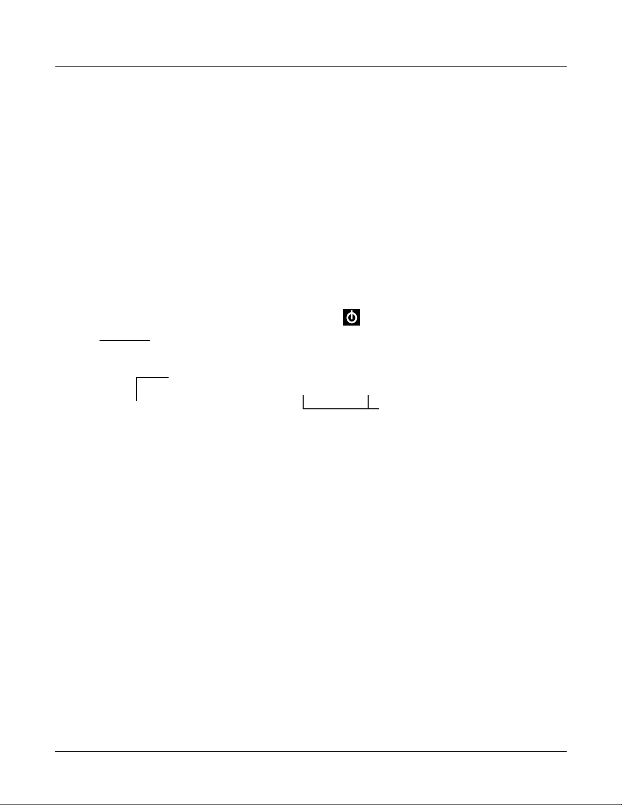
Mixdown and MIDI Faders Pages
There are two buttons below the Solo button, labeled Mixdown and MIDI Faders. These call up
pages that let you use the sliders to control MIDI Pan and Volume, or any MIDI Controller that
you choose. This is useful for real-time control over setups.
Mixdown Page
This page temporarily turns the K2661’s 8 sliders into MIDI pan and volume controls. You can
get to this page from any mode by pressing the Mixdown button, located below the Solo button.
Press Mixdown, and the display looks similar to what you see on the Song-mode MIX page.
However, there are a few differences. On the Mixdown page, the sliders relate to MIDI channels
instead of tracks. If you highlight 1-8 for example, moving slider D will affect volume or pan for
MIDI Channel 4 while you’re on this page.
User Interface Basics
Mixdown and MIDI Faders Pages
>> shows
whether sliders
control pan or
volume
Mixdown||||<>Prog:|36|DuckWalk||||||||||
|||WXWXWXWX|WXWXWXWX|WXWXWXWX|WXWXWXWX||
|||wxwxC{wx|wxwxwxwx|wxwxwxwx|wxwxwxwx||
>>||z|z}~|z||z|z|z|z||z|z|z|z||z|z|z|z||
||||_|_|_|_||_|_|_|_||_|_|_|_||_|_|_|_||
||||||||||||||||||||||||||||||||||||||||
|||*****************||||||||||||||||||||
|Pan|||Volume|Ch|1-8|Ch9-16|||||||||Done
Shows which channels are
affected by sliders.
On the Mixdown page, pan and volume messages are sent to the internal K2661 sounds, to MIDI
Out, or both. All Mixdown-page channels have the same destination (local, MIDI, or both),
which is determined by the Control parameter on the MIDI-mode TRANSMIT page. You can
assign the sliders to control either volume or pan. The soft buttons at the bottom of the
Mixdown page let you select pan or volume control, on channels 1-8 or 9-16, allowing you to
temporarily use the 8 sliders as pan or volume faders. Keep in mind that MIDI volume is a
channel-specific message. Therefore, if you have more than one zone in a setup assigned to the
same channel, moving any one of the associated sliders will affect all those zones.
MIDI Faders Pages
The button just below Mixdown is called MIDI Faders. The MIDI Faders page allows you to
create a preset configuration of any Controller assignment for each slider, along with an initial
preset value for that Controller. For each slider, you assign the MIDI channel, MIDI Controller
number, and a value. You can enter the value using any normal data entry method, or by
moving the corresponding slider on keyboard models. You can also assign several sliders to the
same channel, but assign each one to a different Controller number.
Soft buttons for indicating
which channels are
affected by sliders.
There are four different configurations (pages 1–4), which you select with the soft buttons. Each
configuration remembers the last value you set for each slider. If you want to send those values
without moving the slider, press the Send button.
3-9
Page 30

User Interface Basics
Quick Song Recording and Playback
The available values for the Channel parameter on this page are 1–16 (local and MIDI), 1L–16L
(local only, no MIDI), and 1M–16M (MIDI only, no local).
MIDI|Faders:Page1|||||||||||||||||||||||
Chan|:|9|||10||11||12||13||14||15||16|||
Ctl||:|6|||6|||6|||6|||6|||6|||6|||6||||
Value:|50||0|||50||0|||50||0|||50||0||||
||||||||||||||||||||||||||||||||||||||||
||||||\]||}~||\]||}~||\]||}~||\]||}~||||
|||||||_|||_|||_|||_|||_|||_|||_|||_||||
Page1||Page2||Page3||Page4|||Send||Done|
Quick Song Recording and Playback
There are three buttons—labeled Record, Play/Pause, and Stop—below the mode selection
buttons. They control the recording and playback of songs from any mode; you don’t have to be
in Song mode to record or play back.
Using these buttons affects the current track of the current song—that is, the song and track that
were selected the last time you were in Song mode. When you record, the recording track and
recording mode are determined by the current settings in Song mode; likewise for the playback
mode when you’re playing a song.
When the sequencer status is STOPPED (neither the Record-button LED nor the Play/Pausebutton LED is lit or flashing), press Record to put the sequencer in REC READY status. The
Record-button LED lights (red). Then press Play/Pause to start recording. The Play/Pausebutton flashes (green) to indicate the tempo. Any countoff is determined by the current Songmode setting for the CountOff parameter. Press Play/Pause or Stop to end recording and go to
the Save dialog, where you can save the song, or trash it.
When the sequencer status is STOPPED, press Play/Pause to begin playing the current song.
Press Play/Pause again to pause playback, and again to resume. Press Stop to end playback.
3-10
Page 31

Chapter 4
The Operating Modes
In this chapter we’ll discuss the theory behind the mode concept, and we’ll describe the basic
operating features of each mode. Complete details on the editing features of each mode are
provided in the K2661 Musician’s Guide (on the CD-ROM).
What the Modes Are
The modes exist to make the K2661 logical to work with. With as many performance and
programming features as the K2661 has, it’s helpful to break them into groups. These groups are
called modes. There are eight primary modes (plus Sample mode and Live mode); they’re
described briefly in the section called Using the Modes on page 4-3. Chapters 6 through 13 are
dedicated to explaining each primary mode in turn. Chapter 14 describes Sample mode and
Live mode.
Each mode is named for the kind of operations you perform while in that mode, and each
mode’s editor (if any) contains all of the parameters related to editing the type of object found in
that mode. In Setup mode, for example, you select setups (and only setups) for performance or
editing. All of the setup-editing parameters are grouped together on the Setup-Editor page,
which is accessible through Setup mode.
The Operating Modes
What the Modes Are
Selecting Modes
When the K2661 is on, it’s almost always operating in one of the eight primary modes
represented by the LED-highlighted buttons beneath the display—or in one of the editors
corresponding to the current operating mode. There are two exceptions: Sample mode (and the
Sample Editor), and Live mode. Pressing one of the mode buttons selects the corresponding
mode. This is the mode’s entry level. At the entry level, the LED of the selected mode is lit. Only
one mode can be selected at a time.
From any primary mode, you can get to any other primary mode simply by pressing one of the
mode buttons. If you’re in an editor, however, you must press Exit to return to the mode’s entry
level before selecting another mode.
All of the modes except Disk mode and Live mode give you access to one or more editors for
changing the values of the parameters within that mode. Press the Edit button to enter the editor
of the currently selected mode. When you do this, the mode LED goes out.
It’s possible to enter another mode’s editor without leaving the currently selected mode. For
example, if you press Edit while in Setup mode, you’ll enter the Setup Editor. The Setup-Editor
page will appear, and the LocalPrg parameter will be highlighted by the cursor. If you press Edit
again, you’ll enter the Program Editor, where you can edit the currently selected program. While
you can edit and save programs as you normally would, you’re still in Setup mode, and you
can’t select another mode at this point. When you exit the Program Editor, you’ll return to the
Setup-Editor page. Press Exit again, and you’ll leave the Setup Editor, returning to the
Setup-mode page.
This method of entering editors works for any parameter whose value is an editable object
(program, setup, keymap, FX preset, etc.)
4-1
Page 32

The Operating Modes
Selecting Modes
The following table lists the procedures for moving between modes and editors. Note that the
Exit button won’t always take you where the table says it will; it often depends on how you got
where you are. The table assumes that you’ve entered a given editor via its corresponding mode.
You’ll always return to Program mode eventually if you press Exit repeatedly.
Current Mode/
Editor Status
Any mode All other modes Press corresponding mode button
Program mode
Program Editor
Keymap Editor
Sample Editor Keymap Editor Press Exit
Setup mode
Setup Editor
Quick Access mode
Quick Access Editor
Effects mode Studio Editor Press Edit
Studio Editor
FX Preset Editor Studio Editor Press Exit
MIDI mode
Master mode
Song mode
Sample mode
Most editors Previous mode or editor Press Exit
Available Modes/
Editors
Program Editor Press Edit
Sample mode Press Sample soft button
Program mode Press Exit
Studio Editor On KDFX page: select Studio parameter; press Edit
Keymap Editor On KEYMAP page: select Keymap parameter, press Edit
Program Editor Press Exit
Sample mode Press the MIDI mode button
Sample Editor Select Sample parameter; press Edit
Sample mode Press Sample soft button
Setup Editor Press Edit
Setup mode Press Exit
Program Editor On CH/PRG page: select LocalPrg parameter; press Edit
Studio Editor On KDFX page: select Studio parameter; press Edit
Song Editor On COMMON page, select Song parameter; press Edit
Sample mode Press Sample soft button
Quick Access Editor Press Edit
Quick Access mode Press Exit
Program Editor Set value of Type parameter to Program; select program; press Edit
Setup Editor Set value of Type parameter to Setup; select setup; press Edit
Previous mode Press Exit
FX Preset Editor Select FX preset block; press Edit
Program Editor On CHANNELS page: select Program parameter; press Edit
Setup Editor On TRANSMIT page: select CtlSetup parameter; press Edit
Velocity Map Editor On TRANSMIT or RECEIVE page: select Veloc(ity)Map parameter; press Edit
Pressure Map Editor On TRANSMIT or RECEIVE page: select Press(ure)Map parameter; press Edit
Sample mode Press Sample soft button
Velocity Map Editor Select VelTouch parameter; press Edit
Pressure Map Editor Select PressTouch parameter; press Edit
Intonation Table Editor Select Intonation parameter; press Edit
Song Editor Select CurSong parameter; press Edit
Program Editor Select Program parameter; press Edit
Sample Editor Select Sample parameter; press Edit
Previous mode Press Exit
How to Get There
4-2
Page 33

Nested Editors
Starting at the Program-mode level, there are three “nested” editors, each related to the
parameters that make up different components of a program. The first is the Program Editor,
which you enter when you press Edit while in Program mode. Programs consist, among other
things, of keymaps; they determine which samples play on which keys. Keymaps can be edited
as well. The Keymap Editor is entered from within the Program Editor, by selecting the
KEYMAP page with the soft buttons, then pressing Edit.
Similarly, keymaps consist of samples, which also can be edited. The Sample Editor is entered
from the Keymap Editor, by selecting the Sample parameter and pressing Edit. When you enter
the Sample Editor, you’ve worked through three nested levels of editors, all related to the
components that make up a program. And in fact, you’re still in Program mode (if that’s where
you started from). Pressing Exit while in the Sample Editor will return you to the Keymap
Editor. Pressing Exit again will return you to the KEYMAP page of the Program Editor. Once
more, and you’re back to Program mode’s entry level.
Note: You can also get to the Sample Editor directly from Sample mode (by pressing Edit). If you’re
editing a single sample, this might make more sense, since it’s more direct. If you’re planning on editing a
number of samples within a given keymap, however, you’ll find it more convenient to enter the Sample
Editor through the Program and Keymap Editors, because once you’ve finished with one sample, you can
easily return to the KEYMAP page and select another sample within the keymap.
The Operating Modes
Using the Modes
Finding Square One
If, at any time, you don’t know where you are, and the mode LEDs are all unlit, press Exit one or
more times. This will return you to the entry level of whatever mode you were in, and if you
press Exit enough times, you will always return to Program mode, the startup mode. If you’ve
made any changes, you’ll be asked whether you want to save before leaving any editor. Press
the No soft button or the Exit button if you don’t want to save. If you want to save, press the
Rename or Yes soft button, and you’ll see the Save dialog, which is described in Saving and
Naming on page 5-3.
Using the Modes
You can play your K2661 regardless of the mode you’re in. In fact, the only times you can’t play
it are when you’re in the middle of a disk operation (loading, saving, formatting) or a SMDI
sample transfer. With these two exceptions, the K2661’s MIDI response is almost always active.
Even so there are three modes that are more performance-oriented than the others. These are
Program, Setup, and Quick Access modes. We’ll describe each of the eight modes briefly in this
section.
Program Mode
The K2661 starts up in Program mode, where you can select, play, and edit programs. The
Program-mode entry-level page shows the currently selected program, as well as a small
segment of the program list. Program mode gives you access to Sample mode via the Sample
soft button.
The Program, Keymap, and Sample Editors are nested within Program mode. They take you to
the core of the K2661’s sound editing parameters. See the K2661 Musician’s Guide (on the CD-
ROM) for details.
Setup Mode
Setup mode lets you select, play, and edit setups. Setups consist of up to eight separate zones,
split or overlapping, each having its own program, MIDI channel, and control parameters.
Setups are great for performance situations, whether you’re playing multiple K2661 programs
4-3
Page 34

The Operating Modes
Using the Modes
or controlling additional synths connected to the K2661’s MIDI Out port. Chapter 7 describes
Setup mode .
If you’re using a different MIDI controller, you can make use of Setup mode even if your MIDI
controller can transmit on only one MIDI channel at a time. To do this, go to the RECEIVE page
in MIDI mode (by pressing the RECV soft button while in MIDI mode), and set the Local
Keyboard Channel parameter to a value that matches the transmit channel of your MIDI
controller. When you select Setup mode, the K2661 will interpret incoming MIDI information
according to the settings for the currently selected setup. See the discussion of the Local
Keyboard Channel parameter in Chapter 10 for details.
Setup mode also gives you access to Sample mode via the Sample soft button.
Quick Access Mode
Another feature for live performance, Quick Access mode enables you to combine programs and
setups into banks of ten entries. Each of these programs or setups can be selected with a single
alphanumeric button. Different banks are selected with the Chan/Bank buttons. There’s a
selection of factory preset banks, and you can use the Quick Access Editor to create your own
banks and store them in RAM. There’s a full description in Chapter 8.
Quick Access mode gives you access to Sample mode via the Sample soft button. You can also
use Quick Access banks as a way to remap incoming or outgoing Program Change commands.
Effects Mode
Effects mode sets the behavior of the KDFX effects processor. The Effects-mode page lets you tell
the K2661 how to select preset studios (programmed effects configurations) when you change
programs or setups, or lets you choose a preset studio that’s applied to every K2661 program.
The Studio Editor allows you to tweak the preset studios, and create your own. Chapters 9
shows you how. You can also listen to the sounds of various effects while in Effects mode,
without selecting different programs.
MIDI Mode
You’ll use MIDI mode to configure the K2661’s interaction with other MIDI instruments, by
setting parameters for transmitting and receiving MIDI. You’ll also use it to configure your
K2661 for multi-timbral sequencing. On the CHANNELS page, you can assign a program to
each channel, and enable or disable each channel’s response to three types of MIDI control
messages: Program Change, volume and pan. You can also override program output
assignments, and adjust overall program gain. See Chapter 10.
Master Mode
Master mode, described in Chapter 11, contains the parameters that control the entire K2661.
Global settings for tuning, transposition, velocity and aftertouch sensitivity, and other
preferences are adjusted here. You can also get to GM Mode and SampleMode from here.
Song Mode
Song mode enables you to play sequences (songs) stored in the K2661’s RAM, and provides a
fully featured sequencer that you can use to record songs. You can also record multi-timbrally
via MIDI, or load standard MIDI files (Type 0 or 1). The Song Editor enables you to modify
existing RAM sequences, do step recording, and create arrangements (by linking two or more
songs together). See Chapter 12.
4-4
Disk Mode
Disk mode lets you load and save programs and other objects using the K2661’s SmartMedia
drive or a disk (or CD-ROM drive) connected to the K2661’s SCSI port. See Chapter 13.
Page 35

Chapter 5
Editing Conventions
Introduction to Editing
Programming (editing) the K2661 always involves three basic operations: mode selection,
navigation, and data entry.
First, select the mode that relates to the object you want to edit—a program, a setup, etc. Then
select the object you want to edit, and press the Edit button to enter the editor within that mode.
An editor contains all the parameters that define the object you’re programming.
Next, you navigate around the editor’s page(s) with the soft buttons, and select parameters with
the cursor (arrow) buttons. When you’ve selected a parameter (its value is highlighted by the
cursor), you can change its value with one of the data entry methods. When you change a value,
you’ll normally hear its effect on the object you’re editing. The K2661 doesn’t actually write your
editing changes to memory until you save the object you’re working on. It then allows you to
choose between writing over the original object, or storing the newly edited version in a new
memory location.
Editing Conventions
Introduction to Editing
For complete information on the K2661’s editors, refer to the K2661 Musician’s Guide (on the CD-
ROM).
What’s an Object?
If you’ve been wondering what we mean by the term “object,” it’s an expression we use for
anything that can be named, saved, deleted, or edited. Here’s a list of all the types of objects:
Samples Digital recordings of instrumental sounds or waveforms. Samples
Keymaps Collections of samples assigned to specific velocity ranges and/or keys.
Programs Factory-preset or user-programmed sounds stored in ROM or RAM.
Setups Factory-preset or user-programmed MIDI performance presets consisting
Songs Sequence files loaded into RAM, or MIDI data recorded in Song mode.
Studios Factory-preset or user-programmed configurations of the K2661’s
actually have two separate parts: the actual sample data and the sample
header information, which contains start, alternative start, loop, and end
points, as well as other information like tuning and volume.
A program is one or more layers of sound, with programmable DSP
functions applied to the keymaps within each layer.
of up to eight zones, each with its own program, MIDI channel, and
controller assignments, and (optionally) arpeggiation specifications.
onboard digital audio effects processor.
FX presets Factory-preset or user-programmed data—including effects algorithms,
levels and balance—that define the nature of studios.
Quick Access banks Factory-preset or user-programmed banks of ten entries each, that store
programs and setups for single-button access in Quick Access mode.
5-1
Page 36

Editing Conventions
Object Type and ID
Velocity maps Factory-preset or user-programmed curves that affect the K2661’s
Pressure maps Factory preset or user-programmed curves that affect the K2661’s
Intonation tables Factory preset or user-programmed tables that affect the intervals
Master tables The values that are set for the global control parameters on the
Fader tables MIDI Controller assignments defined on the MIDI Faders pages.
Name tables Contains a list of dependent objects needed by the other objects in a file at
Macros List of disk files to be loaded into the K2661’s memory at start-up time.
Object Type and ID
response to, and MIDI transmission of, attack velocity values.
response to, and MIDI transmission of, pressure (aftertouch) values.
between the twelve notes of each octave.
Master-mode page, as well as the settings for the parameters on the
CHANNELS page in MIDI mode, and the programs currently assigned to
each MIDI channel.
the time the file was saved.
The K2661 stores its objects in RAM using a system of ID numbers that are generally organized
into banks of 100. Each object is identified by its object type and object ID; these make it unique.
An object’s type is simply the kind of object it is, whether it’s a program, setup, song, or
whatever. The object ID is a number from 1 to 999 that distinguishes each object from other
objects of the same type. For example, within the 200s bank, you can have a setup, a program,
and a preset effect, all with ID 201; their object types distinguish them. You can’t, however, have
two programs with ID 201.
Object Type Object ID Object Name
Program 201 Hot Keys
Setup 404 Silicon Bebop
Velocity Map 1 Linear
Sample 3 Hey Moe
ROM (factory preset) objects have ID numbers in a number of banks. When you save objects that
you’ve edited, the K2661 will ask you to assign an ID. If the original object was a ROM object,
the K2661 will suggest the first available ID. If the original object was a RAM object, you’ll have
the option of saving to an unused ID, or replacing the original object.
Objects of different types can have the same ID, but objects of the same type must have different
IDs to be kept separate. When you’re saving an object that you’ve edited, you can assign the
same ID to an existing object of the same type, but if you do, the new one will be written over
the old one. For example, if you assign an ID of 1 to a program you’ve edited, the K2661 will ask
you if you want to “replace” the ROM program currently stored with that ID. We’ll discuss this
further in Saving and Naming on page 5-3.
5-2
Many parameters have objects as their values—the VelTouch parameter on the Master-mode
page, for example. In this case, the object’s ID appears in the value field along with the object’s
name. You can enter objects as values by entering their IDs with the alphanumeric pad. This is
especially convenient for programs, since their ID numbers are the same as their MIDI program
Page 37

change numbers (when you’re using the Extended or Kurzweil Program Change format—see
Program Change Formats on page 10-9).
The object type and ID enable you to store hundreds of objects without losing track of them, and
also to load files from disk without having to replace files you’ve already loaded. See Memory
Banks on page 5-7 for more information on object type and ID.
Saving and Naming
When you’ve edited an object to your satisfaction, you’ll want to store it in RAM. There’s a
standard procedure for saving and naming, which applies to all objects.
You can press the Save soft button, of course, but it’s easier to press the Exit button, which
means “I want to leave the current editor.” If you haven’t actually changed anything while in
the editor, you’ll simply exit to the mode you started from. If you have made changes, however,
the K2661 will ask you if you want to save those changes. This is the first Save dialog. A dialog is
any display that asks a question that you need to answer before the K2661 can proceed.
The following diagram shows the Save dialog for the Program Editor. The top line tells you that
you got to this dialog by pressing Exit. If you had pressed the Save soft button instead of Exit,
you’d see Save in the top line, instead of Exit. If you were in another editor, the top line would
indicate that as well.
Editing Conventions
Saving and Naming
EditProgram:Exit||||||||||||||||||||||||
||||||||||||||||||||||||||||||||||||||||
||||||||||||||||||||||||||||||||||||||||
Save|changes|to|Righteous|Piano?||||||||
||||||||||||||||||||||||||||||||||||||||
||||||||||||||||||||||||||||||||||||||||
||||||||||||||||||||||||||||||||||||||||
||||||||||||||Rename|Cancel|Yes||||No|||
The best way through this process is to press the Rename soft button. This takes you
immediately to the naming dialog, where you assign a name to the object you’re saving. You
haven’t saved yet, but you’ll be able to after you’ve named the program.
EditProgram:Rename|||||||<>KbdNaming:Off
||||||||||||||||||||||||||||||||||||||||
||||||||||||||||||||||||||||||||||||||||
Program|Name:|||Righteous|Piano|||||||||
||||||||||||||||||||||||||||||||||||||||
||||||||||||||||||||||||||||||||||||||||
||||||||||||||||||||||||||||||||||||||||
Delete|Insert||<<<||||>>>||||OK|||Cancel
Like the Save dialog, the top line identifies the current editor and function, and also indicates
whether the keyboard naming feature is enabled (see Keyboard Naming on page 5-5).
The cursor underlines the currently selected character. Press the <<< or >>> soft buttons to
move the cursor without changing characters. Press an alphanumeric button one or more times
to enter a character above the cursor. The characters that correspond to the alphanumeric
buttons are labeled under each button. If the character that appears is not the one you want,
5-3
Page 38

Editing Conventions
Saving and Naming
press the button again. Press the +/- button on the alphanumeric pad to switch between upper
and lower case characters.
Press 0 one or more times to enter the numerals 0 through 9. Press Clear (on the alphanumeric
pad) to erase the selected character without moving any other characters. Press the Delete soft
button to erase the selected character. All characters to the right of the cursor will move one
space left. Press the Insert soft button to insert a space above the cursor, moving all characters to
the right of the cursor one space to the right.
Press the Cancel soft button if you decide not to name the object. Press OK when the name is set
the way you want to save it.
In addition to the letters and numerals, there are three sets of punctuation characters. The easiest
way to get to them is to press one of the alphanumeric buttons to select a character close to the
one you want, then scroll to it with the Alpha Wheel. Here’s the whole list:
! “ # $ % & ’ ( ) * + , - . / 0 1 2 3 4 5 6 7 8 9
: ; < = > ? @ A through Z
[ \ ] ^ _ ` a through z. (space).
Pressing the Plus/Minus buttons simultaneously is a short cut to the following characters:
0, A, a and (space).
If you’re wondering how we came up with this sequence of characters, it’s composed of ASCII
characters 33 through 122.
When you press OK, the final Save dialog appears, where you assign an ID to the edited object.
If you change your mind about the name, press the Rename soft button for another try.
EditProgram:Save||||||||||||||||||||||||
||||||||||||||||||||||||||||||||||||||||
||||||||||||||||||||||||||||||||||||||||
Save|Righteous|Piano|as:|ID#200|||||||||
||||||||||||||||||||||||||||||||||||||||
||||||||||||||||||||||||||||||||||||||||
||||||||||||||||||||||||||||||||||||||||
Object||||||||||||||Rename|Save|||Cancel
ROM Objects
If the object you started from was a ROM (factory preset) object, the K2661 will automatically
suggest the next available (unused) ID as the ID for the edited object. If that’s the ID you want,
press the Save soft button, and the object will be stored in RAM with that ID. Otherwise, you
can select any ID from 1 to 999. This page also gives you the opportunity to return to the naming
dialog (as described in the previous section) or, by pressing the Object soft button, to access the
Object Utilities (described in Chapter 13).
If you select an ID that’s already in use, the K2661 will tell you that you’re going to replace the
ROM object that’s already been assigned that ID. If you don’t want to do that, you can select a
different ID. Or you can press the Plus/Minus buttons simultaneously to toggle between the ID
that the K2661 suggested and the original ID. Or press the Cancel soft button to cancel the
operation.
5-4
If you decide not to cancel or change the ID, and you press the Replace soft button, the K2661
will write your newly edited object over the existing ROM object. Actually, it only appears that
Page 39

way, since you can’t truly write to ROM. The ROM object will reappear if you delete the newly
(y)
edited object (there are soft buttons in each editor for deleting objects).
RAM Objects
If the original object was a RAM object, the K2661 will assume you want to replace it, and will
suggest the same ID as the original object (if it has an asterisk—*—between its ID and its name,
it’s a RAM object). As with ROM objects, you can cancel, replace, or change the ID and save to
an unused ID. If you replace a RAM object, however, it’s definitely gone!
Editing Conventions
Saving and Naming
Keyboard Naming
The keyboard naming feature makes
naming objects convenient (and
musical!). With keyboard naming
enabled, you can use the keyboard
(or your MIDI controller) to enter
the name of the object you’re
modifying.
There are three keyboard naming
states: Off (disabled), On, and Adv
(Advance). When set to On or Adv,
the keys (MIDI note numbers,
actually) correspond to all the
characters shown on page 5-4. There
are also equivalents to the cursor
movement, insertion, deletion, and
OK (Enter) buttons.
On requires you to move the cursor
to enter each letter, just as you have
to do when using the normal data
entry methods for naming. Adv
automatically moves the cursor one
space to the right each time you
strike a key, just like a typewriter or
computer keyboard. This is the most
convenient setting.
When you’re in the Rename dialog,
use either of the Chan/Bank buttons
to change the keyboard naming
state.
Move cursor to start of name
Move cursor left one space
Move cursor right one space
Move cursor left one space
Move cursor right one space
Move cursor to end of name
(Shift)
(Space)
a A
b B
c C
d D
e E
f F
g G
h H
j J
k K
l L
m M
n N
o O
p P
q Q
r R
s S
t T
u U
v V
w W
x X
y Y
z Z
(Space)
(Shift)
i I
A0
C2
C3
C4
C5
C6
C7
Delete; move characters left one space
Insert; move characters right one space
1 !
tch Wheel Absolute Value
2 @
3 #
4 $
5 %
6 ^
7 &
8 *
9 (
0 (zero) )
- (Hyphen) _ (Underscore)
= (Equals) +
(Backspace)
; (Semicolon) : (Colon)
' (Apostrophe) '' (Quote)
, (Comma) <
. (Period) >
/ (Slash) ?
[ (Left bracket) ` (Back quote)
] (Right bracket) \ (Backslash)
(OK, Enter)
Delete; move characters left one space
Insert; move characters right one space
Use the (Shift) keys or
Sustain pedal to enter
upper-case and
special characters
C8
5-5
Page 40

Editing Conventions
Deleting Objects
Deleting Objects
Within most editors, there are soft buttons for deleting objects. When you want to delete an
object, press the Delete soft button, and the K2661 will ask you if you want to delete the object.
(At this point in the dialog, you can select another object with any of the data entry methods.)
Press OK if you want to delete it, or press Cancel if you don’t. Although it seems that you can
delete ROM objects, you can’t actually do it. The K2661 will behave as if it’s deleting the ROM
object, but it will still be there the next time you select it. (What actually happens is that the
ROM object is copied to RAM as soon as you press Edit, and when you “delete” the ROM object,
you’re actually deleting the RAM copy. The original ROM object remains in memory.)
RAM objects, on the other hand, are gone when you delete them! If you’ve “replaced” a ROM
object by saving a RAM object with the same ID, the ROM object is invisible, but still there.
Deleting the RAM object stored at the same ID will restore the ROM object.
You’ll often delete objects to gain RAM space, or to organize the memory banks before saving
objects to disk. To delete multiple objects, use the Delete Objects utility available in Master
mode. It’s described on page 11-18.
Dependent Objects
A dependent object is an object that’s linked in memory with at least one other object. For
example, if you create a setup that uses a program that you also created, that program is a
dependent object of the setup.
When you start to delete an object that has dependent objects, the Delete dialog gives you a
choice: Delete dependent objects? If you press Yes , the K2661 will delete the object and all its
dependent objects when you execute the Delete function. In our example, if you were deleting
the setup you created, and you chose to delete dependent objects, the dependent program
would get deleted as well. If you press No at the Delete dependent objects? prompt, the K2661
deletes only the object, but keeps the dependent objects. In our example, the setup would get
deleted, but the dependent program would remain.
When deleting objects and their dependents, the K2661 deletes only those dependent objects
that aren’t dependent on other objects that you’re not deleting. For example, suppose you have
two setups that contain the same program. If you delete one of the setups, and delete dependent
objects with it, the setup gets deleted, but the program that’s contained in the other setup
remains in memory.
5-6
Page 41

Memory Banks
To help organize the storage of your edited objects, the K2661’s memory is divided into ten
banks, each of which stores objects having IDs within a certain range. Objects within the same
range of IDs are stored in the same memory bank, regardless of their types. The banks are in
increments of 100, that is, objects with IDs from 1 through 99 are stored in the first bank, IDs
from 100 to 199 in the second bank, and so on. We refer to them simply as the “Zeros bank,”
“100s bank,” “200s bank,” etc. If you save an object as ID 203, for example, it’s in the 200s bank.
You can store up to 100 objects of each type in each memory bank, The number of objects of a
given type that can be saved in a memory bank depends on its type. For example, you can store
20 Quick Access banks in each memory bank. As you begin to save objects that you’ve edited,
you’ll notice that the IDs suggested by the K2661 sometimes increase in large chunks—from 219
to 300, for example. This is due to the limit to the number of objects of a given type that can be
stored in a single memory bank. This limit can be important in terms of organizing your objects
for storing to disk. Check out the section called Storing Objects in the Memory Banks on page 13-34
for lists of how many objects of each type can fit into each memory bank.
You’ll want to think about organizing your edited objects in the memory banks when you start
using the SmartMedia drive or a SCSI device to store your programs, samples, and other objects.
Objects that are stored in the same memory banks can be easily stored in the same file on disk—
which generally is a good idea. You can also store all the banks to one file by selecting
“Everything” in the Disk-mode Bank dialog.
Editing Conventions
Memory Banks
The memory banks work automatically, that is, you don’t have to select the different banks to
gain access to the objects stored in them. The K2661 selects the appropriate bank when you enter
the object ID you want to work with. To select Program 201 while in Program mode, for
example, just press 2, 0, 1, Enter on the alphanumeric pad. The 200s bank is automatically
selected, and the program list will show programs numbered in the 200s. If your MIDI controller
can send program change commands from 0 to 127 or 1 to 128 only, you’ll probably want to
adjust the way the K2661 responds to program change commands. See the discussion of the
Program Change Type parameter (ProgChgType) in Chapter 10.
When you do a save operation in Disk mode, you’re creating a file to be saved to disk or
SmartMedia. This will save either individually selected objects or an entire bank of objects from
the K2661’s RAM. If you choose to save a complete bank, then all objects with IDs in the range of
the selected bank, regardless of type, are saved as part of the file. For example, if you save the
200s bank (objects with IDs from 200–299), then every object with an ID from 200 to 299 will be
saved to the file.
This system makes it easy for you to keep track of everything you save. The first program you
save, for example, will have an ID of 200 (unless you specify another ID). The first setup you
create will also have an ID of 200 (since they’re different types of objects, the IDs can be the
same). If you were to save the 200s bank, both your program and your setup would be saved to
the same file.
Saving and Loading Files—Disk Mode
Saving to disk or SmartMedia simply involves selecting objects or a complete bank of objects to
be stored as a single file. All objects with IDs within that range will be saved to the file. When
you load a file, the K2661 asks you which bank will receive the file. You can load a file into any of
the ten banks, regardless of the bank it was saved from. The K2661 will automatically reassign
the object IDs. A file saved from the 200s bank, for example will be stored on disk with its objects
numbered from 200–299. If you load it back into the 300s bank, its objects will be renumbered
from 300–399.
See Chapter 13 for more information on loading and saving files.
5-7
Page 42

Editing Conventions
Special Button Functions
Special Button Functions
The Mode buttons and the Chan/Bank Down button have additional functions, depending on
the mode or editor you’re in. When you’re in the Program or Setup Editor, they function
according to the orange labeling under each button. They also work as track mutes on the MIX
page of Song mode.
When you’re in the Sample Editor, the Program, Setup, Q Access, MIDI, Master, and Song
mode buttons function according to the orange labeling near each button. The table below
describes all of the special button functions.
Button Mode or Editor
White
Orange
Light Grey
Program
Mute 1
Zoom-
Setup
Mute 2
Zoom+
Q Access
Mute 3
Samp / Sec
Effects
FX Bypass
MIDI
Previous Pg
Gain -
Master
Mark
Gain +
Song
Jump
Link
Disk
Compare
Chan / Bank
Layer / Zone
Edit Whenever cursor is highlighting an editable object or parameter, takes you to corresponding editor or programming page
Program Editor (Orange) Setup Editor (Orange) Song Mode Sample Editor (Light Grey)
Mutes Layer 1 of current program, or
mutes current layer of current drum
program
Mutes Layer 2 of current program, or solos
current layer of current drum program
Mutes Layer 3 of current program, or solos
current layer of current drum program
Bypasses (mutes) current program’s FX
preset (plays program dry)
Successive presses take you back to four
most recent editor pages; 5th press takes
you to ALG page
“Remembers” current editor page, so you
can recall multiple pages with Jump button;
asterisk appears before page name to
indicate that it’s marked; unmark pages by
pressing Mark when page is visible
Jumps to marked pages in order they were
marked
Negates effect of unsaved edits and plays
last-saved (unedited) version of object
being edited
In Program Editor, these two buttons scroll through layers of current program; in
Effects Editor, scroll through FX presets; in Keymap Editor, scroll through key
ranges of current keymap; in Setup Editor, scroll through zones of current setup;
in Quick Access mode, scroll through entries in current Quick Access bank
Mutes Zone 1 of current setup if 3
or fewer zones; mutes current zone
of current setup if more than 3
zones
Mutes Zone 2 of current setup if 3
or fewer zones; solos current zone
of current setup if more than 3
zones
Mutes Zone 3 of current setup if 3
or fewer zones; solos current zone
of current setup if more than 3
zones
Bypasses (mutes) current setup’s
studio (plays studio dry)
Successive presses take you back
to four most recent editor pages;
5th press takes you to CH/PRG
page
Same as for Program Editor; pages
common to both editors are
marked or unmarked for both
editors
Jumps to marked pages in order
they were marked
Same as for Program mode;
display reminds you that you’re
comparing; press any button to
return to edited version
On MIX page,
mutes Track 1 or 9
On MIX page,
mutes Track 2 or
10
On MIX page,
mutes Track 3 or
11
On MIX page,
mutes Track 4 or
12
On MIX page,
mutes Track 5 or
13
On MIX page,
mutes Track 6 or
14
On MIX page,
mutes Track 7 or
15
On MIX page,
mutes Track 8 or
16
Change recording
track
On TRIM and LOOP pages,
decreases horizontal
dimension of current sample
in display
On TRIM and LOOP pages,
increases horizontal
dimension of current sample
in display
Toggles between units used
to identify location within
sample— either number of
samples from start, or time
in seconds from start
On TRIM and LOOP pages,
decreases vertical
dimension of current sample
in display
On TRIM and LOOP pages,
increases vertical dimension
of current sample in display
Preserves interval between
Start, Alt, Loop, and End
points of current sample;
press again to unlink
5-8
Page 43

Chapter 6
Program Mode
Programs are the K2661’s performance-level sound objects. They’re preset sounds equivalent to
the patches, presets, voices, or multis that you find on other synths.
Program mode is the heart of the K2661, where you select programs for performance and
editing. The K2661 is packed with great sounds, but it’s also a synthesizer of truly amazing
depth and flexibility. When you’re ready to start tweaking sounds, the Program Editor is the
place to start. But first there’s a bit more general information about Program mode. For complete
information on the K2661’s Program Editor, refer to Chapter 6 of the K2661 Musician’s Guide (on
the CD-ROM).
In Chapter 2 we briefly discussed the difference between VAST programs and KB3 programs.
You’ll remember that VAST programs contain up to 32 layers, each of which contains a keymap,
which in turn consists of a number of samples assigned to a particular keyboard range—
typically five or six notes, depending on the samples.
Program Mode
We mentioned drum programs, which are VAST programs with more than three layers. There’s
no real difference between “normal” VAST programs and drum programs—consequently this
chapter doesn’t make any further distinctions between them. There are also Triple Mode
programs, where three layers of DSP information are used for one massive DSP chain.
OK, one further distinction: there’s no keymap information about drum programs in the info
box on the Program-mode page—there simply isn’t room for information about more than three
layers. If you’re wondering why we even have the concept of a drum program, it’s actually a
carryover from the K2000, which had less processing power than the K2661, and required a
special channel to handle more than three layers—and you need lots of layers, each with a
different sound and keyboard range, to make a convincing drum program. The name stuck.
You’ll also recall from Chapter 2 that KB3 programs use a much different architecture: no layers
or algorithms, just a bunch of oscillators that start running as soon as you select a KB3 program.
This keeps the K2661’s sound engine rather busy, and that’s why there’s a special channel
dedicated to KB3 programs; “regular” channels don’t have the processing ability to generate
that many voices on a constant basis. By default, Channel 1 is the KB3 channel, but you can
make any channel the KB3 channel (with the KB3Chan parameter on the Master-mode page).
The next two sections give more detailed descriptions of the differences in structure between
VAST programs and KB3 programs. Then, since there are several performance features (and a
few issues) unique to KB3 programs, we’ll talk about those (KB3 Mode on page 6-4). After that,
there are descriptions of the Program-mode features that are common to both types of
programs.
6-1
Page 44

Program Mode
VAST Program Structure
VAST Program Structure
You might want to take a look at Figure 6-1 on page 6-3, which depicts the hierarchy of a VAST
program, from individual samples all the way up to setups, which can contain up to eight
programs.
Every VAST program contains at least one layer. A layer consists of a keymap and an algorithm
for processing the samples contained in the keymap. Samples are stored in the K2661’s ROM, or
are loaded into Sample RAM via Disk mode, MIDI standard sample transfer, SMDI sample
transfer, or by your own sampling efforts. Each sample is a separate digital recording of some
kind of sound: musical, vocal, industrial, any sound at all. Individual samples are assigned to
specific key ranges (from A 2 to D 3, for example), and are also assigned to be triggered at
specific attack velocities. These assignments constitute the keymap.
When you trigger a note, the K2661 looks to the keymap of each layer of the currently active
VAST program(s) to determine which samples to play. The sound engine then fetches the
requested samples and generates a digital signal representing the sound of the samples. This
signal first passes through the five DSP functions (more in triple mode) that make up the
algorithm. It then passes through the KDFX effects processor, and finally appears—with some
level of effects applied to it—at one or more of the audio outputs.
The layer is the VAST program’s basic unit of polyphony, that is, each layer constitutes one of
the 48 voice channels the K2661 can activate at any time. If you have a program that consists of
two layers covering the note range from A 0 to C 8, each key you strike triggers two voice
channels.
6-2
Page 45

Program Mode
VAST Program Structure
Zone1Zone2Zone3Zone4Zone5Zone6Zone7Zone
8
Eight keyboard zones—
each with independent
program, MIDI channel,
and control assignments
Selected for performance
and editing in Program
mode; up to 32 layers per
program
A keymap processed
through an algorithm,
modulated by control
sources
Figure 6-1 VAST Program Structure
Up to 128 sample
roots, assigned to play
at programmable key
and velocity ranges
Individual digital sound
recordings stored in
ROM or RAM; stereo
samples use two
voices of polyphony
6-3
Page 46

Program Mode
KB3 Program Structure
KB3 Program Structure
There’s nothing quite like the sound of the classic Hammond™ B-3 tone wheel organ, especially
when played through a Leslie™ rotating speaker system. We’ve done extensive testing and
analysis with several tone wheel organs, and created our own models to emulate the unique
tone wheel sound. We even took into account the way that older organs start to sound different
(and arguably better) as their capacitors begin to leak—and we included a parameter that lets
you vary the amount of grunge (leakage) in your sound.
We also recruited some very talented organ players to try out KB3 programs, and we’ve used
their feedback to make the real-time controls as convenient and realistic as possible.
KB3 programs use oscillators to emulate the tone wheel sound. Each oscillator operates
independently, and has its own pitch and amplitude control. You can control how many
oscillators are used for a KB3 program. There are two oscillators per voice, for a total of 96. You
can use up to 95 of them in a KB3 program (the 96th is reserved to produce key click). Because
the oscillators start running as soon as you select a KB3 program, there are always voices
available—unlike VAST programs, which start “stealing” notes when you reach the 48-voice
polyphony limit. In other words, with a KB3 program, you can play and sustain more than 48
notes, and the K2661 will continue to play then all. With VAST programs, once 48 notes are on
(for example, when you play and sustain a four-note chord in a 12-layer program), each new
note that you play replaces one of the notes that was already on.
The oscillators—we’ll call them tone wheels from here on—are divided into an upper and lower
group. By default, the upper tone wheels use the samples in the K2661’s keymaps (including
your own RAM keymaps if you want) to generate sound, while the lower tone wheels use
waveforms (like sine, square, or sawtooth). You can switch this around if you like, for even more
variety.
KB3 Mode
KB3 programs are different enough from VAST programs that we use the term KB3 mode to
describe what’s going on when you play a KB3 program. There are a few important points to
consider if you want to get the most out of KB3 mode.
KB3 Channel
As we mentioned in Chapter 2, you can play KB3 programs only on the KB3 channel, which you
define on the Master-mode page. When you’re in Program mode, this means that the current
MIDI channel must match the KB3 channel, and when you’re in Setup mode, any zone that uses
a KB3 program must use the KB3 channel. If this isn’t the case, the KB3 programs won’t make
any sound. If this happens in Program mode, all KB3 program names appear in parentheses,
and the info box reminds you that you’re not on the KB3 channel. If it happens in Setup mode,
the display looks normal, but if you go into the Setup Editor, the LocalPrg parameter shows the
KB3 program name in parentheses in every zone that’s not on the KB3 channel.
Note: If you’re using a Kurzweil PC88 to control your K2661, you shouldn’t use Channel 1 as the KB3
channel. The PC88 sends MIDI Controller 90 on Channel 1 to select effects. In KB3 mode, the K2661
maps Controller 90 to internal controller 90, which controls the emulation of leakage that we mentioned
earlier. You probably don’t want your leakage level fluctuating every time the PC88 sends Controller 90.
6-4
Page 47

Real-time Controls in KB3 Mode
You have real-time control over many components of KB3 programs directly from the front
panel. The sliders emulate the drawbars that are so essential to the tone wheel sound, while the
buttons above them (they’re called the Mute buttons, because they normally mute and solo
zones in Setup mode) can control the KB3 effects: Leslie, vibrato, chorus, and percussion (key
click).
When you’re in Program mode, the Mute buttons always control KB3 effects. In a setup
containing a KB3 program, if you want the Mute buttons to control KB3 effects, you’ll have to
edit the setup, because in Setup mode, the Mute buttons mute and unmute zones by default.
1. Go to Setup mode, and select the setup you want to edit. Press Edit.
2. Press either more soft button until you see the COMMON soft button. Press it, and your
display should look like this:
EditSetup:COMMON|||||||||||||||All|Zones
||||||||||||||||||||||||||||||||||||||||
||||||||||||||||||||||||||||||||||||||||
Song||:O|None||||||||||||||||Sync|:Off||
Mutes|:Zone|Mutes|||||||||||||||||||||||
||||||||||||||||||||||||||||||||||||||||
||||||||||||||||||||||||||||||||||||||||
<more|||||||||COMMON|ARPEG||RIBCFG|more>
Program Mode
KB3 Program Structure
3. Select the Mutes parameter and change its value to KB3 Control.
4. Don’t forget to save.
Playing KB3 Programs
One of the standard performance features of many tone wheel organs is the set of drawbars for
emulating the stops on a pipe organ. Moving the drawbars controls the amplitude of either the
fundamentals or the harmonics of the notes (out to increase amplitude, in to decrease it).
The sliders and Mod Wheel serve as the nine drawbars found on most tone wheel organs.
Pushing the sliders up is the equivalent of pushing the drawbars in (removing fundamentals or
harmonics). The Mod Wheel is the other way around, since you’re probably used to the Mod
Wheel being off when it’s down, and on when it’s up. So remember, for the Mod Wheel, down
(off) is like pushing the drawbar in (decreasing amplitude), and up (on) is out (increasing
amplitude).
Subharmonics Fundamental Harmonics
16'
Slider A Slider B Slider C Slider D Slider E Slider F Slider G Slider H Mod Wheel
1
5
/3'
8' 4'
Table 6-1 Standard Drawbar Settings for the Hammond B3
KB3 Mode Buttons (Mute Buttons)
When the Mute buttons are enabled for KB3 control, their LEDs indicate the status of the
various effects for the current KB3 program. This status is saved as part of each program. You
2 2/3'
2'
1 3/5' 1 1/3'
1'
6-5
Page 48

Program Mode
KB3 Program Structure
can change the effects in real time by pressing the buttons (or by sending the appropriate MIDI
Controller values from your MIDI controller).
In normal operational modes, using the Mute buttons to change a program’s KB3 effects doesn’t
affect the program; the effects return to their programmed settings the next time you select the
program. If, however, you’re in an editor when you change the effects, you’re actually editing
the program. If you like the changes, you can save the program with the new KB3 effects
settings. If you don’t like the changes, you can exit without saving, and the program will revert
to its previous settings.
The Mute buttons also send MIDI Controller information to the K2661’s MIDI Out port. See
Column 2 of Table 6-3 to check which Controller numbers the buttons send.
Of course, you can change the programmed settings for the KB3-mode buttons. For each of the
buttons, there’s a corresponding parameter in the Program Editor.
Effect
Category
1 Rotary Fast / Slow MISC: SpeedCtl
2
Vibrato
3 Chorus / Vibrato MISC: VibChorSel Disabled if Button 2 is off
4 Depth 1 / 2 / 3 MISC: VibChorSel Disabled if Button 2 is off
5
6 Volume Loud / Soft PERC: Volume Disabled if Button 5 is off
Percussion
7 Decay Fast / Slow PERC: Decay Disabled if Button 5 is off
8 Pitch High / Low PERC: Harmonic Disabled if Button 5 is off
Button Name
On / Off MISC: VibChorCtl
On / Off PERC: Percussion
Table 6-2 KB3 Mode Buttons and Corresponding Parameters
MIDI Control of KB3 Programs
When you’re playing a KB3 program from an external MIDI source, there are two things to keep
in mind:
• Certain MIDI Controller numbers always control specific KB3 features
• The value of the LocalKbdCh parameter affects how KB3 programs respond to MIDI
Controller messages
Corresponding
Page and
Parameter
Comments
6-6
Controller Numbers
Table 6-3 lists the MIDI Controller numbers that control KB3 features. The first column lists
the Controller numbers that KB3 programs always respond to (the K2661 also sends these
Controller numbers to its MIDI Out port when you’re using the local keyboard channel—we’ll
say more about that on page 6-7). KB3 programs also respond to the Controller numbers in the
second column; these are the Controller numbers that the Voce™ MIDI Drawbar Controller uses
to control common tone wheel organ features. Whatever kind of external MIDI source you’re
using, you can use the MIDI controller numbers in either the second or third column to control
the corresponding KB3 feature in the first column. For example, to control Drawbar 1, you can
send either MIDI 6 or MIDI 12.
Page 49

Program Mode
KB3 Program Structure
KB3 Program Feature
MIDI Controller Number
K2661 Voce
Drawbar1 6 12
Drawbar2 22 13
Drawbar3 23 14
Drawbar4 24 15
Drawbar5 25 16
Drawbar6 26 17
Drawbar7 27 18
Drawbar8 28 19
Drawbar9 1 20
Expression Pedal 4 8
Percussion On/Off 73 N.A.
Percussion High/Low 72 72
Percussion Loud/Soft 71 71
Percussion Fast/Slow 70 70
Rotating Speaker Slow/Fast 68 68
Vibrato/Chorus On/Off 95 95
Vibrato/Chorus Selector 93 93
Key Click Level 89 89
Leakage Level 90 90
Table 6-3 KB3 MIDI Controller Assignments
Local Keyboard Channel
The local keyboard channel enables the K2661 to receive MIDI information on a single channel,
then rechannelize that information so you can play and control all eight zones of a setup, even if
your MIDI source transmits on only one channel. When you’re in Program mode, the local
keyboard channel remaps incoming information to the K2661’s current channel (the one shown
in the top line of the display).
The LocalKbdCh parameter (on the RECEIVE page in MIDI mode) defines the local keyboard
channel. When you’re in Program mode, and playing a KB3 program, you may want to leave
LocalKbdCh set to None, which is its default value. In this case the MIDI Controller messages
for KB3 control listed in Table 6-3 are certain to work.
There are some possible disadvantages to this, however. First, the K2661 doesn’t relay incoming
MIDI to its MIDI Out port. Perhaps more importantly, if you change the channel on your MIDI
source, the K2661 plays the program on the channel used by your MIDI source—regardless of
the K2661’s current channel. For example, if your MIDI source transmits on Channel 1, and you
set the K2661’s current channel to 2, you’ll still play the program assigned to Channel 1. If that’s
the way you like it, there’s no problem.
You may find it more convenient to use the local keyboard channel. In this case, the K2661
remaps incoming MIDI to the K2661’s current channel, so in Program mode, you’ll always play
the program on the K2661’s current channel. Incoming MIDI also gets sent to the K2661’s MIDI
Out port. On the other hand, in this case your MIDI source’s transmitting channel must match
the K2661’s local keyboard channel for anything to work. Furthermore, for KB3 programs, some
of the MIDI Controller numbers listed in Table 6-3 won’t necessarily work.
6-7
Page 50

Program Mode
KB3 Program Structure
Things are a bit different for playing setups. In this case, you must use the local keyboard
channel to be able to play and control all of the setup’s zones. Set LocalKbdCh to match the
channel your external MIDI source is using (so if, for example, your MIDI source transmits on
Channel 1, set LocalKbdCh to 1). All MIDI information that the K2661 receives on the local
keyboard channel gets remapped to the channels and control destinations used by the zones in
the setup.
The K2661 also remaps certain MIDI Controller messages that it receives on the local keyboard
channel, so that they correspond (in most cases) to the default assignments for the K2661’s
physical controllers (Mod Wheel, sliders, ribbons, etc.). While this ensures that the physical
controllers work in a consistent and relatively standard fashion for most setups and VAST
programs, it necessitates a few adjustments to make incoming MIDI Controller messages control
the KB3 features listed in Table 6-3. Without these adjustments, some of the KB3 features won’t
respond to MIDI Controller messages—this is true when you’re playing programs as well as
when you’re playing setups.
To make everything work properly, you need to make sure that all the appropriate physical
controllers are assigned for KB3 control. Physical controller assignments are handled by setups,
and are defined by parameters on several pages in the Setup Editor. Each zone of a setup has its
own controller assignments. Programs don’t have controller assignments, so they “borrow”
them from a special setup that’s reserved for that purpose. This setup is called the control setup;
it’s determined by the value of the CtlSetup parameter (on the TRANSMIT page in MIDI mode).
You can read about control setups in detail on page 6-10.
When you’re playing a setup on the local keyboard channel, each zone that uses a KB3 program
must have the appropriate physical controller assignments. When you’re playing a KB3
program, Zone 1 of the control setup must have the appropriate physical controller assignments.
There are two ways to configure a setup properly for KB3 control:
• Edit an existing setup, adjusting some of the physical controller assignments.
• Use the KB3 setup that we’ve provided for your convenience. It’s in a file on the
SmartMedia card and CD-ROM that came with your K2661.
KB3 Control: A Summary
Whenever you want to play a KB3 program, make sure that the KB3 setup is assigned as the
control setup. When you want to play a setup containing a KB3 program, make sure that the
zone that uses the KB3 program has the same physical controller assignments as the KB3 setup.
When you’re creating a setup that will use a KB3 program, use the KB3 setup as your starting
point.
One final word—for now—about using the local keyboard channel: all the MIDI information
received on the local keyboard channel also gets sent—after being remapped—to the K2661’s MIDI
Out port. There’s a discussion of the local keyboard channel beginning on page 10-6.
6-8
Page 51

The Program Mode Page
ProgramMode||||Xpose:0ST|||<>Channel:1||
!!!!!!!!!!!!!!!!!!@|199|Default|||||||||
KeyMap|Info|||||||#|209*Dig|it|al|||||||
|Grand|Piano||||||#|||1|Righteous|Piano|
||||||||||||||||||#|||2|Mondo|Bass||||||
||||||||||||||||||#|||3|Killer|Drums||||
%%%%%%^%%%%%%^%%%%$|||4|Weeping|Guitar||
Octav-|Octav+|Panic||Sample|Chan-||Chan+
The top line of the Program-mode entry-level page shows your location, the present MIDI
transposition, and the current MIDI channel.
The info box at the left of the Program-mode page gives you information about the current
program. For VAST programs of up to three layers, the info box shows the keymap assigned to
each layer (Layer 1 on top, with additional layers below). The line beneath the name of the
keymap indicates the keyboard range of that layer. In the diagram above, for example, there’s
one layer that extends from C 0 to C 8—the default range. The representation of these layer
ranges is approximate; they’re intended to let you know if you have a layered keyboard (lines
overlapping) or a split keyboard (lines not overlapping).
Program Mode
The Program Mode Page
For drum programs (VAST programs of more than three layers), the info box shows the number
of layers in the program. For KB3 programs, the info box shows the keymap used for the upper
tone wheels (or the lower tone wheels, if you have the Upper/LowerSwap parameter set to On).
The info box also tells you if the current program makes use of Triple Mode (see Chapter 12 of
the Musician’s Reference.)
Program Names in Parentheses
While you are scrolling through different programs on various MIDI channels, you may
occasionally encounter a program that doesn’t make any sound, and whose name is in
parentheses. The parentheses tell you that you have selected a KB3 program without being on
the KB3 channel. KB3 programs use a different program architecture, and require many more
voices to operate. Consequently, they use a special channel with enough throughput to handle
those voice requirements. If you select a KB3 program without being on a KB3 channel, the
K2661 cannot play the program. As shown in the following illustration, the KB3 channel is 1,
while the K2661’s current channel is 2. The selected program is disabled.
ProgramMode||||Xpose:0ST|||<>Channel:2||
!!!!!!!!!!!!!!!!!!@|112|(Hammin|Jammin)|
KB3|Program|||||||#|113|(Funkie|Munkie)|
|Mellow|Vox|||||||#|114|(Le's|Rock)|||||
||||||||||||||||||#|115|(Jimmy,|Jimmy,|)
KB3Chan|is|Ch|1|||#|116|(Inagadadavida)|
%%%%%%^%%%%%%^%%%%$|117|(Grind|it,|Gran)
Octav-|Octav+|Panic||Sample|Chan-||Chan+
The Program-mode page illustrates this in two ways: the program names are in parentheses,
and the box at the left of the page includes the message “KB3 Chan is Ch 1.” To fix this, you
could either change the K2661’s MIDI channel (with the Chan/Bank buttons), or make
Channel 2 the KB3 channel (using the KB3Chan parameter in Master mode). You can play any
program on the KB3 channel, but you can play KB3 programs only on the KB3 channel. You can
play drum programs—up to 32 layers—on any channel.
6-9
Page 52

Program Mode
The Program Mode Page
Control Setup
The control setup defines what the K2661’s physical controllers (wheels, sliders, pedals, etc.) do
while you’re in Program mode. It’s a convenient way to apply the controller assignments in
your setups globally. Just choose an existing setup to be the control setup, using the CtlSetup
parameter on the MIDI-mode TRANSMIT page. Then while you’re in Program mode, many of
the controller assignments for Zone 1 of the control setup also apply to the programs you play
(this is true for MIDI control messages as well, unless you have turned off MIDI control).
If you don’t like the way the physical controllers work in Program mode, you can either select a
different control setup, or edit the existing one. Any changes you make to the current control
setup will also affect the way that setup works in Setup mode.
There are a few important points to remember about the control setup:
• The current control setup is used by all programs in Program mode.
• You cannot change the control setup from within Program mode.
• The control setup doesn’t affect the sound of a program, only the assignments of certain
physical controllers. The samples and keymaps assigned to a program are unaffected by the
control setup. While you’re in Program mode, the K2661 ignores the programs assigned to
the setup that you choose as the control setup.
• Almost all of the VAST programs in the K2661 are designed to respond to the controller
assignments in the default control setup (97 ControlSetup). Therefore you’ll want to use
97 ControlSetup as the control setup in most cases, with two exceptions. When you’re using
the local keyboard channel (that is, when the value of the LocalKbdCh parameter is
anything but None) and playing a KB3 program from an external MIDI source, use a control
setup that’s configured for KB3 control, as described on page 6-8 (if LocalKbdCh is None,
97 ControlSetup is fine for playing KB3 programs from an external MIDI source). If you
want to change the controller assignments for any program or set of programs (either VAST
or KB3), use a control setup that has the controller assignments you want.
See page 7-3 for a table listing the parameters that affect Program-mode controller assignments.
The Soft Buttons in Program Mode
The Octav-/Octav+ buttons are a shortcut for quick transposition in 12-semitone increments.
You can use them to transpose the entire K2661 as much as three octaves up or down. The top
line of the display shows the current amount of transposition (Xpose). Pressing both Octave
buttons simultaneously returns the transposition to zero.
The Octave buttons transpose the K2661, as well as any MIDI devices connected to the K2661’s
MIDI Out port. Changing the transposition with the soft buttons also changes the corresponding
setting on the MIDI-mode TRANSMIT page.
Pressing the Panic soft button sends an All Notes Off message and an All Controllers Off
message on all 16 MIDI channels.
Press the Sample soft button to enter the K2661’s sampler. Refer to Chapter 14 for complete
information on the sampler.
6-10
Use the Chan– and Chan+ soft buttons to change the current MIDI channel. This changes the
MIDI channel the K2661 uses internally, as well as the channel you’re using to send information
to other synths connected to the K2661’s MIDI Out port (MIDI slaves). Changing the current
MIDI channel with the soft buttons also changes the corresponding setting on the MIDI-mode
TRANSMIT page.
Page 53

Chapter 7
Setup Mode
Note: For complete information on the K2661’s Setup Editor, refer to Chapter 7 of the K2661 Musician’s
Guide (on the CD-ROM).
In Setup mode, the K2661 can take on the identity of eight distinct instruments and eight distinct
MIDI transmitters, each of which can use the setup’s physical controller assignments (or any
subset of those controller assignments). For example, you can create a setup that is split into
eight different keyboard regions (called zones). Each zone can play its own program, while also
transmitting on its own MIDI channel.
Selecting setups in Setup mode is much like selecting programs in Program mode—just use one
of the normal data entry methods to scroll through the list of setups. There are, however, some
important differences between a program and a setup. A program plays on a single keyboard
zone and on a single MIDI channel. A setup enables you to use up to eight keyboard (or MIDI
controller) zones, each of which can have its own program, MIDI channel, and control
assignments. The parameters you define for each setup affect programs only while you are in
Setup mode. An exception to this is the control setup, which we discuss on page 7-2.
Setup Mode
Press the Setup-mode button to enter Setup mode. You’ll see a list of setups, which you can
select with any data entry method.
SetupMode||||||Xpose:0ST||||||||||||||||
!!!!!!!!!!!!!!!!!!@|221|Friday|Gig||||||
Key|||||||||||||||#|222|Bop|Rock|Reggae|
Range|||||||||||||#|301|MIDI|Setup|One||
Info||||||||||||||#|302|Jazz|Trio|||||||
||||||||||||||||||#|303|Heavy|Metal|||||
%%%%%%^%%%%%%^%%%%$|304|To|Sequencer||||
Octav-|Octav+|Panic||Sample|||||||||||||
The lines in the info box represent the approximate key range of each zone, and let you know if
any zones overlap. In the preceding diagram, the setup has seven active zones (Zone 7 is turned
off); Zones 1–4 are at the upper end of the keyboard. Zones 5, 6, and 8, which overlap Zones 1–4,
cover the lower two thirds of the keyboard.
For setups containing three or fewer zones, the box displays the MIDI channel and program
assignments for each zone, with lines under the Program names to indicate the key range of
each zone (as shown in the following diagram). An L or an M next to the channel number
indicates that the zone transmits only locally or via MIDI (the default is Local and MIDI).
Off indicates that the zone has been turned off completely (when a zone is turned off, no MIDI,
program, or key-range information is visible for the zone).
7-1
Page 54

Setup Mode
SetupMode||||||Xpose:0ST||||||||||||||||
!!!!!!!!!!!!!!!!!!@|222|Bop|Rock|Reggae|
Chan/Program|Info|#|301|MIDI|Setup|One||
1|||36|Cool|Traps|#|302|Jazz|Trio|||||||
2||676|Sly|Acoust|#|303|Heavy|Metal|||||
3L|122|Izit|Jimmy|#|304|To|Sequencer||||
%%%%%%^%%%%%%^%%%%$|305|MIDI|Setup|Two||
Octav-|Octav+|Panic||Sample|||||||||||||
You can transpose the entire setup up or down with the two Octav soft buttons. Press them
simultaneously to set the transposition back to zero. When you transpose a setup, the split
points between zones remain in place; each program is transposed within its respective zone.
The Panic soft button sends All Notes Off and Reset All Controllers messages to all zones. The
Sample soft button provides convenient access to the K2661’s sampler. Refer to Chapter 14 for
information on the sampler.
When you select a setup in Setup mode, the K2661 sends a number of MIDI messages, on each of
the MIDI channels used by the setup. Some of these include: Program Change commands, MIDI
Bank Select messages, Pan and Volume messages, and entry values for physical controllers
(entry values are the values that take effect as soon as you select the setup; there are also
controller exit values, which are the values of the controllers when you leave the setup—either
by selecting another setup or by exiting Setup mode). The values of all these messages depend
on the parameters you define in the Setup Editor.
Loading Older Setup Versions
You can load setups created on the K2000, K2500, or K2600 into the K2661. Setups created on the
K2500 or K2600 are the same as those created on the K2661, so they’re fully interchangeable.
Since setups created on the K2000 have fewer features (like three zones instead of eight), you
have two choices for using K2000 setups on the K2661. You can leave the K2000 setups as they
are, and they’ll work for either the K2000 or the K2661—but they won’t have all the K2661
features like eight zones. Or you can edit the K2000 setups to take advantage of the K2661’s
expanded features. Once you do this, however, the setups will no longer work on the K2000. If
you want to keep using those setups on a K2000, keep backup copies of the original setups.
If you edit a K2000 setup to use K2661 features, you may need to reassign the programs it uses.
If your K2000 setup uses a K2000 ROM program, the setup won’t play the same program when
you load it into the K2661, because the two instruments have different lists of ROM programs. In
this case, you can either select a similar program for the K2661 setup (if one exists), or you can
save the programs used by the K2000 setup into the same ROM IDs in the K2661 (this doesn’t
really replace the K2661 programs; they reappear when you delete the K2000 programs). If your
K2000 setup uses K2000 RAM programs, you won’t have any problems as long as you load
dependent objects when you load the K2000 setup into the K2661.
The Control Setup
In addition to zone splitting and layering, Setup mode is a powerful way to take advantage of
the K2661’s programmable sliders, ribbon controllers, and assignable buttons. In order to
provide some of the same flexibility for Program mode, we created the control setup, which
defines the controller assignments for programs in Program mode.
The default control setup is 97 Control Setup, but you can choose any control setup you want.
To do this, go to the MIDI-mode TRANSMIT page and use any normal data entry method to
change the CtlSetup parameter. When you reenter Program mode, all programs will now
respond to many of the controller assignments defined in Zone 1 of the control setup (Zones 2–8
are not relevant in Program mode, because a program can occupy only one MIDI channel).
7-2
Page 55

Setup Mode
To edit the control setup, press the Edit button while the CtlSetup parameter is highlighted on
the MIDI-mode TRANSMIT page. This brings you to the Setup Editor, which is described in the
following sections. The following table shows which control-setup parameters affect controller
assignments in Program mode.
Control Setup–Setup Editor
Page, Zone 1
CH/PROG ZoneArpeg, Destination,
KEY/VEL VelScale, VelOffset,
PAN/VOL None
BEND All
COMMON Sync
ARPEG All
RIBCFG All
Continuous Controller assignment
pages (SLIDER, SLID/2, CPEDAL,
RIBBON, WHEEL, PRESS)
Switch Controller assignment pages
(FOOTSW, SWITCH)
KDFX, FXMOD2, FXMOD3,
FXMOD4, FXLFO, FXASR, FXFUN
Parameters Affecting
Program Mode
MIDIBankMode
VelCurve
Dest, Scale, Add, Curv Ent and Exit
SwType, Dest, On, Off Ent and Exit
None
Table 7-1 Control Setup Parameters Affecting Program Mode
Physical controller destinations, their curves and states, and the Arpeggiator parameters all
define controller assignments for programs in Program mode. The other parameters have no
effect; this keeps Program mode relatively simple. Program mode lets you change values for
transposition, MIDI channels, and programs independently of the control setup.
Parameters Not Affecting
Program Mode
LocalPrg, Out, Channel, MIDIBank,
MIDIProg, Status, EntryProgChg
LoKey/HiKey, Transpose, NoteMap,
LoVel/HiVel
Once you save changes to the control setup, those changes will affect all programs when you are
in Program mode. For example, programming the Large Ribbon in the control setup to have
three sections will mean that in every program in Program mode, you will have a three-section
Large Ribbon.
You may want to program several different control setups, and switch among them for different
applications. Suppose, for example, that you’re recording a song, but you don’t want to record
aftertouch. You can create a setup with pressure turned off in Zone 1 (on the PRESS page in the
Setup Editor, set the value of the Press parameter to Off for Zone 1). Now whenever you want to
record without aftertouch, just select this setup as the control setup.
Zone-status LEDs in Setup Mode
Take a minute to scroll through some of the factory setups. As you change setups, you’ll notice
that the LEDs in the eight buttons above the programmable sliders go on and off and change
color. These LEDs indicate the status of each of the zones in the setup. You may also see the Solo
button go on. This means that the setup is configured to have only one zone playing when you
select it.
In Setup mode, each of the eight zone-status LEDs will always be in one of four states:
Off Empty zone—that is, a zone that has no program or MIDI channel associated with it.
For example, if you select a setup and only four status LEDs light up (regardless of
7-3
Page 56

Setup Mode
their color), the setup contains just four zones. Whenever you’re in Setup mode, the
number of lines in the info box matches the number of zone-status LEDs that are lit.
Red Soloed zone. As you might have guessed, only one zone can be soloed at a time. When
a zone is soloed, only that zone plays notes and generates controller information.
Other zones, if they’re not turned off, still generate program changes and
entry/exit controller values.
Green Active zone. As long as no other zone is soloed, an active zone plays notes— and
generates controller information, program changes, and entry/exit controller values.
If another zone is soloed, an active zone is “backgrounded”—it’s status LED remains
green, but it doesn’t play notes or generate controller information.
Orange Muted zone. Muted zones don’t play notes or generate controller information, but
they do generate program changes and entry/exit controller values.
In performance situations, the zone-status buttons provide a convenient way to temporarily
change the status of one or more zones. This can be very effective for bringing voices and/or
controller configurations into and out of your performance. The best way to get familiar with
this technique is to play with the buttons, as the next few paragraphs describe.
Select a setup (look for one with lots of active zones that cover the whole keyboard), and play a
few bars. You’ll hear sounds corresponding to each of the active zones (green LEDs). If you see
any muted zones (orange LEDS), press their zone-status buttons, and they’ll become active. Play
around a bit. Try muting all the zones, then bringing them back one by one until all the zones in
the setup are active.
Now press the Solo button. The Solo-button LED lights (it’s always red), and one of the zonestatus LEDs (never more than one) turns red. You’ll now hear only that zone as you play. All the
active zones are now backgrounded—they’ll still generate program changes and entry/exit
controller values, but you won’t hear anything from them.
Now press one of the zone-status buttons. Its LED turns red, and it becomes the soloed zone.
The previously-soloed zone returns to its programmed status. Solo each zone in turn, using the
info box in the display to find the range covered by the zone. Note that you can solo a zone even
if it’s muted. Press the Solo button again, and its LED goes out. The previously-soloed zone
returns to its programmed status, and you can hear all the active zones again.
Table 7-2 gives you a quick visual reminder of how zones behave depending on their status.
Data Generated by Zone
LED Color
Red Soloed
Green (no others are red) Active
Green (another is red) Backgrounded
Orange Muted
(Off) Empty
Zone
Status
Notes Controllers
Program
Number
Entry and
Exit Values
✔✔✔✔
✔✔✔✔
✔✔
✔✔
Table 7-2 Zone Status in Setup Mode
7-4
Remember that any changes you make to zone status in Setup mode are temporary; as soon as
you select another setup, that setup’s programmed zone status takes over. To change a setup’s
zone status permanently, use the Setup Editor .
Page 57

Chapter 8
Quick Access Mode
In Quick Access mode, you can select programs or setups with a single press of an alphanumeric
button (or with the other data entry methods). For example, in the illustration below, you would
simply press 5 on the alphanumeric pad to choose FM Harmonica. Notice that your selection
becomes highlighted in the list, as well as appearing on the line just above the soft-button labels.
QuickAccessMode|||<>Bank:1|For|Show|2|||
Stage|Piano|||Marimba|||||||Voice+String
Honky-Tonk||||FM|Harmonica||Eat|||||||||
Memorymoog|4||Jazz|Trio|2|||Fretless|Bas
||||||||||||||Velveteen|||||||||||||||||
||||||||||||||||||||||||||||||||||||||||
|Xpose:0ST|||FM|Harmonica|||||||Chan:1||
Octav-|Octav+|Panic||Sample|Chan-||Chan+
Quick Access Mode
Using Quick Access mode involves selecting Quick Access banks from the list of factory preset
or user-programmed banks. You can use the bank selection shortcut to do this: press the +/– or
Clear button on the alphanumeric pad, and you’ll be prompted to enter a bank number. Type
the desired number on the alphanumeric pad, then press Enter. The bank is selected, and you
return to the Quick Access-mode page. Or use the Chan/Bank buttons to scroll through the QA
banks.
Each bank contains ten memory slots, or entries, where you can store programs or setups in any
combination. Any program or setup in the currently selected bank can be selected with the
numeric buttons 0 through 9.
The ROM (factory preset) QA banks are organized into useful groupings of sounds that we
think you’ll find convenient.
You can store 20 Quick Access banks in each memory bank (except the Zeros bank, which can
store 75). See Storing Objects in the Memory Banks on page 13-34 for a breakdown of the Quick
Access-bank IDs that belong in each memory bank. Press both Chan/Bank buttons
simultaneously to quickly move between memory banks.
The MIDI Program Change commands that the K2661 sends when in Quick Access mode can
differ from those in Program or Setup mode. This depends on the setting you have for the
PChgType parameter in MIDI mode. If the setting is Extended or Kurzweil, the Program
Change commands sent are the same as in Program or Setup mode. If the setting is
QA Extended or QA Kurzweil, the K2661 sends Program Change commands that correspond
to the current Quick Access bank and the entry you select, not the actual program number of the
entry. See Program Change Formats on page 10-9.
Everything you need to know about using Quick Access mode for performance is covered in
Chapter 2, in the section called Playing the Presets, so we’ll move on to the Quick Access Editor,
which you’ll use to create your own Quick Access banks.
The first step in editing Quick Access banks is to select Quick Access mode. Then use the Chan/
Bank buttons to select the bank you wish to edit. The currently selected bank is shown in the top
8-1
Page 58

Quick Access Mode
line of the Quick Access-mode page. Press the Edit button, and you enter the editor, where you
can examine each entry in the bank you selected. The Quick Access Editor page looks like this:
EditQuickAccess||||||||||||||<>Entry:9||
||||||||||||||||||||998|Blues|in|CMOS|||
Entry:||Type:|||||||999|Default|Program|
9|||||||Program|||||||1|Righteous|Piano|
||||||||||||||||||||||2|Mondo|Bass||||||
||||||||||||||||||||||3|Killer|Drums||||
||||||||||||||||||||||4|Elvis|Again|||||
Name|||Save|||Delete|Dump|||||||||||||||
The top line gives you the usual mode reminder, and shows you which of the ten entries you’re
looking at. The cursor is highlighting the object (program or setup) that’s stored in that entry.
The easiest way to edit the bank is to use the Chan/Bank buttons to scroll through the ten
entries. The entry number changes both at the top of the page, and at the left of the page. As the
entry number changes, the highlighted objects at the center of the page change as well, showing
you what’s stored in each entry. On the page above, for example, entry 9 is the current entry. The
Type parameter tells you that the object stored at entry 9 is a program. The cursor highlights the
program’s ID and name.
In this example, you could select a different program with your favorite data entry method. If
you wanted to store a setup in that entry instead of a program, you would move the cursor to
the Type parameter and change its value to Setup. The list of objects would change from the
program list to the setup list, and you could move the cursor back to the setup list and select
another setup. When you select the Entry or Type parameter, the list of objects at the right
disappears, leaving only the currently selected object. This makes it easier to see when it’s not
highlighted by the cursor.
When you’ve filled each entry with the object you want, press the Name soft button if you want
to rename the bank, or press the Save soft button to begin the save procedure. Press the Dump
soft button to dump the bank via MIDI System Exclusive.
K2661 QA Banks
id bank name id bank name
1 Pianos 13 Percussion
2 E Pianos 14 Solo Brass
3 Organs 15 Section Brass
4 Strings 16 Winds
5 Voices 17 Analog Synths
6 Ensembles 18 Synths Leads
7 Guitars 1 19 Digital Synths
8 Guitars 2 20 Synth Pads
9 Basses 21 Synth Ambient
10 Synth Basses 22 Keys
11 Drums 1 23 More Synths
12 Drums 2 24 KB3
25 Basic QA Bank
8-2
Page 59

Chapter 9
Basic Effects Mode
Note: For complete information on K2661 Effects, refer to the K2661 Musician’s Guide and K2661
Musician’s Reference (on the CD-ROM).
Introduction
Effects mode puts the power of an entire studio—equalizers, signal processors, and mixers—
inside your K2661. It allows you to define processing functions, signal paths, and balances, on
sounds created by the K2661 and, in Live mode, sounds from any source.
When you’re in Program, Setup, or Quick Access mode, you can take advantage of
FX Modulation routings (FXMods, which are preset overrides for studio parameters) for realtime control over any aspect of your studio—either from the buttons, sliders, wheels, and pedals
on your K2661, or from any MIDI source at all, like a sequencer or a dedicated controller.
Basic Effects Mode
Introduction
Effects mode provides up to five individual effects processors. Four of these are designed to
operate on their own individual buses, and the fifth, the “Auxiliary” processor, is designed to be
global.
When the K2661 is being used multi-timbrally, Effects mode can provide separate processors for
each of several instruments. For example, let’s say four K2661 channels are in use, under the
control of a sequencer. Each instrument on each channel can have its own processing: flanger for
the piano, delay for the sax, compression for the bass, and tight reverb for the drums. Then all of
these signals could go through a global Aux processor, where they could be given a room reverb.
At the outputs of the K2661, the reverb could show up on one pair, while the other instruments’
dry or processed (prereverb) signals could show up at the others, either in mono or stereo. Or
the entire mix, carefully balanced and panned, could appear at a single pair, ready to be
recorded or played through a PA.
9-1
Page 60

Basic Effects Mode
Terminology
Programs
FXBuses (Inserts)
Plate Reverb
Flanger
Multitap Delay
K2500 Outputs
K2661 audio outputs
AuxFX (Global)
Room Reverb
to Mixing
Console or
tape deck
Figure 9-1 A typical KDFX Studio
Alternatively, in a live performance setting, you can use the KDFX in Setup mode as an entire
orchestra, with different instruments layered on top of each other and mapped to different parts
of the keyboard, all with their own signal processing—and that signal processing can change
completely in an instant when you call up a new setup.
These are just two of the huge variety of scenarios possible with KDFX. The structure of KDFX is
so flexible that you should never run out of ideas for how it can be used.
Terminology
Before starting to work with Effects mode, take a minute to familiarize yourself with the
relevant terms. Understanding the words will help you get the concepts more quickly. Read this
chapter first, and refer to it later if something isn’t clear.
Studio
A studio is the entire Effects-mode environment, consisting of inputs, FXBuses, an Aux Bus,
FX presets, parameter settings, overrides, and outputs. One studio is current at a time in Effects
mode. Studios are objects, like K2661 programs, and have a number. They can be linked to
programs or setups using the FXCtrl setting. The K2661 comes with a large number of factory
studios. You can modify them or create new ones and store them in RAM.
Compressor
9-2
Page 61

FXBus (also called Insert FXBus)
A signal path with some kind of processing —a delay, reverb, flanger, etc.—on it. It has stereo
inputs and outputs, and contains an FX preset that determines the kind of processing to be
applied. A studio has four insert FXBuses, each with its own FX preset, as well as a fifth FXBus,
known as the Aux bus.
Aux FX Bus (Aux Bus)
A separate bus from the insert FXBuses, which is placed in the signal path after the output of the
insert FXBuses, so that it can act as a global processor.
FX Preset
Determines the type of signal processing that is present on an FXBus or the Aux Bus. FX presets
consist of an algorithm, plus the settings of the parameters associated with that algorithm. Any
number of FX presets can use the same algorithm. The K2661 comes with a large number of
FX presets, and you can modify them or create new ones and store them in RAM. Algorithms,
however, are stored in ROM, so you can’t change them. Each FXBus and the Aux Bus gets its
own FX preset, so up to five FX presets can be active in a studio at a time.
Basic Effects Mode
Terminology
Algorithm
A specific type of signal processing, like a hall reverb, plate reverb, chorus, flanger, pitcher,
compressor, or rotary speaker, which is at the core of an FX preset. KDFX comes with a large
variety of algorithms, which are stored in ROM, and are not user-definable. Additional
algorithms, supplied by Kurzweil, can be loaded in from disk or SmartMedia when they become
available. Algorithm parameters (RT60, delay feedback, pitch change, etc.) are user-definable; the
K2661 stores the values of those parameters in RAM as part of an FX preset.
Size/PAUs
How big an algorithm is, in terms of how much processing power it needs to operate. Size is
measured in Processor Allocation Units, or PAUs. The simplest algorithms require only 1 PAU,
while more complex ones require 2, 3, or even 4. The total number of PAUs available to the four
insert FXBuses is 4. PAUs can be allocated automatically as FX presets are assigned to FXBuses,
or manually by the user. The Aux Bus has its own set of 3 PAUs, which are not shared with the
insert FXBuses.
Parameters
Refers to the user-controlled settings for the different characteristics of an algorithm. For
example, the user can set the reverb time (RT60) of an algorithm to 3.5s, or the delay feedback of
a delay line to 90%, or the dynamic ratio of a compressor to 10:1. Parameters are stored, along
with the algorithm they modify, as part of an FX preset. In certain cases, the parameter settings
within a studio can be overridden, either using FXMods or bus overrides.
9-3
Page 62

Basic Effects Mode
Terminology
FXMods
Bus Overrides (or BusMods)
FXCtrl
FXMods give you real-time control over many of the parameters within a studio. Parameters on
any of the pages of the Studio Editor can be controlled by MIDI commands—such as physical
controller input or sequencer data—or by internal K2661 functions like LFOs, envelopes, clocks,
or key states. FXMods are not part of a studio or FX preset; they’re part of a program or setup.
A program or setup can have up to 18 FXMods, as well as two dedicated LFOs, ASRs, and FUNs
for further effects control. The FXMods and the LFOs, ASRs, and FUNs are defined on seven
FX pages in the Program and Setup Editors.
Bus overrides allow parameters within an FX preset to be controlled on the FXBus Editor page
in the Studio Editor, outside the FX Preset Editor page. Any two parameters in an FX preset can
be brought out to its FXBus page. Bus overrides are stored as part of the studio, not as part of the
FX preset. They are useful when an existing FX preset is close to what you want, so that you can
tweak it without having to create a new FX preset.
The effects mode is determined by the value of the FXCtrl parameter, which is found on the
Effects-mode page. It determines how the K2661 selects studios when you change programs or
setups, and determines whether you have real-time control over studio parameters—in other
words, whether FXMods are active.
If the value of FXCtrl is Program or Auto, then as you change programs in Program mode, the
K2661 also loads the studio linked with that program. This activates all the FXMods defined
within the program.
If the value of FXCtrl is Setup or Auto, then as you change setups in Setup mode, the K2661 also
loads the studio linked with that setup. This activates all the FXMods defined within the setup.
If the value of FXCtrl is Auto, and the value of FX Channel is Current, then when you’re in
Program, Setup, Quick Access, or Song mode, programs, setups and songs automatically use
their corresponding studios. In Program, Setup, and Quick Access modes, the studio
corresponds to the current program or setup. In Song mode, the studio corresponds to the
program on the song’s assigned effects channel (which is determined by the value of the
EffectChan parameter on the COMMON page in the Song Editor).
If the value of FXCtrl is Master, changing programs or setups does not load an associated studio;
the current studio is defined by the Studio parameter on the Effects-mode page. Any FXMods
defined in the current program or setup are inactive.
Studio Editor
To get to the Studio Editor, go to the Effects-mode page, highlight the current studio, and press
Edit. The Studio Editor contains the following pages:
The INPUT page, where signals coming from the K2661’s four stereo output buses are routed to
one or more FXBuses.
The FXBUS page, for assigning FX presets to the four FXBuses, and for defining bus overrides.
9-4
The AUXFX page, for assigning an FX preset to the Aux Bus, and for defining bus overrides.
The OUTPUT page, where the signals coming from the FXBuses and Aux bus are routed to the
K2661’s eight physical outputs (analog and digital).
Page 63

The FX Preset Editor, which is nested within the Studio Editor, and which contains three pages.
The FX Preset Editor is where you select algorithms and set parameters for the FX presets, as
well as doing administrative things like naming and saving. You can get to the FX Preset Editor
from the either the FXBUS page or the AUXFX page, by highlighting the current FX preset and
pressing Edit.
Name, Save, Delete, and Dump, for doing file management on your collection of studios.
You can also get to the Studio Editor from the Program and Setup Editors, by pressing Edit
when the Studio parameter is selected (this is the most convenient method for getting into the
Studio Editor). In both the Program and Setup Editors, the Studio parameter is on the KDFX
page.
MAIN Page
The KDFXMode:MAIN page gives you a summary view of the current effects configuration,
including the current studio, the FX Presets assigned to each of the five effects buses, and the
bypass status of each bus.
KDFXMode:MAIN||||FXCtrl:Auto||||<>Enable
Studio:113|PltEnvFI4T|Plate|||||||Free:0
FX1|||43|Plebe|Chamber||||||||-|||Size:1
FX2|||902|Synth|Env|Filter||||B|||Size:2
FX3|||735|Bap|ba_da_dap|||||||-|||Size:1
FX4|||0|None||||||||||||||||||B|||Size:0
Aux|||103|BigPredelayPlate||||B|||Size:3
MAIN||CTRL|||EQBYP||FXBYP||BUSMUT|Enable|
Basic Effects Mode
MAIN Page
Figure 9-1 Effects mode: the KDFXMode:MAIN page
As with every other page, the top line of the KDFXMode:MAIN page identifies the page you’re
on. It also shows you two other important features of Effects mode:
FXCtrl: this is a parameter on the Ctrl page, which is accessible with the CTRL soft
button.
Enable state: Shows whether KDFX is currently enabled or if any part of KDFX is bypassed or
muted.
The second line of the display shows the ID and name of the current studio. When you enter
KDFX Mode directly (i.e., not through another one of the K2661’s editors) you can scroll through
the displayed list of studios. This allows you to choose a different studio on the
KDFXMode:MAIN page. When FXCTRL is set to Master (see page 9-9), you can also do this,
even when you have entered KDFX Mode from within another editor.
If you select the studio then press the Edit button, you’ll go to EditStudio:FXBUS page, where
you can make changes to each bus within the studio.
The second line also shows the number of PAUs available for the current studio (“Free:” on the
right-hand side). This number will be 0–4, since in each studio four PAUs are available for the
four insert FXBuses (the AuxFX bus has its own fixed set of three PAUs).
9-5
Page 64

Basic Effects Mode
MAIN Page
The next five lines show the IDs and names of the FX Presets assigned to the five effects buses
(insert FXBuses 1–4 and the AuxFX bus). You can’t change these assignments on the
KDFXMode:MAIN page; to do that you would highlight the Studio name (line two of this page)
then press Edit. This takes you to the Studio Editor, on the appropriate FXBUS page for the first
bus. Use the Chan/Bank buttons to move between buses.
Each of these five lines also indicates the bypass status for the five buses, as well as the number
of PAUs used by each FXBus. A dash (-) indicates active/enabled, and B indicates bypassed/
disabled. You can change the bypass status for a bus by moving the cursor to this field and
changing it with either the alpha wheel or pressing one of the increment/decrement buttons.
The size of each FX Preset is measured in PAUs (processor allocation units). FXBuses 1–4 can all
use up to four PAUs, but the studio can use a maximum of four total PAUs. The AuxFX bus can
use up to three PAUs independent of the insert FXBuses.
Soft Buttons in Effects Mode
The MAIN button takes you to the KDFXMode:MAIN page, where you can view the current
studio and the FX Presets assigned to the five KDFX buses.
The CTRL button takes you to the KDFXMode:CTRL page, which contains parameters that
determine which studio gets selected when you select a program, setup, or song.
Soft Buttons: Configuring Bypasses
You can individually bypass any of the EQ and effects inputs, and also mute any of the FXBuses
(the four insert FXBuses and the AuxFX bus). In the enabled state, nothing is muted or bypassed.
The K2661 always starts up in the enabled state.
Use these soft buttons to perform bypasses and muting:
EQBYP Displays EQ Bypass page, where you can bypass the EQ on each individual
input bus.
FXBYP Displays FX Bypass page, where you can bypass the effects on individual
FXBuses.
BUSMUT Displays the BusMute page, where you can mute the output of individual
FXBuses.
BypAll/Enable Toggles between enabled state and default bypass state (all buses bypassed,
none muted). If you have created a custom bypass scene, BypAll resets it to
the default bypass state. See page 9-11 for information on creating a custom
bypass scene.
You may also use either of the Chan/Bank buttons to toggle between enabled
and bypassed states. This will often be preferable, since Chan/Bank, unlike
BypAll, does not reset the bypass state to the default (all buses bypassed,
none muted). Instead, Chan/Bank toggles between the enabled state and any
custom bypass scene you may have created, allowing you to audition a studio
with and without bypasses.
9-6
Page 65

Effects Bus Editor
The FXBus Editor lets you create effects Preset chains on any of the four stereo effects buses. See
page 9-13 for more information about chaining effects.
EditStudio:FXBUS|Size:3|Free:0|<>FXBus:1
|||||qWWWWT|||||||||||||||||||||||||||||
FX1|!kRvrb©!!!!!!!!!!!!!!!!!!!!!!!!!!!h|
|||||CVVVVB|||||||||||||||||||||||||||||
FX:|1|NiceLittleBooth|||||||||||||||||||
Wet/Dry|||:42%wet|||||||||||||||||||||||
Out|Gain||:0.0dB|||||||||||Alloc:Auto|||
<more||INPUT||FXBUS|||Add||Remove||more>
Figure 9-2 Effects Bus Editor display -- single effect
EditStudio:FXBUS|Size:1|Free:0|<>FXBus:1
|||||qWWWWT|||qwwwwt|||qwwwwt|||qwwwwt||
FX1|!kRvrb©!!!kChorg!!!kDly|g!!!kFlngg!h
|||||CVVVVB|||CVVVVB|||CVVVVB|||CVVVVB||
FX:|1|NiceLittleBooth|||||||||||||||||||
Wet/Dry|||:42%wet|||||||||||||||||||||||
Out|Gain||:0.0dB|||||||||||Alloc:Auto|||
<more||INPUT||FXBUS|||Add||Remove||more>
Basic Effects Mode
Effects Bus Editor
Figure 9-3 Effects Bus Editor display -- four chained effects
The Add and Remove buttons allow you to define your own chains of effects using up to four
FX Presets. The Add button creates an effects block (shown as a box) to the right of the current
cursor position in the effects chain. You can use a total of four effects in any studio, so if you
create a four-block effects chain on a bus then you won’t be able to use any effects on the other
buses in that studio. Your K2661 keeps track of effects usage for you, and won’t let you add an
effects block to a bus if you’re already max’ed out.
The Remove button deletes the effects block that the FXBUS editor cursor is on. Adding and
deleting effects blocks may cause audio glitches in any signal path and should not be done
during critical listening.
Each FX Preset in an effect chain has two “override” parameters (BusMods) that are displayed
when that FX block is selected. By selecting the name of an override parameter (e.g., Wet/Dry),
you can scroll to choose from any other available parameter.
Each effect also has its full complement of real time modulators as defined and displayed in the
Program and Setup editors.
9-7
Page 66

Basic Effects Mode
Effects Send Page
Effects Send Page
The FXSEND page lets you send the output of each stereo effects bus to the stereo mixdown and
auxiliary buses.
EditStudio:FXSEND|||||||||||||<>FXBus:1|
|||||!!!!!!!!!!!!!!!!!!!!!!!!!!!!!!!!!!h
||||||0wwwwt||||||||||0wwwwt|||||||||
||||||KAux|1||||||||||KMix|1|||||||||
||||||CVVVVB||||||||||CVVVVB|||||||||
|||||||Aux|Lvl:0.0dB|||Mix|Lvl:0.0dB||||
|||||||Aux|Pan:0%||||||Mix|Pan:0%|||||||
||||||||||||||||||||||||||||||||||||||||
<more||FXSEND|AUXFX|OUTPUT|||||||||more>
Figure 9-4 Effects Bus Send display
9-8
Page 67

The CTRL Page
The CTRL page is where you set a variety of important parameters for KDFX, including the
Effects Control Mode (FXCtrl) for the current studio.
The CTRL page is also where you set the FX Channel for the current studio.
KDFXMode:CTRL||||FXCtrl:Auto||||<>Enable
Studio:49|Sndboard|Room|Hall||||||||||||
FXCtrl:Auto|||||||||||||||||||||||||||||
FXChan:Current||||||||||||||||||||||||||
||||||||||||||||||||||||||||||||||||||||
||||||||||||||||||||||||||||||||||||||||
||||||||||||||||||||||||||||||||||||||||
MAIN||CTRL|||EQBYP||FXBYP||BUSMUT|Enable
Figure 9-5 Effects Control page
Effects Control Mode (FXCtrl)
FXCtrl determines how the K2661 selects studios as you change programs or setups, and
determines whether you have real-time control over studio parameters—in other words,
whether FXMods are active.
Basic Effects Mode
The CTRL Page
If the value of FXCtrl is Program or Auto, then as you change programs in Program mode, the
K2661 also loads the studio linked with that program. This activates all the FXMods defined
within the program. If the value of FXCtrl is Setup or Auto, then as you change setups in Setup
mode, the K2661 also loads the studio linked with that setup. This activates all the FXMods
defined within the setup. If the value of FXCtrl is Auto, and the value of FX Chan is Current,
then when you’re in Program, Setup, Quick Access, or Song mode, programs, setups and songs
automatically use their corresponding studios. In Program, Setup, and Quick Access modes, the
studio corresponds to the current program or setup. In Song mode, the studio corresponds to
the program on the song’s assigned effects channel (which is determined by the value of the
EffectChan parameter on the COMMON page in the Song Editor).
If the value of FXCtrl is Master, changing programs or setups does not load an associated studio;
the current studio is defined by the Studio parameter on the Effects Mode page. Any FXMods
defined in the current program or setup are inactive.
Effects Control in Embedded Editors
In the parlance of V.A.S.T., an embedded editor is an editor that you enter while you are already
in another editor. An example of this would be entering the KDFX Studio Editor while you are
already in the Program Editor. In this sort of situation, an editor may function differently than if
you had entered it directly from a performance mode.
When you enter the KDFX Studio Editor from within another editor (for example, you are
already in the Program Editor when you press the Effects button), KDFX will revert FXCtrl to
Auto and FXChan to Current if you attempt to perform an operation that the software doesn’t
support. For example, you cannot change a program’s assigned studio by pressing the Effects
button to enter the KDFX Editor while you are already within the Program Editor. If you set
FXCtrl to Master you will be able to audition different studios, but the software will not let you
change a studio. The correct way to change the studio used by a program is to press the KDFX
soft button from within the Program Editor.
9-9
Page 68

Basic Effects Mode
The CTRL Page
Effects Channel (FX Chan)
This parameter is closely linked to the FXCtrl parameter—the values available for FX Chan
depend on the setting for FXCtrl. FX Chan affects both studio selection and real-time control of
KDFX—again, depending on the value of FXCtrl.
When FXCtrl is Master
The effects channel is irrelevant when FXCtrl is Master. KDFX is under the control of the studio
you select with the Studio parameter. No FXMods apply.
When FXCtrl is Program
The available values for FX Chan are Current, and 1–16. When FX Chan is Current, studio
selection is determined by whatever program is assigned to the current K2661 channel (as
shown in the top line of the display in Program mode or Effects mode). That program’s FXMods
are also enabled, and they respond to MIDI Controller messages received on the current
channel.
When FX Chan is any value from 1 to 16, studio selection is determined as follows: in Program
mode it’s determined by the program assigned to that channel; in Setup mode, it’s determined
by the program in the zone assigned to that channel. FXMods respond to MIDI Controller
messages as follows: in Program mode, the FXMods of the program on the channel specified by
FX Chan respond to messages on that channel; in Setup mode, the FXMods of the program in
the zone using the channel specified by FX Chan respond to messages on that channel.
The Studio parameter disappears, since studio selection is under program control.
When FXCtrl is Setup
The only available value for FX Chan is None, since studio selection and FXMods are
determined by the program in Zone 1 of the current setup. The FXMods of the program in the
zone using the channel specified by FX Chan respond to MIDI Controller messages on that
channel. The Studio parameter disappears, since studio selection is under setup control.
When FXCtrl is Auto
The available values for FX Chan are Current, and 1–16. When FX Chan is Current, studio
selection and FXMods are determined as follows: in Program mode, it’s determined by the
program assigned to the current K2661 MIDI channel; in Setup mode, it’s determined by the
program in Zone 1 of the current setup; in Song mode (or during song playback regardless of
mode), it’s determined by the program on the channel designated as the song’s effects channel—
as specified by the EffectChan parameter on the COMMON page in the Song Editor. FXMods
respond to MIDI Controller messages as follows: in Program mode, the FXMods of the program
on the K2661’s current channel respond to messages on that channel; in Setup mode, the
FXMods of the program in Zone 1 of the current setup respond to messages on the channel used
by Zone 1.
When FX Chan is any value from 1 to 16, studio selection is determined as follows: in Program
mode it’s determined by the program assigned to that channel; in Setup mode, it’s determined
by the program in Zone 1 of the setup (ignoring the FX CHan setting). FXMods respond to MIDI
Controller messages as follows: in Program mode, the FXMods of the program on the channel
specified by FX Chan respond to messages on that channel; in Setup mode, the FXMods of the
program in Zone 1 of the setup respond to messages on that channel (again, ignoring FX Chan).
9-10
Studio
When FXCtrl is Master, the Studio parameter selects the studio for the entire K2661. When
FXCtrl is Program or Setup, this parameter is unavailable, since setup selection and FXMods are
determined by program or setup selection. When FXCtrl is Auto, setup selection and FXMods
Page 69

are under program or setup control, but the Studio parameter is still available; its value reflects
the studio assignment for the program or setup that was current before you entered Effects
mode. You can change the value of the Studio parameter while in Effects mode, so you can hear
how different studios affect the current program or setup, without having to enter the Program
or Setup Editor. Any changes you make here revert to their previous settings when you exit
Effects mode.
Bypass and Mute pages
You can bypass effects buses, inside or outside of an editor, by pressing the Effects button
followed by either the BypAll soft button or one of the Chan/Bank buttons. Although similar,
the two methods are slightly different:
• The BypAll soft button globally bypasses all effects buses, and also resets the default bypass
state to bypass all buses. When you press this soft button it changes into the Enable soft
button, allowing you to toggle between the state where all buses are bypassed and the state
where all are enabled.
• Either Chan/Bank button toggles between the enabled state and the current bypass state.
The current bypass state is either the default (all buses bypassed) or the custom bypass
scene you have created. See the next section for information about creating a bypass scene.
Pressing the Effects button again, or pressing Exit, puts you back where you were.
Basic Effects Mode
Bypass and Mute pages
Creating a Custom Bypass Scene
You create a custom bypass “scene” (e.g., effects bypassed on one bus, but not on the other
three) by using the soft buttons on the EQBYP, FXBYP, and BUSMUT pages to isolate sounds or
effects. You can then toggle between an all-enabled state and your custom scene by pressing
either of the Chan/Bank buttons (to the left of the display) while in KDFX Mode.
The system indicates whether anything at all is bypassed or muted by showing “Bypass” at the
far right of the top line on the display; if nothing is bypassed, this field shows “Enable.” Any
settings from the FXBYP page are also indicated on the KDFXMode:MAIN page as either a “B”
(bypassed) or a “-” (enabled). EQ Bypass and Bus Mute settings, however, are not indicated on
the KDFXMode:MAIN page. If you exit this mode with anything bypassed, the Effects button's
red LED stays lit to remind you that something is not active.
The EQBYP Page
KDFXMode:EQBYP|||FXCtrl:Auto||||<>Enable
Studio:113|PltEnvFI4T|Plate|||||||||||||
||||||||||||||||||||||||||||||||||||||||
EQ|A|||LoShelf-HiShelf||||||||||||||:In|
EQ|B|||LoShelf-HiShelf||||||||||||||:Out
EQ|C|||Lopass1-HiShelf||||||||||||||:In|
EQ|D|||Hipass1-Lopass1||||||||||||||:In|
MAIN||EQ|A|||EQ|B|||EQ|C|||EQ|D|||||||||
Figure 9-6 EQ Bypass Page
9-11
Page 70

Basic Effects Mode
Bypass and Mute pages
The MAIN soft button takes you to the KDFXMode:MAIN page. The soft buttons EQ A, EQ B,
EQ C, and EQ D toggle the bypass/active status for the EQ on the corresponding input buses.
The EQBYP page looks a little different when there are mono inputs to the studio. In this case,
press the L/R soft button to toggle between left and right mono inputs for a bus.
KDFXMode:EQBYP|||FXCtrl:Auto||||<>Enable
Studio:113*PltEnvFI4T|Plate|||||||||||||
||||||||||||||||||||||||||||||||||||||||
EQ|A/L|LoShelf-HiShelf||||||||||||||:In|
EQ|B|||LoShelf-HiShelf||||||||||||||:Out
EQ|C|||Lopass1-HiShelf||||||||||||||:In|
EQ|D|||Hipass1-Lopass1||||||||||||||:In|
MAIN||EQ|A/L|EQ|B|||EQ|C|||EQ|D|||L/R||||
Figure 9-7 EQ Bypass Page with Mono Inputs
The FX Bypass Page
KDFXMode:FXBYP|||FXCtrl:Auto||||<>Enable
Studio:113|PltEnvFI4T|Plate|||||||||||||
FX1|||43|Plebe|Chamber||||||||||:Active
FX2|||158|Soft|Chorus|||||||||||:ByPass
FX3|||2|Stereo|Echoes|||||||||||:Active
||||||||||||||||||||||||||||||||||||||||
Aux|||31|Platey|Room||||||||||||:Active|
MAIN||FXBus1|FXBus2|FXBus3||||||||AuxFX|
Figure 9-8 FX Bypass Page
The MAIN soft button takes you to the MAIN page. The FX1–FX4 and AuxFX soft buttons
toggle Bypass/Active status for the effect on the corresponding bus.
The Bus Mute Page
KDFXMode:BUSMUT||FXCtrl:Auto||||<>Enable
Studio:113|PltEnvFI4T|Plate|||||||||||||
FXBus1||43|Plebe|Chamber|||||||||:Active
FXBus2|158|Soft|Chorus|||||||||||:Muted|
FXBus3|||2|Stereo|Echoes|||||||||:Muted|
FXBus4|||---|||||||||||||||||||||:Active
AuxFX|||31|Platey|Room|||||||||||:Active
MAIN||FXBus1|FXBus2|FXBus3|FXBus4|AuxFX|
Figure 9-9 Bus Mute Page
The MAIN soft button takes you to the KDFXMode:MAIN page. The soft buttons FXBus1–
FXBus4 and AuxFX toggle the mute/active status for the corresponding input buses.
9-12
Page 71

Chaining Effects
One of the most powerful features in KDFX is effects chaining, which allows you to send a
signal through four consecutive KDFX effects. The screen below shows an example of this:
EditStudio:FXBUS|Size:1|Free:0|<>FXBus:1
|||||qWWWWT|||qwwwwt|||qwwwwt|||qwwwwt||
FX1|!kRvrb©!!!kChorg!!!kDly|g!!!kFlngg!h
|||||CVVVVB|||CVVVVB|||CVVVVB|||CVVVVB||
FX:|1|NiceLittleBooth|||||||||||||||||||
Wet/Dry|||:42%wet|||||||||||||||||||||||
Out|Gain||:0.0dB|||||||||||Alloc:Auto|||
<more||INPUT||FXBUS|||Add||Remove||more>
Figure 9-10 Effects Bus Editor display -- four chained effects
Effects chaining allows the 4 PAUs of processing shared among Buses 1-4 of a Studio to be used
in series. You can chain one FX Preset into another, into another, up to four in a row, until you
run out of PAUs. This is done by removing processing “blocks” from one bus, and adding them
to another. As no effect is less than 1 PAU, and only 4 PAUs are available across Buses 1-4, any
Studio may have a maximum of 4 blocks, arranged however you please, in which to select
Presets (not counting the Aux bus which is unaffected by chaining).
Basic Effects Mode
Chaining Effects
The FXBUS page shows chained effects at the top of the display (underneath the top menu line).
As an example, start from Program Mode, press the Effects button, then select Studio 700
Flanger Trio:
KDFXMode:MAIN||||FXCtrl:Auto||||<>Enable
Studio:700|Flanger|Trio|||||||||||Free:0
FX1a||180|Ned|Flangers||||||||-|||Size:1
||1b||172|Sweet|Flange||||||||-|||Size:1
||1c||181|Wispy|Flange||||||||-|||Size:1
||1d||40|SmallDrumChamber|||||-|||Size:1
Aux|||108|Roomitizer||||||||||-|||Size:2
MAIN||CTRL|||EQBYP||FXBYP||BUSMUT|Enable|
You can see that this studio has three flange effects, followed by a reverb. The effects are
numbered 1a through 1d to indicate that they are all part of FXBUS 1, instead of four separate
effects buses. Now press Edit to go into the Studio Editor. The top of the display shows the four
effects chained together. Each block contains an abbreviation based on the algorithm used by the
Preset:
EditStudio:FXBUS|Size:1|Free:0|<>FXBus:1
|||||qWWWWT|||qwwwwt|||qwwwwt|||qwwwwt||
FX1|!kFlng©!!!kFlngg!!!kFlngg!!!kRvrbg!h
|||||CVVVVB|||CVVVVB|||CVVVVB|||CVVVVB||
FX:|180|Ned|Flangers||||||||||||||||||||
Wet/Dry|||:42%wet|||||||||||||||||||||||
Out|Gain||:0.0dB|||||||||||Alloc:Auto|||
<more||INPUT||FXBUS|||Add||Remove||more>
The name of the FX Preset for the currently highlighted block is now shown underneath the
signal path graphics. In this example, you will see the FX Preset Ned Flangers if the first block is
highlighted. You still have 2 Bus Overrides (or Bus Mods) per block, which appear just below
the name of the Preset.
9-13
Page 72

Basic Effects Mode
The Structure of Kurzweil Digital Effects (KDFX)
Use the left and right cursor buttons to select each block. When a block is selected, move the
alpha wheel or press the + or - buttons to select a different FX Preset (you can also change the
Preset by cursoring to the full name of the Preset after the FX: label).
Notice that the unhighlighted blocks have a box around them. This shows they are active. Since
this studio has 4 blocks, each block can use only 1 PAU. If you select an effect that uses more
than one PAU, one of the blocks will become inactive and the box surrounding that block will
disappear. For example, if you change the first block to FX Preset 183 NarrowResFlange, the box
around block 4 disappears. The top line of the display shows you this FX Preset uses 2 PAUs. As
in the past, if the Allocation parameter is set to Auto, the lower number blocks have precedence,
so block 4 is the one that becomes inactive. If you highlight block 4 at this point, you will see the
FX Preset shown in parenthesis, again showing it is not active.
The Chan/Bank buttons move you through the four FXBUSes. Since no effects are available in
this case, you will see a line with no blocks on them if you look at any bus except FXBUS 1. You
can still use a bus to send another signal to the AUX without the chain, by the way, since KDFX
has been designed to offer you maximum flexibility.
Gain Staging in Effects Chains
When chaining Presets together, it is sometimes necessary to adjust the levels between blocks,
most often to pad the level going into the next block to prevent unwanted clipping. While most
algorithms have both an In Gain and an Out Gain parameter, In Gain is not selectable as a Bus
Mod. In fact, any Preset beyond the first in a chain cannot use In Gain, and will display the value
inside the Preset in parentheses. We suggest, when necessary, choosing Out Gain as a Bus Mod
to adjust the output level of an effect, instead of trying to pad the input of the following effect.
Of course, you can always edit FX Presets directly and customize them for your chain.
Checking Out Some Chains
For examples of studios with chains, check out studios 700-719. By setting the FX Ctrl parameter
(KDFXMode:CTRL page) to Master, and the OutPair parameter (MIDIMode:Channels page) to
KDFX-A, you can scroll through Programs on a given MIDI channel and audition these studios
as they were intended to be heard, with a variety of input source material.
The Structure of Kurzweil Digital Effects (KDFX)
The Studio
All Effects-mode functions are contained in a studio. Only one studio is active at a time.
Each studio has four stereo or eight mono inputs. The sources for these inputs are the four
output pairs available in two places: the Pair parameter on the OUTPUT page in the Program
Editor, and the Out parameter on the CN/PRG page in the Setup Editor. In both cases, the
available values are KDFX-A, KDFX-B, KDFX-C, and KDFX-D. Instead of going directly to the
K2661’s physical outputs, these program outputs go to the inputs of a studio. Only after going
through the studio does the audio output appear at the physical outputs. The inputs to the
studio can come from one multi-layered program, or from several programs, or from the
K2661’s own sample input when the instrument is in Live mode.
The input signals pass through an input routing system, as specified by the settings on the
INPUT page in the Studio Editor. Here, the signals go through individual two-band equalizers,
or EQs. Then each input, mono or stereo, is routed to any two of the four FXBuses.
9-14
Page 73

Basic Effects Mode
The Structure of Kurzweil Digital Effects (KDFX)
Each of the FXBuses contains its own signal-processing program, called an FX preset. Each
FX preset has a set of parameters: for example the RT60 value on a reverb, or the Feedback level
on a delay line. These parameters can be fixed as part of the FX preset, or they can be externally
controlled, from one of two different places. The four FXBuses are also called Insert FX, because
in a conventional studio, that’s where they would be found: in the insert loop of a mixer,
between the channel input and the Mix bus.
There is also a fifth FX preset, which is located on the Auxiliary FX Bus (the Aux bus). The Aux
bus follows the four main FX presets in the signal path, and is normally configured as a global
processor.
Each FX preset consists of an algorithm, modified by user-definable parameters. An algorithm is
a processing function, like a reverb, flanger, or compressor; or a combination of processing
functions in a particular order, like a flanger followed by a delay followed by a reverb. The
algorithms themselves are fixed in ROM, like Kurzweil ROM samples, but you can change the
values of their operating parameters.
Each algorithm requires a certain amount of processing power, which is expressed in
Processing Allocation Units (or PAUs). Simple algorithms require 1 PAU, while more complex
algorithms require up to 4 PAUs. The amount of processing power available in each FX preset is
set by its Allocation parameter. When you are selecting an FX preset for an insert bus, the
number of PAUs its algorithm requires appears on the display, so you can keep track of how
many PAUs are in use.
PAUs are shared among the four insert buses. There is a limit to the total number of PAUs that
the insert buses can use, and that limit is four. PAUs can be manually preassigned to specific
FXBuses, or using “Auto” mode they can be assigned automatically as FX presets are assigned
to the buses. The Aux bus has a separate set of PAUs—three of them—which are not shared with
the insert buses.
Finally, the outputs of the FX presets are passed through to an output routing system—as
specified by the settings on the OUTPUT page in the Studio Editor—where they are sent to the
physical outputs of the K2661.
The following equation summarizes studio structure:
Studio = EQs + Input-page settings + FX presets + Output Editor settings
The next page shows a schematic overview of studio structure.
9-15
Page 74

Basic Effects Mode
The Structure of Kurzweil Digital Effects (KDFX)
program
outputs
output A output B output C output D
EQs
Level
Balance/Pan/
Width
All signal paths are
stereo unless noted
FX Presets
FX1
Pre FXBus2
FXBus2
FX2
FX3
Pre FXBus3
FXBus3
If input is mono, each
channel has its own
eqs and sends
FX4
Aux
effect
Level
Balance
FXBus4
Pre FXBus4
9-16
FXBus1
Pre FXBus1
physical
outputs
Figure 9-2 KDFX structure
Mixer
Mix
output A output B output C output D
Aux
Page 75

Normal Studio Structure
Many of the studios provided in ROM follow an overall organizational plan, which uses Effects
mode’s resources efficiently and clearly. While you’re by no means required to follow this
structure when creating your own studios, it’s a good idea to get familiar with it, to see how
Kurzweil’s own engineers have approached the issue of studio organization.
Inside the ROM programs and setups, the outputs KDFX-A through KDFX-D are assigned
based on the type of effects processing that would most likely be appropriate for that sound.
• Input A/FXBus1 contains a relatively simple reverb with a low Size requirement.
• Input B/FXBus2 contains an effect that does not increase the “length” of the sound (that is,
no reverb or delay), something like chorus, flange, distortion, pitcher, or EQ.
• Input C/FXBus3 contains effects that take up lots of time, such as delays, and delays with
reverb.
• Input D/FXBus4 is dry.
• The Aux bus contains a larger reverb (Size:3), a compressor, or a graphic EQ.
Software Organization
Basic Effects Mode
Software Organization
Like K2661 programs, the software user interface of a studio is organized in a “top-down” way:
A studio is an “object” in K2661 terms, and the FX presets within a studio are also objects,
“dependent” to the studio, the way a keymap is to a program. Studios and FX presets that you
modify or create are stored in program RAM. A studio contains up to five FX presets. The same
way that one keymap can be used in multiple programs, a particular FX preset can be used in
multiple studios.
Like ROM samples in the K2661, effects algorithms are stored in ROM and you cannot modify
them. Each FX preset contains one algorithm. Just as you can use the same sample in more than
one keymap, you can use the same algorithm in as many FX presets as you like.
Controlling Effects
Studios can be called up from the front panel, or they can be assigned to specific K2661
programs or setups. If you set the FXCtrl parameter on the Effects-mode page to Program,
Setup, or Auto, then changing a program (if the current channel agrees with the FX Channel) or
setup will select the studio associated with the new program or setup. Of course, just as you can
use the same keymap in multiple programs, you can use the same studio in multiple programs
or setups. Setting FXCtrl to Master means that the studio does not change with the program or
setup.
Studio parameters are set in the Studio Editor and are initially set up with fixed values, but they
can be also be controlled in real time by a wide range of control of sources, including K2661
onboard knobs, sliders, and ribbon; various internal software functions; and external MIDI
commands like those coming from a sequencer or a dedicated controller.
9-17
Page 76

Basic Effects Mode
Input mixer
algorithm # (in ROM)
parameters
Studio #
FX Preset # Output mixer
Program or
Setup #
KDFX and
FXMod pages
real-time
control
Controlling Effects
Figure 9-3 KDFX Software organization
Controlling Effects with a Sequencer
A useful technique for sequencer users is to set up the program controlling the studio
parameters to be a dummy program with no keymaps but with all of the FX Mods you need in
place—this program produces no sound by itself, and exists only to control the studio. That way
you can use a dedicated MIDI channel for studio control. See page 12-21 for more information.
Controlling Effects with SysEx messages
You can also control KDFX by sending MIDI system-exclusive (SysEx) messages to the K2661.
See Appendix B in the Musician’s Reference for specific information.
9-18
Page 77

Chapter 10
MIDI Mode
Press the MIDI-mode button to enter MIDI mode. There are three pages in MIDI mode:
• TRANSMIT (XMIT soft button)
• RECEIVE (RECV soft button)
• CHANNELS (CHANLS soft button)
You’ll use these pages to determine what MIDI messages the K2661 transmits, and how it
responds to the MIDI messages it receives—as well as how each MIDI channel behaves.
When you enter MIDI mode, you’ll see one of the three available MIDI-mode pages. When you
exit MIDI mode, the K2661 remembers which page you were on. The next time you select MIDI
mode, that page appears.
MIDI Mode
The TRANSMIT Page
The TRANSMIT Page
Press the XMIT soft button, and the TRANSMIT page appears. Use these parameters to control
how the K2661 sends MIDI information to its MIDI Out port. These settings to some extent affect
the K2661’s response to its own keyboard and controllers, but they primarily affect the
responses of other MIDI devices that are receiving MIDI from the K2661 on the channel
specified with the Channel parameter on this page.
It’s important to remember that many of the settings of the TRANSMIT page are in effect only
when a program is selected, either in Program mode or in Quick Access mode. If a setup is
selected, in Setup mode or in Quick Access mode, the setup’s MIDI settings override the
corresponding settings on the TRANSMIT page. The TRANSMIT page looks like this:
MIDIMode:TRANSMIT|||||||||||||||||||||||
CtlSetup:97|Control|Setup|||||||||||||||
Channel|:2|||||||||||||||ProgChng|:On|||
Transpos:0ST|||||||||||||Buttons||:Off||
Control|:Both||||||||||||ChgSetups:KeyUp
VelocMap:1|Linear|||||||||||||||||||||||
PressMap:1|Linear|||||||||||||||||||||||
XMIT|||RECV|||CHANLS|PrgChg|RsetCh|Panic
10-1
Page 78

MIDI Mode
The TRANSMIT Page
Control Setup
Parameter Range of Values Default
Control Setup Setup list 97 Control Setup
Channel 1 to 16 1
Transposition ±60 semitones 0
Control Both, MIDI, Local Both
Velocity Map Velocity Map list 1 Linear
Pressure Map Pressure Map list 1 Linear
Program Change Off, On On
Buttons Off, On Off
Change Setups Immed, KeyUp KeyUp
This is where you select the current control setup, Zone 1 of which sets the physical controller
assignments for all programs while you’re in Program mode. Refer to Chapters 6 and 7 for more
information on the control setup.
Note: The control setup is responsible for many of the settings that each had separate parameters on the
K2000 and K2500. If you’ve worked with one of these instruments, you’ll need to relearn how MIDI
transmission controls are defined. Instead of setting a number of parameters on the MIDI TRANSMIT
page, you’ll simply select a control setup. Zone 1 of that setup then determines the controller assignments
(as specified on the SLIDER, RIBBON, WHEEL, and other pages in the Setup Editor).
Channel
This defines which MIDI channel the K2661 uses to transmit MIDI messages. The value for this
parameter matches the current MIDI channel displayed on the top line of the Program-mode
page. If you change the current MIDI channel while in Program mode, the setting of this
parameter changes accordingly, and vice versa.
Transpose
This parameter affects the transposition that’s applied to the MIDI data stream. Adjusting this
parameter transposes the K2661’s notes, as well as notes on slaves receiving from the K2661.
This transposition setting is not overridden when you use Setup mode, but is added to the
transposition settings for the currently selected setup.
Control
Here you determine where the K2661 sends MIDI information. A value of MIDI sends the MIDI
signal to the K2661’s MIDI Out port, but not to the K2661 itself. This is also known as Local
Control Off.
If you’re using your K2661 with a MIDI sequencer and have a MIDI loop (K2661’s Out to
sequencer’s In, and vice versa), you’ll need to select a value of MIDI when your sequencer’s
Patch Thru feature—also known as Play Thru, and Soft Thru—is on. This will prevent the
K2661’s MIDI signal from looping back on itself, which can cause problems. If you deactivate
your sequencer’s Patch Thru feature, set the Control parameter’s value to Both, and the K2661
will play normally. Also, you may want to set the value of the LocalKbdCh parameter to None
when you have a MIDI loop, because you can have problems with doubled notes and MIDI
overload. You won’t have problems, however, as long as the channels transmitted by the K2661
are all different from the incoming MIDI channel.
10-2
Page 79

A value of Local disables the MIDI Out port. Use this setting when you want to play the K2661,
but not to send any MIDI information to other MIDI instruments (local control only). A value of
Both (the default) enables you to play the K2661 and send MIDI information from its MIDI Out
port.
Velocity Map—Transmit (VelocMap)
The transmit velocity map affects the way the K2661 sends velocity information to its MIDI Out
port. Different maps generate different velocity values for the same attack velocity—that is, they
apply different curves to the attack velocities the K2661 receives and remap them to new
velocities before transmitting them to the MIDI Out port.
Important: The MIDI velocity maps affect only those MIDI velocity values transmitted via the
K2661’s MIDI Out port, and are used exclusively to adjust the response of MIDI devices
connected to the Out port. If you have a DX7 connected to your K2661, for example, and the DX
is distorting, selecting a transmit Velocity Map like Hard2 should handle the problem. Changing
the velocity map on this page does not affect the response of the K2661’s sound engine to its
own keyboard, or to an external MIDI controller. That’s done on the RECEIVE page. See Chapter
18 of the Musician’s Guide if you’re interested in editing velocity maps.
Also important: Both the transmit and receive velocity maps should be left at values of Linear
unless you really need to change them. The linear maps give you the most consistent results.
Keep in mind that the setting of the Veltouch parameter in Master mode also has an effect on the
transmit velocity map.
MIDI Mode
The TRANSMIT Page
Pressure Map—Transmit (PressMap)
This is like the VelocMap, but it controls the aftertouch values sent by the K2661 to its MIDI Out
port. Use this exclusively to adjust the response of MIDI devices connected to the K2661’s MIDI
Out port. Changing the pressure map on this page does not affect the response of the K2661’s
sound engine to its own keyboard, or to an external MIDI controller. That’s done on the
RECEIVE page. See Chapter 18 of the Musician’s Guide for information about editing pressure
maps.
Program Change (PChng)
When On, the K2661 sends program change commands to its MIDI Out port when you select
programs or setups from the front panel or from your MIDI controller. Select a value of Off
when you want to change programs on the K2661 but don’t want to send program change
commands to the MIDI Out port. This parameter doesn’t affect the type of program change
command that’s sent; it just determines whether any command is sent at all. (The type of
program change command is determined by the settings for three parameters on the CH/PRG
page in the Setup Editor.)
10-3
Page 80

MIDI Mode
The RECEIVE Page
Buttons (Bttns)
If you set the value of the Buttons parameter to On, the System Exclusive (SysEx) messages
generated by your button presses are sent to the MIDI Out port. This enables you to do two
things: control a remote K2661 (or earlier model), and record sequences of programming button
presses to a sequencer or SysEx software package.
If you have the MIDI In port of another K2661 (or K2600, K2500, or K2000) connected to the first
one’s MIDI Out port, the second instrument will respond to every button press on the first
instrument, just as if you were pressing the buttons of the second one. Keep in mind that both
devices must be in exactly the same state (the same page in the same mode, with identical lists of
RAM objects) when you start. Otherwise the button presses you make on the first instrument
may execute other functions on the second instrument.
Much more useful is to send streams of button presses to your sequencer. When you dump them
from your sequencer back to the K2661, the K2661 responds as if the buttons were actually
pressed. This enables you to set up a variety of “macros,” which are strings of commands that
can be executed all at once by a single initial command. For example, you can record a sequence
of button presses that enters Disk mode, selects a specific SCSI device, and loads one or more
banks of samples while you do something more entertaining. Again, it’s important to keep in
mind that the state of your K2661 must be identical to its state when you recorded the sequence
of button presses. If you’ve added or deleted any objects stored in RAM, for example, the
sequence of button presses will select different objects when you play back the button press
sequence.
Note: Make sure this parameter is set to Off before you initiate a SysEx dump of any kind. If this
parameter is On when you start a dump, the buttons you press to begin the dump will also generate
SysEx messages.
Change Setups (ChgSetups)
This parameter determines the exact timing of setup changes when you select a different
setup—either by a normal data entry method or via MIDI program change commands. Choose
KeyUp to indicate that you want setup changes to take place only when you’ve released all
currently held notes. Choose Immed to indicate that you want such changes to happen
immediately when you select the setup.
The RECEIVE Page
Press RECV to select the RECEIVE page, where you define the K2661’s response to incoming
MIDI signals (with one exception pertaining to Quick Access mode, which we’ll explain later).
MIDIMode:RECEIVE||||||||||||||||||||||||
BasicChannel:1|||||||||SysExID:|||0|||||
MIDI|Mode|||:Multi|||||SCSI|ID:|||6|||||
AllNotesOff|:Normal||||BendSmooth:On||||
ProgChgType|:Extended||LocalKbdCh:None||
VelocityMap:|1|Linear||BankSelect:Ctl|32
PressureMap:|1|Linear||PowerMode|:User||
XMIT|||RECV|||CHANLS|PrgChg|RsetCh|Panic
10-4
Parameter Range of Values Default
Basic Channel 1 to 16 1
MIDI Mode Omni, Poly, Multi Multi
Page 81

Parameter Range of Values Default
All Notes Off Normal, Ignore Normal
Program Change Type Program Change Type List Extended
Velocity Map Velocity Map list 1 Linear
Pressure Map Pressure Map list 1 Linear
System Exclusive ID 0 to 127 0
SCSI ID 0 to 7 6
Bend Smooth On, Off On
Local Keyboard Channel None, 1 to 16 None
Bank Select 0 only, 32 only, Ctl 0, Ctl 32 Ctl 32
Power Mode User, Demo User
Basic Channel
The basic channel determines which channel will always be available to receive MIDI
information. Depending on the MIDI receive mode (below), the Basic channel may be the only
receiving channel, or one of several.
MIDI Mode
The RECEIVE Page
MIDI Receive Mode (MIDI Mode)
The MIDI Mode parameter determines the MIDI receiving capabilities of the K2661. When set to
Omni, the K2661 responds to incoming MIDI events on all MIDI channels, and plays them on
the current channel. This is normally used for diagnostic purposes only.
At a setting of Poly, the K2661 responds only to events that are sent on the same channel as the
K2661’s current MIDI channel (the one displayed on the top line of the Program-mode page). In
Poly mode, the currently selected channel is always the basic channel, so if you change channels,
the basic channel changes accordingly.
With a value of Multi (the default), the K2661 responds to events on all active channels. This is
the mode you’ll use when you’re driving the K2661 with a sequencer, since you can play a
different program on each channel. At this setting, you can turn individual channels on and off
(on the CHANNELS page, described later in this chapter).
All Notes Off
If this parameter’s value is set to Normal, the K2661 responds to All Notes Off messages
received over MIDI. Ignore causes these messages to be ignored. If you’re using a Roland
product as a MIDI controller for your K2661, you’ll want to set the value of this parameter to
Ignore. This is because some older Roland products occasionally send an All Notes Off message
when no keys are held down—even if you’re sustaining notes with a pedal. You might find all
your sustains missing from your sequence, for example, if you’re driving your K2661 from one
of Roland’s hardware sequencers. Setting this parameter to Ignore takes care of this problem.
Regardless of the setting for this parameter, the K2661 always responds to its own Panic button
by shutting off all active notes and controllers.
Program Change Type (ProgChgType)
This determines how the K2661 responds to program change commands received via MIDI. See
Program Change Formats on page 10-9 for an explanation of the various values available for this
parameter.
10-5
Page 82

MIDI Mode
The RECEIVE Page
Velocity Map—Receive
Pressure Map—Receive
System Exclusive ID (SysExID)
The velocity map applies a preset curve to incoming velocity messages. It maps incoming
velocity levels to new levels that correspond to the eight dynamic levels used by the VTRIGs
and keymaps for velocity level selection. See Chapter 18 of the Musician’s Guide . Normally
you’ll leave this set to 1 Linear. Adjust this parameter’s value only when you need to alter the
K2661’s response to the velocity messages from a MIDI controller, for example, if you’re getting
too much or too little volume when you play, or when a sequencer is driving the K2661.
Like the velocity map, this determines how the K2661 responds to incoming pressure
(aftertouch) messages.
The SysExID parameter differentiates between more than one MIDI device of the same model.
You won’t need to change the default setting of 0 unless you have multiple K2661s (or K2600s,
K2500s, or K2000s) receiving SysEx messages from a single source. In that case, make sure each
instrument has a different SysExID. Then you can direct SysEx messages to the appropriate
K2661 with the SysExID byte that’s included with every SysEx message. A value of 127 specifies
“Omni Receive.” That is, at this value, a K2661 responds to a SysEx message regardless of the
SysEx ID of the message (as long as the manufacturer and device IDs match—see Chapter 7 of
the Musician’s Reference for more information about System Exclusive messages).
SCSI ID
Use this parameter to change the SCSI ID of your K2661. You can ignore this parameter unless
you’ve connected a SCSI device (external SCSI disk or CD-ROM drive) to the K2661’s SCSI port.
You can use the SCSI port to chain up to seven SCSI devices to the K2661 (a total of eight devices
can be chained together); just be sure to set each one to a different SCSI ID. Most SCSI devices
available today make it easy to change their SCSI IDs, so you may not have to adjust this
parameter even if you have several SCSI devices connected. See Chapter 13 for more
information about using SCSI devices.
Bend Smooth
This parameter can improve your K2661’s performance when you’re driving it from a MIDI
guitar controller. Its default value is On.
You may find that pitch bending seems to carry over from the previous note to the next note,
causing it to start on the wrong pitch. This is probably due to the automatic pitch smoothing
provided by the K2661. If this is happening, try setting the BendSmooth parameter to a value of
Off.
Local Keyboard Channel (LocalKbdCh)
Changing the setting of the Local Keyboard Channel parameter is useful only when your K2661
is receiving MIDI information from an external source—maybe you have a favorite MIDI
keyboard that you use to control all the gear in your studio, or you use a lot of outboard
sequencing. If you’re using the K2661 as a standalone music workstation or performance
keyboard, you can ignore this parameter.
10-6
If you do need to change the setting of the Local Keyboard Channel parameter, refer to Chapter
10 of the K2661 Musician’s Guide (provided on the CD-ROM).
Page 83

Bank Select
BankSelect allows you to choose between having the K2661 respond to Controller 0 or
Controller 32 or both. The reason for this is that various manufacturers have chosen one method
or the other. The four possible values for this parameter are:
0 only Responds to controller 0 only.
32 only Responds to controller 32 only.
Ctl 0 Responds to 0 or 32.
Ctl 32 Responds to 0 or 32.
Power Mode
Power Mode has two possible values: User and Demo. When set to User, the user’s parameter
settings are retained. When set to Demo several parameters are returned to default values when
the unit is powered up. The default value for the Power Mode parameter is User.
The following parameters are reset when Power Mode is set to Demo.
Master mode: KB3 Channel resets to 1
MIDI Transmit: Control resets to Both; Channel resets to 1; Transpose resets to 0 ST
MIDI Mode
The Channels Page
Effects mode: FX Mode resets to Auto, and FX Chan resets to Current
Disk mode: Current Disk resets to SMedia
The Channels Page
Press the CHANLS soft button to select the CHANNELS page, where you can define numerous
parameters for each MIDI channel independently. Use the Chan/Bank buttons to select the MIDI
channel you wish to work on.
The CHANNELS page is very useful when you’re doing multi-timbral sequencing, with
programs assigned to numerous MIDI channels. The CHANNELS page lets you set several
control characteristics for each MIDI channel. This makes it easy to adjust the playback of the
sequence without editing the sequence itself. For example, you might turn off the Enable
parameter for one or more channels to mute the tracks on those channels. You could also set the
VolLock parameter to On, to ignore any MIDI volume messages the K2661 receives on a given
MIDI channel.
MIDIMode:CHANNELS||||||||||<>Channel:2||
Enable|:On||||||||||||||||||||||||||||||
Program:1|Concert|Piano|1||||PrgLock:Off
Pan||||:64|||||||||||||||||||PanLock:Off
Volume|:127||||||||||||||||||VolLock:Off
OutPair:Prog||||||||||||||||||||||||||||
OutGain:Prog||||||||||||||||||||||||||||
XMIT|||RECV|||CHANLS|PrgChg|RsetCh|Panic
Parameter Range of Values Default
Enable Off, On On
10-7
Page 84

MIDI Mode
The Channels Page
Enable
Program
Parameter Range of Values Default
Program Program list Program ID 1
Pan 0 to 127 64 (centered)
Volume 0 to 127 127 (maximum)
Output Pair Prog, KDFX-A to KDFX-D Prog
Output Gain Prog, –12 to 30 dB in 6 dB increments Prog
Program Lock Off, On Off
Pan Lock Off, On Off
Volume Lock Off, On Off
Use this parameter to turn the currently selected channel on or off. When on, the channel will
receive MIDI information, and the settings of the parameters on the MIDI CHANNELS page
will be in effect. When off, the channel will ignore all MIDI information.
Use this parameter to assign a program to the currently selected channel. The channel will still
respond to program change commands received via MIDI, unless the PrgLock parameter
(described below) is set to On.
Pan
This offsets the pan position of the current program as set on the OUTPUT page in the Program
Editor. A value of 0 is maximum offset to the left, 64 is no offset, and 127 is maximum offset to
the right. Changing the value of this parameter is like inserting a MIDI pan message. MIDI Pan
(MIDI 10) messages will change the value of this parameter, unless the PanLock parameter
(described below) is set to On.
If the Mode parameter on the OUTPUT page in the Program Editor is set to Fixed, changing the
value of Pan on the CHANNELS page in MIDI mode has no effect.
Volume
This sets the volume for any program assigned to the currently selected channel. A value of 0 is
silence, and a value of 127 is full volume. The value of this parameter will change in response to
MIDI Volume (MIDI 07) messages, unless the VolLock parameter (described below) is set to On.
Output Pair (OutPair)
This parameter sets the audio output group for the program assigned to the currently selected
channel. The default value of Prog means that the output group is determined by the program’s
value for the Pair parameter on the OUTPUT page in the Program Editor. In this case, the
channel’s output group changes depending on the program assigned to it, with the output
group being routed on a per layer basis within the program. Values of KDFX-A, KDFX-B,
KDFX-C, or KDFX-D fix the output group regardless of the program that’s assigned to the
channel.
Output Gain (OutGain)
OutGain boosts or cuts the level at the audio outputs for any program assigned to the currently
selected channel. This allows you to make a program louder or softer without having to edit the
program.
10-8
Page 85

Program Lock, Pan Lock, Volume Lock
When the parameter locks are set to On, the three parameters they control do not respond to
their respective MIDI controller messages. In that case, you could change the Program, Pan, and
Volume settings from the front panel, but not via MIDI.
Program Change Formats
The K2661 can store more programs than the MIDI program change specification can handle
(MIDI lets you send program change numbers from 0 to 127 or 1 to 128 only). So we’ve designed
a system that makes program selection more flexible. This is true whether you’re selecting
programs from the K2661’s front panel, or via MIDI.
Program Change Type For Use With:
Extended Other K2661s (or K2600s, K2500s or K2000s) similarly set, plus all
Kurzweil K1200s, and 1000s with version 5 software
0–127 Older MIDI devices that transmit program change commands in the
QA Bank E Other K2661s (or K2600s, K2500s or K2000s) similarly set, when in
QA Bank K K1200s and v5 1000s, when in Quick Access mode
QA 0–127 With the K2661 in Quick Access mode, when using it with older MIDI
MIDI Mode
Program Change Formats
other instruments that use the Bank Change controller
range from 0–127 only.
Quick Access mode
devices
First of all, the K2661’s programs (and all of its objects) are numbered and grouped according to
a decimal system, that is, in multiples of ten. This is much easier to keep track of than the binaryoriented groupings of many synths, which feature banks of 8, 16, or 64 programs.
Next, the K2661 gives you 999 program change numbers to work with. These are organized into
ten banks of 100 each (the memory banks). A program’s object ID is its program change number,
as discussed on page 5-2. This makes it easy to keep track of your programs. The K2661 can use
several different formats for interpreting program change commands. The value for the
ProgChgType parameter on the RECEIVE page determines which format is used, and the one
you should select depends on your MIDI system.
If you expect you’ll always change programs from your K2661’s front panel, you can finish this
paragraph and skip the next few sections. In this case, selecting programs is as simple as
entering the program change number (the program’s object ID) on the alphanumeric pad, and
pressing Enter. Even program numbers above the usual MIDI limit of 127 can be selected this
way.
Extended and Kurzweil Program Change Types
In the early days of MIDI, most instruments had small numbers of memory locations, usually
32, 64, or 128. As instruments began to have more memory locations, however, users ran against
the limitation of only 128 values for program changes in the MIDI spec. Because of this, Bank
Change Controller was added, allowing users to switch between banks of up to 128 programs
per bank.
Previous to the addition of the Bank Change Controller, Kurzweil had developed their own
method of switching banks by using two program changes, one to switch the bank, the second
to call up the program within the bank (as described below). The K2661 can respond to either
10-9
Page 86

MIDI Mode
Program Change Formats
the Bank Change controller or the double-program-change method. In a nutshell, the difference
between the Extended setting and the Kurzweil setting is this: In Extended, the K2661 will
receive and respond to the Bank Change controller. When set to Kurzweil, the K2661 will
receive only the double-program-change method.
Extended Program Changes
If you’re controlling your K2661 from a MIDI device that can handle the MIDI Controller 0 or 32
program-change format, you’ll have the greatest flexibility if you set the ProgChgType
parameter to a value of Extended (or QA Bank E, but that explanation comes later).
When you’re using the extended program change format, then depending on the value of the
BankSelect parameter on the RECEIVE page in MIDI mode, the K2661 will respond to either
MIDI Controller 0 or 32 program change commands for bank selection (Zeros through 900s),
and standard program change commands for program changes within the current bank.
Different values have different results, as shown in the following table:
Program Change Command
Type
MIDI controller 0 or 32
(MC 0 or MC 32)
Standard (PCH)
Value of
Message
0 to 9 Selects memory bank zeros–900s
10 to 127 Ignored
0 to 99 Selects correspondingly numbered program in current
100 to 127 Selects correspondingly numbered program in next-
Result
memory bank
highest bank
If your K2661 is already in the memory bank you want to use, you can send it single PCHs from
0 to 99, to select programs within that memory bank. The K2661’s response depends on the
setting for the MIDIBankMode parameter on the CH/PRG page in the Setup Editor. If you want
to change the memory bank, the K2661 must receive either an MC 0 or 32 message with value
0–9. The next PCH in the range 0–99 will select the correspondingly numbered program in the
newly selected bank. The following table of examples should help make it clear.
Bank Change
Command Received
MC 0 or 32: value 0 PCH: value 99 Program 99 (0s bank, 99th program)
MC 0 or 32: value 1 PCH: value 42 Program 142 (100s bank, 42nd program)
MC 0 or 32: value 1 PCH: value 120 Program 220 (200s bank, 20th program)
MC 0 or 32: value 9 PCH: value 0 Program 900 (900s bank, 0th program)
MC 0 or 32: value 9 None
MC 0 or 32: value 10 PCH: value 99
Program Change
Command Received
Result
900s bank selected, no change in current program (bank
selection is pending for next PCH)
MC 32 message ignored; 99th program in current bank
selected (for example program 199 if in 100s bank)
10-10
Kurzweil Program Changes
When you use the Kurzweil program change format, you’ll use PCH messages to select different
memory banks, followed by a second PCH command to change the program within the current
bank, as the following examples demonstrate. You’ll want to use this format if you’re controlling
your K2661 from a Kurzweil 1000- or 1200-series instrument.
Page 87

MIDI Mode
Program Change Formats
1st Program Change
Command Received
PCH: value 39 None 39th program in current bank selected
PCH: value 99 PCH: value 27
PCH: value 102 PCH: value 16 Program 216 (200s bank, 16th program
PCH: value 105 PCH: value 44 Program 544
PCH: value 109 PCH: value 0 Program 900
PCH: value 127 PCH: value 99
PCH: value 127 PCH: value 104
2nd Program Change
Command Received
0-127 Program Change Type
You may be controlling your K2661 from an “old” MIDI device—one that was built before the
MIDI Controller 0 program change format was developed. If your MIDI controller is one of
these (if its manual doesn’t mention MIDI Controller 0 program changes, it’s an “old style”
machine), you might want to set the ProgChgType parameter to a value of 0–127. This will
enable you to select programs 0–127 from the controller. This limits your range of program
selection, but it configures the K2661 to respond predictably to the controller. (You’ll have to
select higher-numbered programs from the K2661’s front panel) Of course, you could use the
Kurzweil format, but in many cases you’ll have to send two program change commands to get
the program you want.
Result
27th program in current bank selected (99 is selected, then
overridden by 27)
99th program in current bank (1st PCH is ignored, since it’s
above 109)
No change in current program; 400s bank is selected
pending next PCH
Quick Access Banks—Extended (QA Ext)
Using this setting is similar to using the Extended program change format, but it goes one step
further. Incoming program change commands are interpreted just as they are in the normal
Extended format. But the resulting program change number, instead of selecting a program,
selects a Quick Access bank entry (you must be in Quick Access mode for this to work). There
are two advantages to using this format. First, it allows you to select both programs and setups
using program change commands, without having to switch between Program and Setup
modes. Second, you can remap incoming program change commands to select programs or
setups with different IDs. This is handy if the sending unit can’t send program change
commands higher than 127.
First, a brief review of Quick Access bank structure. Each Quick Access bank can store ten
entries, each of which can be a program or a setup. Each of the K2661’s 10 memory banks can
store 20 Quick Access banks (except the Zeros bank, which can store 75). Therefore when you’re
in Quick Access mode, you have access to 200 (or 750 in the Zeros bank) programs or setups
without leaving the currently selected memory bank. The QA Ext program change format lets
you select any one of those programs or setups via MIDI. If you select another memory bank,
you have a different set of 200 programs and setups at your disposal. When you’re using this
format, the K2661 will respond to MC 0 or 32 messages for selecting QA banks, and to PCHs for
selecting entries within the current bank. PCHs select entries according to their “chronological”
listing within the QA bank (not according to their IDs).
Command Type Value Range Result
MIDI controller 0 or
32 (MC 0 or MC 32)
Standard (PCH)
0 to 7 Selects QA bank 0n, 1n, 2n, 3n, 4n, 5n, 6n, 7n in current memory bank
8–127 Ignored
0–99 Selects last digit (n above) of QA bank, and entry within that bank
100–127 Ignored
10-11
Page 88

MIDI Mode
Program Change Formats
Depending on the QA bank entry you want to select, you’ll send the K2661 either a PCH (value
0 to 99), or a MIDI Controller 0 or 32 message (value 0 to 7) followed by a PCH. Sending a single
command will let you select from a range of 10 QA banks and select an entry within that bank
(see the table below). To select a different range of QA banks, send an MC 0 or 32 message
followed by a PCH.
The MC 0 or 32 messages selects the range of QA banks (0s through 70s), while the PCH selects
the bank within that range, as well as the entry within that bank. Neither the MC 0 or 32 nor the
PCH selects a different memory bank (Zeros through 900s). In fact, you can’t change the memory
bank via MIDI when using this format. All program and setup selections are made within the
currently selected memory bank. You’ll know which memory bank is selected by looking at the
ID of the currently selected Quick Access bank in the top line of the Quick Access-mode page.
Several examples follow.
If the Zeros Memory Bank is Currently Selected
Bank Range
Command
MC 0 or 32: value 0 PCH: value 6
None PCH: value 9 Entry 9 in current QA bank
MC 0 or 32: value 0 PCH: value 32 QA bank 3, entry 2
MC 0 or 32: value 1 PCH: value 4 QA bank 10, entry 4
MC 0 or 32: value 1 PCH: value 28 QA bank 12, entry 8
MC 0 or 32: value 2 PCH: value 44 QA bank 24, entry 4
Bank / Bank Entry
Command
Resulting Selection
No change (K2661 interprets this as QA bank 0, entry 6.
There is no QA bank 0. Lowest valid PCH value in this
case is 10, which would select QA bank 1, entry 0)
Remember that in the Zeros memory bank, the Quick Access bank IDs go through 75. So if the
Zeros memory bank is the current memory bank, you can send MC 0 or 32 values as high as 7
for the bank range command. And you can send PCH values as high as 99 for the bank/bank
entry command. (When you’re in the other memory banks, you can send MC 0 or 32 values of 0
or 1, and PCH values of 0 to 99.)
If the 200s Memory Bank is Currently Selected
Bank Range
Command
None PCH: value 44 QA bank 204 or 214; entry 4
MC 0 or 32: value 0 PCH: value 6 QA bank 200, entry 6
MC 0 or 32: value 0 PCH: value 32 QA bank 203, entry 2
MC 0 or 32: value 0 PCH: value 99 QA bank 209, entry 9
MC 0 or 32: value 1 PCH: value 4 QA bank 210, entry 4
MC 0 or 32: value 1 PCH: value 28 QA bank 212, entry 8
MC 0 or 32: value 2 PCH: value 44 No change; MC 0 or 32 value 2 is invalid in 200s bank.
Bank / Bank Entry
Command
Resulting Selection
10-12
Quick Access Banks—Kurzweil (QA Kurz)
This works almost exactly like the QA Ext format. The only exception is that within the
QA Kurz format, the K2661 expects the bank range command to be a PCH, and not MC 0 or 32.
MIDI Controller 0 or 32 messages are not recognized. The K2661 expects to receive PCHs of
Page 89

value 0–99 to select a bank and entry, or a pair of PCHs, the first having a value of 100–107 to
select a different 10-bank range.
QA 0–127
Finally, there’s the QA Bank format for use with older MIDI devices (program change
commands 0–127 only). It works similarly to the other QA formats, but the allowable range of
values is limited to 0–107.
QA Formats and MIDI Transmission
If you’re in Quick Access mode and you’re using one of the QA formats for the program change
type, selecting QA banks or bank entries from the K2661 (with the alphanumeric buttonpad, the
cursor buttons, the Alpha Wheel, the Plus/Minus buttons, or the Chan/Bank buttons) also sends
corresponding program change commands to the K2661’s MIDI Out port. The nature of these
commands depends on the value of the ProgChgType parameter. The K2661 sends either an MC
0 or 32 message followed by a PCH (when ProgChgType is QA Ext), or a pair of PCHs (when
ProgChgType is QA Kurz) or a single Program Change command (when ProgChgType is QA 0–
127). The following tables give specific examples.
MIDI Mode
Program Change Formats
Current
QA Bank
100 0 0 0
105 9 0 59
110 9 1 99
117 7 1 77
119 9 1 99
Entry From
Alphanumeric Pad
10010
19019
20020
29029
99099
10 0 1 0
19 9 1 99
20 0 2 0
29 9 2 99
75 9 7 59
Commands Sent
MC 0 or 32 PCH
Table 10-1 QA Extended Program Change Examples
Current QA Bank Entry From Alphanumeric Pad Commands Sent
1 0 100 10
1 9 100 19
2 0 100 20
2 9 100 29
9 9 100 99
10 0 101 0
Table 10-2 QA Kurz Program Change Examples
10-13
Page 90

MIDI Mode
The Soft Buttons in MIDI Mode
Current QA Bank Entry From Alphanumeric Pad Commands Sent
19 9 101 99
20 0 102 0
29 9 102 99
75 9 107 59
100 0 100 0
105 9 100 59
110 9 101 99
117 7 101 77
119 9 101 99
Table 10-2 QA Kurz Program Change Examples
The Soft Buttons in MIDI Mode
The first three soft buttons select the three MIDI-mode pages. The PrgChg soft button lets you
send a program change command on any MIDI channel. The RsetCh soft button lets you return
all channel parameters to their default values. The Panic soft button sends an All Notes Off and
an All Controllers Off messages to the K2661 and on all 16 MIDI channels.
Program Change (PrgChg)
When you press this soft button, a dialog appears:
Send|Program|Change:||||||||||||||||||||
||||||||||||||||||||||||||||||||||||||||
On|Channel||2,|Send|Program|||0|||||||||
||||||||||||||||||||||||||||||||||||||||
||||||||||||||||||||||||||||||||||||||||
Chan-||Chan+||Prog-||Prog+||Send||Cancel
This dialog lets you send program changes out the MIDI Out port, but does not change internal
programs. The Chan/Bank buttons, the Up/Down cursor buttons, and the Chan– and Chan+
soft buttons can all be used to change the channel on which the program change command will
be sent. The Left/Right cursor buttons, the Plus/Minus buttons, the Alpha Wheel and the Prog–
and Prog+ soft buttons can all be used to change the program change number that will be sent.
When you’ve set the channel and the program change number, press the Send soft button to
send the program change command. Or press the Cancel soft button if you don’t want to send it.
You can change the channel and the program number as many times as you want before you
press Send. You also can use the alphanumeric pad to select a program number directly.
Reset Channels (RsetCh)
When you press this soft button, the K2661 asks if you want to reset all channels. If you press
Yes, all settings on the CHANNELS page will return to their default values. For example, you
may have set several MIDI channels to route their audio to Output Group B for a special project.
When the project’s over, you can reset the Channels to restore the audio routing to each
individual program (a value of Prog), rather than selecting each channel’s page and setting the
Pair parameter back to a value of Prog. Press No if you decide not to reset the channels.
10-14
Panic
Panic sends All Notes Off and All Controllers Off messages to the K2661 and all MIDI channels.
Page 91

Chapter 11
Master Mode
Press the Master mode button to enter Master mode, which contains parameters affecting the
K2661’s overall performance.
The Master Mode Page
On the Master-mode page you’ll find parameters for setting the overall tuning and transposition
of the K2661, the MIDI channel to be used for KB3 programs (explained below), and for several
keyboard and programming adjustments. You can also enter the sampler from the Master-mode
page.
Master||||||Samples:8192K|||Memory:485K|
Tune||||||:0ct||||||||||||||||||||||||||
Transpose|:0ST||||||||||||||||||||||||||
KB3Chan|||:1||||||||||||||||||||||||||||
VelTouch||:1|Linear|||||||||||||||||||||
PressTouch:1|Linear|||||Confirm||:On||||
Intonation:1|Equal||||||IntonaKey:C|||||
Object|Delete||Util||Sample|||GM|||MAST2
Master Mode
The Master Mode Page
Tune
Parameter Range of Values Default
Tune ± 100 cents 0
Transpose ± 60 semitones 0
KB3 Channel 1 to 16 1
Velocity Touch Velocity Map list 1 Linear
Pressure Touch Pressure Map list 1 Linear
Intonation Intonation Table list 1 Equal
Confirm On, Off On
IntonaKey C–BC
Adjusting the value of this parameter tunes every program in the K2661 by the amount you
specify. Tuning can be adjusted up or down 100 cents (one semitone) in one-cent increments.
This parameter is useful for getting in tune with recordings and acoustic instruments. Adjusting
the tuning in Master mode does not change the settings on the PITCH page of individual
programs, but will be added to any adjustments you make there. Master-mode tuning
adjustments affect only the K2661’s notes, and not notes sent via MIDI.
11-1
Page 92

Master Mode
The Master Mode Page
Transpose
Like the Tune parameter above, Transpose affects every K2661 program, but not those notes sent
to the MIDI Out port. You can adjust the MIDI transposition on the TRANSMIT page in MIDI
mode.
KB3 Channel
The architecture of KB3 programs is completely different from the architecture of regular VAST
programs. KB3 don’t have layers containing keymaps and samples that get played with each
keystrike. Instead, they have an array of oscillators that are constantly running, which requires a
different kind of processing (and more of it). Consequently, a KB3 program won’t run on a
“normal” MIDI channel. It has to have a special channel that processes note information
differently. And that’s what the KB3 Channel parameter does.
There can be only one KB3 channel, although you can set it to be any of the 16 MIDI channels.
It’s like saying “OK, I want Channel 1 to be the channel that plays KB3 programs. All the other
channels are for regular programs and other stuff.”
Any program can play on the KB3 channel, but KB3 programs can play only on the KB3 channel.
If you’re on a keyboard channel that’s not the KB3 channel, and you select a KB3 program, the
program’s name appears in parentheses in the display, and you won’t be able to trigger any
notes on that channel. In this case the box at the left of the display reminds you which channel is
the KB3 channel.
Velocity and Pressure Touch (VelTouch and PressTouch)
If you change the setting of the VelTouch parameter, remember that it also has an effect on the
transmit velocity map (which is on the MIDI-mode TRANSMIT page).
Intonation
Most modern western music uses what is known as equal temperament. This means that the
interval between each semitone of the 12-tone octave is precisely the same as every other
interval. Many different intonation intervals have evolved over the centuries, however, and the
K2661 supplies you with 17 different intonation “tables” to choose from. (There are also a few
extra “tables” listed, which we’ll describe in a moment.) By changing the value for this
parameter, you select from among the intonation tables stored in the K2661’s memory. Each of
these tables defines different intervals between each of the semitones in a single octave.
Scroll through the list of Intonation tables, and listen for the differences between semitones.
Some of the intervals between semitones may be quite different from equal intonation, but
you’ll notice that all notes are precisely tuned with notes that are an octave apart. This is because
the intonation tables set the intervals within a single octave, and apply those intervals to each
octave. If this doesn’t make sense, the explanation of the Intonation Table Editor, in Chapter 18
of the Musician’s Guide will help clarify things. If you’re hoping to create fully microtonal
tunings by editing intonation tables—sorry, that’s not possible. But you can create microtonal
tunings using the Keymap Editor; see Chapter 14.
11-2
Page 93

Master Mode
The Master Mode Page
Determining the Version Number of Your ROM Objects (Intonation Tables 18–22)
As you’re scrolling through the list of intonation tables, you may notice a listing for an
eighteenth intonation table with a name such as 18 Obj vn.nn. This isn’t really another
intonation table. Rather, this is where the K2661 stores the version number of some of your ROM
objects. If you ever need to find out what version of ROM objects you’ve got loaded, this is
where you look. Simply go to the Master page, then scroll the Intonation parameter until 18 is
displayed. If you have more than one block of ROM objects installed, you’ll see additional
“tables,” up to and including 22. And don’t forget to return to your correct intonation table
when you’ve checked the version numbers of your ROM objects.
List and Description of Intonation Tables
1 Equal No detuning of any intervals. The standard for modern western
music.
2 Classic Just Tunings are defined based on the ratios of the frequencies
between intervals. The original tuning of Classical European
music.
3 Just Flat 7th Similar to classic Just, but with the Dominant 7th flatted an
additional 15 cents.
4 Harmonic The perfect 4th, Tritone, and Dominant 7th are heavily flatted.
5 Just Harmonic
6 Werkmeister Named for its inventor, Andreas Werkmeister. It’s fairly close to
equal temperament, and was developed to enable transposition
with less dissonance.
7 1/5th Comma
8 1/4th Comma
9 Indian Raga Based on the tunings for traditional Indian music.
10 Arabic Oriented toward the tunings of Mid-Eastern music.
11 BaliJava1 Based on the pentatonic scale of Balinese and Javanese music.
12 BaliJava2 A variation on 1Bali/Java, slightly more subtle overall.
13 BaliJava3 A more extreme variation.
14 Tibetan Based on the Chinese pentatonic scale.
15 CarlosAlpha Developed by Wendy Carlos, an innovator in microtonal
tunings, this intonation table flats each interval increasingly,
resulting in an octave with quarter-tone intervals.
16 Pyth/aug4 This is a Pythagorean tuning, based on the Greek pentatonic
scale. The tritone is 12 cents sharp.
17 Pyth/dim5 This is a Pythagorean tuning, based on the Greek pentatonic
scale. The tritone is 12 cents flat.
18–24 Obj vn.n Not an intonation table; indicates version number of K2661
ROM objects.
In general, you should select a nonstandard intonation table when you’re playing simple
melodies (as opposed to chords) in a particular musical style. When you use intonation tables
based on pentatonic scales, you’ll normally play pentatonic scales to most accurately reproduce
those styles. An excellent reference source for further study of alternative tunings is Tuning In:
Microtonality in Electronic Music, by Scott R. Wilkinson.
11-3
Page 94

Master Mode
The MAST2 Page
Confirm
Intonation Key (IntonaKey)
Confirmations are special displays that the K2661 shows you when you are about to alter
memory permanently. The confirmations ask if you really want to do what you’re about to do,
and give you another chance to cancel the operation you’re about to execute. With the Confirm
parameter set to Off, these prompts do not appear. You’ll still be alerted before doing something
that might cause you to lose your work, but your margin of error is slimmer with confirmations
turned off.
This sets the tonic, or base note from which the currently selected intonation table calculates its
intervals. If you select G as the intonation key, for example, and the intonation table you select
tunes the minor 2nd down by 50 cents, then G# will be a quartertone flat relative to equal
intonation. If you change the intonation key to D, then D# will be a quartertone flat. If you use
nonstandard intonations, you’ll want to change the intonation key as you change the key you’re
playing in. If the Intonation parameter is set to Equal, changing IntonaKey has no effect.
You can also set the intonation key from an external MIDI device. Note On events at C -1
through B -1 (MIDI note numbers 0 through 11) will set the intonation key at C through B,
respectively.
To trigger notes in the range required to set the Intonation key, you can transpose the K2661
temporarily from its front panel, or from your MIDI controller if it has the ability. Alternatively,
you could create a setup with just the lowest octave transposed down two octaves, then select it
when you want to change the Intonation key. If you’re driving your K2661 from a sequencer,
you could simply insert the appropriate note events anywhere in the sequence to change the
intonation key.
The MAST2 Page
Press the MAST2 soft button to reach the MAST2 page:
Master2||GM|Samples:8192K|||Memory:485K|
||||||||||||||||||||||||||||||||||||||||
Vocoder|||:Off||||||||||||||||||||||||||
View|Mode|:List|||||||||||||||||||||||||
Digital|Output|Format:|AES||||||||||||||
Digital|Output|Length:|24|Bit|||||||||||
||||||||||||||||||||||||||||||||||||||||
Reset||||||||||||||||||||||||||||||MAST1
The MAST2 page enables you to perform a hard reset of your instrument (this deletes
everything in RAM, so be careful!), and to turn the vocoder feature on and off.
11-4
Page 95

The Vocoder
Vocoding is a special feature that allows you to use an input signal to control another audio
(slave) signal. Typically you would use a synthesizer for the input signal, although in fact you
can use any sound source. You must have the sampling option to be able to use the vocoder.
Cables and Connections
Using the K2661 for Both Input and Slave Signals
You’ll need an insert cable (Y cord) with a 1/4-inch stereo (Tip/Ring/Sleeve) plug (male) on one
end and 2 mono jacks (female) on the other end. The right side mono jack should be 1/4-inch.
The left side can be either 1/4-inch or XLR. (You will be plugging a Mic into the left side, so if
the insert cable has a 1/4-inch jack, you’ll need an adapter from XLR to 1/4-inch.)
1. Plug the stereo side of the insert cable into the 1/4-inch stereo Sample Input.
2. Connect a microphone to the left mono jack of the insert cable. It must be the left input.
3. Connect the B Right output of the K2661 to the right mono jack of the Insert cable.
Using the K2661 for Input Signal and External Source for Slave Signal
There are two setup methods for this configuration. Here’s the first:
Master Mode
The MAST2 Page
You’ll need an insert cable (Y cord) with a 1/4-inch stereo (Tip/Ring/Sleeve) plug (male) on one
end and 2 mono jacks (female) on the other end. The right side mono jack should be 1/4-inch.
The left side can be either 1/4-inch or XLR. (You will be plugging a Mic into the left side, so if
the insert cable has a 1/4-inch jack, you’ll need an adapter from XLR to 1/4-inch.)
1. Plug the stereo side of the insert cable into the Stereo Analog Input of the sampler.
2. Connect a microphone to the left mono jack of the insert cable. It must be the left input.
3. Connect the output of your external sound source to the right mono jack of the insert
cable.
The second method:
1. Connect a microphone into the left low impedance input (XLR) of the sampler.
2. Connect your external sound source to the right low impedance input (XLR) of the
sampler.
Final Audio Output
You must have audio cables connected from the A outputs on the K2661 to your mixer or amp.
Don’t use the Mix outputs.
MIDI
If your external slave is a rack (or it is a keyboard but you want to use the K2661’s keyboard to
control the slave), connect a MIDI cable from the MIDI Out port of the K2661 to the MIDI In port
of the slave.
Setting Up the K2661
1. Go to Sample mode (press the Sample soft button in Program, Setup, or Quick Access
mode).
11-5
Page 96

Master Mode
The MAST2 Page
2. Set the Input parameter to a value of Analog.
3. Set the value of the Source (Src) parameter to External (Ext).
4. Set the value of the Mode parameter to LiveIn.
5. Verify that mic signal is on the left side only. Adjust the Gain parameter as needed, to get a
good signal level.
6. Verify that your sound source (either the K2661 or external source) is on the right side
only.
7. Go the Effects-mode page and make sure that the FX Mode parameter is set to Auto and
the FX Chan parameter is set to Current.
Enabling Vocoder Mode
1. Load the file VOCODER.K26 into any bank. It’s provided on the CD-ROM and
SmartMedia card. See Chapter 13 if you need help loading a file.
2. Go to Master mode.
3. Press the MAST2 soft button.
4. Set the value of the Vocoder parameter to On.
5. Exit from Master mode (press any of the other Mode buttons).
Note that enabling the vocoder activates special software, which replaces the software used for
the SHAPE2 and AMP MOD OSC functions in the F3 block of an algorithm. Therefore any
programs that use SHAPE2 and AMP MOD OSC in the F3 block will sound different while the
vocoder is active. Turning the Vocoder parameter Off will restore those DSP functions and
disable vocoding.
Using the Vocoder
Go to Setup Mode and select one of the setups in the memory bank where you just loaded the
vocoder file. If you are using an external sound source for your slave, choose the setup Vocoder-
ExtSlave. If you are using the K2661 as the input source for the slave, then you can choose either
Vocoder-22 Band or Vocoder-20 Band. The 22-band vocoder will allow you to play up to 4
voices of polyphony on the slave program; the 20-band vocoder will allow you to play up to 8
voices of polyphony on the slave program.
Play a note or chord on your keyboard and speak into the microphone. You should be able to
hear what you are speaking, but the sound will be a string sound (assuming you are using the
K2661 as the slave source), pitched to the note or chord you are playing.
Try moving Sliders A, B, and C, and listen for changes in the sound. Since the setups contain
entry values for these sliders, you may have to move the slider across its full range before it
begins to take effect.
11-6
Effects Issues and Output Issues
The studio assigned to the vocoder setups is configured in the following manner: If you are
using the K2661 for the slave signal, the slave program (in zone 3) has its output assigned to
KDFX-B, which is being routed to the FXBus2, with no effect. On the OUTPUT page in the Setup
Page 97

Master Mode
The MAST2 Page
Editor, Output B is set to FXBus2, thereby sending the signal from the slave program to the B
outputs and from B Right into the right side of the sample input.
The slave program has its output panned hard right within the program, so if you decide to try
using a different slave program, you will probably want to edit the program itself to pan its
output hard right, so you get 100% of the signal. You don't need to worry about setting the
output pair within the program, because the Out parameter on the CH/PRG page of the Setup
Editor is set to KDFX-B in zone 3, thereby overriding any settings from within the program.
The vocoder programs themselves are assigned to KDFX-A, which is being routed to FXBus1.
On the OUTPUT page in the Setup Editor, Output A is set to Mix. So the final output of the
vocoder programs is run through the effect and then comes out the A Outs and the Mix Outs.
Don’t use the Mix audio outputs, however, or you’ll hear the slave program along with the
vocoder.
If you choose to change the effects, you may find it easier to edit the vocoder studio, and try
changing the effects assigned to FXBus1, FXBus2, and AuxFX. But if you want to change to a
different studio, you will need to make sure the following parameters are set correctly: on the
FXBUS page, for FXBus2, set the Level parameters for both Aux and Mix to Off, and on the
OUTPUT page, set Output B to FXBus2.
How Vocoding Works
A vocoder is a device that analyzes the time-varying audio spectrum of one signal (the master)
and imposes that spectrum as a filter on a second signal (the slave.) The method we use is an
emulation of the traditional analog technique involving banks of bandpass filters and envelope
followers.
The master signal is what you send from the microphone, and the slave signal is what you send
from an external synthesizer or other sound source, or a program from the K2661.
The master signal is sent to a number of bandpass filters in parallel. The center frequencies are
spaced to cover the most useful frequencies. The lowest frequency filter is a low pass rather than
a bandpass, which groups all low-frequency components together. Likewise, the highest filter is
a high pass. The outputs of all these bandpass filters go into individual envelope followers,
which detect the level of signal present in each band. The output of the envelope follower is then
used as a control for the slave signal.
The slave signal is also sent to the same number of bandpass filters. These generally have the
same center frequencies as the master bandpasses. The output signals from the slave bandpasses
are multiplied, one by one, by the outputs of the envelope followers (from the master signal).
The resulting products are all added together for the final output.
Since each band requires two layers (one for master and one for slave), the largest number of
bands you can have for vocoding is 24. (24*2=48, which is your maximum polyphony.) The
programs in the Setup called Vocoder-ExtSlave use 24 bands. If you want to use the K2661 to
generate your slave signal, then you have to use either the 22- or 20-band vocoder setups, which
have fewer bands, and therefore leave 4 or 8 voices of polyphony available for the slave signal
program.
Since 48 (or 44 or 40) layers are used, and a drum program has a maximum of 32 layers, we use
two 24 (or 22 or 20) layer programs, on different MIDI channels, that are combined in a setup.
Each of the setups has 3 zones. In the 22- and 20-band vocoder setups, the first two zones are
used for the vocoding programs and the third zone plays the internal program that is used for
the slave signal. In Vocoder-ExtSlave, the third zone is set to transmit via MIDI only, on
Channel 1. (This allows you to play your external sound source, but won't play a K2661 internal
program.)
11-7
Page 98

Master Mode
The MAST2 Page
Layers are grouped in pairs, with the master signal going to the first layer, and the slave to the
second. All odd numbered layers are master and all even numbered layers are slave. If you look
at the algorithms in the vocoding programs, you will see that the first two DSP blocks (after
PITCH) of each layer are a bandpass filter (or low pass or hi pass filters for the first and last
bands). The first layer then has a DSP called MASTER, while the second layer has a DSP called
SLAVE. These stages are then followed by an AMP stage. These DSP blocks perform the
function of an envelope follower and gain multiplication.
The signal flows from the odd numbered (master) layer to its associated even numbered (Slave)
layer (for example, from layer 1 to 2), which is something that does not happen in other
algorithms. The low pass frequencies controlled by the third time slot for each layer set the
response speed of the envelope follower. They are normally set to the same frequency. The
master layer controls the frequency of one pole of low pass filtering, and the slave layer controls
two more poles.
The AMP page on the master layer does nothing. There is no output from this layer, so any
settings on the OUTPUT page don't matter. The slave layer's AMP page does do an actual
amplitude control. The output pages for slave layers are active, and can be used to choose the
output group and set the step panning.
All of the master layers use the LiveIn Left keymap and all of the slave layers use the LiveIn
Right keymap. That is why you must plug the microphone into the left side of the sample input
and the slave source into the right side.
As is always the case with Live mode, a note message is required in order for an incoming signal
to be processed through VAST. Therefore, the two layers in the setup assigned to the vocoding
programs have Pswitch2 set to generate a C4 with a velocity of 127, as soon as the setup is
selected. That note remains on until you select a different setup. The setups are edited so that
none of the notes on an 88 note keyboard are assigned to either of the two vocoding programs
Real-time Control of the Vocoding Programs
The most important control parameter is the envelope follower speed, set by the third time slot
low pass parameters. These are set to C 6 on all the layers for the initial level. Slider A (MIDI 6)
lowers the cutoff up to 8 octaves (9600 cents). Therefore, the higher you raise the slider, the
slower the envelope follower speed. C 6, as a filter cutoff, has a time constant on the order of one
millisecond. This is generally too fast. For best results, this should be lowered about 4 octaves to
C 2 (half the range of the Data Slider), to a time constant of 16 milliseconds. Too slow and the
vocoder will not respond to quick transients, like consonants, and too fast will result in a jittery
sort of sound, as the envelopes follow every little fluctuation. At the fastest possible setting, the
envelopes follow the master audio signal itself, and an extremely harsh intermodulation is
heard between master and slave. The vocoder setups have an entry value of 64 for this slider, so
when the setup is selected it is the equivalent of having the slider halfway up.
Slider B (MIDI 12) is used to control the width of the band pass filters (for all bands except the
lowest and highest). The vocoder setups have an entry value of 10 for this slider, the equivalent
of having the slider at the first dot above the bottom.
Slider C (MIDI 13) transposes the center frequencies of all the slave bandpasses upward
together. It gives you the same result as pitch shifting the master signal up. Vocal formants will
be munchkinized as you bring the slider up. The vocoder setups have an entry value of 0 for this
slider, the equivalent of having the slider at the bottom.
11-8
Additional Notes and Programming Suggestions
The classic application of a vocoder is to make instrumental sounds talk/sing. The slave signal
has to have a lot of high frequency content, or the consonants will not be heard clearly. However,
there is no rule set in stone that you must speak words into the microphone. Using the vocoder
Page 99

Master Mode
The MAST2 Page
just as a timbral control can be just as interesting. You can get very expressive results by using
your voice to control a lead line, doing the articulation and filter control by talking, singing, or
just making various vocal sounds. You can get some of the same types of results you would by
using a breath controller. It’s a little like having a 24-band graphic equalizer, but instead of
controlling it with your hands, you use your voice.
Furthermore, you don't even have to use a microphone as the master. You can send a signal from
anything else that has varied timbral content and get interesting results. For example, the master
signal could be a drum loop or some other recorded sound that changes timbres regularly.
The analog sample inputs on the K2661 are line level, not mic level. This means you have to
boost the gain on the sample page to get a good signal. But this also increases the general noise
level of the input signal. If you have a mic preamp, or plug the mic into a mixing board before
sending the signal to the K2661, you can lower the Gain parameter and start with a much
cleaner signal. This is highly recommended.
In addition, you will find you get better results if you run the preamped mic signal into a
compressor before sending it to the K2661. This can also be done for the slave signal. Using
compressors will give you a much more even dynamic result, making it easier to play and
control your sound. This is because the dynamic range of the master and slave signals is added
together. For example, let’s say both the master and slave signals have a dynamic range of 20 dB.
The resulting signal will have a dynamic range of 40 dB, giving you a very wide range between
the softest and loudest signals you can produce.
One way to improve intelligibility is to mix in a little of the master signal into the final audio
output. This can be done in a couple of ways. If you run the mic into a mixer, you can split the
signal, sending it both to the K2661 as well as to your final mix.
A second way is to include it in the vocoder program. You can do this by editing one of the
programs in the 22- or 20-band vocoder setups. You would want to add a layer to the program
(it doesn't matter which one of the two programs you edit). Set the Keymap for the layer to
LiveIn L and choose Algorithm 1 with the DSP function set to NONE. You could then control the
amount of the signal by editing the Adjust parameter on the F4 AMP page (or even assign a
control source to vary the amount).
You could then try various algorithms and DSP functions to further modify the signal. Running
the signal through a high pass DSP to emphasize vocal articulations is one obvious example.
Just make sure that you don't use the SHAPE 2 or AMP MOD OSC DSP functions. In that case,
the master signal won't be output.
If you are using the K2661 for the slave signal, try editing the slave vocoder program. A simple
thing to try is to choose a different keymap. The AMPENV in this program has been set to User,
with a lengthy decay, so you can even choose decaying sounds such as guitar, and get
interesting results. And of course, you can choose other programs as the slave.
And of course, you should try making some of your own programs to use as a source. Just edit
the setup and change the program in zone 3 to your new program. For example:
• Use an LFO to modulate the center frequencies of the slave bandpasses, or the master
bandpasses.
• Try panning alternate bands of the slave layers to L and R to create a “fake stereo” program.
• Try different center frequencies from the ones used in the preset programs.
• Currently the center frequencies of the slave layers match the master layers. Try scrambling
the slave frequencies relative to the master frequencies.
11-9
Page 100

Master Mode
The MAST2 Page
• If you are using the K2661 for the slave signal and need more polyphony, you can delete
some of the layers in the vocoding programs. Make sure to delete matching sets of master
and slave layers. You will probably want to readjust the frequencies and widths of the
remaining layers accordingly.
More applications
Instead of using a microphone or other external source for your master, you could use the K2661
to generate both the master and slave signals. There are two ways you could set this up. You can
either edit the setup to add another program on a 4th zone, or you could edit the slave source
program to add more layers. Then split the keyboard so that one side plays the master zone/
layers and the other side plays the slave zone/layers. On the OUTPUT page, make sure all the
master layers are assigned to B and panned hard left and the slave layers assigned to B and
panned hard right. You will then have to alter the wiring setup described at the beginning of this
document so that the B Left jack is going to the left side of the stereo sample input.
If you edit width of the master layers so that they are extremely narrow, and set the frequencies
to a specific scale pattern, then if you sing into the microphone, you will only hear sound as you
sing the specific pitches in that scale.
If you edit the width of the slave layers so that they are extremely narrow, then you will get a
very pure tonal sound, hearing only very specific pitches depending on the harmonic content of
the master.
Another possibility for using very narrow width master layers: Edit the slave layers so that
instead of using a series of bandpass filters, each slave layer uses different DSP functions in the
F1 and F2 slots (remember that the F3 slot still needs to be set to LPCLIP in order for the
vocoding function to work—you can change algorithms as long as the algorithm allows LPCLIP
to be selected for the F3 slot). Now, if you sing various pitches, the slave signal will be played
through the various corresponding VAST algorithms.
It is actually possible to use samples in RAM (or ROM) instead of the Live Mode In for either the
master or slave signals (or even both of them). Just change the Keymap parameter on the
KEYMAP Page. (Remember that you need to edit the Keymap parameter on all master and/or
slave layers.) In this case, the keymap would be playing a single held sample, so you will want
to use a looped sample. Loops with changing harmonic content will work best. The note used in
the setups is C 4, so you would want the sample root at C 4 to hear it back without transposition.
You will need to edit the layers, save the programs, and reselect the setup before you will hear
the change. If both the master and slave layers call up samples in the unit, then as soon as you
select the setup, you will hear sound without even touching the keyboard! You might want to
assign a slider to the F4 AMP page on the slave layers to control the amount of output. If the
master and slave layers are loops of slightly different lengths, then you will hear a continually
changing sound that could appear to go in indefinitely without changing.
Continuing with the previous suggestion, you could set the slave layers to different keymaps,
each layer assigned to a different sample loop. Edit the DSP functions on the slave layers so that
F1 and F2 are set to NONE, or some other DSP function. Set the master layers to very narrow
widths. Now, as your master signal changes frequencies you will hear different sample loops
fading in and out.
11-10
View Mode
Change the View Mode parameter on the MAST2 page to Large to set the view mode to large
format; change it to List to return to normal view. The large-type view affects Program, Setup,
and Quick Access modes. When you’re in these modes, program names, setup names, and
Quick Access-bank entry names appear in large, easy-to-read type.
 Loading...