

Page 1

KDFX Reference
In This Chapter
Chapter 10
KDFX Reference
In This Chapter
¥ KDFX Algorithms. . . . . . . . . . . . . . . . . . . . . . . . . . . . . . . . . . . . 10-2
¥ KDFX Presets. . . . . . . . . . . . . . . . . . . . . . . . . . . . . . . . . . . . . . . . 10-3
¥ KDFX Studios . . . . . . . . . . . . . . . . . . . . . . . . . . . . . . . . . . . . . . . 10-5
¥ KDFX Algorithm SpeciÞcations . . . . . . . . . . . . . . . . . . . . . . . . 10-8
10-1
Page 2
KDFX Reference
KDFX Algorithms
KDFX Algorithms
Reverb Algorithms
Combination
Algorithms
Special FX Algorithms
ID Name
1 MiniVerb
2 Dual MiniVerb
3 Gated MiniVerb
4 Classic Place
5 Classic Verb
6 TQ Place
7 TQ Verb
8 Diffuse Place
9 Diffuse Verb
10 OmniPlace
11 OmniVerb
12 Panaural Room
13 Stereo Hall
14 Grand Plate
15 Finite Verb
Delay Algorithms
ID Name
130 Complex Echo
131 4-Tap Delay
132 4-Tap Delay BPM
133 8-Tap Delay
134 8-Tap Delay BPM
135 Spectral 4-Tap
136 Spectral 6-Tap
Chorus / Flange /
Phaser Algorithms
ID Name
150 Chorus 1
151 Chorus 2
152 Dual Chorus 1
153 Dual Chorus 2
154 Flanger 1
155 Flanger 2
156 LFO Phaser
157 LFO Phaser Twin
158 Manual Phaser
159 Vibrato Phaser
160 SingleLFO Phaser
ID Name
700 Chorus+Delay
701 Chorus+4T ap
702 Chorus<>4T ap
703 Chor+Dly+Reverb
704 Chorus<>Reverb
705 Chorus<>LasrDly
706 Flange+Delay
707 Flange+4T ap
708 Flange<>4T ap
709 Flan+Dly+Reverb
710 Flange<>Reverb
711 Flange<>LasrDly
712 Flange<>Pitcher
713 Flange<>Shaper
714 Quantize+Flange
715 Dual MovDelay
716 Quad MovDelay
717 LasrDly<>Reverb
718 Shaper<>Reverb
719 Reverb<>Compress
720 MonoPitcher+Chor
721 MonoPitcher+Flan
722 Pitcher+Chor+Dly
723 Pitcher+Flan+Dly
Distortion Algorithms
ID Name
724 Mono Distortion
725 MonoDistort+Cab
726 MonoDistort + EQ
727 PolyDistort + EQ
728 StereoDistort+EQ
729 TubeAmp<>MD>Chor
730 TubeAmp<>MD>Flan
731 PolyAmp<>MD>Chor
732 PolyAmp<>MD>Flan
T one Wheel Organ
Algorithms
ID Name
733 VibChor+Rotor 2
734 Distort + Rotary
735 KB3 FXBus
736 KB3 AuxFX
737 VibChor+Rotor 4
ID Name
900 Env Follow Filt
901 TrigEnvelopeFilt
902 LFO Sweep Filter
903 Resonant Filter
904 Dual Res Filter
905 EQ Morpher
906 Mono EQ Morpher
907 Ring Modulator
908 Pitcher
909 Super Shaper
910 3 Band Shaper
911 Mono LaserVerb
912 LaserVerb Lite
913 LaserVerb
Studio / Mixdown
FX Algorithms
ID Name
950 HardKneeCompress
951 SoftKneeCompress
952 Expander
953 Compress w/SC EQ
954 Compress/Expand
955 Comp/Exp + EQ
956 Compress 3 Band
957 Gate
958 Super Gate
959 2 Band Enhancer
960 3 Band Enhancer
961 Tremolo
962 Tremolo BPM
963 AutoPanner
964 Dual AutoPanner
965 SRS
966 Stereo Image
967 Mono -> Stereo
968 Graphic EQ
969 Dual Graphic EQ
970 5 Band EQ
Tools
ID Name
998 FXMod Diagnostic
999 Stereo Analyze
10-2
Page 3
KDFX Presets
KDFX Reference
KDFX Presets
ID Preset Name
1 NiceLittleBooth 1
2 Small Wood Booth 4
3 Natural Room 5
4 PrettySmallPlace 4
5 Sun Room 5
6 Soundboard 7
7 Add More Air 10
8 Standard Booth 8
9 A Distance Away 6
10 Live Place 8
15 BrightSmallRoom 1
16 Bassy Room 1
17 Percussive Room 1
18 SmallStudioRoom 4
19 ClassRoom 5
20 Utility Room 5
21 Thick Room 5
22 The Real Room 5
23 Sizzly Drum Room 5
24 Real Big Room 5
25 The Comfy Club 9
26 Spitty Drum Room 7
27 Stall One 7
28 Green Room 7
29 Tabla Room 12
30 Large Room 7
31 Platey Room 14
40 SmallDrumChamber 1
41 Brass Chamber 1
42 Sax Chamber 1
43 Plebe Chamber 1
44 In The Studio 4
45 My Garage 4
46 School Stairwell 4
47 JudgeJudyChamber 7
48 Bloom Chamber 7
55 Grandiose Hall 1
56 Elegant Hall 1
57 Bright Hall 1
58 Ballroom 1
59 Spacious Hall 5
60 Classic Chapel 5
61 Semisweet Hall 5
62 Pipes Hall 704
63 Reflective Hall 5
64 Smoooth Hall 5
65 Splendid Palace 5
66 Pad Space 11
67 Bob'sDiffuseHall 9
68 Abbey Piano Hall 7
69 Short Hall 13
70 The Long Haul 7
KDFX
Alg
ID Preset Name
71 Predelay Hall 9
72 Sweeter Hall 7
73 The Piano Hall 7
74 Bloom Hall 9
75 Recital Hall 12
76 Generic Hall 12
77 Burst Space 9
78 Real Dense Hall 7
79 Concert Hall 9
80 Standing Ovation 11
81 Flinty Hall 7
82 HighSchool Gym 7
83 My Dreamy 481!! 9
84 Deep Hall 9
85 Immense Mosque 7
86 Dreamverb 10
87 Huge Batcave 12
95 Classic Plate 5
96 Weighty Platey 5
97 Medm Warm Plate 7
98 Bloom Plate 9
99 Clean Plate 9
100 Plate Mail 11
101 RealSmoothPlate 9
102 Huge Tight Plate 9
103 BigPredelayPlate 7
110 L:SmlRm R:LrgRm 2
111 L:SmlRm R:Hall 2
112 Gated Reverb 3
113 Gate Plate 3
114 Exponent Booth 10
115 Drum Latch1 10
116 Drum Latch2 10
117 Diffuse Gate 9
118 Acid T rip Room 10
119 Furbelows 9
120 Festoons 9
121 Reverse Reverb 15
130 Guitar Echo 130
131 Stereo Echoes1 130
132 Stereo Echoes2 130
133 4-Tap Delay 132
134 OffbeatFlamDelay 132
135 8-Tap Delay 134
136 Spectral 4-Tap 135
137 Astral T aps 135
138 SpectraShapeT aps 136
150 Basic Chorus 152
KDFX
Alg
ID Preset Name
151 Chorus Comeback 152
152 Chorusier 152
153 Ordinary Chorus 152
154 SlowSpinChorus 152
155 Chorus Morris 152
156 Everyday Chorus 152
157 Thick Chorus 153
158 Soft Chorus 153
159 Rock Chorus 153
160 Sm Stereo Chorus 150
161 Lg Stereo Chorus 151
170 Big Slow Flange 154
171 Wetlip Flange 154
172 Sweet Flange 154
173 Throaty Flange 154
174 Delirium T remens 154
175 Flanger Double 154
176 Squeeze Flange 154
177 Simply Flange 155
178 Analog Flanger 155
190 Circles 156
191 Slow Deep Phaser 157
192 Manual Phaser 158
193 Vibrato Phaser 159
194 ThunderPhaser 159
195 Saucepan Phaser 160
199 No Effect 0
700 Chorus Delay 700
701 Chorus PanDelay 700
702 Doubler & Echo 700
703 Chorus VryLngDly 700
704 FastChorusDouble 700
705 BasicChorusDelay 700
706 MultiTap Chorus 701
707 ThickChorus no4T 701
708 Chorused T aps 702
709 Chorus Slapbacks 705
710 MultiEchoChorus 705
711 ChorusDelayHall 703
712 ChorDlyRvb Lead 703
713 ChorDlyRvb Lead2 703
714 Fluid ChorDlyRvb 703
715 ChorLite DlyHall 703
716 ChorusSmallRoom 703
717 DeepChorDlyHall 703
718 Chorus PercHall 703
719 Chorus Booth 703
720 ClassicEP ChorRm 703
KDFX
Alg
10-3
Page 4
KDFX Reference
KDFX Presets
ID Preset Name
721 ChorusMedChamber 704
722 Vanilla ChorRvb 704
723 Chorus Slow Hall 704
724 SoftChorus Hall 704
725 ChorBigBrtPlate 704
726 Chorus Air 704
727 Chorus HiCeiling 704
728 Chorus MiniHall 704
729 CathedralChorus 704
730 PsiloChorusHall 704
731 GuitarChorLsrDly 705
732 Flange + Delay 706
733 ThroatyFlangeDly 706
734 Flange + 4Tap 707
735 Bap ba-da-dap 707
736 Slapback Flange 706
737 Quantize+Flange 714
738 FlangeDelayHall 709
739 FlangeDelayRoom 709
740 SloFlangeDlyRoom 709
741 FlangeDlyBigHall 709
742 Flange Theatre 710
743 FlangeVerb Clav 710
744 FlangeVerb Gtr 710
745 Flange Hall 710
746 Flange Booth 710
747 Flange->LaserDly 711
748 FlangeTap Synth 708
749 Lazertag Flange 711
750 Flange->Pitcher 712
751 Flange->Shaper 713
752 Shaper->Flange 713
753 Warped Echoes 715
754 L:Flange R:Delay 715
755 StereoFlamDelay 715
756 2Dlys Ch Fl Mono 716
757 LaserDelay->Rvb 717
758 Shaper->Reverb 718
759 MnPitcher+Chorus 720
760 MnPitcher+Flange 721
KDFX
Alg
ID Preset Name
761 Pitcher+Chor+Dly 722
762 Pitcher+Flng+Dly 723
763 SubtleDistortion 724
764 Synth Distortion 727
765 Dist Cab EPiano 725
766 Distortion+EQ 726
767 Burnt Tr ansistor 728
768 TubeAmp DlyChor 729
769 TubeAmp DlyChor2 729
770 TubeAmp DlyFlnge 730
771 TubeAmp Flange 730
772 PolyAmp Chorus 731
773 PolyAmp DlyFlnge 732
774 VibrChor Rotors 733
775 SlightDistRotors 734
776 Rotostort 734
777 VibrChor Rotors2 733
778 Full VbCh Rotors 737
779 KB3 FXBus 735
780 KB3 AuxFX 736
900 Basic Env Filter 900
901 Phunk Env Filter 900
902 Synth Env Filter 900
903 Bass Env Filter 900
904 EPno Env Filter 900
905 Trig Env Filter 901
906 LFO Sweep Filter 902
907 DoubleRiseFilter 902
908 Circle Bandsweep 902
909 Resonant Filter 903
910 Dual Res Filter 904
911 EQ Morpher 905
912 Mono EQ Morpher 906
913 Ring Modulator 907
914 PitcherA 908
915 PitcherB 908
916 SuperShaper 909
917 SubtleDrumShape 910
918 3 Band Shaper 910
919 LaserVerb 913
920 Laserwaves 913
KDFX
Alg
ID Preset Name
921 Crystallizer 913
922 Spry Y oung Boy 912
923 Cheap LaserVerb 912
924 Drum Neurezonate 911
925 LazerfazerEchoes 911
950 HKCompressor 3:1 950
951 DrumKompress 5:1 950
952 SK FB Comprs 6:1 951
953 SKCompressor 9:1 951
954 SKCompressr 12:1 951
955 Compress w/SC EQ 953
956 Compress/Expand 954
957 Comprs/Expnd +EQ 955
958 Reverb>Compress 719
959 Reverb>Compress2 719
960 Drum Comprs>Rvb 719
961 Expander 952
962 3Band Compressor 956
963 Simple Gate 957
964 Gate w/ SC EQ 958
965 Graphic EQ 968
966 5 Band EQ 970
967 ContourGraphicEQ 969
968 Dance GraphicEQ 969
969 OldPianoEnhancer 959
970 3 Band Enhancer 960
971 3 Band Enhancer2 960
972 Extreem Enhancer 960
973 Tremolo 962
974 Dual Panner 964
975 SRS 965
976 Widespread 966
977 Mono->Stereo 967
998 Stereo Analyze 999
999 FX Mod Diag 998
KDFX
Alg
10-4
Page 5
KDFX Studios
KDFX Reference
KDFX Studios
ID Name
1 RoomChorDly Hall 16 156 714 0 78
2 RmChorChRv Hall 17 154 722 0 69
3 RoomChorCDR Hall 16 156 714 0 76
4 RoomChor Hall 23 157 0 0 78
5 RoomChrCh4T Hall 22 156 706 0 72
6 RoomFlngCDR Hall 42 170 711 0 75
7 RoomFlgEcho Hall 21 176 131 0 85
8 RmFlngStImg Garg 19 172 976 0 45
9 RmFlgChDly Room 20 172 151 0 24
10 ChmbFlgGtRv Hall 42 170 112 0 75
11 RoomFlngCDR Hall 16 172 718 0 87
12 RoomFlngLsr Echo 22 172 925 0 119
13 RmFlgFXFlng Flng 23 174 173 0 171
14 SpaceFlng Hall 58 170 0 0 30
15 ChmbFlngCDR Verb 42 170 711 0 83
16 RoomPhsrCDR Hall 16 190 712 0 76
17 RmPhsrQuFlg Hall 19 190 737 0 76
18 RoomPhsr Space 25 191 0 0 114
19 RmEQmphEcho Comp 17 912 131 0 954
20 RmEQmphEcho Hall 17 912 131 0 65
21 RmEQmph4Tp Space 17 912 133 0 5
22 RmEQmph4Tap Hall 17 912 133 0 65
23 RmSweepEcho Hall 15 906 130 0 69
24 RoomResEcho Hall 3 909 131 0 71
25 RmRotoFl4T CmpRv 15 777 734 0 959
26 RoomSrsCDR Hall 16 975 712 0 75
27 RoomSRSRoom Room 17 975 15 0 29
28 RoomSRSChDl Hall 22 975 700 0 78
29 RoomSrsCDR CDR 16 975 712 0 711
30 RmStImgChDl Hall 22 976 700 0 73
31 RoomSRSRoom Chmb 17 975 15 0 47
32 RoomSRSRoom Hall 17 975 15 0 78
33 ChmbCompCDR Hall 42 953 711 0 75
34 RoomCmpChor Hall 15 951 152 0 78
35 RoomComp Hall 27 951 0 0 79
36 RoomComp Hall 7 953 0 0 67
37 BthComp SRS Hall 2 952 0 975 63
38 RoomCmpCh4T Hall 23 951 706 0 78
39 RmDsRotFl4t RvCm 15 776 734 0 959
40 RoomRmHall Hall 22 17 55 0 100
41 Room Room SRS2 22 0 44 0 975
42 RoomRmHall Hall 22 17 55 0 78
43 Room Room Hall 22 0 44 0 75
44 Room Hall Hall 23 0 61 0 78
45 Room Room Hall2 22 0 23 0 79
46 Room Room Hall2 22 44 0 0 85
47 Room Room Hall2 22 0 44 0 85
48 Room Hall Hall2 22 0 62 0 85
49 Sndbrd Room Hall 6 0 15 0 68
50 Sndbrd Rm Hall2 6 0 15 0 73
51 Room Room Hall3 22 0 15 0 68
52 auxChrMDly Room 0 158 753 0 30
53 auxFlngChRv Room 0 170 723 0 28
54 auxShp4MDly Hall 0 917 756 0 63
55 auxDistLasr Room 0 763 920 0 29
56 auxEnhSp4T Class 0 970 136 0 19
57 auxDistLasr Acid 0 767 924 0 118
58 EnhcManPhs Room 970 192 0 0 27
59 EnhrFlg8Tap Room 969 170 135 0 15
60 EnhcCmpFlng Room 969 950 177 0 24
Bus1
FX Preset
Bus2
FX Preset
Bus3
FX Preset
Bus4
FX Preset
Aux Bus
FX Preset
10-5
Page 6
KDFX Reference
KDFX Studios
ID Name
61 CompEQmphCh Room 952 912 153 0 4
62 BthQFlg4Tap Hall 2 737 133 0 76
63 ChmbTremCDR Room 42 973 715 0 29
64 ChmbCmpFlRv Hall 41 952 744 0 69
65 ChamDstEcho Room 41 764 131 0 28
66 ChamFlg4Tap Hall 41 173 136 0 75
67 ChmbEnv4Tap GtRv 42 903 134 0 112
68 CmbrShapLsr Hall 42 916 922 0 69
69 auxPtchDst+ Chmb 0 914 772 0 48
70 auxChorFlRv Cmbr 0 150 742 0 42
71 auxChorFlRv Cmb2 0 155 742 0 42
72 auxChorFlRv Cmb3 0 150 745 0 42
73 auxChorFlRv Cmb4 0 150 742 0 18
74 HallFlgChDl Room 56 177 700 0 29
75 HallPtchLsr Hall 57 915 922 0 75
76 HallGateFl4T Bth 55 963 748 0 1
77 HallChorFDR Room 55 707 739 0 29
78 HallPtchPtFl Lsr 57 915 760 0 919
79 HallFlng8Tp Room 56 176 135 0 29
80 HallChrEcho Room 55 158 132 0 31
81 HallChorCDR Hall 55 152 715 0 55
82 HallRsFltChDl Rm 46 909 700 0 18
83 Hall ChDly Hall 56 0 704 0 30
84 HallFlgChDl Hall 56 177 700 0 65
85 Hall Room SRS 75 0 17 0 975
86 Hall Room Room 78 0 15 0 22
87 Hall CmpRvb 67000958
88 Hall Flng Hall 63 177 0 0 86
89 HallRoomChr Hall 46 15 151 0 82
90 auxPhsrFDR Hall 0 193 741 0 75
91 auxChrDist+ Hall 0 150 768 0 75
92 auxFlgDist+ Hall 0 170 769 0 75
93 auxChrDst+ Hall 0 150 768 0 76
94 auxChorMDly Hall 0 159 755 0 76
95 auxChorSp6T Hall 0 152 138 0 75
96 auxChorChDl Hall 0 153 702 0 64
97 auxPhasStIm Hall 0 195 976 0 95
98 auxFlngCDR Hall 0 172 713 0 65
99 auxPhsrFldblHall 0 193 175 0 75
100 auxSRSRoom Hall 0 975 25 0 78
101 auxFlLsr SwHall 0 170 922 0 72
102 auxEnh4Tap Hall 0 972 133 0 79
103 EnhcChorCDR Hall 969 152 716 0 56
104 EnhChorChDl Hall 970 156 703 0 61
105 EnhcChor Plate 971 152 0 0 98
106 CompFlgChor Hall 952 173 153 0 63
107 ChorChorFlg Hall 159 150 170 0 55
108 ChapelSRS Hall 60 975 0 0 79
109 ChapelSRS Hall2 60 975 0 0 85
110 Chapel Room Hall 60 0 23 0 78
111 PltEnvFl4T Room 43 903 735 0 25
112 PlatEnvFl4T Filt 43 903 735 0 907
113 PltEnvFl4T Plate 43 902 735 0 103
114 PltTEnvFlg Plate 43 905 170 0 31
115 PlateRngMd Hall 102 913 0 0 95
116 auxDist+Echo Plt 0 772 130 0 31
117 auxEnvSp4T Plate 0 904 136 0 31
118 auxShap4MD Plate 0 918 756 0 31
119 auxChorDist+ Plt 0 156 768 0 31
120 auxShFlgChDl Plt 0 752 710 0 103
Bus1
FX Preset
Bus2
FX Preset
Bus3
FX Preset
Bus4
FX Preset
Aux Bus
FX Preset
10-6
Page 7
KDFX Reference
KDFX Studios
ID Name
121 auxMPFlgLasr Plt 0 760 923 0 103
122 auxShap4MD Plate 0 917 756 0 31
123 FlgEnv4Tap Plate 173 904 133 0 31
124 EnhrFlgCDR Plate 969 170 712 0 96
125 auxRingPFD Plate 0 913 762 0 97
126 GtRvShapMDl Room 112 916 754 0 29
127 GtdEnhcStIm Room 112 969 976 0 17
128 Gtd2ChrEcho 2Vrb 112 151 130 0 110
129 GtdEnhcStIm Hall 112 969 976 0 72
130 auxEnvSp4T GtVrb 0 904 136 0 112
131 GtRbSwpFlt Lasr 112 908 0 0 924
132 GtRbSwpFlt FlDly 112 907 0 0 733
133 ChRvStIEcho Hall 724 976 130 0 75
134 ChorChorCDR Spac 151 152 715 0 58
135 ChDlDstEQ Hall 701 767 0 0 83
136 auxDPanCDR ChPlt 0 974 713 0 725
137 AuxChorFlng CDR 0 157 173 0 712
138 auxEnhcSp4T CDR 0 970 136 0 711
139 auxPtchDst+ ChRv 0 914 772 0 721
140 EnhcChorChDl PCD 970 156 703 0 761
141 auxPoly FDR 0 764 0 0 738
142 EnhcChorChDl FDR 970 156 703 0 740
143 EnhcChrChDl FDR2 970 156 705 0 740
144 auxRotoSp4T FlRv 0 777 136 0 743
145 auxRotaryFDR Plt 0 774 739 0 97
146 RotoOrgFX Hall 778 0 0 0 59
147 CmpRvbFlDl Hall 960 0 732 0 86
148 auxEnhSp4T CmpRv 0 971 136 0 958
149 auxPtchRoom RvCm 0 914 17 0 958
150 PhsrChorCDR Phsr 194 151 717 0 194
151 ChDlSp4TFlDl Phs 151 137 732 0 192
152 auxFlgDst+ ChLsD 0 170 769 0 709
153 auxFlgDst+ ChLs2 0 170 771 0 709
154 RoomRoomSRS CmRv 4 15 0 975 960
155 RoomRoom Room 5 18 0 0 27
156 GtRvPlate Hall 113 96 0 0 82
157 RoomRoom SRS 17 26 0 0 975
158 EnhcSp4T Hall 970 136 0 0 61
159 Room RoomChr SRS 17 0 15 157 975
160 KB3 V/C ->Rotary 779 0 0 0 780
161 EQStImg 5BndEQ 199 965 976 199 966
162 aux5BeqStIm Hall 199 966 976 199 78
198 Digitech Studio 00000
199 Default Studio 0 0 0 0 0
Bus1
FX Preset
Bus2
FX Preset
Bus3
FX Preset
Bus4
FX Preset
Aux Bus
FX Preset
10-7
Page 8

KDFX Reference
KDFX Algorithm Specifications
KDFX Algorithm Specifications
Algorithms 1 and 2: MiniVerbs
1 MiniVerb
2 Dual MiniVerb
Versatile, small stereo and dual mono reverbs
PAUs: 1 for MiniVerb
2 for Dual MiniVerb
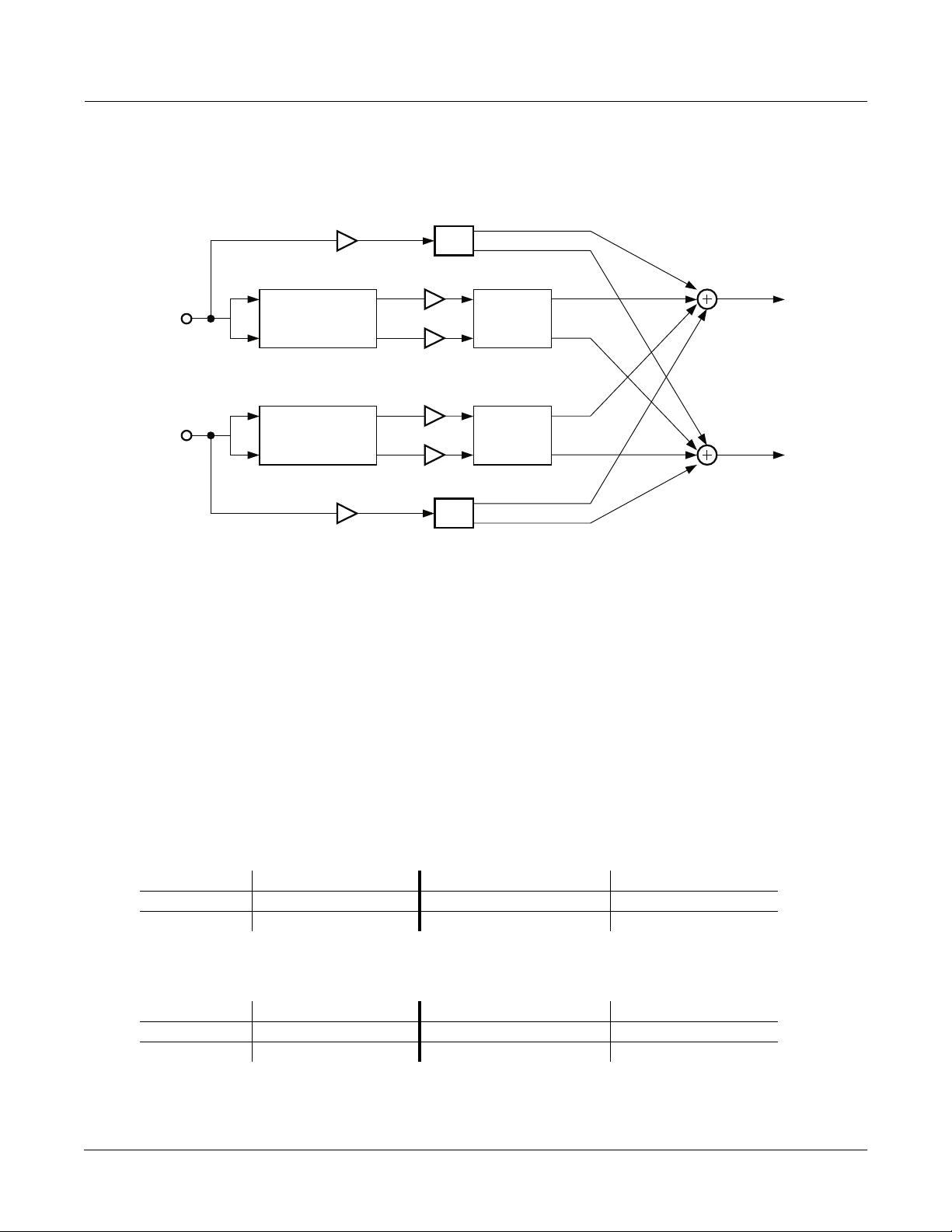
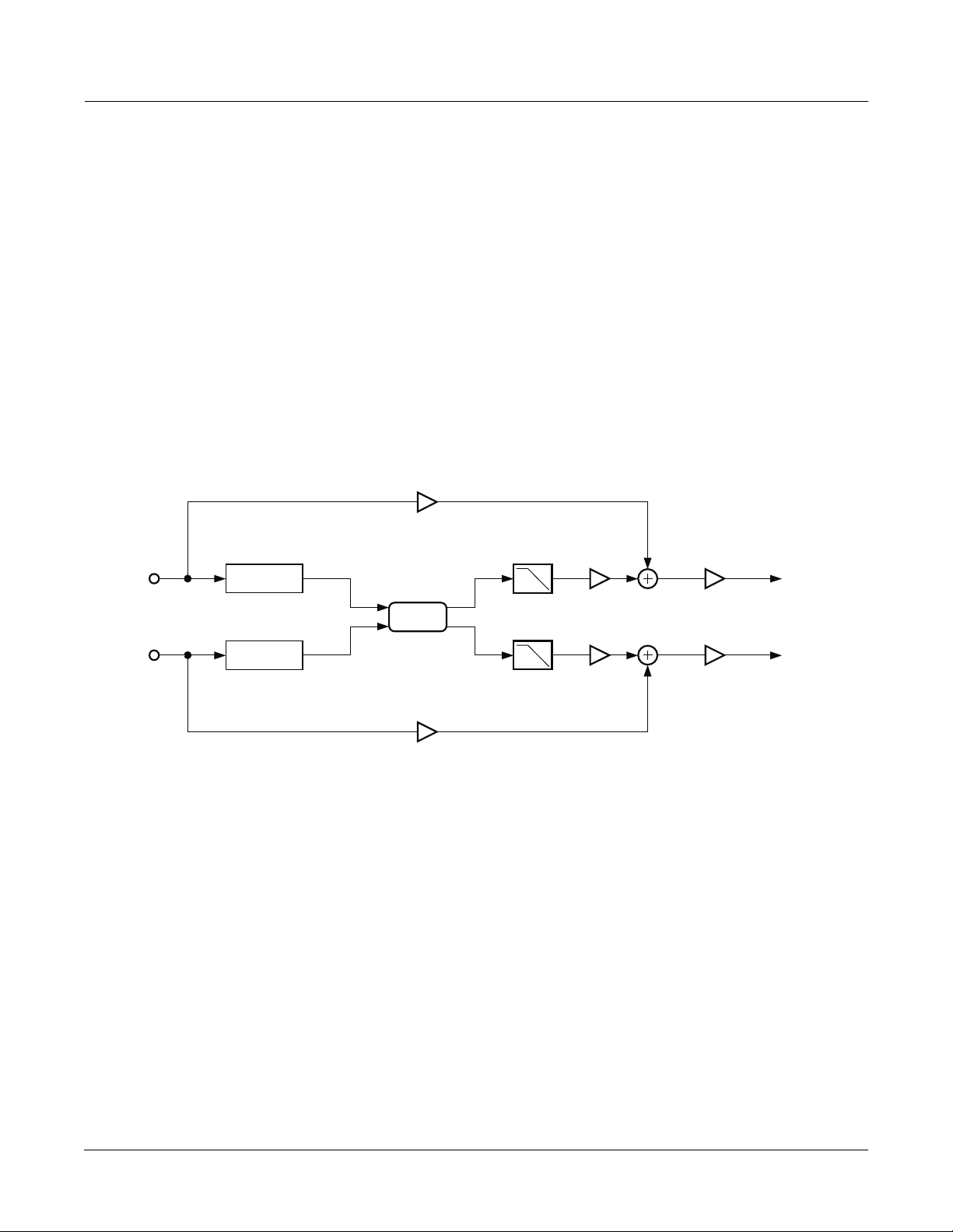
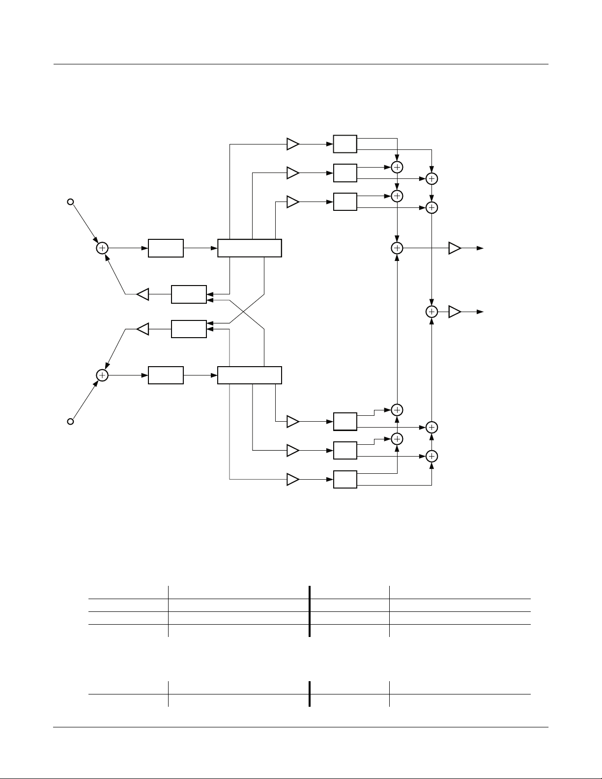
MiniVerb is a versatile stereo reverb is found in many combination algorithms, but is equally useful on its
own because of its small size. The main control for this effect is the Room Type parameter. Room Type
changes the structure of the algorithm to simulate many carefully crafted room types and sizes. Spaces
characterized as booths, small rooms, chambers, halls and large spaces can be selected.
Dry
L Input
R Input
Figure 10-1 Simplified Block Diagram of MiniVerb
Each Room Type incorporates different diffusion, room size and reverb density settings. The Room Types
were designed to sound best when Diff Scale, Size Scale and Density are set to the default values of 1.00x .
If you want a reverb to sound perfect immediately, set the Diff Scale, Size Scale and Density parameters to
1.00x , pick a Room Type and youÕll be on the way to a great sounding reverb. But if you want to
experiment with new reverb ßavors, changing the scaling parameters away from 1.00x can cause a subtle
(or drastic!) coloring of the carefully crafted Room Types.
Diffusion characterizes how the reverb spreads the early reßection out in time. At very low settings of Diff
Scale, the early reßections start to sound quite discrete, and at higher settings the early reßections are
L PreDelay
R PreDelay
Miniverb
Dry
Core
Wet Out Gain
L Output
R Output
10-8
Page 9
KDFX Algorithm Specifications
KDFX Reference
seamless. Density controls how tightly the early reßections are packed in time. Low Density settings have
the early reßections grouped close together, and higher values spread the reßections for a smoother reverb.
L Input
R Input
Dry
MiniVerb Balance
MiniVerb
Dry
Wet
Wet
Pan
Balance
Pan
L Output
R Output
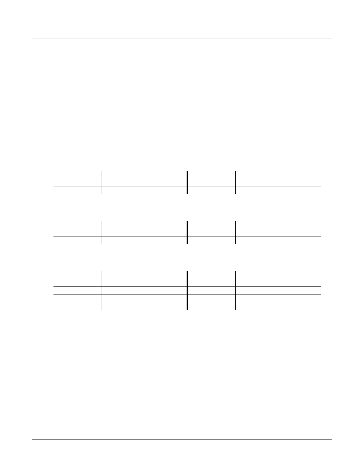
Figure 10-2 Simplified Block Diagram of Dual MiniVerb
Dual MiniVerb has a full MiniVerb, including Wet/Dry, Pre Delay and Out Gain controls, dedicated to
both the left and right channels. In Figure 10-2, the two blocks labeled MiniVerb contain a complete copy
of the contents of Figure 10-1. Dual MiniVerb gives you indepenent reverbs on both channels which has
obvious beneÞts for mono material. With stereo material, any panning or image placement can be
maintained, even in the reverb tails! This is pretty unusual behaviour for a reverb, since even real halls will
rapidly delocalize acoustic images in the reverberance. Since maintaining image placement in the
reverberation is so unusual, you will have to carefully consider whether it is appropriate for your
particular situation. To use Dual MiniVerb to maintain stereo signals in this manner, set the reverb
parameters for both channels to the same values. The Dry Pan and Wet Bal parameters should be fully left
-100% ) for the left MiniVerb and fully right ( 100% ) for the right MiniVerb.
(
MiniVerb Parameters
Page 1
Wet/Dry 0 to 100%wet Out Gain Off, -79.0 to 24.0 dB
Rvrb Time 0.5 to 30.0 s, Inf HF Damping 16 to 25088 Hz
L Pre Dly 0 to 620 ms R Pre Dly 0 to 620 ms
Page 2
Room Type Hall1 Diff Scale 0.00 to 2.00x
Size Scale 0.00 to 4.00x
Density 0.00 to 4.00x
10-9
Page 10
KDFX Reference
KDFX Algorithm Specifications
Dual MiniVerb Parameters
Page 1
L Wet/Dry 0 to 100%wet R Wet/Dry 0 to 100%wet
L Out Gain Off, -79.0 to 24.0 dB R Out Gain Off, -79.0 to 24.0 dB
L Wet Bal -100 to 100% R Wet Bal -100 to 100%
L Dry Pan -100 to 100% R Dry Pan -100 to 100%
Page 2
L RoomType Hall1
L RvrbTime 0.5 to 30.0 s, Inf
L Diff Scl 0.00 to 2.00x L Density 0.00 to 4.00x
L Size Scl 0.00 to 4.00x L HF Damp 16 to 25088 Hz
L PreDlyL 0 to 620 ms L PreDlyR 0 to 620 ms
Page 3
R RoomType Hall1
R RvrbTime 0.5 to 30.0 s, Inf
R Diff Scl 0.00 to 2.00x R Density 0.00 to 4.00x
R Size Scl 0.00 to 4.00x R HF Damp 16 to 25088 Hz
R PreDlyL 0 to 620 ms R PreDlyR 0 to 620 ms
Wet / Dry A simple mix of the reverb sound with the dry sound.
Out Gain
Rvrb Time
The overall gain or amplitude at the output of the effect.
The reverb time displayed is accurate for normal settings of the other parameters (HF
Damping = 25088kHz, and Diff Scale, Room Scale and Density = 1.00x). Changing Rvrb
Time to Inf creates an inÞnitely sustaining reverb.
HF Damping Reduces high frequency components of the reverb above the displayed cutoff frequency.
Removing higher reverb frequencies can often make rooms sound more natural.
L/R Pre Dly The delay between the start of a sound and the output of the Þrst reverb reßections from
that sound. Longer pre-delays can help make larger spaces sound more realistic. Longer
times can also help improve the clarity of a mix by separating the reverb signal from the
dry signal, so the dry signal is not obscured. Likewise, the wet signal will be more audible
if delayed, and thus you can get by with a dryer mix while maintaining the same
subjective wet/dry level.
Room Type Changes the conÞguration of the reverb algorithm to simulate a wide array of carefully
designed room types and sizes. This parameter effectively allows you to have several
different reverb algorithms only a parameter change away. Smaller Room Types will
sound best with shorter Rvrb Times, and vice versa. (Note that since this parameter
changes the structure of the reverb algorithm, you donÕt want to modulate it.)
10-10
Page 11

KDFX Reference
KDFX Algorithm Specifications
Diff Scale
Size Scale
Density
Wet Bal
A multiplier which affects the diffusion of the reverb. At 1.00x, the diffusion will be the
normal, carefully adjusted amount for the current Room Type. Altering this parameter
will change the diffusion from the preset amount.
A multiplier which changes the size of the current room. At 1.00x, the room will be the
normal, carefully tweaked size of the current Room Type. Altering this parameter will
change the size of the room, and thus will cause a subtle coloration of the reverb (since the
roomÕs dimensions are changing).
A multiplier which affects the density of the reverb. At 1.00x, the room density will be the
normal, carefully set amount for the current Room Type. Altering this parameter will
change the density of the reverb, which may color the room slightly.
In Dual MiniVerb, two mono signals (left and right) are fed into two separate stereo
reverbs. If you center the wet balance (0%), the left and right outputs of the reverb will be
sent to the Þnal output in equal amounts. This will add a sense of spaciousness
10-11
Page 12
KDFX Reference
KDFX Algorithm Specifications
3 Gated MiniVerb
A reverb and compressor in series.
PAUs: 2
This algorithm is a small reverb followed by a gate. The main control for the reverb is the Room Type
parameter. The main control for the reverb is the Room Type parameter. Room Type changes the structure
of the algorithm to simulate many carefully crafted room types and sizes. Spaces characterized as booths,
small rooms, chambers, halls and large spaces can be selected.
Each Room Type incorporates different diffusion, room size and reverb density settings. The Room Types
were designed to sound best when Diff Scale, Size Scale and Density are set to the default values of 1.00x.
If you want a reverb to sound perfect immediately, set the Diff Scale, Size Scale and Density parameters to
1.00x, pick a Room Type and youÕll be on the way to a great sounding reverb. But if you want experiment
with new reverb ßavors, changing the scaling parameters away from 1.00x can cause a subtle (or drastic!)
coloring of the carefully crafted Room Types.
Diffusion characterizes how the reverb spreads the early reßection out in time. At very low settings of Diff
Scale, the early reßections start to sound quite discrete, and at higher settings the early reßections are
seamless. Density controls how tightly the early reßections are packed in time. Low Density settings have
the early reßections grouped close together, and higher values spread the reßections for a smoother reverb.
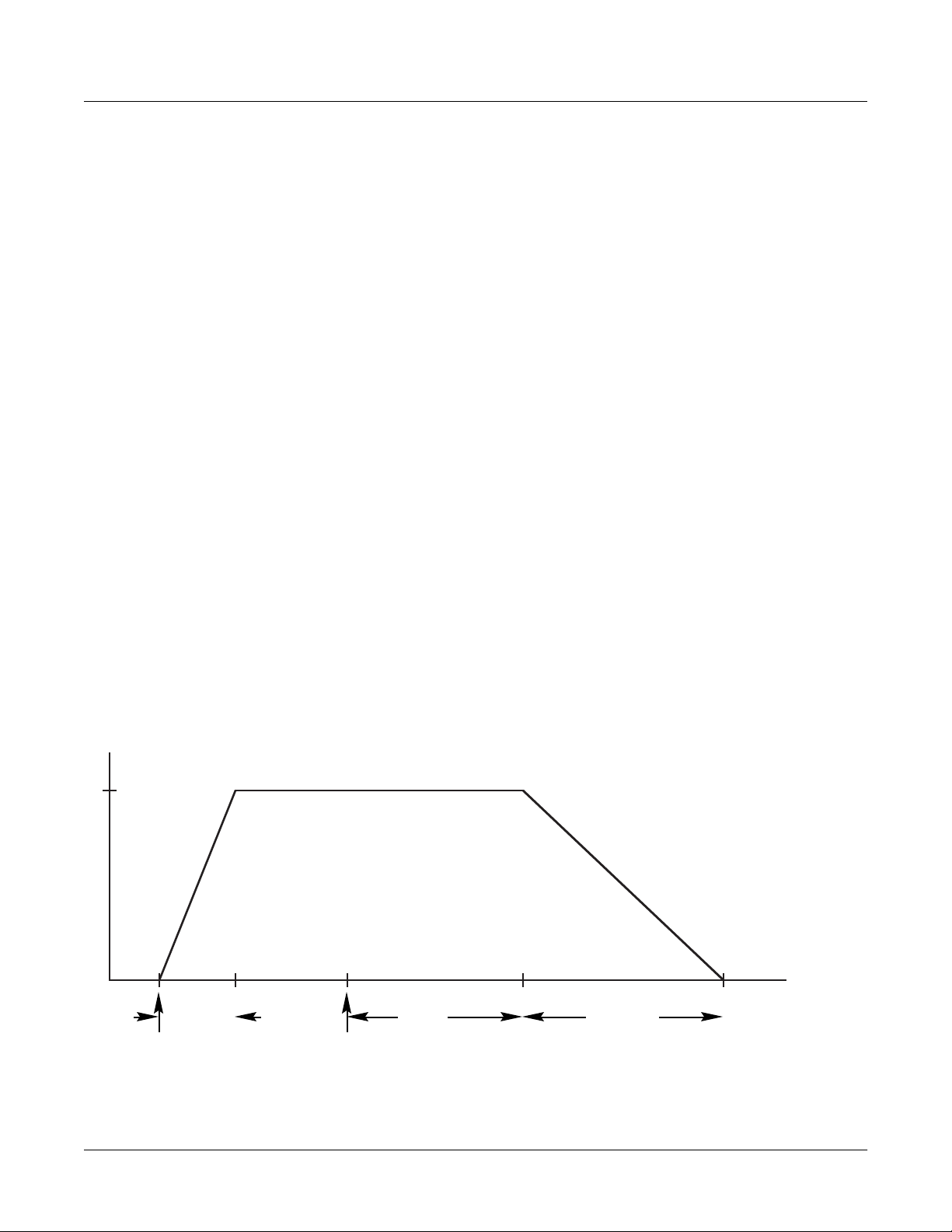
The gate turns the output of the reverb on and off based on the amplitude of the input signal.
A gate behaves like an on off switch for a signal. One or both input channels is used to control whether the
switch is on (gate is open) or off (gate is closed). The on/off control is called Òside chainÓ processing. You
select which of the two input channels or both is used for side chain processing. When you select both
channels, the sum of the left and right input amplitudes is used. The gate is opened when the side chain
amplitude rises above a level that you specify with the Threshold parameter.
The gate will stay open for as long as the side chain signal is above the threshold. When the signal drops
below the threshold, the gate will remain open for the time set with the Gate Time parameter. At the end of
the Gate Time, the gate closes. When the signal rises above threshold, it opens again. What is happening is
that the gate timer is being constantly retriggered while the signal is above threshold.
1
0
signal rises
above threshold
Figure 10-3 Gate Behavior
10-12
attack
time
signal falls
below threshold
gate
time
release
time
Page 13
KDFX Reference
KDFX Algorithm Specifications
If Gate Duck is turned on, then the behaviour of the gate is reversed. The gate is open while the side chain
signal is below threshold, and it closes when the signal rises above thresold.
If the gate opened and closed instantaneously, you would hear a large digital click, like a big knife switch
was being thrown. Obviously thatÕs not a good idea, so Gate Atk (attack) and Gate Rel (release) parameters
are use to set the times for the gate to open and close. More precisely, depending on whether Gate Duck is
off or on, Gate Atk sets how fast the gate opens or closes when the side chain signal rises above the
threshold. The Gate Rel sets how fast the gate closes or opens after the gate timer has elapsed.
The Signal Dly parameter delays the signal being gated, but does not delay the side chain signal. By
delaying the main signal relative to the side chain signal, you can open the gate just before the main signal
rises above threshold. ItÕs a little like being able to pick up the telephone before it rings!
Parameters
Page 1
Wet/Dry 0 to 100%wet Out Gain Off, -79.0 to 24.0 dB
Rvrb Time 0.5 to 30.0s, Inf HF Damping 16 to 25088 Hz
L Pre Dly 0 to 620ms R Pre Dly 0 to 620 ms
Page 2
Room Type Hall1 Diff Scale 0.00 to 2.00x
Size Scale 0.00 to 4.00x
Density 0.00 to 4.00x
Page 3
Gate Thres -79.0 to 0.0 dB Gate Time 0 to 3000 ms
Gate Duck In or Out Gate Atk 0.0 to 228.0 ms
Gate Rel 0 to 3000 ms
GateSigDly 0.0 to 25.0 ms
Reduction -dB 60 40 * 16 * 8 4 0
Wet/Dry A simple mix of the reverb sound with the dry sound. When set fully dry (0%), the gate is
still active.
Out Gain An overall level control of the effectÕs output (applied after the Wet/Dry mix).
Rvrb Time The reverb time displayed is accurate for normal settings of the other parameters (HF
Damping = 25088kHz, and Diff Scale, Room Scale and Density = 1.00x). Changing Rvrb
Time to Inf creates an inÞnitely sustaining reverb.
HF Damping Reduces high frequency components of the reverb above the displayed cutoff frequency.
Removing higher reverb frequencies can often make rooms sound more natural.
L/R Pre Dly The delay between the start of a sound and the output of the Þrst reverb reßections from
that sound. Longer pre-delays can help make larger spaces sound more realistic. Longer
times can also help improve the clarity of a mix by separating the reverb signal from the
dry signal, so the dry signal is not obscured. Likewise, the wet signal will be more audible
10-13
Page 14

KDFX Reference
KDFX Algorithm Specifications
if delayed, and thus you can get by with a dryer mix while maintaining the same
subjective wet/dry level.
Room Type The conÞguration of the reverb algorithm to simulate a wide array of carefully designed
room types and sizes. This parameter effectively allows you to have several different
reverb algorithms only a parameter change away. Smaller Room Types will sound best
with shorter Rvrb Times, and vice versa. (Note that since this parameter changes the
structure of the reverb algorithm, you may not modulate it.)
Diff Scale A multiplier which affects the diffusion of the reverb. At 1.00x, the diffusion will be the
normal, carefully adjusted amount for the current Room Type. Altering this parameter
will change the diffusion from the preset amount.
Size Scale A multiplier which changes the size of the current room. At 1.00x, the room will be the
normal, carefully tweaked size of the current Room Type. Altering this parameter will
change the size of the room, and thus will cause a subtle coloration of the reverb (since the
roomÕs dimensions are changing).
Density A multiplier which affects the density of the reverb. At 1.00x, the room density will be the
normal, carefully set amount for the current Room Type. Altering this parameter will
change the density of the reverb, which may color the room slightly.
Gate Thres The input signal level in dB required to open the gate (or close the gate if Gate Duck is on).
Gate Duck When set to ÒOffÓ, the gate opens when the signal rises above threshold and closes when
the gate time expires. When set to ÒOnÓ, the gate closes when the signal rises above
threshold and opens when the gate time expires.
Gate Time The time in seconds that the gate will stay fully on after the signal envelope rises above
threshold. The gate timer is started or restarted whenever the signal envelope rises above
threshold. If Retrigger is On, the gate timer is continually reset while the side chain signal
is above the threshold.
Gate Atk The attack time for the gate to ramp from closed to open (reverse if Gate Duck is on) after
the signal rises above threshold.
Gate Rel The release time for the gate to ramp from open to closed (reverse if Gate Duck is on) after
the gate timer has elapsed.
Signal Dly The delay in milliseconds (ms) of the reverb signal relative to the side chain signal. By
delaying the reverb signal, the gate can be opened before the reverb signal rises above the
gating threshold.
10-14
Page 15

KDFX Reference
KDFX Algorithm Specifications
Algorithms 4–11: Classic / TQ / Diffuse / Omni Reverbs
4 Classic Place
5 Classic V erb
6 TQ Place
7 TQ V erb
8 Diffuse Place
9 Diffuse V erb
10 OmniPlace
11 OmniV erb
Parameters
Absorption This controls the amount of reßective material that is in the space being
emulated, much like an acoustical absorption coefÞcient. The lower the setting,
the longer it will take for the sound to die away. A setting of 0% will cause an
inÞnite decay time.
Rvrb Time Adjusts the basic decay time of the late portion of the reverb.
LateRvbTim Adjusts the basic decay time of the late portion of the reverb after diffusion.
HF Damping This controls the amount of high frequency energy that is absorbed as the
reverb decays. The values set the cutoff frequency of the 1 pole (6dB/oct) lopass
Þlter within the reverb feedback loop.
L Pre Dly, R Pre Dly These control the amount that each channel of the reverb is delayed relative to
the dry signal. Setting different lengths for both channels can de-correlate the
center portion of the reverb image and make it seem wider. This only affects the
late reverb in algorithms that have early reßections.
Lopass Controls the cutoff frequency of a 1 pole (6dB/oct) lopass Þlter at the output of
the reverb. This only affects the late reverb in algorithms that have early
reßections.
EarRef Lvl Adjusts the mix level of the early reßection portion of algorithms offering early
reßections.
Late Lvl Adjusts the mix level of the late reverb portion of algorithms offering early
reßections.
Room Type This parameter selects the basic type of reverb being emulated, and should be
your starting point when creating your own reverb presets. Due to the inherent
complexity of reverb algorithms and the sheer number of variables responsible
for their character, the Room Type parameter provides condensed preset
collections of these variables. Each Room Type preset has been painstakingly
selected by Kurzweil engineers to provide the best sounding collection of
mutually complementary variables modelling an assortment of reverb families.
When a room type is selected, an entire incorporated set of delay lengths and
diffusion settings are established within the algorithm. By using the Size Scale,
DiffAmtScl, DiffLenScl, and Inj Spread parameters, you may scale individual
elements away from their preset value. When set to 1.00x, each of these
10-15
Page 16

KDFX Reference
KDFX Algorithm Specifications
Size Scale This parameter scales the inherent size of the reverb chosen by Room Type. For
InÞnDecay Found in ÒVerbÓ algorithms. When turned ÒOnÓ, the reverb tail will decay
LF Split Used in conjunction with LF Time. This controls the upper frequency limit of
LF Time Used in conjunction with LF Split. This modiÞes the decay time of the energy
elements are accurately representing their preset values determined by the
current Room Type.
Room Types with similar names in different reverb algorithms do not sound the
same. For example, Hall1 in Diffuse Verb does not sound the same as Hall1 in
TQ Verb.
a true representation of the selected Room Type size, set this to 1.00x. Scaling
the size below this will create smaller spaces, while larger scale factors will
create large spaces. See Room Type for more detailed information.
indeÞnitely. When turned ÒOffÓ, the decay time is determined by the ÒRvrb
TimeÓ or ÒLateRvbTimÓ parameters.
the low frequency decay time multiplier. Energy below this frequency will
decay faster or slower depending on the LF Time parameter.
below the LF Split frequency. A setting of 1.00x will make low frequency energy
decay at the rate determined by the decay time. Higher values will cause low
frequency energy to decay slower, and lower values will cause it to decay more
quickly.
TrebShlf F Adjusts the frequency of a high shelving Þlter at the output of the late reverb.
TrebShlf G Adjusts the gain of a high shelving Þlter at the output of the late reverb.
BassShlf F Adjusts the frequency of a low shelving Þlter at the output of the late reverb.
BassShlf G Adjusts the gain of a low shelving Þlter at the output of the late reverb.
DiffAmtScl Adjusts the amount of diffusion at the onset of the reverb. For a true
representation of the selected Room Type diffusion amount, set this to 1.00x.
DiffLenScl Adjusts the length of the diffusion at the onset of the reverb. For a true
representation of the selected Room Type diffusion length, set this to 1.00x.
DiffExtent Adjust the onset diffusion duration. Higher values create longer diffuse bursts
at the onset of the reverb.
Diff Cross Adjusts the onset diffusion cross-coupling character. Although subtle, this
parameter bleeds left and right channels into each other during onset diffusion,
and also in the body of the reverb. 0% setting will disable this. Increasing this
value in either the positive or negative direction will increase its affect.
Expanse Amount of late reverb energy biased toward the edges of the stereo image. A
setting of 0% will bias energy towards the center. Moving away from 0% will
bias energy towards the sides. Positive and negative values will have a different
character.
LFO Rate Adjusts the rate at which certain reverb delay lines move. See LFO Depth for
more information.
10-16
LFO Depth Adjusts the detuning depth in cents caused by a moving reverb delay line.
Moving delay lines can imitate voluminous ßowing air currents and reduce
unwanted artifacts like ringing and ßutter when used properly. Depth settings
under 1.5ct with LFO Rate settings under 1.00Hz are recommended for
Page 17

KDFX Reference
KDFX Algorithm Specifications
modeling real spaces. High depth settings can create chorusing qualities, which
wonÕt be unsuitable for real acoustic spaces, but can nonetheless create
interesting effects. Instruments that have little if no inherent pitch ßuctuation
(like piano) are much more sensitive to this LFO than instruments that normally
have a lot of vibrato (like voice) or non-pitched instruments (like snare drum).
Inj Build Used in conjunction with Inj Spread, this adjusts the envelope of the onset of the
reverb. SpeciÞcally, it tapers the amplitudes of a series of delayed signals
injected into the body of the reverb. Values above 0% will produce a faster
build, while values below 0% will cause the build to be more gradual.
Inj Spread Used in conjunction with Inj Build, this scales the length of the series of delays
injected into the body of the reverb. For a true representation of the selected
Room Type injector spread, set this to 1.00x.
Inj LP This adjusts the cutoff frequency of a 1 pole (6dB/oct) lopass Þlter applied to
the signal being injected into the body of the reverb.
Inj Skew Adjusts the amount of delay applied to either the left or right channel of the
reverb injector. Positive values delay the right channel while negative values
delay the left channel.
E DiffAmt Adjusts the amount of diffusion applied to the early reßection network.
E DfLenScl Adjusts the length of diffusion applied to the early reßection network. This is
inßuenced by E PreDlyL and E PreDlyR.
E Dly Scl Scales the delay lengths inherent in the early reßection network.
E Build Adjusts the envelope of the onset of the early reßections. Values above 0% will
create a faster attack while values below 0% will create a slower attack.
E Fdbk Amt Adjusts the amount of the output of an early reßection portion that is fed back
into the input of the opposite channel in front of the early pre-delays. Overall, it
lengthens the decay rate of the early reßection network. Negative values
polarity invert the feedback signal.
E HF Damp This adjusts the cutoff frequency of a 1 pole (6dB/oct) lopass Þlter applied to
the early reßection feedback signal.
E PreDlyL, E PreDlyR Adjusts how much the early reßections are delayed relative to the dry signal.
These are independent of the late reverb predelay times, but will inßuence E
Dly Scl.
E Dly L, E Dly R Adjusts the left and right early reßection delays fed to the same output
channels.
E Dly LX, E Dly RX Adjusts the left and right early reßection delays fed to the opposite output
channels.
E DifDlyL, E DifDlyR Adjusts the diffusion delays of the diffusers on delay taps fed to the same
output channels.
E DifDlyLX, E DifDlyRX Adjusts the diffusion delays of the diffusers on delay taps fed to the opposite
output channels.
E X Blend Adjusts the balance between early reßection delay tap signals with diffusers fed
to their same output channel, and those fed to opposite channels. 0% will only
allow delay taps being fed to opposite output channels to be heard, while 100%
allows only delay taps going to the same channels to be heard.
10-17
Page 18
KDFX Reference
KDFX Algorithm Specifications
12 Panaural Room
Room reverberation algorithm
PAUs: 3
The Panaural Room reverberation is implemented using a special network arrangement of many delay
lines that guarantees colorless sound. The reverberator is inherently stereo with each input injected into
the "room" at multiple locations. The signals entering the reverberator Þrst pass through a shelving bass
equalizer with a range of +/-15dB. To shorten the decay time of high frequencies relative to mid
frequencies, low pass Þlters controlled by HF Damping are distributed throughout the network. Room
Size scales all the delay times of the network (but not the Pre Dly or Build Time), to change the simulated
room dimension over a range of 1 to 16m. Decay Time varies the feedback gains to achieve decay times
from 0.5 to 100 seconds. The Room Size and Decay Time controls are interlocked so that a chosen Decay
Time will be maintained while Room Size is varied. A two input stereo mixer, controlled by Wet/Dry and
Out Gain, feeds the output.
Dry
L Input
R Input
PreDelay
PreDelay
Dry
Reverb
Wet
Out Gain
Figure 10-4 Simplified block diagram of Panaural Room.
The duration and spacing of the early reßections are inßuenced by Room Size and Build Time, while the
number and relative loudness of the individual reßections are inßuenced by Build Env. When Build Env is
near 0 or 100%, fewer reßections are created. The maximum number of important early reßections, 13, is
achieved at a setting of 50%.
To get control over the growth of reverberation, the left and right inputs each are passed through an
"injector" that can extend the source before it drives the reverberator. Only when Build Env is set to 0% is
the reverberator driven in pure stereo by the pure dry signal. For settings of Build Env greater than 0%, the
reverberator is fed multiple times. Build Env controls the injector so that the reverberation begins abruptly
(0%), builds immediately to a sustained level (50%), or builds gradually to a maximum (100%). Build Time
varies the injection length over a range of 0 to 500ms. At a Build Time of 0ms, there is no extension of the
build time. In this case, the Build Env control adjusts the density of the reverberation, with maximum
density at a setting of 50%. In addition to the two build controls, there is an overall Pre Dly control that can
delay the entire reverberation process by up to 500ms.
L Output
R Output
10-18
Page 19
KDFX Reference
KDFX Algorithm Specifications
Parameters
Page 1
Wet/Dry 0 to 100%wet Out Gain Off, -79.0 to 24.0
Room Size 1.0 to 16.0 m
Pre Dly 0 to 500 ms Decay Time 0.5 to 100.0 s
HF Damping 16 to 25088 Hz
Page 2
Bass Gain -15 to 15 dB Build Time 0 to 500 ms
Build Env 0 to 100%
Wet/Dry The amount of the stereo reverberator (wet) signal relative to the original input (dry)
signal to be output. The dry signal is not affected by the Bass Gain control. The wet signal
is affected by the Bass Gain control and by all the other reverberator controls. The balance
between wet and dry signals is an extremely important factor in achieving a good mix.
Emphasizing the wet signal gives the effect of more reverberation and of greater distance
from the source.
Out Gain The overall output level for the reverberation effect, and controls the level for both the wet
and dry signal paths.
Decay Time The reverberation decay time (mid-band "RT60"), the time required before the
reverberation has died away to 60dB below its "running" level. Adjust decay time
according to the tempo and articulation of the music and to taste.
HF Damping Adjusts low pass Þlters in the reverberator so that high frequencies die away more quickly
than mid and low frequencies. This shapes the reverberation for a more natural, more
acoustically accurate sound.
Bass Gain Shapes the overall reverberation signal's bass content, but does not modify the decay time.
Reduce the bass for a less muddy sound, raise it slightly for a more natural acoustic effect.
Room Size Choosing an appropriate room size is very important in getting a good reverberation
effect. For impulsive sources, such as percussion instruments or plucked strings, increase
the size setting until discrete early reßections become audible, and then back it off slightly.
For slower, softer music, use the largest size possible. At lower settings, Room Size leads
to coloration, especially if the Decay Time is set too high.
Pre Dly Introducing predelay creates a gap of silence between that allows the dry signal to stand
out with greater clarity and intelligibility against the reverberant background. This is
especially helpful with vocal or classical music.
Build Time Similar to predelay, but more complex, larger values of Build Time slow down the
building up of reverberation and can extend the build up process. Experiment with Build
Time and Build Env and use them to optimize the early details of reverberation. A Build
Time of 0ms and a Build Env of 50% is a good default setting that yields a fast arriving,
maximally dense reverberation.
Build Env When Build Time has been set to greater than about 80ms, Build Env begins to have an
audible inßuence on the early unfolding of the reverberation process. For lower density
reverberation that starts cleanly and impulsively, use a setting of 0%. For the highest
density reverberation, and for extension of the build up period, use a setting of 50%. For
10-19
Page 20

KDFX Reference
KDFX Algorithm Specifications
an almost reverse reverberation, set Build Env to 100%. You can think of Build Env as
setting the position of a see-saw. The left end of the see-saw represents the driving of the
reverberation at the earliest time, the pivot point as driving the reverberation at mid-point
in the time sequence, and the right end as the last signal to drive the reverberator. At
settings near 0%, the see-saw is tilted down on the right: the reverberation starts abruptly
and the drive drops with time. Near 50%, the see-saw is level and the reverberation is
repetitively fed during the entire build time. At settings near 100%, the see-saw is tilted
down on the left, so that the reverberation is hit softly at Þrst, and then at increasing level
until the end of the build time.
10-20
Page 21
KDFX Reference
KDFX Algorithm Specifications
13 Stereo Hall
A stereo hall reverberation algorithm.
PAUs: 3
The Stereo Hall reverberation is implemented using a special arrangement of all pass networks and delay
lines which reduces coloration and increases density. The reverberator is inherently stereo with each input
injected into the "room" at multiple locations. To shorten the decay time of low and high frequencies
relative to mid frequencies, bass equalizers and low pass Þlters, controlled by Bass Gain and by HF
Damping, are placed within the network. Room Size scales all the delay times of the network (but not the
Pre Dly or Build Time), to change the simulated room dimension over a range of 10 to 75m. Decay Time
varies the feedback gains to achieve decay times from 0.5 to 100 seconds. The Room Size and Decay Time
controls are interlocked so that a chosen Decay Time will be maintained while Room Size is varied. At
smaller sizes, the reverb becomes quite colored and is useful only for special effects. A two input stereo
mixer, controlled by Wet/Dry and Out Gain, feeds the output. The Lowpass control acts only on the wet
signal and can be used to smooth out the reverb high end without modifying the reverb decay time at high
frequencies.
Dry
L Input
R Input
PreDelay
PreDelay
Reverb
Dry
Wet
Out Gain
L Output
R Output
Figure 10-5 Simplified block diagram of Stereo Hall.
Within the reverberator, certain delays can be put into a time varying motion to break up patterns and to
increase density in the reverb tail. Using the LFO Rate and Depth controls carefully with longer decay
times can be beneÞcial. But beware of the pitch shifting artifacts which can accompany randomization
when it is used in greater amounts. Also within the reverberator, the Diffusion control can reduce the
diffusion provided by some all pass networks. While the reverb will eventually reach full diffusion
regardless of the Diffusion setting, the early reverb diffusion can be reduced, which sometimes is useful to
help keep the dry signal "in the clear".
The reverberator structure is stereo and requires that the dry source be applied to both left and right
inputs. If the source is mono, it should still be applied (pan centered) to both left and right inputs. Failure
to drive both inputs will result in offset initial reverb images and later ping-ponging of the reverberation.
Driving only one input will also increase the time required to build up reverb density.
To gain control over the growth of reverberation, the left and right inputs each are passed through an
"injector" that can extend the source before it drives the reverberator. Only when Build Env is set to 0% is
the reverberator driven in pure stereo by the pure dry signal. For settings of Build Env greater than 0%, the
reverberator is fed multiple times. Build Env controls the injector so that the reverberation begins abruptly
(0%), builds immediately to a sustained level (50%), or builds gradually to a maximum (100%). Build Time
10-21
Page 22
KDFX Reference
KDFX Algorithm Specifications
varies the injection length over a range of 0 to 500ms. At a Build Time of 0ms, there is no extension of the
build time. In this case, the Build Env control adjusts the density of the reverberation, with maximum
density at a setting of 50%. In addition to the two build controls, there is an overall Pre Dly control that can
delay the entire reverberation process by up to 500ms.
Parameters
Page 1
Wet/Dry 0 to 100%wet Out Gain Off, -79.0 to 24.0 dB
Room Size 2.0 to 15.0 m Diffusion 0 to 100%
Pre Dly 0 to 500 ms Decay Time 0.5 to 100.0 ms
HF Damping 16 to 25088 Hz
Page 2
Bass Gain -15 to 0 dB Build Time 0 to 500 ms
Lowpass 16 to 25088 Hz Build Env 0 to 100%
LFO Rate 0.00 to 5.10 Hz
LFO Depth 0.00 to 10.20 ct
Wet/Dry The amount of the stereo reverberator (wet) signal relative to the original input
(dry) signal to be output. The dry signal is not affected by the HF Roll control.
The wet signal is affected by the HF Roll control and by all the other
reverberator controls. The balance between wet and dry signals is an extremely
important factor in achieving a good mix. Emphasizing the wet signal gives the
effect of more reverberation and of greater distance from the source.
Out Gain The overall output level for the reverberation effect, and controls the level for
both the wet and dry signal paths.
Decay Time The reverberation decay time (mid-band "RT60"), the time required before the
reverberation has died away to 60dB below its "running" level. Adjust decay
time according to the tempo and articulation of the music and to taste.
HF Damping Adjusts low pass Þlters in the reverberator so that high frequencies die away
more quickly than mid and low frequencies. This shapes the reverberation for a
more natural, more acoustically accurate sound.
Bass Gain Adjusts bass equalizers in the reverberator so that low frequencies die away
more quickly than mid and high frequencies. This can be used to make the
reverberation less muddy.
Lowpass Used to shape the overall reverberation signal's treble content, but does not
modify the decay time. Reduce the treble for a softer, more acoustic sound.
Room Size Choosing an appropriate room size is very important in getting a good
reverberation effect. For impulsive sources, such as percussion instruments or
plucked strings, increase the size setting until discrete early reßections become
audible, and then back it off slightly. For slower, softer music, use the largest
size possible. At lower settings, RoomSize leads to coloration, especially if the
DecayTime is set too high.
10-22
Page 23

KDFX Reference
KDFX Algorithm Specifications
Pre Dly Introducing predelay creates a gap of silence between that allows the dry signal
to stand out with greater clarity and intelligibility against the reverberant
background. This is especially helpful with vocal or classical music.
Build Time Similar to predelay, but more complex, larger values of BuildTime slow down
the building up of reverberation and can extend the build up process.
Experiment with BuildTime and BuildEnv and use them to optimize the early
details of reverberation. A BuildTime of 0ms and a BuildEnv of 0% is a good
default setting that yields fast arriving, natural reverberation.
Build Env When BuildTime has been set to greater than about 80ms, BuildEnv begins to
have an audible inßuence on the early unfolding of the reverberation process.
For lower density reverberation that starts cleanly and impulsively, use a
setting of 0%. For the highest density reverberation, and for extension of the
build up period, use a setting of 50%. For an almost reverse reverberation, set
BuildEnv to 100%. You can think of BuildEnv as setting the position of a seesaw. The left end of the see-saw represents the driving of the reverberation at
the earliest time, the pivot point as driving the reverberation at mid-point in the
time sequence, and the right end as the last signal to drive the reverberator. At
settings near 0%, the see-saw is tilted down on the right: the reverberation starts
abruptly and the drive drops with time. Near 50%, the see-saw is level and the
reverberation is repetitively fed during the entire build time. At settings near
100%, the see-saw is tilted down on the left, so that the reverberation is hit softly
at Þrst, and then at increasing level until the end of the build time.
LFO Rate and Depth Within the reverberator, the certain delay values can be put into a time varying
motion to break up patterns and to increase density in the reverb tail. Using the
LFO Rate and Depth controls carefully with longer decay times can be
beneÞcial. But beware of the pitch shifting artifacts which can accompany
randomization when it is used in greater amounts.
Diffusion Within the reverberator, the Diffusion control can reduce the diffusion provided
some of the all pass networks. While the reverb will eventually reach full
diffusion regardless of the Diffusion setting, the early reverb diffusion can be
reduced, which sometimes is useful to help keep the dry signal "in the clear."
10-23
Page 24

KDFX Reference
KDFX Algorithm Specifications
14 Grand Plate
A plate reverberation algorithm.
PAUs: 3
This algorithm emulates an EMT 140 steel plate reverberator. Plate reverberators were manufactured
during the 1950's, 1960's, 1970's, and perhaps into the 1980's. By the end of the 1980's, they had been
supplanted in the marketplace by digital reverbertors, which Þrst appeared in 1976. While a handful of
companies made plate reverberators, EMT (Germany) was the best known and most popular.
A plate reverberator is generally quite heavy and large, perhaps 4 feet high by 7 feet long and a foot thick.
They were only slightly adjustable, with controls for high frequency damping and decay time. Some were
stereo in, stereo out, others mono in, mono out.
A plate reverb begins with a sheet of plate steel suspended by its edges, leaving the plate free to vibrate. At
one (or two) points on the plate, an electromagnetic driver (sort of a small loudspeaker without a cone) is
arranged to couple the dry signal into the plate, sending out sound vibrations into the plate in all
directions. At one or two other locations, a pickup is placed, sort of like a dynamic microphone whose
diaphragm is the plate itself, to pick up the reverberation.
Since the sound waves travel very rapidly in steel (faster than they do in air), and since the dimensions of
the plate are not large, the sound quickly reaches the plate edges and reßects from them. This results in a
very rapid build up of the reverberation, essentially free of early reßections and with no distinguishable
gap before the onset of reverb.
Plates offered a wonderful sound of their own, easily distinguished from other reverberators in the predigital reverb era, such as springs or actual "echo" chambers. Plates were bright and diffused (built up
echo density) rapidly. Curiously, when we listen to a vintage plate today, we Þnd that the much vaunted
brightness is nothing like what we can accomplish digitally; we actually have to deliberately reduce the
brightness of a plate emulation to match the sound of a real plate. Similarly, we Þnd that we must throttle
back on the low frequency content as well.
The algorithm developed for Grand Plate was carefully crafted for rapid diffusion, low coloration,
freedom from discrete early reßections, and "brightness." We also added some controls that were never
present in real plates: size, pre delay of up to 500ms, LF damping, low pass roll off, and bass roll off.
Furthermore, we allow a wider range of decay time adjustment than a conventional plate. Once the
algorithm was complete, we tuned it by presenting the original EMT reverb on one channel and the Grand
Plate emulation on the other. A lengthy and careful tuning of Grand Plate (tuning at the micro detail level
of each delay and gain in the algorithm) was carried out until the stereo spread of this reverb was matched
in all the time periods--early, middle, and late.
The heart of this reverb is the plate simulation network, with its two inputs and two outputs. It is a full
stereo reverberation network, which means that the left and right inputs get slightly different treatment in
the reverberator. This yields a richer, more natural stereo image from stereo sources. If you have a mono
source, assign it to both inputs for best results.
The incoming left source is passed through predelay, low pass (Lowpass), and bass shelf (Bass Gain)
blocks. The right source is treated similarly.
There are low pass Þlters (HF Damping) and high pass Þlters (LF Damping) embedded in the plate
simulation network to modify the decay times. The reverb network also accomodates the Room Size and
Decay Time controls.
10-24
An output mixer assembles dry and wet signals.
Page 25
KDFX Reference
KDFX Algorithm Specifications
Parameters
Page 1
Wet/Dry 0 to 100%wet Out Gain Off, -79.0 to 24.0 dB
Room Size 1.00 to 4.00 m
Pre Dly 0 to 500 ms Decay Time 0.2 to 5.0 s
HF Damping 16 to 25088 Hz LF Damping 1 to 294 Hz
Page 2
Lowpass 16 to 25088 Hz Bass Gain -15 to 0 dB
Wet/Dry The amount of the stereo reverberator (wet) signal relative to the original input (dry)
signal sent to the output. The dry signal is not affected by the Lowpass or Bass Gain
controls. The wet signal is affected by the Lowpass and Bass Gain controls and by all the
other reverberator controls. The balance between wet and dry signals is an extremely
important factor in achieving a good mix. Emphasizing the wet signal gives the effect of
more reverberation and of greater distance from the source.
Out Gain The overall output level for the reverberation effect and controls the level for both the wet
and dry signal paths.
Room Size Choosing an appropriate room size is very important in getting a good reverberation
effect. For impulsive sources, such as percussion instruments or plucked strings, increase
the size setting until discrete reßections become audible, and then back it off slightly. For
slower, softer music, use the largest size possible. At lower settings, Room Size leads to
coloration, especially if the Decay Time is set too high. To emulate a plate reverb, this
control is typically set to 1.9m.
Pre Dly Introducing predelay creates a gap of silence between the dry sound and the
reverberation, allowing the dry signal to stand out with greater clarity and intelligibility
against the reverberant background. Especially helpful with vocals or classical music.
Decay Time The reverberation decay time (mid-band "RT60"), the time required before the
reverberation has died away to 60dB below its "running" level. Adjust decay time
according to the tempo and articulation of the music. To emulate a plate reverb, this
control is typically set in the range of 1 to 5 seconds.
HF Damping Adjusts low pass Þlters in the reverberator so that high frequencies die away more quickly
than mid and low frequencies. This shapes the reverberation for a more natural, more
acoustically accurate sound. To emulate a plate reverb, a typical value is 5920Hz.
LF Damping Adjusts high pass Þlters in the reverberator so that low frequencies die away more quickly
than mid and high frequencies. This shapes the reverberation for a more natural, more
acoustically accurate sound. To emulate a plate reverb, this control is typically set to 52
Hz.
Lowpass Shapes the overall reverberation signal's treble content, but does not modify the decay
time. Reduce the treble for a duller, more natural acoustic effect. To emulate a plate reverb,
this control is typically set to 3951Hz.
Bass Gain Shapes the overall reverberation signal's bass content, but does not modify the decay time.
Reduce the bass for a less muddy sound. To emulate a plate reverb, this control is typically
set to -12dB.
10-25
Page 26
KDFX Reference
KDFX Algorithm Specifications
15 Finite V erb
Reverse reverberation algorithm.
PAUs: 3
The left and right sources are summed before being fed into a tapped delay line which directly simulates
the impulse response of a reverberator. The taps are placed in sequence from zero delay to a maximum
delay value, at quasi-regular spacings. By varying the coefÞcients with which these taps are summed, one
can create the effect of a normal rapidly building/slowly decaying reverb or a reverse reverb which builds
slowly then stops abruptly.
A special tap is picked off the tapped delay line and its length is controlled by Dly Length. It can be
summed into the output wet mix (Dly Lvl) to serve as the simulated dry source that occurs after the
reverse reverb sequence has built up and ended. It can also be fed back for special effects. Fdbk Lvl and HF
Damping tailor the gain and spectrum of the feedback signal. Despite the complex reverb-like sound of the
tapped delay line, the Feedback tap is a pure delay. Feeding it back is like reapplying the source, as in a
simple tape echo.
Dly Length and Rvb Length range from 300 to 3000 milliseconds. With the R1 Rvb Env variants, Rvb
Length corresponds to a decay time (RT60).
To make things a little more interesting, the tapped delay line mixer is actually broken into three mixers,
an early, middle, and late mixer. Each mixes its share of taps and then applies the submix to a low pass
Þlter (cut only) and a simple bass control (boost and cut). Finally, the three equalized sub mixes are mixed
into one signal. The Bass and Damp controls allow special effects such as a reverb that begins dull and
increases in two steps to a brighter sound.
The Rvb Env control selects 27 cases of envelope gains for the taps. Nine cases emulate a normal forward
evolving reverb, but with some special twists. Cases FWD R1xx have a single reverb peak, with a fast
attack and slower decay. The sub cases FWD R1Sx vary the sharpness of the envelope, from dullest (S1) to
sharpest (S3). The sub cases FWD R2xx have two peaks; that is, the reverb builds, decays, builds again, and
decays again. The sub cases FWD R3xx have three peaks.
The sub cases SYM have a symmetrical build and decay time. The cases R1 build to a single peak, while R2
and R3 have two and three peaks, respectively.
The sub cases REV simulate a reverse reverb effect. REV R1xx imitates a backward running reverb, with a
long rising "tail" ending abruptly (followed, optionally, by the "dry" source mixed by Dly Lvl). Once again,
the number of peaks and the sharpness are variable.
The usual Wet/Dry and Output Gain controls are provided.
Parameters
Page 1
Wet/Dry 0 to 100%wet Out Gain Off, -79.0 to 24.0 dB
Fdbk Lvl 0 to 100%
HF Damping 16 to 25088 Hz
Page 2
10-26
Dly Lvl 0 to 100% Rvb Env REV R1S1
Dly Length 300 to 3000 ms Rvb Length 300 to 3000 ms
Page 27
KDFX Reference
KDFX Algorithm Specifications
Page 3
Early Bass -15 to 15 dB Early Damp 16 to 25088 Hz
Mid Bass -15 to 15 dB Mid Damp 16 to 25088 Hz
Late Bass -15 to 15 dB Late Damp 16 to 25088 Hz
Wet/Dry Wet/Dry sets the relative amount of wet signal and dry signal. The wet signal
consistts of the reverb itself (stereo) and the delayed mono signal arriving after
the reverb has ended (simulating the dry source in the reverse reverb sequence).
The amount of the delayed signal mixed to the Wet signal is separately
adjustable with the Dly Lvl control. The Dry signal is the stereo input signal.
Out Gain This controls the level of the output mix, wet and dry, sent back into the K2600.
Fdbk Lvl This controls the feedback gain of the separate, (mono) delay tap. A high value
contributes a long repeating echo character to the reverb sound.
HF Damping HF Damping adjusts a low pass Þlter in the late delay tap feedback path so that
high frequencies die away more quickly than mid and low frequencies.
Dly Lvl This adjusts the level of the separate, (mono) delay tap used to simulate the dry
source of a reverse reverb effect. This same tap is used for feedback.
Dly Length Sets the length (in milliseconds), of the separate, (mono) delay tap used to
simulate the dry source of a reverse reverb effect. This same tap is used for
feedback.
Rvb Env The Rvb Env control selects 27 cases of envelope gains for the taps. Nine cases
emulate a normal forward evolving reverb, another nine emulate a reverb
building symmetrically to a peak at the mid point, while the last nine cases
emulate a reverse building reverb. For each major shape, there are three
variants of one, two, and three repetitions and three variants of envelope
sharpness.
Rvb Length Sets the length (in milliseconds), from start to Þnish, of the reverberation
process. This parameter is essentially the decay time or RT60 for the Rvb Env
cases ..R1.. where there is only one repetition.
Bass Early, Mid, and Late. These bass controls shape the frequency response (boost
or cut) of the three periods of the Þnite reverb sequence. Use them to tailor the
way the reverb bass content changes with time.
Damp Early, Mid, and Late. These treble controls shape the frequency response (cut
only) of the three periods of the Þnite reverb sequence. Use them to tailor the
way the reverb treble content changes with time.
10-27
Page 28

KDFX Reference
KDFX Algorithm Specifications
130 Complex Echo
Multitap delay line effect consisting of 6 independent output taps and 4 independent feedback taps
PAUs: 1
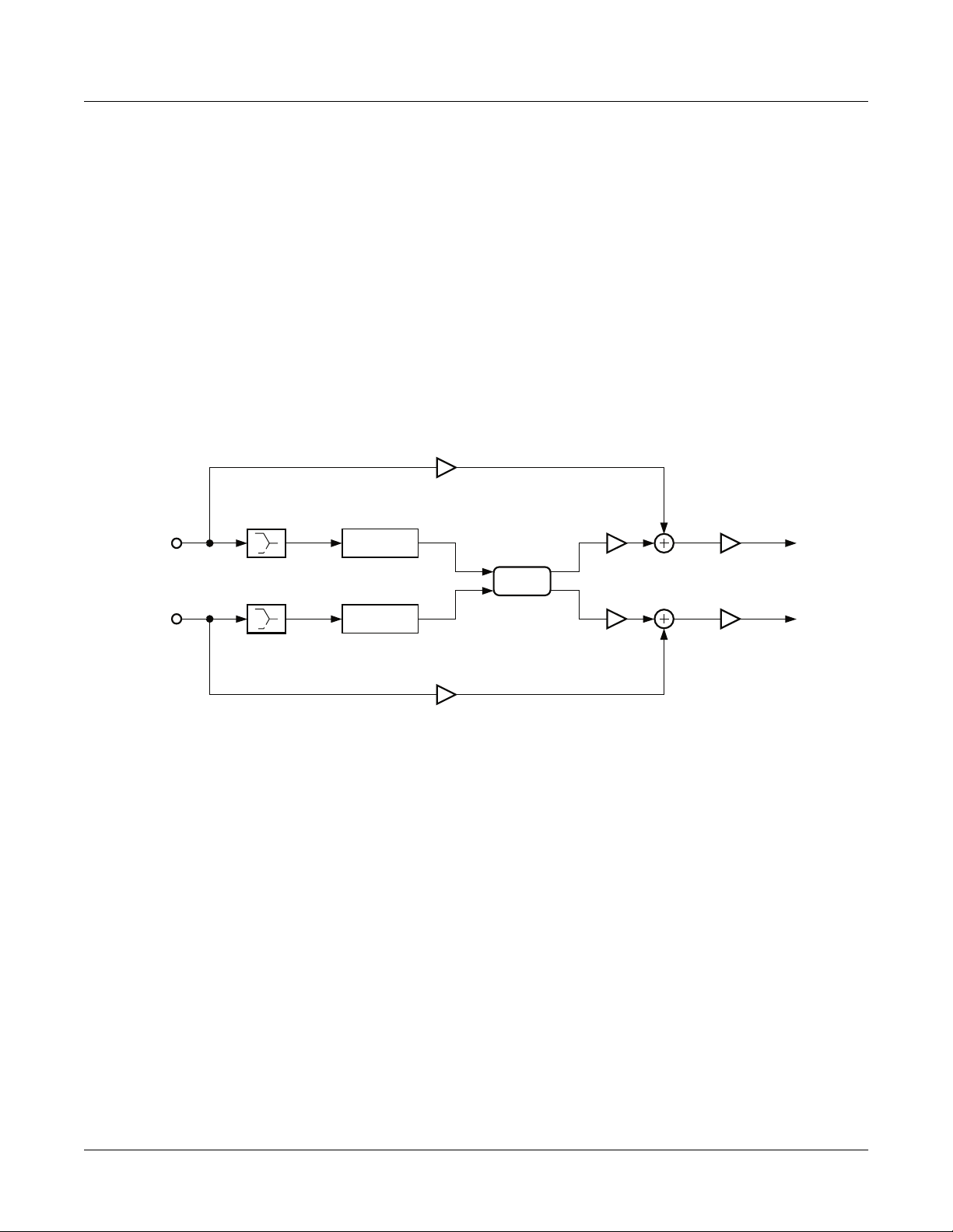
Complex Echo is an elaborate delay line with 3 independent output taps per channel, 2 independent
feedback taps per channel, equal power output tap panning, feedback diffuser, and high frequency
damping. Each channel has three ouptut taps which can each be delayed up to 2600ms (2.6 sec) then
panned at the output. Feedback taps can also be delayed up to 2600ms, but both feedback channels do
slightly different things. Feedback line 1 feeds the signal back to the delay input of the same channel, while
feedback line 2 feeds the signal back to the opposite channel. Feedback line 2 may also be referred to as a
Òping-pongÓ feedback. Relative levels for each feedback line can be set with the ÒFB2/FB1>FBÓ control
where 0% only allows FB1 to be used, and 100% only allows FB2 to be used.
The diffuser sits at the beginning of the delay line, and consists of three controls. Separate left and right
Diff Dly parameters control the length that a signal is smeared from 0 to 100ms as it passes through these
diffusers. Diff Amt adjusts the smearing intensity. Short diffuser delays can diffuse the sound while large
delays can drastically alter the spectral ßavor. Setting all three diffuser parameters to 0 disables the
diffuser.
10-28
Page 29
KDFX Reference
KDFX Algorithm Specifications
Also at the input to the delays are 1 pole (6dB/oct) lopass Þlters controlled by the HF Damping parameter.
L Tap Levels
Pan
Pan
L Input
Pan
Diffuser
Blend
Feedback FB2/FB1 > FB
Blend
Diffuser
Delay
FB1 FB2
Delay
R Input
Figure 10-6 Signal flow of Complex Echo
L Output
Out Gains
R Output
FB2FB1
Pan
Pan
Pan
R Tap Levels
Parameters
Page 1
Wet/Dry 0 to 100 %wet Out Gain Off, -79.0 to 24.0 dB
Feedback 0 to 100 % L Diff Dly 0 to 100 ms
FB2/FB1>FB 0 to 100 % R Diff Dly 0 to 100 ms
HF Damping 16 to 25088 Hz Diff Amt 0 to 100 %
Page 2
L Fdbk1 Dly 0 to 2600 ms R Fdbk1 Dly 0 to 2600 ms
L Fdbk2 Dly 0 to 2600 ms R Fdbk2 Dly 0 to 2600 ms
10-29
Page 30
KDFX Reference
KDFX Algorithm Specifications
L Tap1 Dly 0 to 2600 ms R Tap1 Dly 0 to 2600 ms
L Tap2 Dly 0 to 2600 ms R Tap2 Dly 0 to 2600 ms
L Tap3 Dly 0 to 2600 ms R Tap3 Dly 0 to 2600 ms
Page 3
L Tap1 Lvl 0 to 100 % R Tap1 Lvl 0 to 100 %
L Tap2 Lvl 0 to 100 % R Tap2 Lvl 0 to 100 %
L Tap3 Lvl 0 to 100 % R Tap3 Lvl 0 to 100 %
Page 4
L Tap1 Pan -100 to 100 % R Tap1 Pan -100 to 100 %
L Tap2 Pan -100 to 100 % R Tap2 Pan -100 to 100 %
L Tap3 Pan -100 to 100 % R Tap3 Pan -100 to 100 %
Wet/Dry The relative amount of input signal and effected signal that is to appear in the Þnal effect
output mix. When set to 0%, the output is taken only from the input (dry). When set to
100%, the output is all wet.
Out Gain The overall gain or amplitude at the output of the effect.
Feedback The amplitude of the feedback tap(s) fed back to the beginning of the delay.
FB2 / FB1>FB Balance control between feedback line 1 and line 2. 0% turns off feedback line 2 only
allowing use of feedback line 1. 50% is an even mix of both lines, and 100% turns off line 1.
HF Damping The amount of high frequency content of the signal to the input of the delay. This control
determines the cutoff frequency of the one-pole (-6dB/octave) lowpass Þlters.
Diff Dly Left and Right. Adjusts delay length of the diffusers.
Diff Amt Adjusts the diffuser intensity.
L Fdbk1 Dly Adjusts the delay length of the left channelÕs feedback tap fed back to the left channelÕs
delay input.
L Fdbk2 Dly Adjusts the delay length of the left channelÕs feedback tap fed back to the right channelÕs
delay input.
R Fdbk1 Dly Adjusts the delay length of the right channelÕs feedback tap fed back to the right channelÕs
delay input.
R Fdbk2 Dly Adjusts the delay length of the right channelÕs feedback tap fed back to the left channelÕs
delay input.
Ta p n Dly Left and Right. Adjusts the delay length of the left and right channelÕs three output taps.
Ta p n Lvl Left and Right. Adjusts the listening level of the left and right channelÕs three output taps.
10-30
Ta p n Pan Left and Right. Adjusts the equal power pan position of the left and right channelÕs three
output taps. 0% is center pan, negative values pan to left, and positive values pan to the
right.
Page 31

KDFX Reference
KDFX Algorithm Specifications
131 4-Tap Delay
132 4-Tap Delay BPM
A stereo four tap delay with feedback
PAUs: 1
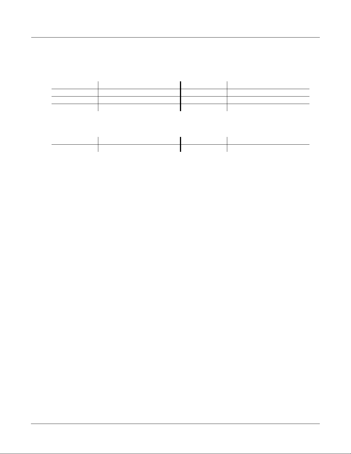
This is a simple stereo 4 tap delay algorithm with delay lengths deÞned in milliseconds (ms). The left and
right channels are fully symetric (all controls affect both channels). The duration of each stereo delay tap
(length of the delay) and the signal level from each stereo tap may be set. Prior to output each delay tap
passes through a level and left-right balance control. The taps are summed and added to the dry input
signal through a Wet/Dry control. The delayed signal from the ÒLoopÓ tap may be fed back to the delay
input.
Feedback
Input
High Freq
Damping
Dry
Figure 10-7 Left Channel of 4-Tap Delay
The delay length for any given tap is the sum of the coarse and Þne parameters for the tap multiplied by
the DelayScale parameter which is common to all taps. The DelayScale parameter allows you to change
the lengths of all the taps together.
Delay
Tap Levels
& Balance
Wet
Output
A repetitive loop delay is created by turning up the Fdbk Level parameter. Only the Loop tap is fed back to
the input of the delay, so this is the tap which controls the loop rate. Usually you will want the Loop delay
length to be longer than the other tap lengths. Set the Loop delay length to the desired length then set the
other taps to Þll in the measure with interesting rhythmical patterns. Setting tap levels allows some
ÒbeatsÓ to receive different emphasis than others. The delay lengths for 4-Tap Delay are in units of
milliseconds (ms). If you want to base delay lengths on tempo, then the 4-Tap Delay BPM algorithm may
be more convenient.
10-31
Page 32

KDFX Reference
KDFX Algorithm Specifications
The feedback (Fdbk Level) controls how long a sound in the delay line takes to die out. At 100% feedback,
your sound will be repeated indeÞnitely. HF Damping selectively removes high frequency content from
your delayed signal and will also cause your sound to eventually disappear.
The Hold parameter is a switch which controls signal routing. When turned on, Hold will play whatever
signal is in the delay line indeÞnitely. Hold overrides the feedback parameter and prevents any incoming
signal from entering the delay. You may have to practice using the Hold parameter. Each time your sound
goes through the delay, it is reduced by the feedback amount. If feedback is fairly low and you turn on
Hold at the wrong moment, you can get a disconcerting jump in level at some point in the loop. The Hold
parameter has no effect on the Wet/Dry or HF Damping parameters, which continue to work as usual, so
if there is some HF Damping, the delay will eventually die out.
See also the versions of these algorithms which specify delay lengths in terms of tempo and beats.
Parameters for Algorithm 131 4-Tap Delay
Page 1
Wet/Dry 0 to 100%wet Out Gain Off, -79.0 to 24.0 dB
Fdbk Level 0 to 100%
HF Damping 16 Hz to 25088 Hz Hold On or Off
Dry Bal -100 to 100%
Page 2
Loop Crs 0 to 2540 ms DelayScale 0.00x to 10.00x
Loop Fine -20 to 20 ms
Tap1 Crs 0 to 2540 ms Tap3 Crs 0 to 2540 ms
Tap1 Fine -20 to 20 ms Tap3 Fine -20 to 20 ms
Tap2 Crs 0 to 2540 ms Tap4 Crs 0 to 2540 ms
Tap2 Fine -20 to 20 ms Tap4 Fine -20 to 20 ms
Page 3
Loop Level 0 to 100 % Loop Bal -100 to 100 %
Tap2 Level 0 to 100 % Tap2 Bal -100 to 100 %
Tap3 Level 0 to 100 % Tap3 Bal -100 to 100 %
Tap4 Level 0 to 100 % Tap4 Bal -100 to 100 %
Wet/Dry The relative amount of input signal and delay signal that is to appear in the Þnal effect
output mix. When set to 0%, the output is taken only from the input (dry). When set to
100%, the output is all wet.
Out Gain The overall gain or amplitude at the output of the effect.
Fdbk Level The percentage of the delayed signal to feed back or return to the delay input. Turning up
the feedback will cause the effect to repeatedly echo or act as a crude reverb.
10-32
HF Damping The -3 dB frequency in Hz of a one pole lowpass Þlter (-6 dB/octave) placed in front of the
delay line. The Þlter is speciÞed for a signal passing through the Þlter once. Multiple
passes through the feedback will cause the signal to become more and more dull.
Page 33

KDFX Reference
KDFX Algorithm Specifications
Dry Bal The left-right balance of the dry signal. A setting of -100% allows only the left dry signal to
pass to the left output, while a setting of 100% lets only the right dry signal pass to the
right output. At 0%, equal amounts of the left and right dry signals pass to their respective
outputs.
Hold A switch which when turned on, locks any signal currently in the delay to play until Hold
is turned off. When Hold is on, no signal can enter the delay and Feedback is set to 100%
behind the scenes. Hold does not affect the HF Damping or Wet/Dry mix.
Loop Crs The coarse delay length of the Loop tap. If the feedback is turned up, this parameter sets
the repeating delay loop length. The resolution of the coarse adjust is 20 milliseconds, but
Þner resolution can be obtained using the Loop Fine parameter. The maximum delay
length is 2.55 seconds (2550ms) for the 4-Tap Delay.
Loop Fine A Þne adjustment to the Loop tap delay length. The delay resolution is 0.2 milliseconds
(ms). Loop Fine is added to Loop Crs (coarse) to get the actual delay length.
Tapn Crs The coarse delay lengths of the output taps (n = 1...4). The resolution of the coarse adjust
is 20 milliseconds, but Þner resolution can be obtained using the Tapn Fine parameters.
The maximum delay length is 2.55 seconds (2550ms) for the 4-Tap Delay.
Ta p n Fine A Þne adjustment to the output tap delay lengths (n = 1...4). The delay resolution is 0.2
milliseconds (ms). Tapn Fine is added to Tapn Crs (coarse) to get actual delay lengths.
Ta p n Level The amount of signal from each of the taps (n = 1...4) which get sent to the output. With
the Loop Lvl control, you can give different amounts of emphasis to various taps in the
loop.
Ta p n Bal The left-right balance of each of the stereo taps (n = 1...4). A setting of -100% allows only
the left tap to pass to the left output, while a setting of 100% lets only the right tap pass to
the right output. At 0%, equal amounts of the left and right taps pass to their respective
outputs.
Algorithm 132 4-Tap Delay BPM
In this Algorithm, the delay length for any given tap is determined by the tempo, expressed in beats per
minute (BPM), and the delay length of the tap expressed in beats (bts). The tempo alters all tap lengths
together. With the tempo in beats per minute and delay lengths in beats, you can calculate the length of a
delay in seconds as beats/tempo * 60 (sec/min). IMPORTANT NOTE: KDFX has a limited amount of
delay memory available (over 2.5 seconds for 4-Tap BPM). When slow tempos and/or long lengths are
speciÞed, you may run out of delay memory, at which point the delay length will be cut in half. When you
slow down the tempo, you may Þnd the delays suddently getting shorter.
A repetitive loop delay is created by turning up the feedback parameter (Fdbk Level). Only the Loop tap is
fed back to the input of the delay, so this is the tap which controls the loop rate. Usually you will want the
Loop tap (LoopLength parameter) to be longer than the other tap lengths. To repeat a pattern on a 4/4
measure (4 beats per measure) simply set LoopLength to 4 bts. The output taps can then be used to Þll in
the measure with interesting rhythmical patterns. Setting tap levels allows some ÒbeatsÓ to receive
different emphasis than others.
10-33
Page 34

KDFX Reference
KDFX Algorithm Specifications
Parameters
Page 1
Wet/Dry 0 to 100%wet Out Gain Off, -79.0 to 24.0 dB
Fdbk Level 0 to 100% Tempo System, 1 to 255 BPM
HF Damping 16 Hz to 25088 Hz Hold On or Off
Page 2
LoopLength 0 to 32 bts
Tap1 Delay 0 to 32 bts
Tap2 Delay 0 to 32 bts
Tap3 Delay 0 to 32 bts
Tap4 Delay 0 to 32 bts
Dry Bal -100 to 100%
Page 3
Tap1 Level 0 to 100 % Tap1 Bal -100 to 100 %
Tap2 Level 0 to 100 % Tap2 Bal -100 to 100 %
Tap3 Level 0 to 100 % Tap3 Bal -100 to 100 %
Tap4 Level 0 to 100 % Tap4 Bal -100 to 100 %
Tempo Basis for the delay lengths, as referenced to a musical tempo in bpm (beats per minute).
When this parameter is set to ÒSystemÓ, the tempo is locked to the internal sequencer
tempo or to incoming MIDI clocks. When it is set to ÒSystemÓ, sources (FUNs, LFOs, ASRs
etc.) will have no effect on the Tempo parameter.
LoopLength The delay length of the Loop tap. If the feedback is turned up, this parameter sets the
repeating delay loop length. LoopLength sets the loop delay length as a tempo beat
duration. The tempo is speciÞed with the Tempo parameter and the delay length is given
in beats (bts). The delay length in seconds is calculated as beats/tempo * 60 (sec/min).
Ta p n Delay The delay lengths of the taps (n = 1...4) as tempo beat durations. The tempo is speciÞed
with the Tempo parameter and the delay length is given in beats (bts). The delay length in
seconds is calculated as beats/tempo * 60 (sec/min). Use the output taps to create
interesting rhythmic patterns within the repeating loop.
10-34
Page 35

KDFX Reference
KDFX Algorithm Specifications
133 8-Tap Delay
134 8-Tap Delay BPM
A stereo eight tap delay with cross-coupled feedback
PAUs: 2
This is a simple stereo 8 tap delay algorithm with delay lengths deÞned in milliseconds (ms). The left and
right channels are fully symmetric (all controls affect both channels). The duration of each stereo delay tap
(length of the delay) and the signal level from each stereo tap may be set. Prior to output each delay tap
passes through a level and left-right balance control. Pairs of stereo taps are tied together with balance
controls acting with opposite left-right sense. The taps are summed and added to the dry input signal
throught a Wet/Dry control. The delayed signal from the ÒLoopÓ tap may be fed back to the delay input.
The sum of the input signal and the feedback signal may be mixed or swapped with the input/feedback
signal from the other channel (cross-coupling). When used with feedback, cross-coupling can achieve a
ping-pong effect between the left and right channels.
Feedback
Delay
L Input
From Right
Channel
To Right
Channel
High Freq
Damping
Top Levels
& Balance
Wet
L Output
Dry
Figure 10-8 Left Channel of 8-Tap Delay
The delay length for any given tap is the sum of the coarse and Þne parameters for the tap multiplied by
the DelayScale parameter which is common to all taps. The DelayScale parameter allows you to change
the lengths of all the taps together.
A repetitive loop delay is created by turning up the Fdbk Level parameter. Only the Loop tap is fed back to
the input of the delay, so this is the tap which controls the loop rate. Usually you will want the Loop delay
length to be longer than the other tap lengths. Set the Loop delay length to the desired length then set the
other taps to Þll in the measure with interesting rhythmical patterns. Setting tap levels allows some
ÒbeatsÓ to receive different emphasis than others. The delay lengths for 8-Tap Delay are in units of
milliseconds (ms). If you want to base delay lengths on tempo, then the 8-Tap Delay BPM algorithm may
be more convenient.
The feedback (Fdbk Level) controls how long a sound in the delay line takes to die out. At 100% feedback,
your sound will be repeated indeÞnitely. HF Damping selectively removes high frequency content from
your delayed signal and will also cause your sound to eventually disappear.
The Hold parameter is a switch which controls signal routing. When turned on, Hold will play whatever
signal is in the delay line indeÞnitely. Hold overrides the feedback parameter and prevents any incoming
10-35
Page 36

KDFX Reference
KDFX Algorithm Specifications
signal from entering the delay. You may have to practice using the Hold parameter. Each time your sound
goes through the delay, it is reduced by the feedback amount. If feedback is fairly low and you turn on
Hold at the wrong moment, you can get a disconcerting jump in level at some point in the loop. The Hold
parameter has no effect on the Wet/Dry or HF Damping parameters, which continue to work as usual, so
if there is some HF Damping, the delay will eventually die out.
See also the versions of these algorithms which specify delay lengths in terms of tempo and beats.
Parameters for Algorithm 133 8-Tap Delay
Page 1
Wet/Dry 0 to 100%wet Out Gain Off, -79.0 to 24.0 dB
Fdbk Level 0 to 100%
Xcouple 0 to 100% Dry Bal -100 to 100%
HF Damping 16 Hz to 25088 Hz Hold On or Off
Page 2
Loop Crs 0 to 5100 ms DelayScale 0.00x to 10.00x
Loop Fine -20 to 20 ms
Tap1 Crs 0 to 5100 ms Tap3 Crs 0 to 5100 ms
Tap1 Fine -20 to 20 ms Tap3 Fine -20 to 20 ms
Tap2 Crs 0 to 5100 ms Tap4 Crs 0 to 5100 ms
Tap2 Fine -20 to 20 ms Tap4 Fine -20 to 20 ms
Page 3
Tap5 Crs 0 to 5100 ms Tap7 Crs 0 to 5100 ms
Tap5 Fine -20 to 20 ms Tap7 Fine -20 to 20 ms
Tap6 Crs 0 to 5100 ms Tap8 Crs 0 to 5100 ms
Tap6 Fine -20 to 20 ms Tap8 Fine -20 to 20 ms
Page 4
Tap1 Level 0 to 100 % Tap5 Level 0 to 100 %
Tap2 Level 0 to 100 % Tap6 Level 0 to 100 %
Tap3 Level 0 to 100 % Tap7 Level 0 to 100 %
Tap4 Level 0 to 100 % Tap8 Level 0 to 100 %
Tap1/-5Bal -100 to 100 % Tap3/-7Bal -100 to 100 %
Tap2/-6Bal -100 to 100 % Tap4/-8Bal -100 to 100 %
Wet/Dry The relative amount of input signal and delay signal that is to appear in the Þnal effect
output mix. When set to 0%, the output is taken only from the input (dry). When set to
100%, the output is all wet.
Out Gain The overall gain or amplitude at the output of the effect.
10-36
Page 37

KDFX Reference
KDFX Algorithm Specifications
Fdbk Level The percentage of the delayed signal to feed back or return to the delay input. Turning up
the feedback will cause the effect to repeatedly echo or act as a crude reverb.
Xcouple 8 Tap Delay is a stereo effect. The cross coupling control lets you send the feedback from a
channel to its own input (0% cross coupling) or to the other channelÕs input (100% cross
coupling) or somewhere in between. This control has no effect if the Fdbk Level control is
set to 0%.
HF Damping The -3 dB frequency in Hz of a one pole lowpass Þlter (-6 dB/octave) placed in front of the
delay line. The Þlter is speciÞed for a signal passing through the Þlter once. Multiple
passes through the feedback will cause the signal to become more and more dull.
Dry Bal The left-right balance of the dry signal. A setting of -100% allows only the left dry signal to
pass to the left output, while a setting of 100% lets only the right dry signal pass to the
right output. At 0%, equal amounts of the left and right dry signals pass to their respective
outputs.
Hold A switch which when turned on, locks any signal currently in the delay to play until Hold
is turned off. When Hold is on, no signal can enter the delay and Feedback is set to 100%
behind the scenes. Hold does not affect the HF Damping or Wet/Dry mix.
Loop Crs The coarse delay length of the Loop tap. If the feedback is turned up, this parameter sets
the repeating delay loop length. The resolution of the coarse adjust is 20 milliseconds, but
Þner resolution can be obtained using the Loop Fine parameter. The maximum delay
length is 5.10 seconds (5100ms) for the 8-Tap Delay.
Loop Fine A Þne adjustment to the Loop tap delay length. The delay resolution is 0.2 milliseconds
(ms). Loop Fine is added to Loop Crs (coarse) to get the actual delay length.
Ta p n Crs The coarse delay lengths of the output taps (n = 1...8). The resolution of the coarse adjust
is 20 milliseconds, but Þner resolution can be obtained using the Tapn Fine parameters.
The maximum delay length is 5.1 seconds (5100ms) for the 8-Tap Delay.
Ta p n Fine A Þne adjustment to the output tap delay lengths (n = 1...8). The delay resolution is 0.2
milliseconds (ms). Tapn Fine is added to Tapn Crs (coarse) to get actual delay lengths.
Ta p n Level The amount of signal from each of the taps (n = 1...8) which get sent to the output.
Ta p m/ - n Bal The left-right balance of each of the stereo taps. The balances are controlled in pairs of
taps: 1 & 5, 2 & 6, 3 & 7, and 4 & 8. The balance controls work in opposite directions for the
two taps in the pair. When the balance is set to -100%, the Þrst tap of the pair is fully right
while the second is fully left. At 0%, equal amounts of the left and right taps pass to their
respective outputs.
Algorithm 134: 8-Tap Delay BPM
In this Algorithm the delay length for any given tap is determined by the tempo, expressed in beats per
minute (BPM), and the delay length of the tap expressed in beats (bts). The tempo alters all tap lengths
together. With the tempo in beats per minute and delay lengths in beats, you can calculate the length of a
delay in seconds as beats/tempo * 60 (sec/min). IMPORTANT NOTE: KDFX has a limited amount of
delay memory available (over 5 seconds for 8 Tap Delay BPM). When slow tempos and/or long lengths
are speciÞed, you may run out of delay memory, at which point the delay length will be cut in half. When
you slow down the tempo, you may Þnd the delays suddenly getting shorter.
A repetitive loop delay is created by turning up the feedback parameter (Fdbk Level). Only the Loop tap is
fed back to the input of the delay, so this is the tap which controls the loop rate. Usually you will want the
Loop tap (LoopLength parameter) to be longer than the other tap lengths. To repeat a pattern on a 4/4
measure (4 beats per measure) simply set LoopLength to 4 bts. The output taps can then be used to Þll in
10-37
Page 38

KDFX Reference
KDFX Algorithm Specifications
the measure with interesting rhythmical patterns. Setting tap levels allows some ÒbeatsÓ to receive
different emphasis than others.
Parameters
Page 1
Wet/Dry 0 to 100%wet Out Gain Off, -79.0 to 24.0 dB
Fdbk Level 0 to 100% Tempo System, 1 to 255 BPM
Xcouple 0 to 100% Dry Bal -100 to 100%
HF Damping 16 Hz to 25088 Hz Hold On or Off
Page 2
LoopLength 0 to 32 bts
Tap1 Delay 0 to 32 bts Tap5 Delay 0 to 32 bts
Tap2 Delay 0 to 32 bts Tap6 Delay 0 to 32 bts
Tap3 Delay 0 to 32 bts Tap7 Delay 0 to 32 bts
Tap4 Delay 0 to 32 bts Tap8 Delay 0 to 32 bts
Page 3
Tap1 Level 0 to 100 % Tap5 Level 0 to 100 %
Tap2 Level 0 to 100 % Tap6 Level 0 to 100 %
Tap3 Level 0 to 100 % Tap7 Level 0 to 100 %
Tap4 Level 0 to 100 % Tap8 Level 0 to 100 %
Page 4
Tap1 Bal -100 to 100 % Tap5 Bal -100 to 100 %
Tap2 Bal -100 to 100 % Tap6 Bal -100 to 100 %
Tap3 Bal -100 to 100 % Tap7 Bal -100 to 100 %
Tap4 Bal -100 to 100 % Tap8 Bal -100 to 100 %
Tempo Basis for the delay lengths, as referenced to a musical tempo in bpm (beats per minute).
When this parameter is set to ÒSystemÓ, the tempo is locked to the internal sequencer
tempo or to incoming MIDI clocks. When it is set to ÒSystemÓ, sources (FUNs, LFOs, ASRs
etc.) will have no effect on the Tempo parameter.
LoopLength The delay length of the Loop tap. If the feedback is turned up, this parameter sets the
repeating delay loop length. LoopLength sets the loop delay length as a tempo beat
duration. The tempo is speciÞed with the Tempo parameter and the delay length is given
in beats (bts). The delay length in seconds is calculated as beats/tempo * 60 (sec/min).
10-38
Ta p n Delay The delay lengths of the taps (n = 1...8) as tempo beat durations. The tempo is speciÞed
with the Tempo parameter and the delay length is given in beats (bts). The delay length in
seconds is calculated as beats/tempo * 60 (sec/min). Use the output taps to create
interesting rhythmic patterns within the repeating loop.
Page 39

KDFX Reference
KDFX Algorithm Specifications
135 Spectral 4-Tap
136 Spectral 6-Tap
Tempo based 4 and 6 tap delays with added shapers and resonant comb filters on each tap
PAUs: 2 for Spectral 4-Tap
3 for Spectral 6-Tap
Spectral 4 Tap and Spectral 6 Tap are respectively 2 and 3 processing allocation unit (PAU) tempo based
multi-tap delay effects. They are similar to a simple 4 and 6 tap delays with feedback, but have their
feedback and output taps modiÞed with shapers and Þlters. In the feedback path of each are a diffuser,
hipass Þlter, lopass Þlter, and imager. Each delay tap has a shaper, comb Þlter, balance and level controls
with the exception of Tap 1, which does not have a comb Þlter (Figure 1).
Diffusers add a quality that can be described as ÒsmearingÓ the feedback signal. The more a signal has
been regenerated through feedback and consequently fed through the diffuser, the more it is smeared. It
requires two parameters, one for the duration a signal is smeared labeled Diff Delay, and the other for the
amount it is smeared labeled Diff Amt. Positive diffusion settings will add diffusion while maintaining
image integrity. Negative diffusion amounts will cause the feedback image to lose image integrity and
become wide. Short Diff Delay settings have subtle smearing effects. Increasing Diff Delay will be more
noticeable, and long delay settings will take on a ringy resonant quality. To disable the diffuser, both Diff
Delay and Diff Amt should be set to zero.
Two 1 pole 6dB/oct Þlters are also in the feedback path: hipass and lopass. The hipass Þlter roll-off
frequency is controlled with LF Damping, and the lopass Þlter roll-off frequency is controlled by HF
Damping.
The imager (found on PARAM2) shifts the stereo input image when fed through feedback. Small positive
or negative values shift the image to the right or left respectively. Larger values shift the image so much
that the image gets scrambled through each feedback generation.
On each output tap is a shaper. For an overview of shaper functionality, refer to the section on shapers in
the MusicianÕs Guide. The Spectral Multi-Tap shapers offer 4 shaping loops as opposed to 8 found in the
VAST shapers, but can allow up to 6.00x intensity (Figure 2). Immediately following the shapers on taps 2
and above are resonant comb Þlters tuned in semitones. These comb Þlters make the taps become pitched.
When a comb Þlter is in use, the shaper before it can be used to intensify these pitched qualities.
Each tap also has separate balance and level controls.
Since these are tempo based effects, tap delay values and feedback delay (labeled LoopLength on
PARAM2) values are set relative to a beat. The beat duration is set be adjusting Tempo in BPM. The tempo
can be synced to the system clock by setting Tempo to System. Each tapÕs delay is adjusted relative to 1
beat, in 1/24 beat increments. Notice that 24 is a musically useful beat division because it can divide a beat
into halves, 3rds, 4ths, 6ths, 8ths, 12ths, and of course 24ths. For example, setting LoopLength to Ò1 12/
24btsÓ will put the feedback tap at 1 1/2 beats (dotted quarter note in 4/4 time) of delay making the
feedback repetition occur every one and a half beats. This is equivalent to 3/4 of a second at 120 BPM.
10-39
Page 40

KDFX Reference
KDFX Algorithm Specifications
When Temp is set to 60 BPM, each 1/24th of a beat is equivalent to 1/24th of a second. When tempo is set
to 250 BPM, each 1/24th of a beat is equivalent to 10ms of delay.
L Dry
L Input
R Input
Diffuser
Diffuser
Imaging
Shaper
(Individual Shaper, Comb
and Gain for Taps 2-6)
Comb
Delay
Delay
(Individual Shaper, Comb
and Gain for Taps 2-6)
Shaper
Comb
L Output
Shaper
Tap 1
Feedback
Tap 1
Shaper
R Output
10-40
R Dry
Figure 10-9 Spectral 6 Tap
Page 41

KDFX Algorithm Specifications
0.20x0.10x 0.50x
KDFX Reference
1.00x 2.00x 6.00x
Figure 10-10 Various shaper curves used in the Spectral Multi-Taps
Parameters for Spectral 4-Tap
Page 1
Wet/Dry 0 to 100 % Out Gain Off, -79.0 to 24.0 dB
Fdbk Level 0 to 100 % Tempo System, 0 to 255 BPM
HF Damping 16 to 25088 Hz Diff Delay 0 to 20.0 ms
LF Damping 16 to 25088 Hz Diff Amt -100 to 100 %
Page 2
LoopLength On or Off Tap2 Delay 0 to 32 bts
Fdbk Image -100 to 100 % Tap2 Shapr 0.10 to 6.00 x
Tap1 Delay 0 to 32 bts Tap2 Pitch C-1 to C8
Tap1 Shapr 0.10 to 6.00 x Tap2 PtAmt 0 to 100%
Tap1 Level 0 to 100 % Tap2 Level 0 to 100%
Tap1 Bal -100 to 100 % Tap2 Bal -100 to 100%
10-41
Page 42

KDFX Reference
KDFX Algorithm Specifications
Page 3
Tap3 Delay 0 to 32 bts Tap4 Delay 0 to 32 bts
Tap3 Shapr 0.10 to 6.00 x Tap4 Shapr 0.10 to 6.00 x
Tap3 Pitch C-1 to C8 Tap4 Pitch C-1 to C8
Tap3 PtAmt 0 to 100% Tap4 PtAmt 0 to 100%
Tap3 Level 0 to 100% Tap4 Level 0 to 100%
Tap3 Bal -100 to 100% Tap4 Bal -100 to 100%
Parameters for Spectral 6-Tap
Page 1
Wet/Dry 0 to 100 % Out Gain Off, -79.0 to 24.0 dB
Fdbk Level 0 to 100 % Tempo System, 0 to 255 BPM
HF Damping 16 to 25088 Hz Diff Delay 0 to 20.0 ms
LF Damping 16 to 25088 Hz Diff Amt -100 to 100 %
Page 2
LoopLength On or Off Tap2 Delay 0 to 32 bts
Fdbk Image -100 to 100 % Tap2 Shapr 0.10 to 6.00 x
Tap1 Delay 0 to 32 bts Tap2 Pitch C-1 to C8
Tap1 Shapr 0.10 to 6.00 x Tap2 PtAmt 0 to 100%
Tap1 Level 0 to 100 % Tap2 Level 0 to 100%
Tap1 Bal -100 to 100 % Tap2 Bal -100 to 100%
Page 3
Tap3 Delay 0 to 32 bts Tap4 Delay 0 to 32 bts
Tap3 Shapr 0.10 to 6.00 x Tap4 Shapr 0.10 to 6.00 x
Tap3 Pitch C-1 to C8 Tap4 Pitch C-1 to C8
Tap3 PtAmt 0 to 100% Tap4 PtAmt 0 to 100%
Tap3 Level 0 to 100% Tap4 Level 0 to 100%
Tap3 Bal -100 to 100% Tap4 Bal -100 to 100%
Page 4
Tap5 Delay 0 to 32 bts Tap6 Delay 0 to 32 bts
Tap5 Shapr 0.10 to 6.00 x Tap6 Shapr 0.10 to 6.00 x
Tap5 Pitch C-1 to C8 Tap6 Pitch C-1 to C8
Tap5 PtAmt 0 to 100% Tap6 PtAmt 0 to 100%
Tap5 Level 0 to 100% Tap6 Level 0 to 100%
Tap5 Bal -100 to 100% Tap6 Bal -100 to 100%
10-42
Page 43

KDFX Reference
KDFX Algorithm Specifications
Wet/Dry The relative amount of input signal and effected signal that is to appear in the Þnal effect
output mix. When set to 0%, the output is taken only from the input (dry). When set to
100%, the output is all wet. Negative values polarity invert the wet signal.
Out Gain The overall gain or amplitude at the output of the effect.
Fdbk Level The amount that the feedback tap is fed to the input of the delay.
HF Damping The amount of high frequency content of the signal to the input of the delay. This control
determines the cutoff frequency of the one-pole (-6dB/octave) lopass Þlters.
LF Damping The amount of low frequency content of the signal to the input of the delay. This control
determines the cutoff frequency of the one-pole (-6dB/octave) lopass Þlters.
Tempo Basis for the rates of the delay times, as referenced to a musical tempo in BPM (beats per
minute). When this parameter is set to ÒSystemÓ, the tempo is locked to the internal
sequencer tempo or to incoming MIDI clocks. When it is set to ÒSystemÓ, sources (FUNs,
LFOs, ASRs etc.) will have no effect on the Tempo parameter.
Diff Dly The length that the diffuser smears the signal sent to the input of the delay.
Diff Amt The intensity that the diffuser smears the signal sent to the input of the delay. Negative
values decorrelate the stereo signal.
LoopLength The delay length of the feedback tap in 24ths of a beat.
Fdbk Image Sets the amount the stereo image is shifted each time it passes through the feedback line.
Tap n Delay Adjusts the length of time in 24ths of a beat each output tap is delayed.
Tap n Shapr Adjusts the intensity of the shaper at each output tap.
Tap n Pitch Adjusts the frequency in semitones of the comb Þlter at each output tap.
Tap n PtAmt Adjusts the intensity of the comb Þlter at each output tap.
Tap n Level Adjusts the relative amplitude that each output tap is heard.
Tap n Bal Adjusts the left/right balance of each output tap. Negative values bring down the right
channel, and positive values bring down the left channel.
10-43
Page 44

KDFX Reference
KDFX Algorithm Specifications
Algorithms 150–153: Choruses
150 Chorus 1
151 Chorus 2
152 Dual Chorus 1
153 Dual Chorus 2
One and three tap dual mono choruses
PAUs: 1 for Chorus 1 (both)
2 for Chorus 2 (both)
Chorus is an effect that gives the illusion of multiple voices playing in unison. The effect is achieved by
detuning copies of the original signal and summing the detuned copies back with the original. Low
frequency oscillators (LFOs) are used modulate the positions of output taps from a delay line. The delay
line tap modulation causes the pitch of the signal to shift up and down, producing the required detuning.
The choruses are available as stereo or dual mono. The stereo choruses have the parameters for the left
and right channels ganged.
F
Dry
Feedback
Delay
L Input
High Freq
Damping
From Right
Channel
Figure 10-11 Block diagram of left channel of Chorus 2
Right channel is the same.
To Right
Channel
Tap Levels
Wet
L Output
10-44
Page 45

KDFX Reference
KDFX Algorithm Specifications
Chorus 2 is a 2 unit allocation multi-tapped delay (3 taps) based chorus effect with cross-coupling and
individual output tap panning. Figure 10-11 is a simpliÞed block diagram of the left channel of Chorus 2.
Dry
Feedback
L Input
Delay
High Freq
Damping
From Right
Channel
To Right
Channel
Figure 10-12 Block Diagram of Left Channel of Dual Chorus 2 (right channel is similar)
The dual mono choruses are like the stereo choruses but have separate left and right controls. Dual mono
choruses also allow you to pan the delay taps between left or right outputs
Dry
Tap Levels
Pan
Pan
Pan
Wet
Wet
From Right
Pans
To Right
Output Sum
L Output
Feedback
Delay
L Input
High Freq
Damping
Tap Level
From Right
Channel
Figure 10-13 Block diagram of left channel of Chorus 1 (right channel is the same)
To Right
Channel
Wet
L Output
10-45
Page 46

KDFX Reference
KDFX Algorithm Specifications
Chorus 1 uses just 1 unit allocation and has one delay tap. Figure 10-13 is a simpliÞed block diagram of the
left channel of Chorus 1.
Dry
Feedback
L Input
Delay
High Freq
Damping
Tap Level Wet
From Right
Channel
Figure 10-14 Block diagram of left channel of Dual Chorus 1 (right channel is similar)
The left and right channels pass through their own chorus blocks and there may be cross-coupling
between the channels. For Chorus 2 and Dual Chorus 2, each channel has three moving taps which are
summed, while Chorus 1 and Dual Chorus 2 have one moving tap for both channels. For the dual mono
choruses you can pan the taps to left or right. The summed taps (or the single tap of Chorus 1) is used for
the wet output signal. The summed tap outputs, weighted by their level controls, are used for feedback
back to the delay line input. The input and feedback signals go through a one pole lowpass Þlter (HF
Damping) before going entering the delay line.
To Right
Channel
Pan
Wet
From Right
Pans
To Right
Output Sum
L Output
10-46
The Wet/Dry control is an equal power crossfade. Note that the Output Gain parameters affects both wet
and dry signals.
For each of the LFO tapped delay lines, you may set the tap levels, the left/right pan position, delays of the
modulating delay lines, the rates of the LFO cycles, and the maximum depths of the pitch detuning. The
LFOs detune the pitch of signal copies above and below the original pitch. The depth units are in cents, and
there are 100 cents in a semitone.
Page 47

KDFX Reference
KDFX Algorithm Specifications
In the stereo Chorus 1 and Chorus 2, the relative phases of the LFOs modulating the left and right channels
may be adjusted.
Range of LFO
Delay Input
Shortest
Delay
Tap Dly
Center
of LFO
LFO Xcurs LFO Xcurs
Longest
Delay
Figure 10-15 Delay for a Single LFO
The settings of the LFO rates and the LFO depths determine how far the LFOs will sweep across their
delay lines from the shortest delays to the longest delays (the LFO excursions). The Tap Delays specify the
average amount of delay of the LFO modulated delay lines, or in other words the delay to the center of the
LFO excursion. The center of LFO excursion can not move smoothly. Changing the center of LFO
excursion creates discontinuities in the tapped signal. It is therefore a good idea to adjust the Tap Dly
parameter to a reasonable setting (one which gives enough delay for the maximum LFO excursion), then
leave it. Modulating Tap Dly will produce unwanted zipper noise. If you increase the LFO modulation
depth or reduce the LFO rate to a point where the LFO excursion exceeds the speciÞed Tap Dly, the center
of LFO excursion will be moved up, and again cause signal discontinuities. However, if enough Tap Dly is
speciÞed, Depth and Rate will be modulated smoothly.
As the LFOs sweep across the delay lines, the signal will change pitch. The pitch will change with a
triangular envelope (rise-fall-rise-fall) or with a trapezoidal envelope (rise-hold-fall-hold). You can choose
the pitch envelope with the Pitch Env parameter. Unfortunately rate and depth cannot be smoothly
modulated when set to the ÒTrapzoidÓ setting.
Pit ch
Time Time
(i)
Figure 10-16 Pitch Envelopes (i) Triangle and (ii) Trapzoid
Parameters for Chorus 1
Page 1
Wet/Dry -100 to 100%wet Out Gain Off, -79.0 to 24.0 dB
Fdbk Level -100 to 100%
Xcouple 0 to 100%
HF Damping 16 Hz to 25088 Hz Pitch Env Triangle or Trapzoid
(ii)
10-47
Page 48

KDFX Reference
KDFX Algorithm Specifications
Page 2
Tap Lvl -100 to 100% LFO Rate 0.01 to 10.00 Hz
Tap Dly 0.0 to 1000.0 ms LFO Depth 0.0 to 50.0 ct
Parameters for Chorus 2
Page 1
Wet/Dry -100 to 100%wet Out Gain Off, -79.0 to 24.0 dB
Fdbk Level -100 to 100%
Xcouple 0 to 100%
HF Damping 16 Hz to 25088 Hz Pitch Env Triangle or Trapzoid
Page 2
Tap1 Lvl -100 to 100 % Tap1 Dly 4.0 to 1000.0 ms
Tap2 Lvl -100 to 100 % Tap2 Dly 4.0 to 1000.0 ms
Tap3 Lvl -100 to 100 % Tap3 Dly 4.0 to 1000.0 ms
L/R Phase 0.0 to 360.0 deg
Page 3
LFO1 Rate 0.01 to 10.00 Hz LFO1 LRPhs 0.0 to 360.0 deg
LFO2 Rate 0.01 to 10.00 Hz LFO2 LRPhs 0.0 to 360.0 deg
LFO3 Rate 0.01 to 10.00 Hz LFO3 LRPhs 0.0 to 360.0 deg
LFO1 Dpth 0.0 to 50.0 ct
LFO2 Dpth 0.0 to 50.0 ct
LFO3 Dpth 0.0 to 50.0 ct
Parameters for Dual Chorus 1
Page 1
L Wet/Dry -100 to 100%wet R Wet/Dry -100 to 100%wet
L Out Gain Off, -79.0 to 24.0 dB R Out Gain Off, -79.0 to 24.0 dB
L Fdbk Lvl -100 to 100% R Fdbk Lvl -100 to 100%
Xcouple 0 to 100%
Page 2
L Tap Lvl -100 to 100% R Tap Lvl -100 to 100%
L Tap Pan -100 to 100% R Tap Pan -100 to 100%
L LFO Rate 0.01 to 10.00 Hz R LFO Rate 0.01 to 10.00 Hz
L LFODepth 0.0 to 50.0 ct R LFO Depth 0.0 to 50.0 ct
L Tap Dly 0.0 to 1000.0 ms R Tap Dly 0.0 to 1000.0 ms
L HF Damp 16 Hz to 25088 Hz R HF Damp 16 Hz to 25088 Hz
10-48
Page 49

KDFX Algorithm Specifications
Page 3
L PitchEnv Triangle or Trapzoid R PitchEnv Triangle or Trapzoid
Parameters for Dual Chorus 2
Page 1
L Wet/Dry -100 to 100%wet R Wet/Dry -100 to 100%wet
L Out Gain Off, -79.0 to 24.0 dB R Out Gain Off, -79.0 to 24.0 dB
L Fdbk Lvl -100 to 100% R Fdbk Lvl -100 to 100%
Xcouple 0 to 100%
Page 2
L Tap1 Lvl -100 to 100 % R Tap1 Lvl -100 to 100 %
L Tap2 Lvl -100 to 100 % R Tap2 Lvl -100 to 100 %
L Tap3 Lvl -100 to 100 % R Tap3 Lvl -100 to 100 %
L Tap1 Pan -100 to 100 % R Tap1 Pan -100 to 100 %
L Tap2 Pan -100 to 100 % R Tap2 Pan -100 to 100 %
L Tap3 Pan -100 to 100 % R Tap3 Pan -100 to 100 %
KDFX Reference
Page 3
L LFO1Rate 0.01 to 10.00 Hz R LFO1Rate 0.01 to 10.00 Hz
L LFO2Rate 0.01 to 10.00 Hz R LFO2Rate 0.01 to 10.00 Hz
L LFO3Rate 0.01 to 10.00 Hz R LFO3Rate 0.01 to 10.00 Hz
L LFO1Dpth 0.0 to 50.0 ct R LFO1Dpth 0.0 to 50.0 ct
L LFO2Dpth 0.0 to 50.0 ct R LFO2Dpth 0.0 to 50.0 ct
L LFO3Dpth 0.0 to 50.0 ct R LFO3Dpth 0.0 to 50.0 ct
Page 4
L Tap1 Dly 0.0 to 1000.0 ms R Tap1 Dly 0.0 to 1000.0 ms
L Tap2 Dly 0.0 to 1000.0 ms R Tap2 Dly 0.0 to 1000.0 ms
L Tap3 Dly 0.0 to 1000.0 ms R Tap3 Dly 0.0 to 1000.0 ms
L HF Damp 16 Hz to 25088 Hz R HF Damp 16 Hz to 25088 Hz
L PitchEnv Triangle or Trapzoid R PitchEnv Triangle or Trapzoid
Wet/Dry The relative amount of input (dry) signal and chorus (wet) signal that is to appear in the
Þnal effect output mix. When set to 0%, the output is taken only from the input. When set
to 100%, the output is all wet. Negative values polarity invert the wet signal.
Out Gain The overall gain or amplitude at the output of the effect.
Fdbk Level The level of the feedback signal into the delay line. The feedback signal is taken from the
LFO1 delay tap. Negative values polarity invert the feedback signal.
10-49
Page 50

KDFX Reference
KDFX Algorithm Specifications
Xcouple Controls how much of the left channel input and feedback signals are sent to the right
channel delay line and vice versa. At 50%, equal amounts from both channels are sent to
both delay lines. At 100%, the left feeds the right delay and vice versa.
HF Damping The amount of high frequency content of the signal that is sent into the delay lines. This
control determines the cutoff frequency of the one-pole (-6dB/octave) lowpass Þlter.
Pitch Env The pitch of the chorus modulation can be made to follow a triangular ÒTriangleÓ
envelope (rise-fall-rise-fall) or a trapezoidal ÒTrapzoidÓ envelope (rise-hold-fall-hold).
Tap Lvl Levels of the LFO modulated delay taps. Negative values polarity invert the signal.
Setting any tap level to 0% effectively turns off the delay tap. Since these controls allow
the full input level to pass through all the delay taps, a 100% setting on all the summed
taps will signiÞcantly boost the wet signal relative to dry. A 50% setting may be more
reasonable.
Tap Pan The left or right output panning of the delay taps. The range is -100% for fully left to 100%
for fully right. Setting the pan to 0% sends equal amounts to both left and right channels
for center or mono panning. [Dual Chorus 1 & 2 only]
LFO Rate Used to set the speeds of modulation of the delay lines. Low rates increase LFO excursion
(see LFO Dpth below). If Pitch Env is set to ÒTrapzoidÓ, you will be unable to put the rate
on an FXMod or otherwise change the rate without introducing discontinuities (glitches
or zippering) to your output signal. The triangular ÒTriangleÓ Pitch Env setting does allow
smooth rate modulation, provided youÕve speciÞed enough delay.
LFO Depth The maximum depths of detuning of the LFO modulated delay lines. The depth controls
range from 0 to 50 cents. (There are 100 cents in a semitone.) If you do not have enough
delay speciÞed with Tap Dly to get the depth youÕve dialed up, then Tap Dly will be
forced to increase (with signal disconinuities if signal is present). The LFOs move a tap
back and forth across the delay lines to shift the pitch of the tapped signal. The maximum
distance the taps get moved from the center position of the LFO is called the LFO
excursion. Excursion is calculated from both the LFO depth and rate settings. Large
depths and low rates produce large excursions. If Pitch Env is set to ÒTrapzoidÓ, you will
be unable to put the depth on an FXMod or otherwise change the depth without
introducing discontinuities (glitches or zippering) to your output signal. The triangular
ÒTriangleÓ Pitch Env setting does allow smooth depth modulation, provided youÕve
speciÞed enough delay.
Tap Dly The average delay length, or the delay to the center of the LFO sweep. If the delay is
shorter than the LFO excursion, then the Tap Dly will be forced to a longer length equal to
the amount of required excursion (the parameter display will not change though).
Changing this parameter while signal is present will cause signal discontinuities. ItÕs best
to set and forget this one. Set it long enough so that there are no discontinuities with the
largest Depth and lowest Rates that you will be using.
L/R Phase (Or LFOn LRPhs) In the stereo Chorus 1 and Chorus 2, the relative phases of the LFOs for
the left and right channels may be adjusted.
10-50
Page 51

L Input
KDFX Reference
KDFX Algorithm Specifications
154 Flanger 1
155 Flanger 2
Multi-tap flangers
PAUs: 1 for Flanger 1
2 for Flanger 2
Flanger 1 is a 1 processing allocation unit (PAU) multi-sweep Thru-zero ßanger effect with two LFOs per
channel.
Dry
Delay
From Right
Channel
High Freq
Damping
To Right
Channel
LFO
Tap
Levels
Static
Tap
Level
L Output
Feedback
Wet
Out Gain
Figure 10-17 Simplified block diagram of the left channel of Flanger 1 (right channel is similar)
10-51
Page 52

KDFX Reference
KDFX Algorithm Specifications
Flanger 2 is a 2 processing allocation unit (PAU) multi-sweep Thru-zero ßanger effect with two LFOs per
channel.
Noise
L Input
Dry
Delay
From Right
Channel
High Freq
Damping
To Right
Channel
LFO Feedback
Static Tap Feedback
LFO
Tap
Levels
Static
Tap
Level
Wet
L Output
Out Gain
Figure 10-18 Simplified block diagram of the left channel of Flanger 2 (right channel is similar)
Flanging was originally created by summing the outputs of two un-locked tape machines while varying
their sync by pressing a hand to the outside edge of one reel, thus the historic name reel-ßanging. The key
to achieving the ßanging effect is the summing of a signal with a time-displaced replica of itself.
Adding or subtracting a signal with a time-displaced replica of itself results in a series of notches in the
frequency spectrum. These notches are equally spaced in (linear) frequency at multiples whose
wavelengths are equal to the time delay. The result is generally referred to as a comb Þlter (the name
arising from the resemblance of the spectrum to a comb). See Figure 10-18. If the levels of the signals being
added or subtracted are the same, the notches will be of inÞnite depth (in dB) and the peaks will be up 6
dB. Flanging is achieved by time-varying the delay length, thus changing the frequencies of the notches.
The shorter the delay time, the greater the notch separation. This delay time variation imparts a sense of
motion to the sound. Typically the delay times are on the order of 0-5 ms. Longer times begin to get into
10-52
Page 53

KDFX Reference
KDFX Algorithm Specifications
the realm of chorusing, where the ear begins to perceive the audio output as nearly two distinct signals,
but with a variable time displacement.
10
Amp
(dB)
0
10
20
Frequency
Figure 10-19 Comb Filters : Solid Line for Addition; Dashed Line for Subtraction
The heart of the ßanger implemented here is a multi-tap delay line. You can set the level of each tap as a
percentage of the input level, and the level may be negative (phase inverting). One tap is a simple static
delay over which you can control the length of delay (from the input tap). Four of the taps can have their
lengths modulated up and down by a low frequency oscillator (LFO). You are given control of the rate of
the LFOs, how far each LFO can sweep through the delay line, and the relative phases of the LFOs. (i.e.
Where is the LFO in its sweep: going away from the input tap or coming toward it?)
The ßanger uses tempo units (based on the sequencer tempo or MIDI clock if you like), together with the
number of tempo beats per LFO cycle. Thus if the tempo is 120 bpm (beats per minute) and the LFO Period
is set to 1, the LFOs will pass through 120 complete cycles in a minute or 2 cycles per second (2 Hz).
Increasing the LFO Period increases the period of the LFOs (slows them down). An LFO Period setting of
16 will take 4 measures (in 4/4 time) for a complete LFO oscillation.
You can set how far each LFO can sweep through the delay line with the excursion controls (Xcurs). The
excursion is the maximum distance an LFO will move from the center of its sweep, and the total range of
an LFO is twice the excursion. You set the delay to the center of LFO excursion with the Dly parameters.
The excursion and delay controls both have coarse and Þne adjustments. By setting the excursion to zero
length, the LFO delay tap becomes a simple static tap with its length set to the minimum tap length. Note
that modifying the delay to the center of LFO excursion will result in a sudden change of delay length and
consequently, a discontinuity in the signal being read from the delay line. This can produce a characteristic
zippering effect. The Dly parameters should be as long as the Xcurs parameters or longer, or else changing
(or modulating) the excursion will force the center of LFO excursion to move with the resulting signal
discontinuities. The static delay tap does not suffer the zippering problem, and changes to its length will
10-53
Page 54

KDFX Reference
KDFX Algorithm Specifications
occur smoothly. You can assign the static delay tap to a continuous controller and use the controller to do
manual ßanging. Figure 4 shows the delay line for a single LFO.
Delay Input
Figure 10-20 Delay for a Single LFO
Consider a simple example where you have an LFO tap signal being subtracted from the static delay tap
signal. If the delays are set such that at certain times both taps are the same length, then both taps have the
same signal and the subtraction produces a null or zero output. The effect is most pronounced when the
static tap is set at one of the ends of the LFO excursion where the LFO tap motion is the slowest. This is the
classic Thru-Zero ßanger effect. Adding other LFO taps to the mix increases the complexity of the Þnal
sound, and obtaining a true Thru-Zero effect may take some careful setting of delays and LFO phases. The
ßanger has a Wet/Dry control as well, which can further add complexity to the output as the dry signal is
added to various delayed wet components for more comb Þltering.
Shortest
Delay
Tap Dly
Range of LFO
Center
of LFO
LFO Xcurs LFO Xcurs
Longest
Delay
When using more than one LFO, you can set up the phase relationships between each of the LFOs. The
LFOs of the left channel and the LFOs of the right channel will be set up in the same phase relationship
except that you may offset the phases of the right channel as a group relative to the left channel (L/R
Phase). L/R Phase is the only control which treats left and right channels differently and has a signiÞcant
effect on the stereo image. If you have tempo set to the system tempo, the phases will maintain their
synchronization with the tempo clock. At the beat of the tempo clock, a phase set to 0¡ will be at the center
of the LFO excursion and moving away from the delay input.
Regenerative feedback has been incorporated in order to produce a more intense resonant effect. The
signal which is fed back is from the Þrst LFO delay tap (LFO1), but with its own level control (Fdbk Level).
In-phase spectral components arriving at the summer add together, introducing a series of resonant peaks
in the frequency spectrum between the notches. The amplitude of these peaks depends on the degree of
feedback and can be made very resonant.
Cross-coupling (Xcouple) allows the signals of the right and left channels to be mixed or swapped. The
cross-coupling is placed after the summation of the feedback to the input signal. When feedback and crosscoupling are turned up, you will get a ping-pong effect between right and left channels.
A lowpass Þlter (HF Damping) right before the input to the delay line is effective in emulating the classic
sounds of older analog ßangers with their limited bandwidths (typically 5-6kHz).
As stated previously, it is the movement of the notches created in the frequency spectrum that give the
ßanger its unique sound. It should be obvious that sounds with a richer harmonic structure will be
effected in a much more dramatic way than harmonically starved sounds. Having more notches, i.e. a
greater Ônotch-densityÕ, should produce an even more intense effect. This increase in notch-density may be
achieved by having a number of modulating delay lines, all set at the same rate, but different depths.
Setting the depths in a proportianally related way results in a more pleasing effect.
10-54
An often characteristic effect of ßanging is the sound of system noise being ßanged. Various pieces of
analog gear add noise to the signal, and when this noise passes through a ßanger, you can hear the noise
Òwhooshing.Ó In the K2600, the noise level is very low, and in fact if no sound is being played, there is no
noise at all at this point in the signal chain. To recreate the effect of system noise ßanging, white noise may
Page 55

KDFX Reference
KDFX Algorithm Specifications
be added to the input of the ßanger signal (Flanger 2 only). White noise has a lot of high frequency content
and may sound too bright. The noise may be tamed with a Þrst order lowpass Þlter.
Parameters for Flanger 1
Page 1
Wet/Dry -100 to 100% wet Out Gain Off, -79.0 to 24.0 dB
Fdbk Level -100 to 100% LFO Tempo System, 1 to 255 BPM
Xcouple 0 to 100% LFO Period 1/24 to 32 bts
HF Damping 16 to 25088 Hz
Page 2
StatDlyLvl -100 to 100% L/R Phase 0.0 to 360.0 deg
LFO1 Level -100 to 100% LFO1 Phase 0.0 to 360.0 deg
LFO2 Level -100 to 100% LFO2 Phase 0.0 to 360.0 deg
Page 3
StatDlyCrs 0.0 to 228.0 ms
StatDlyFin -127 to 127 samp
Xcurs1 Crs 0.0 to 228.0 ms Dly1 Crs 0.0 to 228.0 ms
Xcurs1 Fin -127 to 127 samp Dly1 Fin -127 to 127 samp
Xcurs2 Crs 0.0 to 228.0 ms Dly2 Crs 0.0 to 228.0 ms
Xcurs2 Fin -127 to 127 samp Dly2 Fin -127 to 127 samp
Parameters for Flanger 2
Page 1
Wet/Dry -100 to 100%wet Out Gain Off, -79.0 to 24.0 dB
LFO Fdbk -100 to 100% Stat Fdbk -100 to 100%
Xcouple 0 to 100% LFO Tempo System, 1 to 255 BPM
HF Damping 16 Hz to 25088 Hz LFO Period 1/24 to 32 bts
Page 2
Noise Gain Off, -79.0 to -30.0 dB Noise LP 16 to 25088 Hz
StatDlyLvl -100 to 100 % L/R Phase 0.0 to 360.0 deg
LFO1 Level -100 to 100 % LFO1 Phase 0.0 to 360.0 deg
LFO2 Level -100 to 100 % LFO2 Phase 0.0 to 360.0 deg
LFO3 Level -100 to 100 % LFO3 Phase 0.0 to 360.0 deg
LFO4 Level -100 to 100 % LFO4 Phase 0.0 to 360.0 deg
10-55
Page 56

KDFX Reference
KDFX Algorithm Specifications
Page 3
StatDlyCrs 0.0 to 228.0 ms
StatDlyFin -127 to 127 samp
Xcurs1 Crs 0.0 to 228.0 ms Xcurs3 Crs 0.0 to 228.0 ms
Xcurs1 Fin -127 to 127 samp Xcurs3 Fin -127 to 127 samp
Xcurs2 Crs 0.0 to 228.0 ms Xcurs4 Crs 0.0 to 228.0 ms
Xcurs2 Fin -127 to 127 samp Xcurs4 Fin -127 to 127 samp
Page 4
Dly1 Crs 0.0 to 228.0 ms Dly3 Crs 0.0 to 228.0 ms
Dly1 Fin -127 to 127 samp Dly3 Fin -127 to 127 samp
Dly2 Crs 0.0 to 228.0 ms Dly4 Crs 0.0 to 228.0 ms
Dly2 Fin -127 to 127 samp Dly4 Fin -127 to 127 samp
Wet/Dry The relative amount of input signal and ßanger signal that is to appear in the Þnal effect
output mix. When set to 0%, the output is taken only from the input (dry). When set to
100%, the output is all wet. Negative values polarity invert the wet signal.
Out Gain The overall gain or amplitude at the output of the effect.
Fdbk Level The level of the feedback signal into the delay line. The feedback signal is taken from the
LFO1 delay tap. Negative values polarity invert the feedback signal.
Xcouple How much of the left channel input and feedback signals are sent to the right channel
delay line and vice versa. At 50%, equal amounts from both channels are sent to both
delay lines. At 100%, the left feeds the right delay and vice versa. Xcouple has no effect if
Fdbk Level is set to 0%.
HF Damping The amount of high frequency content of the signal sent into the delay lines. This control
determines the cutoff frequency of the one-pole (-6dB/octave) lowpass Þlters.
LFO Tempo Basis for the rates of the LFOs, as referenced to a musical tempo in bpm (beats per
minute). When this parameter is set to ÒSystemÓ, the tempo is locked to the internal
sequencer tempo or to incoming MIDI clocks. When it is set to ÒSystemÓ, sources (FUNs,
LFOs, ASRs etc.) will have no effect on the Tempo parameter.
LFO Period Sets the LFO rate based on the Tempo determined above: the number of beats
corresponding to one period of the LFO cycle. For example, if the LFO Period is set to Ò4Ó,
the LFOs will take four beats to pass through one oscillation, so the LFO rate will be 1/4th
of the Tempo setting. If it is set to Ò6/24Ó (=1/4), the LFO will oscillate four times as fast as
the Tempo. At Ò0Ó, the LFOs stop oscillating and their phase is undetermined (wherever
they stopped).
Noise Gain The amount of noise (dB relative to full scale) to add to the input signal. In many ßangers,
you can hear the noise ßoor of the signal being ßanged, but in the K2600, if there is no
input signal, there is no noise ßoor unless it is explicitly added. [Flanger 2 only]
10-56
Noise LP The cut-off frequency of a one pole lowpass Þlteracting on the noise injection signal. The
lowpass removes high frequencies from an otherwise pure white noise signal. [Flanger 2
only]
StatDlyCrs The nominal length of the static delay tap from the delay input. The name suggests the tap
is stationary, but it can be connected to a control source such as a data slider, a ribbon, or a
Page 57

KDFX Reference
KDFX Algorithm Specifications
VAST function to smoothly vary the delay length. The range for all delays and excursions
is 0 to 230 ms, but for ßanging the range 0 to 5 ms is most effective.
StatDlyFin A Þne adjustment to the static delay tap length. The resolution is one sample.
StatDlyLvl The level of the static delay tap. Negative values polarity invert the signal. Setting any tap
level to 0% turns off the delay tap.
Xcurs n Crs The LFO excursion controls set how far the LFO modulated delay taps can move from the
center of their ranges. The total range of the LFO sweep is twice the excursion. If the
excursion is set to 0, the LFO does not move and the tap behaves like a simple delay line
set to the minimum delay. The excursion cannot be made longer than than the delay to the
center of excursion (see Dly Crs & Dly Fin below) because delays cannot be made shorter
than 0. If you attempt longer excursions, the length of the Dly Crs/Fin will be forced to
increase (though you will not see the increased length displayed in the Dly Crs/Fin
parameters). The range for all delays and excursions is 0 to 230 ms, but for ßanging the
range 0 to 5 ms is most effective. This parameter is a coarse adjustment for the excursion.
Xcurs n Fin A Þne adjustment for the LFO excursions. The resolution is one sample.
Dly n Crs The delay to the center of LFO tap range. The maximum delay will be this delay plus the
LFO excursion delay. The minimum delay will be this delay minus the LFO excursion
delay. Since delays cannot be less than 0 ms in length, the this delay length will be
increased if LFO excursion is larger than this delay length. The range for all delays and
excursions is 0 to 230 ms, but for ßanging the range 0 to 5 ms is most effective. This
parameter is a coarse adjustment for the delay.
Dly n Fin A Þne adjustment to the minimum delay tap lengths. The resolution is one sample.
LFOn Level The levels of the LFO modulated delay taps. Negative values polarity invert the signal.
Setting any tap level to 0% turns off the delay tap.
LFOn Phase The phase angles of the LFOs relative to each other and to the system tempo clock, if
turned on (see Tempo). For example, if one LFO is set to 0¡ and another is set to 180¡, then
when one LFO delay tap is at its shortest, the other will be at its longest. If the system
tempo clock is on, the LFOs are synchronized to the clock with absolute phase. A phase of
0¡ will put an LFO tap at the center of its range and its lengthening.
L/R Phase Adds the speciÞed phase angle to the right channel LFOs. In all other respects the right
and left channels are symmetric. By moving this control away from 0¡, the stereo sound
Þeld is broken up and a stereo image becomes difÞcult to spatially locate. The effect is
usually described as Òphasey.Ó It tends to impart a greater sense of motion.
10-57
Page 58

KDFX Reference
KDFX Algorithm Specifications
Algorithms 156–160: Phasers
156 LFO Phaser
157 LFO Phaser Twin
158 Manual Phaser
159 Vibrato Phaser
160 SingleLFO Phaser
A variety of single notch/bandpass Phasers
PAUs: 1 each
A simple phaser is an algorithm which produces an vague swishing or phasey effect. When the phaser
signal is combined with the dry input signal or the phaser is fed back on itself, peaks and/or notches can
be produced in the Þlter response making the effect much more pronounced. Most of the phaser
algorithms presented here have built in low frequency oscillators (LFOs) to generate the motion of the
phasers. In the case of Manual Phaser, the phaser motion is left to you.
A phaser uses a special Þlter called an allpass Þlter to modify the phase response of a signalÕs spectrum
without changing the amplitude of the spectrum. Okay, that was a bit of a mouthful Ñ so what does it
mean? As the term Òallpass ÞlterÓ suggests, the Þlter by itself does not change the amplitude response of a
signal passing through it. An allpass Þlter does not cut or boost any frequencies. An allpass Þlter does
cause some frequencies to be delayed a little in time, and this small time shift is also known as a phase
change. The frequency where the phase change has its greatest effect is a parameter that you can control.
By modulating the frequency of the phaser, you get the swishy phaser sound. With a modulation rate of
around 6 Hz, an effect similar to vibrato may be obtained, but only in a limited range of Þlter frequencies.
By adding the phaser output to the dry input using, for example, a Wet/Dry parameter, you can produced
peaks and notches in the frequency response. At frequencies where the phaser is Òin phaseÓ with the dry
signal, the signal level doubles (or there is a 6 dB level increase approximately). At frequencies where the
phaser and dry signals are Òout of phaseÓ, the two signals cancel each other out and there is a notch in the
frequency response. You can get a complete notch when Wet/Dry is set to 50%. If subtraction is used
10-58
Page 59

KDFX Reference
KDFX Algorithm Specifications
instead of addition by setting Wet/Dry to -50%, then the notches become peaks and the peaks become
notches.
Gain
0 dB
-20
-40
10 Hz 100 1000 10k
Freq
(i) (ii)
Gain
0 dB
-20
-40
10 Hz 100 1000 10k
Freq
Figure 10-21 Response of typical phaser with (i) Wet/Dry = 50% and (ii) WetDry = -50%.
Some of the phaser algorithms have feedback. When feedback is used, it can greatly exaggerate the peaks
and notches, producing a much more resonant sound.
LFO Phasor is a simple phaser algorithm with Wet/Dry and Fdbk Level parameters. Two LFOs are built in
to control the Þlter frequency and the depth of the resulting notch. You can control the depths, rates, and
phases of both the LFOs. The algorithm is stereo so the relative phases of the LFOs for the left and right
channels can be set. When setting the LFO which controls the Þlter frequency, you speciÞy the center
frequency around which the LFO will modulate and the depth of the LFO. The depth speciÞes how many
cents (hundredths of a semitone) to move the Þlter frequency up and down. The NotchDepth parameter
provides an alternative way of combining wet and dry phaser signals to produce a notch. In this case the
parameter speciÞes the depth of the notch in decibels (dB). The depth of the notch can be modulated with
the notch LFO. The notch LFO is completely independent of the frequency LFO. The rates of the LFOs may
be different. The relative phases of the notch and frequency LFOs (N/F Phase) only has meaning when the
LFOs are running at the same rate. As with all KDFX LFO phases, it is not a recommended to directly
modulate the phase settings with an FXMod.
SingleLFO Phaser is identical to LFO Phaser except that the notch and frequency LFOs always run at the
same rate.
As mentioned earlier, Manual Phaser leaves the phaser motion up to you, so it has no built in LFOs.
Manual Phaser has a Notch/BP parameter which produces a complete notch at the center frequency when
Wet/Dry is set to -100% and a resonant bandpass when set to 100%. At 0% the signal is dry. To get phaser
motion, you have to change the Þlter center frequencies (left and right channels) yourself. The best way to
do this is with an FXMod. There are also feedback parameters for the left and right channels.
LFO Phaser Twin produces a pair of notches separated by a spectral peak. The center frequency parameter
sets the frequency of the center peak. Like LFO Phaser, the Þlter frequency can be modulated with a built
in LFO. The Notch/Dry parameter produces a pair of notches when set to 100%. The output signal is dry
10-59
Page 60

KDFX Reference
Gain
KDFX Algorithm Specifications
when set to 0% and at 200%, the signal is a pure (wet) allpass response. LFO Phaser Twin does not have
Out Gain or feedback parameters.
0 dB
-20
-40
10 Hz 100 1000 10k
Freq
Figure 10-22 Response of LFO Phaser Twin with Wet/Dry set to 100%.
The Vibrato Phaser algorithm has a couple of interesting twists. The bandwidth of the phaser Þlter can be
adjusted exactly like a parametric EQ Þlter. The built in LFO can be made to run at audio rates by
multiplying the LFO Rate parameter with the Rate Scale parameter. Running the LFO at audio rates
produces strange frequency modulation effects. The In Width controls how the stereo input signal is
routed through the effect. At 100% In Width, left input is processed to the left output, and right to right.
Lower In Width values narrow the input stereo Þeld until at 0%, the processing is mono. Negative values
reverse left and right channels. The dry signal is not affected by In Width. As described earlier setting Wet/
Dry to 50% will produce a full notch. At -50% Wet/Dry, you get a bandpass.
Parameters for LFO Phaser
Page 1
Wet/Dry 0 to 100%wet Out Gain Off, -79.0 to 24.0 dB
Fdbk Level -100 to 100%
Page 2
CenterFreq 16 to 25088 Hz NotchDepth -79.0 to 6.0 dB
FLFO Depth 0 to 5400 ct NLFO Depth 0 to 100 %
FLFO Rate 0.00 to 10.00 Hz NLFO Rate 0.00 to 10.00 Hz
FLFO LRPhs 0.0 to 360.0 deg NLFO LRPhs 0.0 to 360.0 deg
N/F Phase 0.0 to 360.0 deg
Parameters for SingleLFO Phaser
Page 1
Wet/Dry 0 to 100%wet Out Gain Off, -79.0 to 24.0 dB
Fdbk Level -100 to 100%
10-60
Page 61

KDFX Reference
KDFX Algorithm Specifications
Page 2
LFO Rate 0.00 to 10.00 Hz N/F Phase
CenterFreq 16 to 25088 Hz NotchDepth -79.0 to 6.0 dB
FLFO Depth 0 to 5400 ct NLFO Depth 0 to 100 %
FLFO LRPhs 0.0 to 360.0 deg NLFO LRPhs 0.0 to 360.0 deg
Wet/Dry The amount of phaser (wet) signal relative to unaffected (dry) signal as a percent.
Out Gain The output gain in decibels (dB) to be applied to the combined wet and dry signals.
Fdbk Level The phaser output can be added back to its input to increase the phaser resonance.
Negative values polarity invert the feedback signal.
LFO Rate The rate of both the center frequency LFO and the notch depth LFO for the SingleLFO
Phaser algorithm.
CenterFreq The nominal center frequency of the phaser Þlter. The frequency LFO modulates the
phaser Þlter centered at this frequency.
FLFO Depth The depth in cents that the frequency LFO sweeps the phaser Þlter above and below the
center frequency.
FLFO Rate The rate of the center frequency LFO for the LFO Phaser algorithm.
FLFO LRPhs Sets the phase difference between the left and right channels of the center frequency LFO.
A setting of 180 degrees results in one being at a at the minimum frequency while the
other channel is at the maximum.
NotchDepth The nominal depth of the notch. The notch depth LFO modulates the depth of the notch.
For maximum LFO depth, set NotchDepth to 0 dB and NLFO Depth to 100%.
NLFO Depth The excursion of the notch depth LFO in units of percentage of the total range. The depth
of the LFO is limited to the range of the NotchDepth parameter such that a full 100%
modulation is only possible with the NotchDepth is at the center of its range (0 dB).
NLFO Rate The rate of the notch depth LFO for the LFO Phaser algorithm.
NLFO LRPhs The phase difference between the left and right channels of the notch depth LFO. A setting
of 180 degrees results in one channel being at highest amplitude while the other channel is
at lowest amplitude.
N/F Phase The phase difference between the notch depth and center frequency LFOs. For LFO
Phaser, this parameter is largely meaningless unless the FMod Rate and NMod Rate are
set identically.
Parameters for Manual Phaser
Page 1
Notch/BP -100 to 100% Out Gain Off, -79.0 to 24.0 dB
L Feedback -100 to 100% R Feedback -100 to 100%
L Ctr Freq 16 to 25088 Hz R Ctr Freq 16 to 25088 Hz
10-61
Page 62

KDFX Reference
KDFX Algorithm Specifications
Notch/BP The amount of notch depth or bandpass. At -100% there is a complete notch at the center
frequency. At 100% the Þlter response is a peak at the center frequency. 0% is the dry
unaffected signal.
Out Gain The output gain in decibels (dB) to be applied to the Þnal output.
Feedback The phaser output can be added back to its input to increase the phaser resonance (left
and right). Negative values polarity invert the feedback signal.
Ctr Freq The nominal center frequency of the phaser Þlter (left and right). For a true phaser effect
you may want to modulate these parameters by setting up FX Mods.
Parameters for LFO Phaser Twin
Page 1
Notch/Dry 0 to 200%
CenterFreq 16 to 25088 Hz LFO Rate 0.00 to 10.00 Hz
LFO Depth 0 to 5400 ct L/R Phase 0.0 to 360.0 deg
Notch/Dry The amount of phaser (wet) signal relative to unaffected (dry) signal as a percent. At 100%
the phaser produces a pair of full notches above and below the center frequency. At 200%
the output is a pure allpass response (no amplitude changes, but phase changes centered
about the center frequency).
CenterFreq The nominal center frequency of the phaser Þlter. When conÞgured for a maximum notch
(Notch/Dry is 100%), the CenterFreq speciÞes the frequency of the peak between two
notches. The LFO modulates the phaser Þlter centered at this frequency.
LFO Rate The rate of the phaser frequency modulating LFO in Hertz.
LFO Depth The depth in cents that the frequency LFO sweeps the phaser Þlter above and below the
center frequency.
L/R Phase The phase difference between the left and right channels of the LFO. A setting of 180
degrees results in one being at the minimum frequency while the other channel is at the
maximum.
Parameters for Vibrato Phaser
Page 1
Wet/Dry -100 to 100%wet Out Gain Off, -79.0 to 24.0 dB
Page 2
CenterFreq 16 to 25088 Hz Bandwidth 0.010 to 5.000 oct
LFO Depth 0 to 100% L/R Phase 0.0 to 360.0 deg
LFO Rate 0.00 to 10.00 Hz
Rate Scale 1 to 25088x In Width -100 to 100%
10-62
Page 63

KDFX Reference
KDFX Algorithm Specifications
Wet/Dry The amount of phaser (wet) signal relative to unaffected (dry) signal as a percent. When
set to 50% you get a complete notch. When set to -50%, the response is a bandpass Þlter.
100% is a pure allpass Þlter (no amplitude changes, but a strong phase response).
Out Gain The output gain in decibels (dB) to be applied to the combined wet and dry signals.
CenterFreq The nominal center frequency of the phaser Þlter. The frequency LFO modulates the
phaser Þlter centered at this frequency.
Bandwidth If the phaser is set to behave as a sweeping notch or bandpass, the bandwidth of the notch
or bandpass is set with Bandwidth. This parameter works the same as for parametric EQ
Þlter bandwidths.
LFO Depth The depth that the frequency LFO sweeps the phaser Þlter above and below the center
frequency as a percent.
LFO Rate The rate of the LFO in Hertz. The LFO Rate may be scaled up by the Rate Scale parameter.
Rate Scale A rate multiplier value which may be used to increase the LFO frequency to audio rates.
For example, if LFO Rate is set to 1.00 Hz and Rate Scale is set to 1047x, then the LFO
frequency is 1047 x 1.00 Hz = 1047 Hz.
L/R Phase Sets the phase difference between the left and right channels of the center frequency LFO.
A setting of 180 degrees results in one being at a at the minimum frequency while the
other channel is at the maximum.
In Width The width of the stereo Þeld that passes through the stereo phaser Þltering. This
parameter does not affect the dry signal. When set to 100%, the left and right channels are
processed to their respective outputs. Smaller values narrow the stereo image until at 0%
the input channels are summed to mono and set to left and right outputs. Negative values
interchange the left and right channels.
10-63
Page 64

KDFX Reference
KDFX Algorithm Specifications
Combination Algorithms
700 Chorus+Delay
701 Chorus+4Tap
703 Chor+Dly+Reverb
706 Flange+Delay
707 Flange+4Tap
709 Flan+Dly+Reverb
722 Pitcher+Chor+Dly
723 Pitcher+Flan+Dly
A family of combination effect algorithms (“+”)
PAUs: 1 or 2
Signal Routing (2 effects)
The algorithms listed above with 2 effects can be arranged in series or parallel. Effect A and B are
respectively designated as the Þrst and second listed effects in the algorithm name. The output effect A is
wired to the input of effect B, and the input into effect B is a mix of effect A and the algorithm input dry
signal. The effect B input mix is controlled by a parameter A/Dry>B. where A is effect A, and B is effect B.
For example, in Chorus+Delay, the parameter name is ÒCh/Dry>DlyÓ. The value functions much like a
wet/dry mix where 0% means that only the algorithm input dry signal is fed into effect B (putting the
effects in parallel), and 100% means only the output of effect A is fed into effect B (putting the effects in
series). See Figure 10-23 for signal ßow of Chorus+4Tap as an example.
Input
Both effect A and B outputs are mixed at the algorithm output to become the wet signal. These mix levels
are controlled with the 2 parameters that begin with ÒMixÓ. These allow only one or both effect outputs to
be heard. Negative mix amounts polarity invert the signal which can change the character of each effect
when mixed together or with the dry signal. The Wet/Dry parameter adjusts the balance between the sum
of both effects determined by the Mix parameters, and the input dry signal. Negative Wet/Dry values
polarity invert the summed wet signal relative to dry.
A/Dry->B
4-Tap
Delay
Figure 10-23 An example of routing using Chorus+4Tap
Blend
2-Tap
Chorus
Mix Chorus
Mix 4 Tap
Wet/Dry
Blend
Output
Out Gain
10-64
Page 65

KDFX Reference
KDFX Algorithm Specifications
Parameters for Two-effect Routing
Page 1
Wet/Dry -100 to 100 % Out Gain Off; -79.0 to 24.0 dB
Mix Effect -100 to 100 %
Mix Effect -100 to 100 %
A/Dry->B 0 to 100%
Mix Effect Adjusts the amount of each effect that is mixed together as the algorithm wet signal.
Negative values polarity invert that particular signal.
A/Dry->B This parameter controls how much of the A effect is mixed with dry and fed into the B
effect. A and B are designated in the algorithm name. This control functions like a wet/
dry mix, where 0% is completely dry and 100% is effect A only.
Signal Routing (3 effects)
The algorithms listed above with 3 effects allow serial or parallel routing between any two effects. Effects
A, B, and C are designated respectively by their order in the algorithm name. Effect A is wired to the input
of effect B and C, and effect B is wired into effect C. The input of effect B is a mix between effect A and the
algorithm dry input. The input into effect C is a three-way mix between effect A, effect B, and the dry
signal.
Like in the 2 effect routing, the input of effect B is controlled by a parameter A/Dry>B. where A is effect A,
and B is effect B. For example, in Chor+Dly+Rvb, the parameter name is ÒCh/Dry>DlyÓ.
The input into effect C is controlled by 2 parameters named A/B ->* and */Dry->C where A, B, and C
correspond to the names of effects A, B, and C. The Þrst parameter mixes effect A and B into a temporary
buffer represented by the symbol Ò*Ó. The second parameter mixes this temporary buffer Ò*Ó with the dry
signal to be fed into effect C. These mixing controls function similarly to Wet/Dry parameters. A setting of
0% only mixes the denominator, while 100% only mixes the numerator. Negative values polarity invert the
signal associated with the numerator.
Effects A, B, and C outputs are mixed at the algorithm output to become the wet signal. Separate mixing
levels are provided for left and right channels, and are named ÒL MixÓ or ÒR MixÓ. Negative mix amounts
polarity invert the signal which can change the character of each effect when mixed together or with the
dry signal. The Wet/Dry parameter adjusts the balance between the sum of all effects determined by the
Mix parameters, and the input dry signal. Negative Wet/Dry values polarity invert the summed wet
signal relative to dry.
Parameters for Three-effect Routing
Page 1
Wet/Dry -100 to 100 % Out Gain Off; -79.0 to 24.0 dB
L Mix Effect A -100 to 100 % R Mix Effect A -100 to 100 %
L Mix Effect B -100 to 100 % R Mix Effect B -100 to 100 %
L Mix Effect C -100 to 100 % R Mix Effect C -100 to 100 %
10-65
Page 66

KDFX Reference
KDFX Algorithm Specifications
Page 2
A/Dry>B -100 to 100 % A/Dry>B -100 to 100 %
A/B ->* -100 to 100 % A/B ->* -100 to 100 %
Mix Effect Left and Right. Adjusts the amount of each effect that is mixed together as the algorithm
wet signal. Separate left and right controls are provided. Negative values polarity invert
that particular signal.
A/Dry>B This parameter controls how much of the A effect is mixed with dry and fed into the B
effect. A and B are designated in the algorithm name. This control functions like a wet/
dry mix, where 0% is completely dry and 100% is effect A only.
A/B ->* This parameter is Þrst of two parameters that control whet is fed into effect C. This adjusts
how much of the effect A is mixed with effect B, the result of which is represented as the
symbol Ò*Ó. 0% is completely B effect, and 100% is completely A effect. negative values
polarity invert the A effect.
*/Dry->C This parameter is the second of two parameters that control whet is fed into effect C. This
adjusts how much of the Ò*Ó signal (sum of effects A and B determined by A/B ->*) is
mixed with the dry signal and fed into effect C. 0% is completely dry signal, and 100% is
completely Ò*Ó signal.
Individual Effect Components
Chorus
The choruses are basic 1 tap dual choruses. Separate LFO controls are provided for each channel. Slight
variations between algorithms may exist. Some algorithms offer separate left and right feedback controls,
while some offer only one for both channels. Also, cross-coupling and high frequency damping may be
offered in some and not in others. Parameters associated with chorus control begin with ÒChÓ in the
parameter name. A general description of chorus functionality can be found in the Chorus section.
Parameters for Chorus
Page 1
Ch PtchEnv Triangle or Trapzoid
Ch Rate L 0.01 to 10.00 Hz Ch Rate R 0.01 to 10.00 Hz
Ch Depth L 0.0 to 100 ct Ch Depth R 0.0 to 100 ct
Ch Delay L 0 to 1000 ms Ch Delay R 0 to 1000 ms
Ch Fdbk -100 to 100 %
Ch Xcouple 0 to 100% Ch HF Damp 16 to 25088 Hz
Ch Fdbk This controls the amount that the output of the chorus is fed back into the input.
All Other Parameters Refer to Chorus documentation.
10-66
Page 67

KDFX Reference
KDFX Algorithm Specifications
Flange
The ßangers are basic 1 tap dual ßangers. Separate LFO controls are provided for each channel. Slight
variations between algorithms may exist. Some algorithms offer separate left and right feedback controls,
while some offer only one for both channels. Also, cross-coupling and high frequency damping may be
offered in some and not in others. Parameters associated with chorus control begin with ÒChÓ in the
parameter name. A general description of chorus functionality can be found in the Chorus section.
In addition to the LFO delay taps, some ßangers may offer a static delay tap for creating through-zero
ßange effects. The maximum delay time for this tap is 230ms and is controlled by the Fl StatDly parameter.
Its level is controlled by the Fl StatLvl parameter.
Parameters for Flange
Page 1
Fl Tempo System; 1 to 255 BPM Fl HF Damp 16 to 25088 Hz
Fl Rate 0.01 to 10.00 Hz
Fl Xcurs L 0 to 230 ms Fl Xcurs R 0 to 230 ms
Fl Delay L 0 to 230 ms Fl Delay R 0 to 230 ms
Fl Fdbk L -100 to 100 % Fl Fdbk R -100 to 100 %
Fl Phase L 0 to 360 deg Fl Phase R 0 to 360 deg
Page 2
Fl HF Damp 16 to 25088 Hz
Fl Xcouple 0 to 100%
Fl StatDly 0 to 230 ms
Fl StatLvl -100 to 100 %
Fl Phase Left and Right. These adjust the corresponding LFO phase relationships
between themselves and the internal beat clock.
Fl StatDly Sets the delay time for the non-moving delay tap for through-zero ßange effects.
Fl StatLvl Adjusts the mix amount for the static tap. Negative values polarity invert the
static tap signal.
All other parameters Refer to Flange documentation. Parameters with a 1 or 2 correspond to LFO
taps organized as described above.
Delay
The Delay is a basic tempo based dual channel delay with added functionality, including image shifting,
and high frequency damping. Separate left and right controls are generally provided for delay time and
feedback, and laser controls. Parameters associated with Laser Verb in a combination algorithm begin with
Dly.
The delay length for each channel is determined by Dly Tempo, expressed in beats per minute (BPM), and
the delay length (Dly Time L and Dly Time R) of each channel is expressed in beats (bts). The tempo alters
both channel delay lengths together. With the tempo in beats per minute and delay lengths in beats, you
can calculate the length of a delay in seconds as beats/tempo * 60 (sec/min). Since KDFX has a limited
amount of delay memory available (usually 1.5 seconds for these delays), selecting slow tempos and/or
long delay lengths may cause you to run out of delay memory. At this point, each delay will pin at itÕs
10-67
Page 68

KDFX Reference
KDFX Algorithm Specifications
maximum possible time. Because of this, when you slow down the tempo, you may Þnd the delays lose
their sync.
Delay regeneration is controlled by Dly Fdbk. Separate left and right feedback control is generally
provided, but due to resource allocation, some delays in combinations may have a single control for both
channels.
Dly FBImag and Dly HFDamp are just like the HFDamp and Image parameters found in other algorithms.
Not all delays in combination algorithms will have both of these parameters due to resource allocation.
Parameters for Delay
Page 1
Dly Time L 0 to 32 bts Dly Time R 0 to 32 bts
Dly Fdbk L -100 to 100 % Dly Fdbk R -100 to 100 %
Dly HFDamp 0 to 32 bts Dly Imag -100 to 100 %
Dly Time Left and Right. The delay lengths of each channel in beats. The duration of a beat is
speciÞed with the Tempo parameter. The delay length in seconds is calculated as beats/
tempo * 60 (sec/min).
Dly Fdbk The amount of the output of the effect that is fed back to the input.
Dly HFDamp Controls the cutoff frequency of a 1 pole (6dB/oct slope) lopass Þlter in the feedback path.
The Þlter is heard when either Dly Fdbk or LsrCntour is used.
Dly FBImag Controls the amount of image shifting during each feedback regeneration, and is heard
only when Dly Fdbk is used. Small positive values shift the image to the right, while small
negative values shift to the left. Larger values tend to shift the image so far that the image
gets scrambled, and in some cases create ambience.
Combination 4-Tap
Combination 4-Tap is a tempo based 4 tap delay with feedback used in combination algorithms.
Parameters associated with the 4 tap effect start with Ò4TÓ. The control over the feedback tap and
individual output taps is essentially the same as the 4-Tap Delay BPM algorithm, with the exception that
the delay times will pin at the maximum delay time instead of automatically cutting their times in half.
Parameters for Combination 4-Tap
Page 1
4T Tempo System; 1 to 255 BPM
4T LoopLen 0 to 8 bts
4T FB Lvl -100 to 100 %
10-68
Page 69

KDFX Reference
KDFX Algorithm Specifications
Page 2
Tap1 Delay 0 to 8 bts Tap3 Delay 0 to 8 bts
Tap1 Level -100 to 100 % Tap3 Level -100 to 100 %
Tap1 Bal -100 to 100 % Tap3 Bal -100 to 100 %
Tap2 Delay 0 to 8 bts Tap4 Delay 0 to 8 bts
Tap2 Level -100 to 100 % Tap4 Level -100 to 100 %
Tap2 Bal -100 to 100 % Tap4 Bal -100 to 100 %
Reverb
The reverbs offered in these combination effects is MiniVerb. Information about it can be found in the
MiniVerb documentation. Parameters associated with this reverb begin with Rv.
MiniVerb
Rv T ype Hall1
Rv Time 0.5 to 30.0 s; Inf
Rv DiffScl 0.00 to 2.00x Rv Density 0.00 to 4.00x
Rv SizeScl 0.00 to 4.00x Rv HF Damp 16 to 25088 Hz
Rv PreDlyL 0 to 620 ms Rv PreDlyR 0 to 620 ms
10-69
Page 70

KDFX Reference
KDFX Algorithm Specifications
Configurable Combination Algorithms
702 Chorus<>4Tap
704 Chorus<>Reverb
705 Chorus<>LasrDly
708 Flange<>4Tap
710 Flange<>Reverb
711 Flange<>LasrDly
712 Flange<>Pitcher
713 Flange<>Shaper
714 LasrDly<>Reverb
715 Shaper<>Reverb
A family of combination effect algorithms
PAUs: 2
Signal Routing
Each of these combination algorithms offer 2 separate effects combined with ßexible signal routing
mechanism. This mechanism allows the 2 effects to either be in series bi-directionally or in parallel. This is
done by Þrst designating one effect ÒAÓ, and the other ÒBÓ where the output of effect A is always wired to
effect B. A and B are assigned with the A->B cfg parameter. For example, when A->B cfg is set to Ch->Dly,
then effect A is the chorus, and effect B is the delay, and the output of the chorus is wired to the input of the
delay. The amount of effect A fed into effect B is controlled by the A/Dry->B parameter. This controls the
balance between effect A output, and the algorithm dry input signal fed into effect B behaving much like a
wet/dry mix. When set to 0%, only the dry signal is fed into B allowing parallel effect routing. At 100%,
only the A output is fed into B, and at 50%, there is an equal mix of both. For an example of signal ßow in
the Chor<>4Tap algorithm, see Figure 10-24.
Both effect A and B outputs are mixed at the algorithm output to become the wet signal. These mix levels
are controlled with the 2 parameters that begin with ÒMixÓ. These allow only one or both effect outputs to
be heard. Negative mix amounts polarity invert the signal which can change the character of each effect
when mixed together or with the dry signal. The Wet/Dry parameter adjusts the balance between the sum
10-70
Page 71

KDFX Reference
KDFX Algorithm Specifications
of both effects determined by the Mix parameters, and the input dry signal. Negative Wet/Dry values
polarity invert the summed wet signal relative to dry.
Input
Input
4-Tap
Delay
A/Dry->B
Blend
2-Tap
Chorus
Mix Chorus
Mix 4 Tap
Configured as Ch -> 4T
A/Dry->B
Mix 4 Tap
Mix Chorus
2-Tap
Chorus
Blend
4-Tap
Delay
Configured as 4T -> Ch
Figure 10-24 Chor<>4Tap with A->B cfg set to Ch->4T and 4T->Ch
Bi-directional Routing
Wet/Dry
Blend
Wet/Dry
Blend
Output
Out Gain
Output
Out Gain
Wet/Dry -100 to 100 % Out Gain Off; -79.0 to 24.0 dB
Mix
Effect
Mix
Effect
A->B cfg EffectA->EffectB A/Dry->B 0 to 100%
-100 to 100 %
-100 to 100 %
Mix Effect Adjusts the amount of each effect is mixed together as the algorithm wet signal. Negative
values polarity invert that particular signal.
A->B cfg This parameter controls the order of the effects routing. The output of effect A is wired
into the input of effect B. So, when set to Ch->4T for example, effect A is chorus, and effect
B is 4-tap. This is used in conjunction with the A/Dry->B parameter.
A/Dry->B This parameter controls how much of the A effect is mixed with dry and fed into the B
effect. A and B are determined by the A->B cfg parameter. This works like a wet/dry mix,
where 0% is completely dry and 100% is effect A only.
Individual Effect Components
Configurable Chorus and Flange
The conÞgurable chorus and ßange have 2 moving delay taps per channel. Parameters associated with
chorus control begin with ÒChÓ in the parameter name, and those associated with ßange begin with Fl.
General descriptions of chorus and ßange functionality can be found in the Chorus or Flange sections.
10-71
Page 72

KDFX Reference
KDFX Algorithm Specifications
Since these effects have 2 taps per channel, control over 4 LFOs is necessary with a minimum number of
user parameters (Figure 2). This is accomplished by offering 2 sets of LFO controls with three user
interface modes: Dual1Tap, Link1Tap, or Link2Tap. These are selectable with the LFO cfg parameter and
affect the functionality of the 2 sets of rate, depth and delay controls (and also phase and feedback controls
for the ßange). Each parameter is labeled with a 1 or a 2 in the parameter name to indicate to which control
set it belongs. Control set 1 consists of controls whose name ends with a 1, and control set 2 consists of
controls whose name ends with a 2.
In Dual1Tap mode (Figure 3), each control set independently controls 1 tap in each channel. This is useful
for dual mono applications where separate control over left and right channels is desired. Control set 1
controls the left channel, and control set 2 controls the right channel. The second pair of moving delay taps
are disabled in this mode. LRPhase is unpredictable unless both rates are set to the same speed. Then, the
phase value is accurate only after the LFOs are reset. LFOs can be reset by either changing the LFO cfg
parameter, or loading in the algorithm by selecting a preset or studio that uses it. For user-friendly
LRPhase control, use either the Link1Tap or Link2Tap modes.
In Link1Tap mode (Figure 4), control set 1 controls 1 tap in both the left and right channels. Control set 2
has no affect, and the second pair of LFO delay taps are disabled. This mode is optimized for an accurate
LRPhase relationship between the left and right LFOs.
In Link2Tap mode (Figure 5), control set 1 controls the Þrst left and right pair of LFOs, while control set 2
controls the second pair. This mode uses all 4 LFOs for a richer sound, and is optimized for LRPhase
relationships. Each of the 2 taps per channel are summed together at the output, and the Fdbk parameters
control the sum of both LFO taps on each channel fed back to the input.
In addition to the LFO delay taps, the ßange offers a static delay tap for creating through-zero ßange
effects. The maximum delay time for this tap is 230ms and is controlled by the Fl StatDly parameter. Its
feedback amount is controlled by the Fl StatFB. Separate mix levels for the LFO taps and the static tap are
10-72
Page 73

KDFX Reference
KDFX Algorithm Specifications
then controlled by the Fl StatLvl and Fl LFO Lvl controls. The feedback and level controls can polarity
invert each signal be setting them to negative values.
Left
LFO1L
Delay
LFO2R
Right
LFO1R
Delay
LFO2L
Figure 10-25 LFO delay taps in the configurable chorus and flange
Left
Control Set 1 Contro l Set 2
LFOL
Delay
Right
LFO R
Delay
Figure 10-26 LFO control in Dual1Tap mode
Left
Contro l Set 1
LFOL
Delay
Figure 10-27 LFO control in Link1Tap mode
Right
LFO R
Delay
10-73
Page 74

KDFX Reference
KDFX Algorithm Specifications
Left
Right
Contro l Set 1
LFO1L
Delay
Contro l Set 2
LFO2R
LFO1R
Delay
LFO2L
Figure 10-28 LFO control in Link2Tap mode
Parameters for Chorus
Page 1
Ch LFO cfg Dual1Tap... Ch LRPhase 0 to 360 deg
Ch Rate 1 0.01 to 10.00 Hz Ch Rate 2 0.01 to 10.00 Hz
Ch Depth 1 0.0 to 100 ct Ch Depth 2 0.0 to 100 ct
Ch Delay 1 0 to 1000 ms Ch Delay 2 0 to 1000 ms
Ch Fdbk L -100 to 100 % Ch Fdbk R -100 to 100 %
Ch Xcouple 0 to 100% Ch HF Damp 16 to 25088 Hz
10-74
Parameters for Flange
Page 1
Fl LFO cfg Dual1Tap... Fl LRPhase 0 to 360 deg
Fl Rate 1 0.01 to 10.00 Hz Fl Rate 2 0.01 to 10.00 Hz
Fl Xcurs 1 0 to 230 ms Fl Xcurs 2 0 to 230 ms
Fl Delay 1 0 to 1000 ms Fl Delay 2 0 to 1000 ms
Fl Fdbk 1 -100 to 100 % Fl Fdbk 2 -100 to 100 %
Fl Phase 1 0 to 360 deg Fl Phase 2 0 to 360 deg
Page 2
Fl HF Damp 16 to 25088 Hz
Fl Xcouple 0 to 100%
Fl StatDly 0 to 230 ms
Fl StatFB -100 to 100 %
Fl StatLvl -100 to 100 %
Fl LFO Lvl -100 to 100 %
Page 75

KDFX Reference
KDFX Algorithm Specifications
Ch LFO cfg Sets the user interface mode for controlling each of the 4 chorus LFOs.
Ch LRPhase Controls the relative phase between left channel LFOs and right channel
LFOs. In Dual1Tap mode, however, this parameter is accurate only when
Ch Rate 1 and Ch Rate 2 are set to the same speed, and only after the Ch
LFO cfg parameter is moved, or the algorithm is called up.
Ch Fdbk L, Ch Fdbk R These control the amount that the output of the chorus is fed back into the
input.
All other Chorus parameters Refer to Chorus documentation.
Fl LFO cfg Sets the user interface mode for controlling each of the 4 ßange LFOs.
Fl LRPhase Controls the relative phase between left channel LFOs and right channel
LFOs. In Dual1Tap mode, however, this parameter is accurate only when
Fl Rate 1 and Fl Rate 2 are set to the same speed, and only after the Fl LFO
cfg parameter is moved, or the algorithm is called up.
Fl Phase 1, Fl Phase 2 These adjust the corresponding LFO phase relationships between
themselves and the internal beat clock.
All other Flange parameters Refer to Flange documentation. Parameters with a 1 or 2 correspond to
LFO taps organized as described above.
Laser Delay
Laser Delay is a tempo based delay with added functionality, including image shifting, cross-coupling,
high frequency damping, low frequency damping, and a LaserVerb element. Separate left and right
controls are provided for delay time, feedback, and laser controls. Parameters associated with Laser Verb
in a combination algorithm begin with ÒDlyÓ or ÒLsrÓ.
The delay length for each channel is determined by Dly Tempo, expressed in beats per minute (BPM), and
the delay length (Dly Time L and Dly Time R) of each channel is expressed in beats (bts). The tempo alters
both channel delay lengths together. With the tempo in beats per minute and delay lengths in beats, you
can calculate the length of a delay in seconds as beats/tempo * 60 (sec/min). Since KDFX has a limited
amount of delay memory available (usually 1.5 seconds for Laser Delay), selecting slow tempos and/or
long delay lengths may cause you to run out of delay memory. At this point, each delay will pin at itÕs
maximum possible time. When you slow down the tempo, you may Þnd the delays lose their sync.
The laser controls perform similarly to those found in LaserVerb, and affect the laser element of the effect.
The LsrCntour changes the laser regeneration envelope shape. Higher values increase the regeneration
amount, and setting it to 0% will disable the Laser Delay portion completely turning the effect into a basic
delay. LsrSpace controls the impulse spacing of each regeneration. Low values create a strong initial
pitched quality with slow descending resonances, while higher values cause the resonance to descend
faster through each regeneration. See the LaserVerb section for more detailed information.
Delay regeneration is controlled collectively by the Dly Fdbk and LsrCntour parameters since the laser
element contains feedback within itself. Setting both to 0% defeats all regeneration, including the laser
element entirely. Increasing either one will increase regeneration overall, but with different qualities. Dly
Fdbk is a feedback control in the classic sense, feeding the entire output of the effect back into the input,
with negative values polarity inverting the signal. The LsrCntour parameter adds only the Laser Delay
portion of the effect, including itÕs own regeneration. For the most intense laser-ness, keep Dly Fdbk at 0%
while LsrCntour is enabled.
10-75
Page 76

KDFX Reference
KDFX Algorithm Specifications
Dly FBImag, Dly Xcouple, Dly HFDamp, and Dly LFDamp are just like those found in other algorithms.
Not all Laser Delays in combination algorithms will have all four of these parameters due to resource
allocation.
L Input
Delay Feedback
Figure 10-29 Laser Delay (left channel)
Parameters for Laser Delay
From Right
Channel
To Right
Channel
XCouple
Imaging
Delay
To Right
Channel
From Right
Channel
Laser
Element
L Output
Dly Time L 0 to 6 bts Dly Time R 0 to 6 bts
Dly Fdbk L -100 to 100 % Dly Fdbk R -100 to 100 %
Dly HFDamp 0 to 32 bts Dly FBImag -100 to 100 %
Dly LFDamp 0.10 to 6.00 x Dly Xcple 0 to 100%
LsrCntourL 0 to 100 % LsrCntourR 0 to 100 %
LsrSpace L 0 to 100 samp LsrSpace R 0 to 100 samp
Dly Time Left and Right. The delay lengths of each channel in beats. The duration of a beat is
speciÞed with the Tempo parameter. The delay length in seconds is calculated as beats/
tempo * 60 (sec/min).
Dly Fdbk Left and Right. The amount of the output of the effect that is fed back to the input.
Dly HFDamp Controls the cutoff frequency of a 1 pole (6dB/oct slope) lopass Þlter in the feedback path.
The Þlter is heard when either Dly Fdbk or LsrCntour is used.
Dly LFDamp Controls the cutoff frequency of a 1 pole (6dB/oct slope) hipass Þlter in the feedback path.
The Þlter is heard when either Dly Fdbk or LsrCntour is used.
Dly FBImag This parameter controls the amount of image shifting during each feedback regeneration,
and is heard only when Dly Fdbk is used. Small positive values shift the image to the
right, while small negative values shift to the left. Larger values tend to shift the image so
far that the image gets scrambled, and in some cases create ambience.
10-76
Page 77

KDFX Reference
KDFX Algorithm Specifications
Dly Xcple This parameter controls the amount of signal that is swapped between the left and right
channels through each feedback generation when Dly Fdbk is used. A setting of 0% has no
affect. 50% causes equal amounts of signal to be present in both channels causing the
image to collapse into a center point source. A setting of 100% causes the left and right
channels to swap each regeneration, which is also referred to as Òping-pongingÓ. The
regeneration affects of cross-coupling are not heard when LsrCntour is used by itself.
LsrCntour Left and Right. Controls the overall envelope shape of the laser regeneration. When set to
a high value, sounds passing through will start at a high level and slowly decay. As the
control value is reduced, it takes some time for the effect to build up before decaying.
When the Contour is set to zero, the laser portion is turned off turning regeneration into
straight feedback.
LsrSpace Left and Right. Determines the starting pitch of the descending resonance and how fast it
descends. See the section on Laser Delay for more detailed information.
Combination 4-Tap
Combination 4-Tap is a tempo based 4 tap delay with feedback used in combination algorithms.
Parameters associated with the 4 tap effect start with Ò4TÓ. The control over the feedback tap and
individual output taps is essentially the same as the 4-Tap Delay BPM algorithm, with the exception that
the delay times will pin at the maximum delay time instead of automatically cutting their times in half.
Additionally, the feedback path may also offer cross-coupling, an imager, a hipass Þlter, and/or a lopass
Þlter.
Parameters for Combination 4-Tap
Page 1
4T LoopLen 0 to 32 bts
4T FB Lvl -100 to 100 %
4T FB Imag -100 to 100 %
4T FB XCpl 0 to 100 %
4T HF Damp 16 to 25088 Hz
4T LF Damp 16 to 25088 Hz
Page 2
Tap1 Delay 0 to 32 bts Tap3 Delay 0 to 32 bts
Tap1 Level -100 to 100 % Tap3 Level -100 to 100 %
Tap1 Bal -100 to 100 % Tap3 Bal -100 to 100 %
Tap2 Delay 0 to 32 bts Tap4 Delay 0 to 32 bts
Tap2 Level -100 to 100 % Tap4 Level -100 to 100 %
Tap2 Bal -100 to 100 % Tap4 Bal -100 to 100 %
4T FB Imag This parameter controls the amount of image shifting during each feedback
regeneration. Small positive values shift the image to the right, while small
negative values shift to the left. Larger values tend to shift the image so far that
the image gets scrambled, and in some cases create ambience.
4T FB Xcpl This parameter controls the amount of signal that is swapped between the left
and right channels through each feedback regeneration. A setting of 0% has no
affect. 50% causes equal amounts of signal to be present in both channels
10-77
Page 78

KDFX Reference
KDFX Algorithm Specifications
All other parameters Refer to 4-Tap Delay BPM documentation.
Reverb
The reverbs offered in these combination effects is MiniVerb. Information about it can be found in the
MiniVerb documentation. Parameters associated with this reverb begin with Rv.
MiniVerb
Rv T ype Hall1
Rv Time 0.5 to 30.0 s; Inf
Rv DiffScl 0.00 to 2.00x Rv Density 0.00 to 4.00x
Rv SizeScl 0.00 to 4.00x Rv HF Damp 16 to 25088 Hz
Rv PreDlyL 0 to 620 ms Rv PreDlyR 0 to 620 ms
Pitcher
The pitchers offered in these effects are the same as that found in its stand alone version. Review the
Pitcher section for more information. Parameters associated with this effect begin with Pt.
causing the image to collapse into a center point source. A setting of 100%
causes the left and right channels to swap each regeneration, which is also
referred to as Òping-pongingÓ.
Parameters for Pitcher
Pt Pitch C-1 to G9
Pt Offset -12.0 to 12.0 ST
Pt Odd Wts -100 to 100 %
Pt PairWts -100 to 100 %
Pt 1/4 Wts -100 to 100 %
Pt 1/2 Wts -100 to 100 %
Shaper
The shaper offered in these combination effects have the same sonic qualities as those found in VAST.
Refer to the section on shapers in the MusicianÕs Guide for an overview. Parameters associated with this
effect begin with Shp.
This KDFX shaper also offers input and output 1 pole (6dB/oct) lopass Þlters controlled by the Shp Inp LP
and Shp Out LP respectively. There is an additional output gain labeled Shp OutPad to compensate for the
added gain caused by shaping a signal.
Parameters for Shaper
Shp Inp LP 16 to 25088 Hz
Shp Amt 0.10 to 6.00 x
Shp Out LP 16 to 25088 Hz
Shp OutPad Off; -79.0 to 0.0 dB
10-78
Page 79

KDFX Reference
KDFX Algorithm Specifications
Shp Inp LP Adjusts the cutoff frequency of the 1 pole (6dB/oct) lopass Þlter at the input of the shaper.
Shp Out LP Adjusts the cutoff frequency of the 1 pole (6dB/oct) lopass Þlter at the output of the
shaper.
Shp Amount Adjusts the shaper intensity. This is exactly like the one in VAST.
Shp OutPad Adjusts the output gain at the output of the shaper to compensate for added gain caused
by the shaper.
10-79
Page 80

KDFX Reference
KDFX Algorithm Specifications
714 Quantize+Flange
Digital quantization followed by flanger
PAUs: 1
Digital audio engineers will go to great lengths to remove, or at least hide the effects of digital quantization
distortion. In Quantize+Flange we do quite the opposite, making quantization an in-your-face effect. The
quantizer will give your sound a dirty, grundgy, perhaps industrial sound. As youÕve already gathered
from the name, the quantization is followed by a ßanger. Quantize+Flange is a stereo effect.
Quantization distortion is a digital phenomenon caused by having only a limited number of bits with
which to represent signal amplitudes (Þnite precision). You are probably aware that a bit is a number
which can have only one of two values: 0 or 1. When we construct a data or signal word out of more than
one bit, each additional bit will double the number of possible values. For example a two bit number can
have one of four different values: 00, 01, 10 or 11. A three bit number can take one of eight different values,
a four bit number can take one of sixteen values, etc. The 18 bits of the K2600Õs digital to analog converter
(DAC) represents 262144 different amplitude levels (2
words affects audio signals. The Þgures following are plots of a decaying sine wave with varying word
lengths.
18
). LetÕs take a look at how Þnite precision of digital
10-80
(i) (ii)
(iii) (iv)
Figure 10-30 A decaying sine wave represented with different word lengths: (i) 1-bit, (ii) 2-bit,
(iii) 3-bit, (iv) 4-bit.
Clearly a one bit word gives a very crude approximation to the original signal while four bits is beginning
to do a good job of reproducing the original decaying sine wave. When a good strong signal is being
Page 81

KDFX Reference
KDFX Algorithm Specifications
quantized (its word length is being shortened), quantization usually sounds like additive noise. But notice
that as the signal decays in the above Þgures, fewer and fewer quantization levels are being exercised
until, like the one bit example, there are only two levels being toggled. With just two levels, your signal has
become a square wave.
Controlling the bit level of the quantizer is done with the DynamRange parameter (dynamic range). A 0
dB we are at a one bit word length. Every 6 dB adds approximately one bit, so at 144 dB, the word length is
24 bits . The quantizer works by cutting the gain of the input signal, making the lowest bits fall off the end
of the word. The signal is then boosted back up so we can hear it. At very low DynamRange settings, the
step from one bit level to the next can become larger than the input signal. The signal can still make the
quantizer toggle between bit level whenever the signal crosses the zero signal level, but with the larger bit
levels, the output will get louder and louder. The Headroom parameter prevents this from happening.
When the DynamRange parameter is lower than the Headroom parameter, no more signal boost is added
to counter-act the cut used to quantize the signal. Find the DynamRange level at which the output starts to
get too loud, then set Headroom to that level. You can then change the DynamRange value without
worrying about changing the signal level. Headroom is a parameter that you set to match your signal
level, then leave it alone.
At very low DynamRange values, the quantization becomes very sensitive to dc offset. It affects where
your signal crosses the digital zero level. A dc offset adds a constant positive or negative level to the signal.
By adding positive dc offset, the signal will tend to quantize more often to a higher bit level than to a lower
bit level. In extreme cases (which is what weÕre looking for, after all), the quantized signal will sputter, as it
is stuck at one level most of the time, but occasionally toggles to another level.
A ßanger with one LFO delay tap and one static delay tap follows the quantizer. See the section on multitap ßangers (Flanger1 and Flanger2) for a detailed explanation of how the ßanger works.
Dry
Wet
Input
Quantizer
Flanger
Dry
Wet
Out Gain
Figure 10-31 Block diagram of one channel of Quantize+Flange.
Quant W/D is a wet/dry control setting the relative amount of quantized (wet) and not quantized (dry)
signals being passed to the ßanger. The Flange W/D parameter similarly controls the wet/dry mix of the
ßanger. The dry signal for the ßanger is the wet/dry mix output from the quantizer.
Parameters for Quantize + Flange
Page 1
In/Out In or Out Out Gain Off, -79.0 to 24.0 dB
Quant W/D 0 to 100% DynamRange 0 to 144 dB
Flange W/D -100 to 100% dc Offset -79.0 to 0.0 dB
Headroom 0 to 144 dB
Output
10-81
Page 82

KDFX Reference
KDFX Algorithm Specifications
Page 2
Fl Tempo System, 1 to 255 BPM Fl Fdbk -100 to 100%
Fl Period 0 to 32 bts
Fl L Phase 0.0 to 360.0 deg Fl R Phase 0.0 to 360.0 deg
Fl StatLvl -100 to 100% Fl LFO Lvl -100 to 100%
Page 3
FlStatDlyC 0.0 to 230.0 ms Fl Xcurs C 0.0 to 230.0 ms
FlStatDlyF -127 to 127 samp Fl Xcurs F -127 to 127 samp
In/Out When set to ÒInÓ, the quantizer and ßanger are active; when set to ÒOutÓ, the quantizer
and ßanger are bypassed.
Out Gain The overall gain or amplitude at the output of the effect.
Fl Delay C 0.0 to 230.0 ms
Fl Delay F -127 to 127 samp
Quant W/D The relative amount of quantized (wet) to unaffected (dry) signal passed to the ßanger. At
100%, you hear only quantized signal pass to the ßanger.
Flange W/D The relative amount of input signal (from the quantizer) and ßanger signal that is to
appear in the Þnal effect output mix. When set to 0%, the output is taken only from the
quantizer (dry). When set to 100%, the output is all wet. Negative values polarity invert
the wet signal.
DynamRange The digital dynamic range controls signal quantization, or how many bits to remove from
the signal data words. At 0 dB the hottest of signals will toggle between only two bit (or
quantization) levels. Every 6 dB added doubles the number of quantization levels. If the
signal has a lot of headroom (available signal level before digital clipping), then not all
quantization levels will be reached.
Headroom When the signal has a lot of headroom (available signal level before digital clipping),
turning down DynamRange can cause the amplitude of adjacent quantization levels to
exceed the input signal level. This causes the output to get very loud. Set Headroom to
match the amount of digital signal level still available (headroom). This is easily done by
Þnding the DynamRange level at which the signal starts getting louder and matching
Headroom to that value.
dc Offset Adds a positive dc Offset to the input signal. By adding dc Offset, you can alter the
position where digital zero is with respect to you signal. At low DynamRange settings,
adding dc Offset can may the output sputter. dc Offset is expressed in decibels (dB)
relative to full scale digital.
Fl Tempo Basis for the rates of the LFOs, as referenced to a musical tempo in bpm (beats per
minute). When this parameter is set to ÒSystemÓ, the tempo is locked to the internal
sequencer tempo or to incoming MIDI clocks. When it is set to ÒSystemÓ, sources (FUNs,
LFOs, ASRs etc.) will have no effect on the Tempo parameter.
10-82
Fl Period Sets the LFO rate based on the Tempo determined above: the number of beats
corresponding to one period of the LFO cycle. For example, if the Fl Period is set to Ò4Ó,
the LFOs will take four beats to pass through one oscillation, so the LFO rate will be 1/4th
of the Tempo setting. If it is set to Ò6/24Ó (=1/4), the LFO will oscillate four times as fast as
Page 83

KDFX Reference
KDFX Algorithm Specifications
the Tempo. At Ò0Ó, the LFOs stop oscillating and their phase is undetermined (wherever
they stopped).
Fl Fdbk The level of the ßanger feedback signal into the ßanger delay line. The feedback signal is
taken from the LFO delay tap. Negative values polarity invert the feedback signal.
Fl L/R Phase The phase angles of the left and right LFOs relative to each other and to the system tempo
clock, if turned on (see Fl Tempo). In all other respects the right and left channels are
symmetric. For example, if one LFO is set to 0¡ and another is set to 180¡, then when one
LFO delay tap is at its shortest, the other will be at its longest. If the system tempo clock is
on, the LFOs are synchronized to the clock with absolute phase. A phase of 0¡ will put an
LFO tap at the center of its range and its lengthening. Using different phase angles for left
and right, the stereo sound Þeld is broken up and a stereo image becomes difÞcult to
spatially locate. The effect is usually described as ÒphaseyÓ. It tends to impart a greater
sense of motion.
Fl StatLvl The level of the ßanger static delay tap. Negative values polarity invert the signal. Setting
the tap level to 0% turns off the delay tap.
Fl LFO Lvl The level of the ßanger LFO modulated delay tap. Negative values polarity invert the
signal. Setting the tap level to 0% turns off the delay tap.
FlStatDlyC The nominal length of the ßanger static delay tap from the delay input. The name
suggests the tap is stationary, but it can be connected to a control source such as a data
slider, a ribbon, or a V.A.S.T. function to smoothly vary the delay length. The range for all
delays and excursions is 0 to 230 ms, but for ßanging the range 0 to 5 ms is most effective.
FlStatDlyF A Þne adjustment to the ßanger static delay tap length. The resolution is one sample.
Fl Xcurs C The ßanger LFO excursion controls set how far the LFO modulated delay taps can move
from the center of their ranges. The total range of the LFO sweep is twice the excursion. If
the excursion is set to 0, the LFO does not move and the tap behaves like a simple delay
line set to the minimum delay. The range for all delays and excursions is 0 to 230 ms, but
for ßanging the range 0 to 5 ms is most effective. This parameter is a coarse adjustment for
the excursion.
Fl Xcurs F A Þne adjustment for the ßanger LFO excursions. The resolution is one sample.
Fl Delay C The minimum delay for the ßanger LFO modulated delay taps. The maximum delay will
be the minimum plus twice the excursion. The range for all delays and excursions is 0 to
230 ms, but for ßanging the range 0 to 5 ms is most effective. This parameter is a coarse
adjustment for the delay.
Fl Delay F A Þne adjustment to the minimum ßanger delay tap lengths. The resolution is one sample.
10-83
Page 84

KDFX Reference
KDFX Algorithm Specifications
715 Dual MovDelay
716 Quad MovDelay
Generic dual mono moving delay lines
PAUs: 1 for Dual
2 for Quad
Each of these algorithms offers generic moving delay lines in a dual mono conÞguration. Each separate
moving delay can be used as a ßanger, chorus, or static delay line selectable by the LFO Mode parameter.
Both ßavors of chorus pitch envelopes are offered: ChorTri for triangle, and ChorTrap for trapezoidal pitch
shifting. Refer to the Chorus section for more information on these envelope shapes.
The value functions much like a wet/dry mix where 0% means that only the algorithm input dry signal is
fed into effect B (putting the effects in parallel), and 100% means only the output of effect A is fed into
effect B (putting the effects in series). See Figure 1 for signal ßow of Chorus+4Tap as an example.
10-84
Page 85

KDFX Reference
KDFX Algorithm Specifications
720 MonoPitcher+Chor
721 MonoPitcher+Flan
Mono pitcher algorithm (filter with harmonically related resonant peaks) with a chorus or flanger
PAUs: 2 each
The mono pitcher algorithm applies a Þlter which has a series of peaks in the frequency response to the
input signal. The peaks may be adjusted so that their frequencies are all multiples of a selectable frequency,
all the way up to 24 kHz. When applied to a sound with a noise-like spectrum (white noise, with a ßat
spectrum, or cymbals, with a very dense spectrum of many individual components), an output is
produced which sounds very pitched, since most of its spectral energy ends up concentrated around
multiples of a fundamental frequency.
The graphs below show Pt PkSplit going from 0% to 100%, for a Pt Pitch of 1 khz (approx. C6), and Pt
PkShape set to 0.
dB
Khz
PeakShape = 0
PeakSplit = 0%
dB
Khz
PeakShape = 0
PeakSplit = 50%
dB
dB
Khz
PeakShape = 0
PeakSplit = 25%
dB
Khz
PeakShape = 0
peakSplit = 75%
Khz
PeakShape = 0
PeakSplit = 100%
Figure 10-32 Response of Pitcher with different PkSplit settings. Pitch is C6 and PkShape is 0.
Note that a Pt PkSplit of 100% gives only odd multiples of a fundamental that is one octave down from no
splitting. The presence of only odd multiples will produce a hollow sort of sound, like a square wave
(which also only has odd harmonics.) Curiously enough, at a Pt PkSplit of 50% we also get odd multiples
of a frequency that is now two octaves below the original Pitch parameter. In general, most values of
PkSplit will give peak positions that are not harmonically related.
10-85
Page 86

KDFX Reference
KDFX Algorithm Specifications
The Þgures below show Pt PkShape of -1.0 and 1.0, for a Pitch of C6 and a PkSplit of 0%.
dB
Khz
PeakShape = 1.0
PeakSplit = 0%
dB
Khz
PeakShape = -1.0
PeakSplit = 0%
Figure 10-33 Response of Pitcher with different PkShape settings.
Applying Pitcher to sounds such as a single sawtooth wave will tend to not produce much output, unless
the sawtooth frequency and the Pitcher frequency match or are harmonically related, because otherwise
the peaks in the input spectrum won't line up with the peaks in the Pitcher Þlter. If there are enough peaks
in the input spectrum (obtained by using sounds with noise components, or combining lots of different
simple sounds, especially low pitched ones, or severly distorting a simple sound) then Pitcher can do a
good job of imposing its pitch on the sound.
Multiple Pitcher algorithms can be run (yes, it takes all of KDFX to get three) to produce chordal output.
A vocoder-like effect can be produced, although in some sense it works in exactly an opposite way to a real
vocoder. A real vocoder will superimpose the spectrum of one signal (typically speech) onto a musical
signal (which has only a small number of harmonically related spectral peaks.) Pitcher takes an input such
as speech, and then picks out only the components that match a harmonic series, as though they were from
a musical note.
10-86
Configurable Flange
The ßange in alg 721 is a conÞgurable ßange. Refer to the section on ConÞgurable Chorus and Flange for
details about this effect.
Chorus
The chorus used in alg 720 is a basic dual channel chorus. Refer to Chorus documentation for more
information on the effect.
Parameters for MonoPitcher + Chor
Page 1
Wet/Dry 100 to 100%wet Out Gain Off, -79.0 to 24.0 dB
Mix Pitchr -100 to 100%
Mix Chorus -100 to 100%
Pt/Dry->Ch 0 to 100%
Page 87

KDFX Algorithm Specifications
Page 2
Pt Inp Bal -100 to 100% Pt Out Pan -100 to 100%
Pt Pitch C-1 to G 9 Pt Offset -12.0 to 12.0 ST
Pt PkSplit 0 to 100% Pt PkShape -1.0 to 1.0
Page 3
ChPtchEnvL Triangle or Trapzoid ChPtchEnvL Triangle or Trapzoid
Ch Rate L 0.01 to 10.00 Hz Ch Rate R 0.01 to 10.00 Hz
Ch Depth L 0.0 to 100.0 ct Ch Depth R 0.0 to 100.0 ct
Ch Delay L 0.0 to 720.0 ms Ch Delay R 0.0 to 720.0 ms
Ch Fdbk L -100 to 100% Ch Fdbk R -100 to 100%
Ch Xcouple 0 to 100% Ch HF Damp 16 to 25088 Hz
Parameters for MonoPitcher + Flan
Page 1
KDFX Reference
Wet/Dry 100 to 100%wet Out Gain Off, -79.0 to 24.0 dB
Mix Pitchr -100 to 100%
Mix Flange -100 to 100% Fl Tempo System, 1 to 255 BPM
Pt/Dry->Fl 0 to 100%
Page 2
Pt Inp Bal -100 to 100% Pt Out Pan -100 to 100%
Pt Pitch C-1 to G 9 Pt Offset -12.0 to 12.0 ST
Pt PkSplit 0 to 100% Pt PkShape -1.0 to 1.0
Page 3
Fl LFO cfg Dual1Tap Fl LRPhase 0.0 to 360.0 deg
Fl Rate 1 0 to 32 bts Fl Rate 2 0 to 32 bts
Fl Xcurs 1 0.0 to 230.0 bts Fl Xcurs 2 0.0 to 230.0 bts
Fl Delay 1 0.0 to 230.0 ms Fl Delay 2 0.0 to 230.0 ms
Fl Phase 1 0.0 to 360.0 deg Fl Phase 2 0.0 to 360.0 deg
Fl Fdbk -100 to 100% Fl HF Damp 16 to 25088 Hz
Wet/Dry This is a simple mix of the pitched and chorused or ßanged signal relative
to the dry input signal.
Out Gain The overall gain or amplitude at the output of the effect.
Mix Pitchr The amount of the pitcher signal to be sent directly to the output as a
percent. Any signal that this parameter sends to the output does not get
sent to the chorus or ßanger.
10-87
Page 88

KDFX Reference
KDFX Algorithm Specifications
Mix Chorus, Mix Flange The amount of the ßanger or chorus signal to send to the output as a
Pt/Dry->Ch, Pt/Dry->Fl The relative amount of pitcher signal to dry signal to send to the chorus
Pt Inp Bal Since this is a mono algorithm, an input balance control is provided to
Pt Out Pan Pans the mono pitcher output from left (-100%) to center (0%) to right
Pt Pitch The "fundamental" frequency of the Pitcher output. This sets the
Pt PkSplit Splits the pitcher peaks into two peaks, which both move away from their
percent.
or ßanger. At 0% the dry input signal is routed to the chorus or ßanger. At
100%, the chorus or ßanger receives its input entirely from the pitcher.
mix the left and right inputs to the pitcher. -100% is left only, 0% is left
plus right, and 100% is right only.
(100%)
frequency of the lowest peak in terms of standard note names. All the
other peaks will be at multiples of this pitch.
original unsplit position, one going up and the other down in frequency.
At 0% there is no splitting; all peaks are at multiples of the fundamental.
At 100% the peak going up merges with the peak going down from the
next higher position.
Pt Offset An offset in semitones from the frequency speciÞed in Pitch.
Pt PkShape Controls the shape of the pitcher spectral peaks. 0.0 gives the most
"pitchiness" to the output, in that the peaks are narrow, with not much
energy between them. -1.0 makes the peaks wider. 1.0 brings up the level
between the peaks.
All other Chorus parameters Refer to Chorus documentation.
Fl LFO cfg Sets the user interface mode for controlling each of the 4 ßange LFOs.
Fl LRPhase Controls the relative phase between left channel LFOs and right channel
LFOs. In Dual1Tap mode, however, this parameter is accurate only when
Fl Rate 1 and Fl Rate 2 are set to the same speed, and only after the Fl LFO
cfg parameter is moved, or the algorithm is called up.
Fl Phase 1, Fl Phase 2 These adjust the corresponding LFO phase relationships between
themselves and the internal beat clock.
All other Flange parameters Refer to Flange documentation. Parameters with a 1 or 2 correspond to
LFO taps organized as described above.
10-88
Page 89

Distortion Algorithms
724 Mono Distortion
725 MonoDistort + Cab
726 MonoDistort + EQ
728 StereoDistort+EQ
Small distortion algorithms
PAUs: 1 for Mono Distortion
2 for MonoDistort + Cab
2 for MonoDistort + EQ
3 for StereoDistort + EQ
KDFX Reference
KDFX Algorithm Specifications
L Input
R Input
Input
Input
L Output
Distortion
R Output
Figure 10-34 Block diagram of Mono Distortion
Mono Distortion sums its stereo input to mono, performs distortion followed by a highpass Þlter and
sends the result as centered stereo.
Cabinet
Distortion
Figure 10-35 Block diagram of MonoDistort + EQ
MonoDistort + EQ is similar to Mono Distortion except the single highpass Þlter is replaced with a pair of
second-order highpass/lowpass Þlters to provide rudimentary speaker cabinet modeling. The highpass
EQ
L Output
R Output
10-89
Page 90

KDFX Reference
KDFX Algorithm Specifications
and lowpass Þlters are then followed by an EQ section with bass and treble shelf Þlters and two parametric
mid Þlters.
R Input
L Input
Input
Distortion EQ
Distortion EQ
L OutputL Input
R Output
Figure 10-36 Block diagram of StereoDistort+EQ
StereoDistort + EQ processes the left and right channels separately, though there is only one set of
parameters for both channels. The stereo distortion has only 1 parametric mid Þlter.
L Output
Distortion
Cabinet
Filter
Pan
R Output
Figure 10-37 Block diagram of MonoDistort + Cab
MonoDistort + Cab is also similar to Mono Distortion except the highpass is replaced by a full speaker
cabinet model. There is also a panner to route the mono signal between left and right outputs. In
MonoDistort + Cab, the distortion is followed by a model of a guitar ampliÞer cabinet. The model can be
bypassed, or there are 8 presets which were derived from measurments of real cabinets.
10-90
The distortion algorithm will soft clip the input signal. The amount of soft clipping depends on how high
the distortion drive parameter is set. Soft clipping means that there is a smooth transition from linear gain
to saturated overdrive. Higher distortion drive settings cause the transition to become progressively
sharper or ÒharderÓ. The distortion never produces hard or digital clipping, but it does approach it at high
drive settings. When you increase the distortion drive parameter you are increasing the gain of the
algorithm until the signal reaches saturation. You will have to compensate for increases in drive gain by
reducing the output gain. These algorithm will not digitally clip unless the output gain is over-driven.
Output
Input
Figure 10-38 Input/Output Transfer Characteristic of Soft Clipping at Various Drive Settings
Page 91

KDFX Reference
KDFX Algorithm Specifications
Signals that are symmetric in amplitude (they have the same shape if they are inverted, positive for
negative) will usually produce odd harmonic distortion. For example, a pure sine wave will produce
smaller copies of itself at 3, 5, 7, etc. times the original frequency of the sine wave. In the MonoDistort +
EQ, a dc offset may be added to the signal to break the amplitude symmetry and will cause the distortion
to produce even harmonics. This can add a ÒbrassyÓ character to the distorted sound. The dc offset added
prior to distortion gets removed at a later point in the algorithm.
Parameters for Mono Distortion
Wet/Dry 0 to 100%wet Out Gain Off, -79.0 to 24.0 dB
Dist Drive 0 to 96 dB
Warmth 16 to 25088 Hz
Highpass 16 to 25088 Hz
Parameters for MonoDistort + Cab
Wet/Dry 0 to 100%wet Out Gain Off, -79.0 to 24.0 dB
Dist Drive 0 to 96 dB
Warmth 16 to 25088 Hz Cab Bypass In or Out
Cab Preset Plain
Parameters for MonoDistort + EQ
Page 1
Wet/Dry 0 to 100%wet Out Gain Off, -79.0 to 24.0 dB
Dist Drive 0 to 96 dB
Warmth 16 to 25088 Hz dc Offset -100 to 100%
Cabinet HP 16 to 25088 Hz Cabinet LP 16 to 25088 Hz
Page 2
Bass Gain -79.0 to 24.0 dB Treb Gain -79.0 to 24.0 dB
Bass Freq 16 to 25088 Hz Treb Freq 16 to 25088 Hz
Mid1 Gain -79.0 to 24.0 dB Mid2 Gain -79.0 to 24.0 dB
Mid1 Freq 16 to 25088 Hz Mid2 Freq 16 to 25088 Hz
Mid1 Width 0.010 to 5.000 oct Mid2 Width 0.010 to 5.000 oct
Parameters for StereoDistort + EQ
Page 1
Wet/Dry 0 to 100%wet Out Gain Off, -79.0 to 24.0 dB
Dist Drive 0 to 96 dB
Warmth 16 to 25088 Hz
Cabinet HP 16 to 25088 Hz Cabinet LP 16 to 25088 Hz
10-91
Page 92

KDFX Reference
KDFX Algorithm Specifications
Page 2
Bass Gain -79.0 to 24.0 dB Treb Gain -79.0 to 24.0 dB
Bass Freq 16 to 25088 Hz Treb Freq 16 to 25088 Hz
Mid Gain -79.0 to 24.0 dB
Mid Freq 16 to 25088 Hz
Mid Width 0.010 to 5.000 oct
Wet/Dry The amount of distorted (wet) signal relative to unaffected (dry) signal.
Out Gain The overall gain or amplitude at the output of the effect. For distortion, it is often
necessary to turn the output gain down as the distortion drive is turned up.
Dist Drive Applies a boost to the input signal to overdrive the distortion algorithm. When
overdriven, the distortion algorithm will soft-clip the signal. Since distortion drive will
make your signal very loud, you may have to reduce the Out Gain as the drive is
increased.
Warmth A lowpass Þlter in the distortion control path. This Þlter may be used to reduce some of
the harshness of some distortion settings without reducing the bandwidth of the signal.
Cab Bypass The guitar ampliÞer cabinet simulation may be bypassed. When set to ÒInÓ, the cabinet
simulation is active; when set to ÒOutÓ, there is no cabinet Þltering. [MonoDistort + Cab]
Cab Preset Eight preset cabinets have been created based on measurements of real guitar ampliÞer
cabinets. The presets are Plain, Lead 12, 2x12, Open 12, Open 10, 4x12, Hot 2x12, and Hot
12. [MonoDistort + Cab]
Highpass Allows you to reduce the bass content of the distortion content. If you need more Þltering
to better simulate a speaker cabinet, you will have to choose a larger distortion algorithm.
[Mono Distortion]
Cabinet HP A highpass Þlter which controls the low frequency limit of a simulated loudspeaker
cabinet. [MonoDistort + EQ and StereoDistort+EQ]
Cabinet LP A lowpass Þlter which controls the high frequency limit of a simulated loudspeaker
cabinet. [MonoDistort + EQ and StereoDistort+EQ]
Bass Gain The amount of boost or cut that the bass shelving Þlter should apply to the low frequency
signals in dB. Every increase of 6 dB approximately doubles the amplitude of the signal.
Positive values boost the bass signal below the speciÞed frequency. Negative values cut
the bass signal below the speciÞed frequency. [MonoDistort + EQ and StereoDistort+EQ]
Bass Freq The center frequency of the bass shelving Þlter in intervals of one semitone. [MonoDistort
+ EQ and StereoDistort+EQ]
Treb Gain The amount of boost or cut that the treble shelving Þlter should apply to the high
frequency signals in dB. Every increase of 6 dB approximately doubles the amplitude of
the signal. Positive values boost the treble signal above the speciÞed frequency. Negative
values cut the treble signal above the speciÞed frequency. [MonoDistort + EQ and
StereoDistort+EQ]
10-92
Treb Freq The center frequency of the treble shelving Þlter in intervals of one semitone.
[MonoDistort + EQ and StereoDistort+EQ]
Page 93

KDFX Reference
KDFX Algorithm Specifications
Mid Gain The amount of boost or cut that the mid parametric Þlter should apply in dB. Every
increase of 6 dB approximately doubles the amplitude of the signal. Positive values boost
the signal at the speciÞed frequency. Negative values cut the signal at the speciÞed
frequency. [MonoDistort + EQ and StereoDistort+EQ]
Mid Freq The center frequency of the mid parametric Þlter in intervals of one semitone. The boost or
cut will be at a maximum at this frequency. [MonoDistort + EQ and StereoDistort+EQ]
Mid Wid The bandwidth of the mid parametric Þlter may be adjusted. You specify the bandwidth
in octaves. Small values result in a very narrow Þlter response. Large values result in a
very broad response. [MonoDistort + EQ and StereoDistort+EQ]
10-93
Page 94

KDFX Reference
KDFX Algorithm Specifications
727 PolyDistort + EQ
Eight stage distortion followed by equalization
PAUs: 2
PolyDistort + EQ is a distortion algorithm followed by equalization. The algorithm consists of an input
gain stage, and then eight cascaded distortion stages. Each stage is followed by a one pole LP Þlter. There
is also a one pole LP in front of the Þrst stage. After the distortion there is a 4 band EQ section: Bass, Treble,
and two Parametric Mids.
L Input
R Input
Dist Drive
Distort
Curve 1
Distort
Curve 3
Distort
Curve 5
Dry
LP0
Distort
Curve 2
LP1 LP2
Distort
Curve 4
LP3 LP4
Distort
Curve 6
LP5 LP6
10-94
Distort
Curve 7
LP7 LP8
Bass Treble Mid1 Mid2
Distort
Curve 8
Figure 10-39 Block diagram of PolyDistort + EQ
Parametric
L Output
Wet
R Output
Dry
Page 95

KDFX Reference
KDFX Algorithm Specifications
PolyDistort is an unusual distortion algorithm which provides a great number of parameters to build a
distortion sound from the ground up. The eight distortion stages each add a small amount of distortion to
your sound. Taken together, you can get a very harsh heavy metal sound. Between each distortion stage is
a low pass Þlter. The low pass Þlters work with the distortion stages to help mellow out the sound.
Without any low pass Þlters the distortion will get very harsh and raspy.
Stages of distortion can be removed by setting the Curve parameter to 0. You can then do a 6, 4, or 2 stage
distortion algorithm. The corresponding low passes should be turned off if there is no distortion in a
section. More than 4 stages seem necessary for lead guitar sounds. For a cleaner sound, you may want to
limit yourself to only 4 stages.
Once you have set up a distorted sound you are satisÞed with, the Dist Drive parameter controls the input
gain to the distortion, providing a single parameter for controlling distortion amount. You will probably
Þnd that you will have to cut back on the output gain as you drive the distortion louder.
Post distortion EQ is deÞnitely needed for make things sound right. This should be something like a guitar
speaker cabinet simulator, although not exactly, since we are already doing a lot of low pass Þltering inside
the distortion itself. Possible EQ settings you can try are Treble -20 dB at 5 Khz, Bass -6 dB at 100 Hz, Mid1,
wide, +6 dB at 2 kHz, Mid2, wide, +3 dB at 200 Hz, but of course you should certainly experiment to get
your sound. The Treble is helping to remove raspiness, the Bass is removing the extreme low end like an
open-back guitar cabinet (not that guitar speaker have that much low end anyway), Mid1 adds enough
highs so that things can sound bright even in the presence of all the HF roll-off, and Mid2 adds some
warmth. Your favorite settings will probably be different. Boosting the Treble may not be a good idea.
Pre distortion EQ, available on the Studio INPUT page, is also useful for shaping the sound. EQ done in
front of the distortion will not be heard as simple EQ, because the distortion section makes an adjustment
in one frequency range felt over a much wider range due to action of the distortion. Simple post EQ is a bit
too obvious for the ear, and it can get tired of it after a while.
Parameters for PolyDistort + EQ
Parameters
Page 1
Wet/Dry 0 to 100%wet Out Gain Off, -79.0 to 24.0 dB
Dist Drive Off, -79.0 to 48.0 dB
Page 2
Curve 1 0 to 127% Curve 5 0 to 127%
Curve 2 0 to 127% Curve 6 0 to 127%
Curve 3 0 to 127% Curve 7 0 to 127%
Curve 4 0 to 127% Curve 8 0 to 127%
Page 3
LP0 Freq 16 to 25088 Hz
LP1 Freq 16 to 25088 Hz LP5 Freq 16 to 25088 Hz
LP2 Freq 16 to 25088 Hz LP6 Freq 16 to 25088 Hz
LP3 Freq 16 to 25088 Hz LP7 Freq 16 to 25088 Hz
LP4 Freq 16 to 25088 Hz LP8 Freq 16 to 25088 Hz
10-95
Page 96

KDFX Reference
KDFX Algorithm Specifications
Page 4
Bass Gain -79.0 to 24.0 dB Treb Gain -79.0 to 24.0 dB
Bass Freq 16 to 25088 Hz Treb Freq 16 to 25088 Hz
Mid1 Gain -79.0 to 24.0 dB Mid2 Gain -79.0 to 24.0 dB
Mid1 Freq 16 to 25088 Hz Mid2 Freq 16 to 25088 Hz
Mid1 Width 0.010 to 5.000 oct Mid2 Width 0.010 to 5.000 oct
Wet/Dry This is a simple mix of the distorted signal relative to the dry undistorted input signal.
Out Gain The overall gain or amplitude at the output of the effect. For distortion, it is often
necessary to turn the output gain down as the distortion drive is turned up.
Dist Drive Applies gain to the input prior to distortion. It is the basic Òdistortion driveÓ control.
Anything over 0 dB could clip. Normally clipping would be bad, but the distortion
algorithm tends to smooth things out. Still, considering that for some settings of the other
parameters you would have to back off the gain to -48 dB in order to get a not very
distorted sound for full scale input, you should go easy on this amount.
Curve n The curvature of the individual distortion stages. 0% is no curvature (no distortion at all).
At 100%, the curve bends over smoothly and becomes perfectly ßat right before it goes
into clipping.
LP n Freq These are the one pole low pass controls. LP0 Freq handles the initial low pass prior to the
Þrst distortion stage. The other low pass controls follow their respective distortion stages.
With all low passes out of the circuit (set to the highest frequency), the sound tends to be
too bright and raspy. With less distortion drive, less Þltering is needed. If you turn off a
distortion stage (set to 0%), you should turn of the low pass Þlter by setting it to the
highest frequency.
Bass Gain The amount of boost or cut that the bass shelving Þlter should apply to the low frequency
signals in dB. Every increase of 6 dB approximately doubles the amplitude of the signal.
Positive values boost the bass signal below the speciÞed frequency. Negative values cut
the bass signal below the speciÞed frequency.
Bass Freq The center frequency of the bass shelving Þlter in intervals of one semitone.
Treb Gain The amount of boost or cut that the treble shelving Þlter should apply to the high
frequency signals in dB. Every increase of 6 dB approximately doubles the amplitude of
the signal. Positive values boost the treble signal above the speciÞed frequency. Negative
values cut the treble signal above the speciÞed frequency.
Treb Freq The center frequency of the treble shelving Þlter in intervals of one semitone.
Mid Gain The amount of boost or cut that the mid parametric Þlter should apply in dB. Every
increase of 6 dB approximately doubles the amplitude of the signal. Positive values boost
the signal at the speciÞed frequency. Negative values cut the signal at the speciÞed
frequency.
Mid Freq The center frequency of the mid parametric Þlter in intervals of one semitone. The boost or
cut will be at a maximum at this frequency.
10-96
Mid Wid The bandwidth of the mid parametric Þlter may be adjusted. You specify the bandwidth
in octaves. Small values result in a very narrow Þlter response. Large values result in a
very broad response.
Page 97

KDFX Reference
KDFX Algorithm Specifications
733 VibChor+Rotor 2
737 VibChor+Rotor 4
Vibrato/chorus into optional distortion into rotating speaker
PAUs: 2 for VibChor+Rotor 2
4 for VibChor+Rotor 4
The VibChor+Rotor algorithms contain multiple effects designed for the Hammond B3¨ emulation (KB3
mode). These effects are the Hammond¨ vibrato/chorus, ampliÞer distortion, and rotating speaker
(Leslie¨). Each of these effects may be turned off or bypassed, or the entire algorithm may be bypassed.
L Input
R Output
Distortion
(Optional)
Vibrato/
Chorus
Pan
Rotator
Pan
Mic Levels Out Gain
Pan
Rotator
Pan
Cabinet
Cabinet
L Output
R Output
Figure 10-40 Block diagram of VibChor+Rotor
The Þrst effect in the chain is the Hammond vibrato/chorus algorithm. The vibrato/chorus has six settings
which are the same as those used in the Hammond B3: three vibrato (V1, V2, V3) and three chorus (C1, C2,
C3) settings. In VibChor+Rotor 4, the vibrato chorus has been carefully modelled after the electromechanical vibrato/chorus in the B3. The vibrato/chorus in VibChor+Rotor 2 uses a conventional design,
which has been set to match the B3 sound as closely as possible, but does not quite have the same character
as the VibChor++Rotor 4 vibrato/chorus.
In VibChor+Roto 4 an ampliÞer distortion algorithm follows the vibrato/chorus. The distortion algorithm
will soft clip the input signal. The amount of soft clipping depends on how high the distortion drive
parameter is set. Soft clipping means that there is a smooth transition from linear gain to saturated
overdrive. Higher distortion drive settings cause the transition to become progressively sharper or
ÒharderÓ. The distortion never produces hard or digital clipping, but it does approach it at high drive
settings. When you increase the distortion drive parameter you are increasing the gain of the algorithm
until the signal reaches saturation. You will have to compensate for increases in drive gain by reducing the
output gain. These algorithm will not digitally clip unless the output gain is over-driven.
Finally the signal passes through a rotating speaker routine. The rotating speaker has separately
controllable tweeter and woofer drivers. The signal is split into high and low frequency bands and the two
bands are run through separate rotators. The upper and lower rotors each have a pair of virtual
microphones which can be positioned at varying positions (angles) around the rotors. An angle of 0¡ is
loosely deÞned as the front. You can also control the levels and left-right panning of each virtual
10-97
Page 98

KDFX Reference
KDFX Algorithm Specifications
microphone. The signal is then passed through a Þnal lowpass Þlter to simulate the band-limiting effect of
the speaker cabinet.
Figure 10-41 Rotating speaker with virtual microphones
For the rotating speakers, you can control the cross-over frequency of the high and low frequency bands
(the frequency where the high and low frequencies get separated). The rotating speakers for the high and
low frequencies have their own controls. For both, the rotation rate, the effective driver size and tremolo
can be set. The rotation rate of course sets how fast the rotating speaker is spinning. The effective driver
size is the radius of the path followed by the speaker relative to its center of rotation. This parameter is
used to calculate the resulting Doppler shift of the moving speaker. Doppler shift is the pitch shift that
occurs when a sound source moves toward or away from you the listener. In a rotating speaker, the
Doppler shift will sound like vibrato. As well as Doppler shift, there will be some acoustic shadowing as
the speaker is alternately pointed away from you and toward you. The shadowing is simulated with a
tremolo over which you can control the tremolo depth and ÒwidthÓ. The high frequency driver (rotating
horn) will have a narrower acoustic beam width (dispersion) than the low frequency driver, and the
widths of both may be adjusted. Note that it can take up to one full speaker rotation before you hear
changes to tremolo when parameter values are changed. Negative microphone angles take a longer time to
respond to tremolo changes than positive microphone angles.
10-98
(i) (ii)
Figure 10-42 Acoustic beams for (i) low frequency driver and (ii) high frequency driver
You can control resonant modes within the rotating speaker cabinet with the Lo and Hi Resonate
parameters. For a realistic rotating speaker, the resonance level and delay excursion should be set quite
low. High levels will give wild pitch shifting.
Page 99

KDFX Algorithm Specifications
Parameters
Page 1
In/Out In or Out Out Gain Off, -79.0 to 24.0 dB
VibChInOut In or Out Dist Drive 0 to 96 dB
Vib/Chor V1 DistWarmth 16 to 25088 Hz
Roto InOut In or Out Cabinet LP 16 to 25088 Hz
Page 2
Xover 16 to 25088 Hz
Lo Gain Off, -79.0 to 24.0 dB Hi Gain Off, -79.0 to 24.0 dB
Lo Rate -10.00 to 10.00 Hz Hi Rate -10.00 to 10.00 Hz
Lo Size 0 to 250 mm Hi Size 0 to 250 mm
Lo Trem 0 to 100% Hi Trem 0 to 100%
Lo Beam W 45.0 to 360.0 deg Hi Beam W 45.0 to 360.0 deg
Page 3
KDFX Reference
LoMicA Pos -180.0 to 180.0 deg LoMicB Pos -180.0 to 180.0 deg
LoMicA Lvl 0 to 100% LoMicB Lvl 0 to 100%
LoMicA Pan -100 to 100% LoMicB Pan -100 to 100%
HiMicA Pos -180.0 to 180.0 deg HiMicB Pos -180.0 to 180.0 deg
HiMicA Lvl 0 to 100% HiMicB Lvl 0 to 100%
HiMicA Pan -100 to 100% HiMicB Pan -100 to 100%
Page 4
LoResonate 0 to 100% HiResonate 0 to 100%
Lo Res Dly 10 to 2550 samp Hi Res Dly 10 to 2550 samp
LoResXcurs 0 to 510 samp HiResXcurs 0 to 510 samp
ResH/LPhase 0.0 to 360.0 deg
In/Out When set to ÒInÓ, the algorithm is active; when set to ÒOffÓ the algorithm is bypassed.
Out Gain The overall gain or amplitude at the output of the effect. For distortion, it is often
necessary to turn the output gain down as the distortion drive is turned up.
VibChInOut When set to ÒInÓ the vibrato/chorus is active; when set to ÒOutÓ the vibrato/chorus is
bypassed.
Vib/Chor This control sets the Hammond B3¨ vibrato/chorus. There are six settings for this effect:
three vibratos ÒV1Ó, ÒV2Ó, ÒV3Ó, and three choruses ÒC1Ó, ÒC2Ó, ÒC3Ó
Roto InOut When set to ÒInÓ the rotary speaker is active; when set to ÒOutÓ the rotary speaker is
bypassed.
10-99
Page 100

KDFX Reference
KDFX Algorithm Specifications
Dist Drive Applies a boost to the input signal to overdrive the distortion algorithm. When
overdriven, the distortion algorithm will soft-clip the signal. Since distortion drive will
make your signal very loud, you may have to reduce the Out Gain as the drive is
increased. [VibChor+Rotor 4 only]
DistWarmth A lowpass Þlter in the distortion control path. This Þlter may be used to reduce some of
the harshness of some distortion settings without reducing the bandwidth of the signal.
[VibChor+Rotor 4 only]
Cabinet LP A lowpass Þlter to simulate the band-limiting of a speaker cabinet. The Þlter controls the
upper frequency limit of the output.
Xover The frequency at which high and low frequency bands are split and sent to separate
rotating drivers.
Lo Gain The gain or amplitude of the signal passing through the rotating woofer (low frequency
driver.
Lo Rate The rotation rate of the rotating woofer (low frequency driver). The woofer can rotate
clockwise or counter-clockwise. The direction of rotation depends on the sign of the rate
parameter. Assuming microphone angles are set toward the front (between -90¡ and 90¡)
and microphones at positive angles are panned to the right (positive pan values), then
positive rates correspond to clockwise rotation when viewed from the top.
Lo Size The effective size (radius of rotation) of the rotating woofer in millimeters. Affects the
amount of Doppler shift or vibrato of the low frequency signal.
Lo Trem Controls the depth of tremolo of the low frequency signal. Expressed as a percentage of
full scale tremolo.
Lo Beam W The rotating speaker effect attempts to model a rotating woofer for the low frequency
driver. The acoustic radiation pattern of a woofer tends to range from omnidirectional
(radiates in directions in equal amounts) to a wide beam. You may adjust the beam width
from 45¡ to 360¡. If you imagine looking down on the rotating speaker, the beam angle is
the angle between the -6 dB levels of the beam. At 360¡, the woofer is omnidirectional.
Hi Gain The gain or amplitude of the signal passing through the rotating tweeter (high frequency
driver.
Hi Rate The rotation rate of the rotating tweeter (high frequency driver). The tweeter can rotate
clockwise or counter-clockwise. The direction of rotation depends on the sign of the rate
parameter. Assuming microphone angles are set toward the front (between -90¡ and 90¡)
and microphones at positive angles are panned to the right (positive pan values), then
positive rates correspond to clockwise rotation when viewed from the top.
Hi Size The effective size (radius of rotation) of the rotating tweeter in millimeters. Affects the
amount of Doppler shift or vibrato of the high frequency signal.
Hi Trem Controls the depth of tremolo of the high frequency signal. Expressed as a percentage of
full scale tremolo.
Hi Beam W The rotating speaker effect attempts to model a rotating horn for the high frequency
driver. The acoustic radiation pattern of a horn tends to be a narrow beam. You may adjust
the beam width from 45¡ to 360¡. If you imagine looking down on the rotating speaker, the
beam angle is the angle between the -6 dB levels of the beam. At 360¡, the horn is
omnidirectional (radiates in all directions equally).
10-100
Mic Pos The angle of the virtual microphones in degrees from the ÒfrontÓ of the rotating speaker.
This parameter is not well suited to modulation because adjustments to it will result in
 Loading...