

Page 1

Advanced KDFX
Personalities
Chapter 15
Advanced KDFX
This chapter describes the organization of KDFX in detail.
Personalities
KDFX can be said to have two distinct Òpersonalities,Ó depending on the setting of the FX Mode
parameter on the Effects-mode page.
If FX Mode is set to Master , then all KDFX parameters are set within the current studio, and
remain unchanged unless you edit the studio or any of its FX presets.
If FX Mode is set to anything else Ñ Program , Setup , or Auto Ñthen one or more parameters
within the studio may be under the control of an outside source, such as MIDI or one of the
K2600Õs control sources, and can be continuously changed in real time without editing the
studio or any FX presets.
For the sake of clarity, weÕll begin by discussing KDFX only in Master mode. For information
about real-time control, turn to page 15-21.
For starters, set the FX Mode parameter on the Effects-mode page to Master and the Channel FX Chan
parameter to None before going further into this chapter.
Navigating KDFX
The largest component in KDFX is the studio. The studio encompasses all of KDFXÕs signal
routings, processing algorithms, and processing parameters. When you change any parameter
in a studio, you are potentially creating a new studio, just as changing a parameter in a program
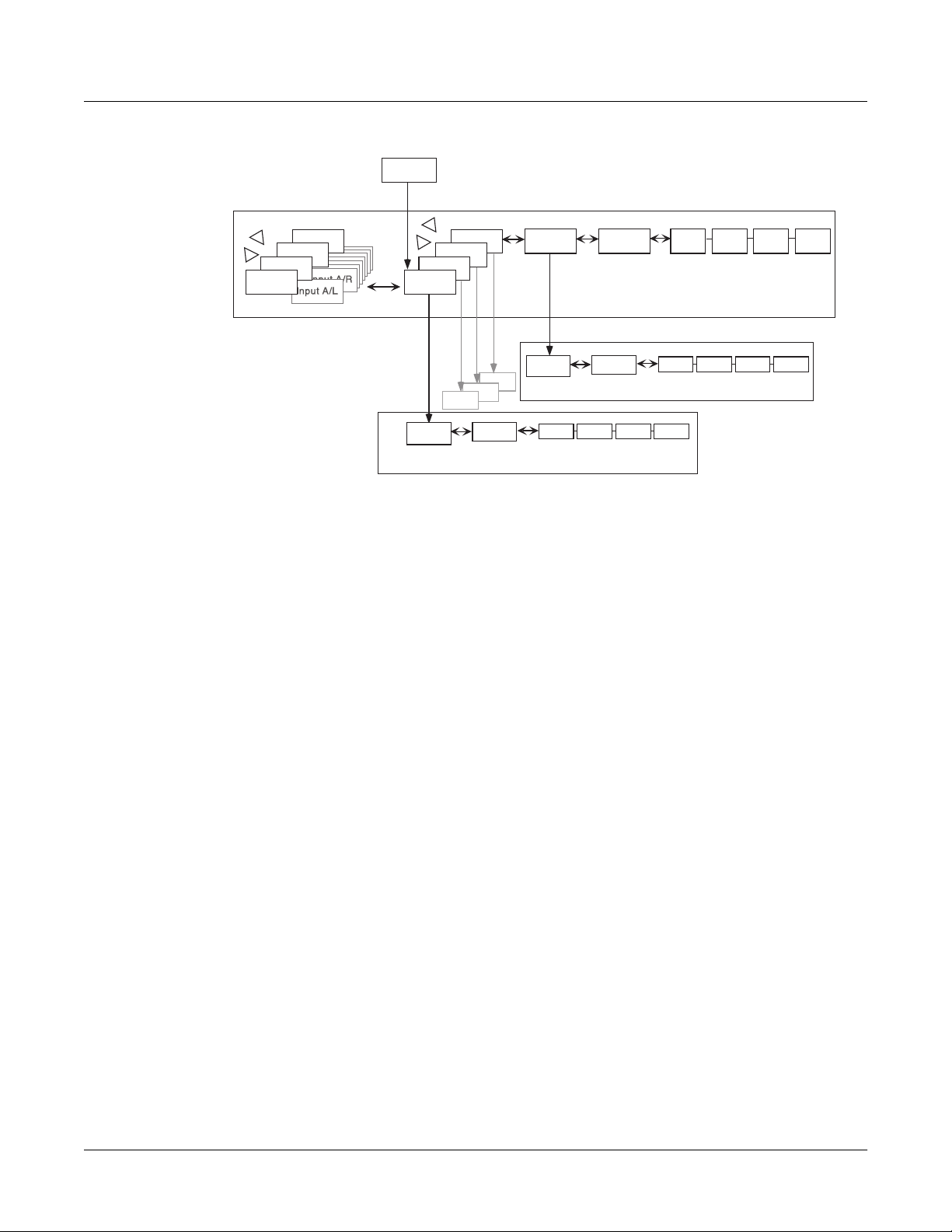
creates a different program (if you save it). The user interface within a studio is organized
according to the following diagram:
15-1
Page 2
Advanced KDFX
Navigating KDFX
Studio|
Edit
Chan/Bank
FXBus 2
FXBus 1
Edit
algorithm
param 1
Insert FX
FXBus 4
FXBus 3
param 2
FX Preset (1-4)
AuxFX
Edit
algorithm
param1
<more>
param 2
Name
Save Delete Dump
<more>
Output
<more>
Save
Name
Name
Save Delete Dump
FX Preset (Aux)
Delete Dump
Studio
Chan/Bank
Input A
Effects Mode
Input D
Input C
Input B
(if mono)
Figure 15-1 The KDFX User Interface
To select a studio, go to the main Effects page if youÕre not already there (from Program mode,
press Effects to go into Effects mode), and move the cursor so the studio name is highlighted.
FXBus
EffectMode|||||Xpose:0ST|||||<>Channel:1|
FX|Mode:Master
FX|Chan:None
Studio|:2|HallFlngCdD|Room||
Effect|:1|Sweet Hall
Wet/Dry:0%Wet
Dither|:Medium||||||DigOut|:16|Bit
Octav-|Octav+|Panic|||||||||Chan-||Chan+
When the studio is highlighted, pressing Edit goes to the Studio Editor (EditStudio) level, and
the FXBUS page. There are four FXBUS pages, one for each FXBus in the studio. These four
buses are the inputs to KDFX, and receive the output from the K2600Õs sound engine, as deÞned
on the OUTPUT page in the Program Editor.
Select the desired FXBUS page using the
Channel / Bank Up and Down buttons. If you have just
entered the Studio Editor, the Þrst FXBUS page you see will be the one for FXbus1. Once you are
15-2
Page 3

Advanced KDFX
Navigating KDFX
inside the Studio Editor, however, when you press the FXBUS soft button from another page, it
will take you to whichever FXBUS page you were last looking at.
EditStudio:FXBUS|Size:1|Free:0|<>FXBus:1
FX1||14|string|lHall|||||||Aux| ||Mix
Wet/Dry|||:32%wet||||Lvl:0ff|||Lvl:0.0dB
Out|Gain||:0.0dB|||||Bal:0%||||Bal:0%
Allocation:Auto
<more||INPUT||FXBUS||AUXFX||OUTPUT|more>
The four FXBuses are the equivalent of four effects processors inserted into the effects loop of a
mixing console. Therefore, they are also known as the Insert effects .
Parameters
When you are on an FXBUS page, highlighting the name of the FX preset (or any of the
parameters directly below it) and pressing Edit accesses the Þrst page of parameters for that
FX preset. An FX preset is an object within the studio, much like a keymap is an object within a
program. The same FX preset can be used in more than one studio, or more than once in the
same studio (provided you donÕt run out of PAUs).
The Þrst EditFXPreset Parameter page includes the algorithm on which the FX preset is based.
The soft buttons take you to additional pages of parameters. Depending on how complex the
algorithm is, there may be as many as four parameter pages in an FX preset. Algorithms are in
the KDFX ROM, and are not normally changeable, deletable, or saveable by the user. Like ROM
samples, they are simply always there. (You can load additional algorithms from disk, however,
as they become available from Kurzweil.)
EditFXPreset:PARAM1||||||||EffectSize:3/3
FXAlgorithm:5|MiniVerb|||||||||||||
||||||||||||||||||||In|Gain|||:0.0dB
Wet/Dry|||:32%wet|||Out|Gain||:0.0dB
Rvrb|Time|:2.6s|||||HF|Damping:8372Hz
L|Pre|Dly|:4ms||||||R|Pre|Dly|:9ms
<more||PARAM1|PARAM2|||||||||||||||more>
Pressing the
for the FX preset.
<more> soft buttons gives you access to the Name, Save, Delete, and Dump pages
Pressing Exit goes back to the FXBUS page, and if you have made any changes in the FX preset
you will be prompted to save it. If the FX preset in this bus is the same as on another bus (either
in this studio or another), then any changes you make (and save) will affect all buses using that
FX preset.
15-3
Page 4
Advanced KDFX
Navigating KDFX
Input
From the FXBUS page, or anywhere inside the Studio Editor, pressing the INPUT soft button
brings you to the Input A page.
EditStudio:INPUT||||||||||||<>Input:||A|
SP
||A||LoShelf||HiShelf||FXBus1||FXBus2
|||G:0.0dB||G:0.0dB||Lvl:0.0dB|Lvl:Off
|||F:123Hz||F:9956Hz|Pan:0%||||Pan:0%
|||||||||||||||||||||Wid:100%||Wid:100%
<more||INPUT||FXBUS||AUXFX||OUTPUT|more>
The other Input pagesÑB, C, and DÑare selected by using the Chan / Bank Up and Down
buttons. Depending on how the inputs are conÞguredÑstereo or monoÑthere will be from four
to eight Input pages.
Similar to the FXBUS pages, the Þrst time you look at an input page after entering the Studio
Editor, it will be the Input A page (or, if itÕs mono, the Input A/L page). Once you are in the
Studio Editor, when you press the INPUT soft button from another page, it will take you to
whichever input page you were
last looking at.
Aux FX
From inside the Studio Editor, a soft button accesses the AUXFX page. This is a separate effects
bus, which can be used by itself, or in a chain following one or more of the FXBuses.
Like the FXBuses, you can view and edit the FX presetÕs parameters, including its algorithm, by
highlighting the FX presetÕs name and pressing Edit . As on the insert FXBuses, the FX preset on
the Aux bus has up to four pages of parameters, and the <more> soft buttons access Name,
Save, Delete, and Dump pages for the FX preset. The same FX preset can be used in the Aux bus
as in any of the insert FXBuses.
EditStudio:AUXFX|Size:3|Free:0||||||||||
||Aux||3|Tabla|Room||||||||||||||Mix
|||Wet/Dry|||:100%wet|||||||||||Lvl:0.0dB
|||Out|Gain||:0.0dB|||||||||||||Bal:0%
<more||INPUT||FXBUS||AUXFX||OUTPUT|more>
15-4
The AUXFX page can also be accessed from any of the FXBUS pages by placing the cursor on the
box labelled Aux and pressing Edit .
Pressing Exit goes back to the AUXFX page on the EditStudio level. If you have made any
changes in the FX preset, you will be prompted to save the FX preset.
Page 5

Advanced KDFX
Navigating KDFX
Output
In the Studio Editor, pressing the OUTPUT soft button accesses the OUTPUT page, where the
KDFXÕs ÒvirtualÓ outputs are assigned to the K2600Õs physical outputs.
EditStudio:OUTPUT|||||||||||||||||||||||
Mix|Lvl:0.0dB||||||Output|A:Mix
Mix|Bal:0%|||||||||Output|B:Off
|||||||||||||||||||Output|C:Off
|||||||||||||||||||Output|D:Off
<more||INPUT||FXBUS|AUXFX||OUTPUT|more>||
The OUTPUT page can also be accessed from any of the FXBUS pages by placing the cursor on
the box labelled Mix and pressing Edit.
Name, Save, Delete, Dump
From any of the EditStudio pages, pressing either of the <more> soft buttons accesses Name,
Save, Delete, and Dump pages for the studio. Studios are stored in RAM, like K2600 programs,
and when a studio is recalled, all of its associated FX presets and parameters are recalled with it.
Studios in ROM occupy slots in the zeros, 100s, 700s, and 800s banks. You may override these if
you like, or use the RAM banks (200-699 and 800-999) for your studios. The ROM studios are
always there, and if you delete a studio that youÕve stored in a ROM slot, the original ROM
studio will pop up in its place.
When you save a studio, you can also rename it, using the standard naming dialog:
EditStudio:Rename|||||||||||||||||||||||
Studio|Name:||||H
Delete|Insert||<<<||||>>>||||OK|||Cancel
allFlngChD|Room
The Compare and FX Bypass Buttons
As with all K2600 objects, the Compare (Disk) button lets you switch back and forth between
the last saved version of whatever you are editing and its current state.
If you are on a page at the EditStudio level, Compare toggles between the last-saved and current
versions of the studio. If you are inside an FX preset, on the EditFXPreset level, Compare toggles
between the last-saved and current versions of the FX preset.
If you have changed any algorithms in an FX preset or studio during the current editing session,
the Compare button will switch back to the old algorithms. This can create some short-term
ÒholesÓ in the audio output when the signal momentarily goes dryÑsee the section on
switching studios in real time on page 15-21.
15-5
Page 6
Advanced KDFX
Exploring the Studio Parameters
The Effects/FX Bypass button, when you are in the Studio Editor, bypasses all of the FX presets
(all of the Insert FX and the Aux FX) in the current studio, so that you can hear the signals
without processing. It does not, however, change the EQs, gains and balances, or signal
routingsÑthose will continue to affect the signal you hear.
Exploring the Studio Parameters
WeÕll explore the parameters within the studio in the order in which they affect the signal path,
starting on the Input page.
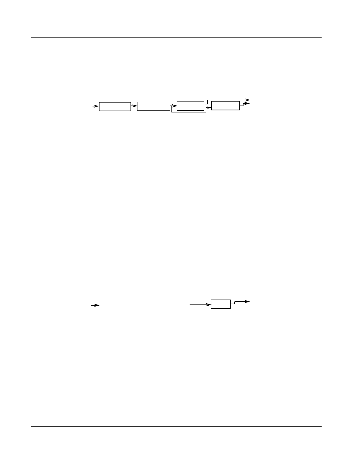
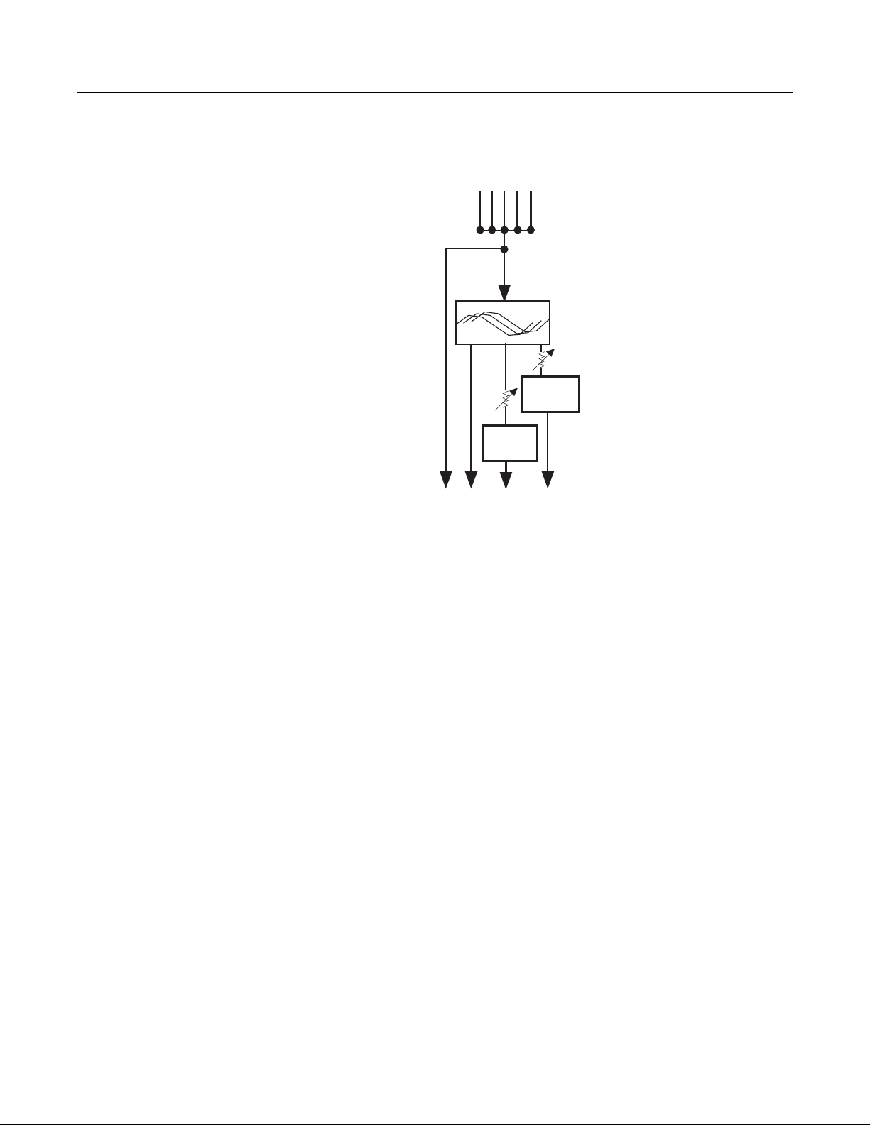
Input Section
K2500 output pair
Mono/Stereo
switch
stereo or L R (if mono)
two-band EQ
Level,
Pan/Balance
Width (if stereo)
To FXBuses 1-4
Figure 15-2 The KDFX Input Editor
Inputs are referred to as A, B, C, and D, and correspond to the four output buses (KDFX-A
through KDFX-D) from the K2600Õs Program Editor. These signals can be treated as stereo pairs
or as individual mono signals. This is determined by the Þrst parameter on an Input page, the
Mono/Stereo switch.
If this switch is set to M, then the left and right channels of the selected program output pair are
split up, and each is given its own Input page, with EQ and FXBus routings. If it is set to SP
(Stereo with Pan) or SB (Stereo with Balance), the two channels of the pair are processed in
parallel.
Selecting the Mono/Stereo mode on one input bus does not affect any of the others, and you can
have any combination of stereo and mono inputs in a studio. Therefore, there can be anywhere
from four to eight Input pages in a studio.
15-6
The Chan/Bank Up and Down buttons let you move among the Input pages.
Page 7

The Arrow Meter
On an Input page, whenever there is signal present on its bus, the arrow next to the letter of the
bus ßashes. This is a good way to check that you have set up your program output routings
correctly. More on this later.
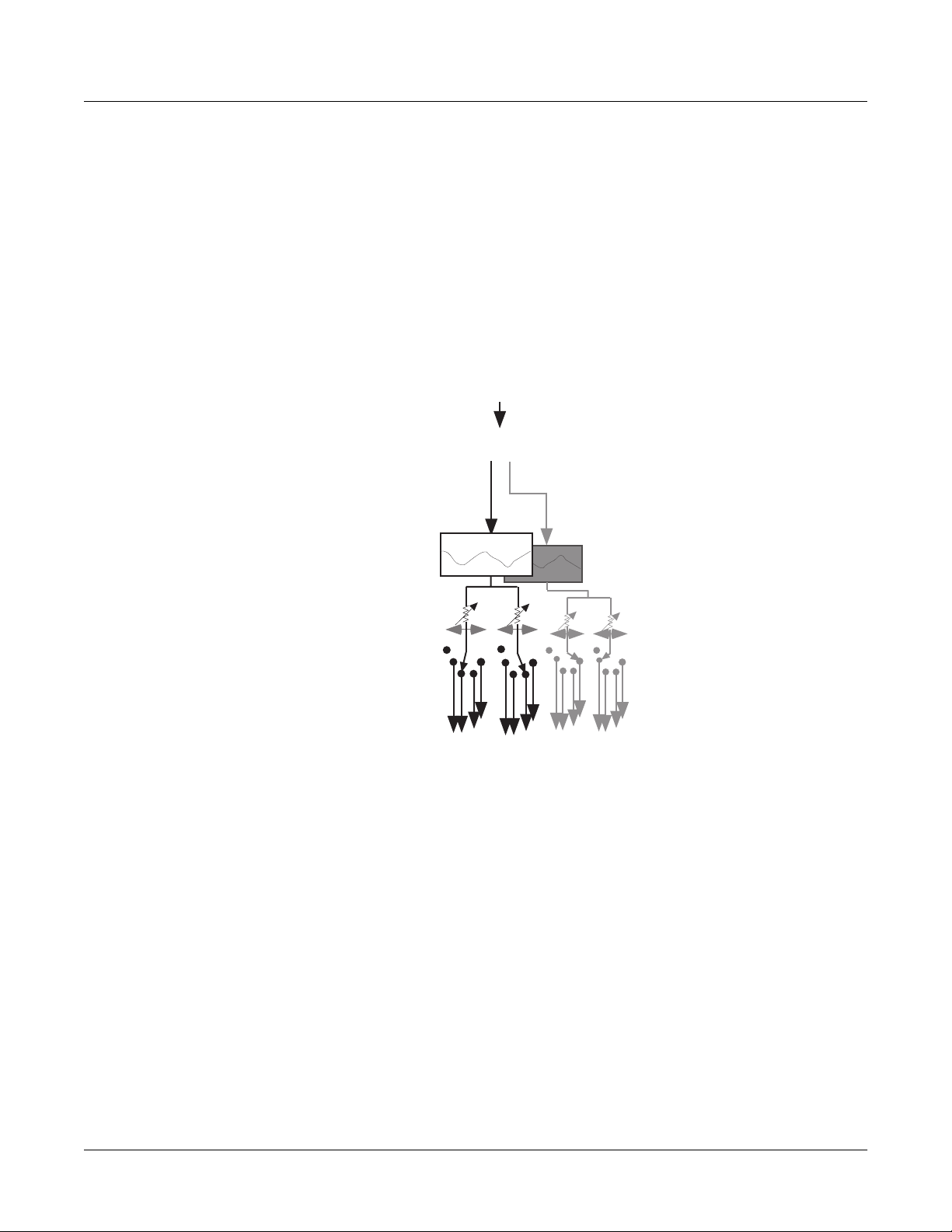
EQ
The input signal Þrst passes through two equalizers. These equalizers are independent of each
other, but the signal is chained: it goes through the left one, then the right one. Each equalizer
has a frequency (F) control and, depending on the mode, a gain (G) control. The mode of each
EQ module is changed by placing the cursor in the appropriate block and turning the Alpha
wheel or using the Plus/Minus buttons. There are eight modes for the Þrst EQ, and six for the
second:
None No effect, the signal passes through unchanged.
LoShelf Boosts or cuts frequencies below the F value by G decibels.
HiShelf Boosts or cuts frequencies above the F value by G decibels.
LoPass1 Cuts frequencies above the F level with a 6 dB/oct (1-pole) slope.
LoPass2 Cuts frequencies above the F level with a 12 dB/oct (2-pole) slope.
Advanced KDFX
Exploring the Studio Parameters
HiPass1 Cuts frequencies below the F level with a 6 dB/oct (1-pole) slope.
HiPass2 Not available on the second EQ. Cuts frequencies below the F level with a steeper 12
ParaMid Not available on the second EQ. Provides a cut or boost centered around the F
FXBus Sends
Following the equalizers are the insert FXBus sends. Each input has two sends. Change the
destination of each send by placing the cursor on it and doing the usual thing with the Alpha
wheel or Plus/Minus buttons.
Either send can be assigned to any of the four FXBuses, or to None, with one exception: the two
sends on a particular input cannot both be assigned to the same FXBus. So, for example, if the
Þrst send on Input B/L is assigned to FXBus2, the second send from Input B/L cannot also be
assigned to FXBus2. You can, however, assign as many different inputs to the same FXBus as you
likeÑincluding the two channels from a mono pair.
Each of the FXBus sends has a level parameter (Lvl) that determines the gain of the signal going
to that send. Maximum level is 24.0 dB, and minimum is -79.0 dBÑthere is also an Off position.
0.0 dB is unity gain.
The FXBus sends are stereo, and if an input is stereo, both channels go to the send.
db/oct (2-pole) slope.
frequency. The bandwidth of the equalizer is two octaves. There is an illustration of
the action of this equalizer mode on page 16-28.
Mono Inputs (M)
If an input is mono, then each of its FXBus sends has a Pan parameter. This determines how the
signal is distributed between the left and right channels going to the FXBus: -100% is left
channel only, 100% is right channel only, and 0% is both channels equally.
15-7
Page 8
Advanced KDFX
Exploring the Studio Parameters
Stereo Inputs with Pan (SP)
If the input is set to SP, then each FXBus send has a Pan parameter and a Width parameter. The
Width parameter determines how much separation there will be between the left and right input
signals as they are sent to the FXBus: assuming Pan is set to 0%, a Width of 100% means the
signals will be completely separate, while 0% means they will be combined into Òdual mono.Ó
Negative numbers ßip the channels around, so that -100% means the channels are separate, but
with left and right reversed, while -50% means they are reversed and partially blended.
The Pan control maintains the stereo image, but ÒtiltsÓ it one direction or the other. At 0% there
is no change to the signal, while at 100% it all goes to the right channel. At 50%, what had been
hard left will now be in the center, and what had been in the center will now be halfway
between center and right. Negative values tilt the signal to the left.
Width (“SP” or “SB”)
Input channels
L
R
Width=100%
L
R
Width=50%
Width=0% Width=-100%
Pan (“SP”) (width=100%)
Pan=100%Pan=0% Pan=50% Pan=-100%
L
R
L
R
Balance (“SB”) (width=100%)
Balance=100%Balance=0% Balance=50% Balance=-100%
L
R
Figure 15-3 Width, Pan, and Balance controls
A Word About Gain
The Pan, Balance, and Width controls all have constant power curves, so that the combined
signal level doesnÕt change when you move the signals from side to side. However, if you use
several Pans or Balances on a signal to keep the channels isolated throughout the entire signal
chain (for example, if the Input send is panned 100%, and so are the Aux send, the Mix send, and
the Mix output), you can increase the gain of the signal considerably.
L
R
15-8
Each stage of hard-panning adds 3 dB, so the increase in gain when the signal reaches the Þnal
output can be as high as 12 dB. In this case, you may want to trim the level at various stages to
keep the signals from getting too hot.
Page 9

Effects Buses
The four insert Effects buses (FXBuses) receive the signals from the Input Editor and process
them. Press the FXBUS soft button to go to one of the FXBUS pagesÑthe Þrst time you do this
after entering the Studio Editor, it will be the FXBus1 page.To go to the other FXBUS pages, use
the Chan/Bank Up and Down buttons. The number of the FXBus appears in the upper right
corner.
The Arrow Meter
There are arrow meters on the FXBUS pages as well, right next to the number of the FXBus.
These tell you when signal is coming into the bus, and also when signal is present inside the bus,
so if you have a long reverb or repeating delay, for example, the arrow will keep ßashing as long
as the processing is going on.
FX Preset
The Þrst parameter on an FXBUS page is the FXBusÕs FX preset. Set the cursor on it, and use the
Alpha wheel to scroll through the FX presets currently in memory. If an FX preset name comes
up in parentheses, for example, (Really Big Plate), it means there is not enough processing
power (PAUs) available at the moment to use this FX preset in this FXBus. WeÕll get to PAUs in a
moment. 199 No Effect is a ÒblankÓ FX preset, in which all signals pass straight through without
any processing. It can be used as a starting point for creating your own FX preset. If you want to
set up a ÒdummyÓ effects bus to pass signal directly to the Aux bus, use 0 None.
Advanced KDFX
Effects Buses
Bus Outputs
The parameters on the right side of this page determine how the effected signal gets to the
KDFX outputs. Each FXBus has four outputs, all of which are stereo:
¥ Its own dry (pre-effect) output
¥ Its own wet (post-effect) output
¥ The Mix bus
¥ The Aux bus
The output to the Mix effects bus has a level control with a range of -79.0 to +24.0 dB, and an Off
position. It also has a Balance control that works similarly to the Balance control on the inputs,
by setting the relative levels of the two output channels. The signal is mixed with similar signals
from the other FXBuses onto the Mix bus, which can be accessed on the OUTPUT page.
The output to the Aux bus has an identical pair of controls. Its signal goes to the global Aux
effects bus, where it is mixed with similar signals from the other FXBuses, and then put through
the Auxiliary Effects processor. From there it can be accessed on the OUTPUT page.
15-9
Page 10
Advanced KDFX
Effects Buses
There is no external level control over the output of the FXBus itselfÑit just shows up, in preeffect and post-effect versions, on the OUTPUT page.
From Input editor
Pre FXBus
FXBus
to Aux
FX bus
to Mix
bus
To Output editor
Figure 15-4 FXBus Signal Routing
The Aux Bus
The Auxiliary effects bus is accessed by pressing the AUXFX soft button on any page in the
Studio Editor. It contains an FX preset, which is separate from those in the insert FXBusesÑ
although it can be the same FX preset that is in use on one or more of the insert FXBuses. There
is no Allocation parameter, because the Aux bus has a Þxed allocation of 3 PAUs. Only a very
few highly complex FX presets require more than 3 PAUs, so as you scroll through the
FX presets here you wonÕt see many names in parentheses.
Aux Bus Outputs
There are two outputs from the Aux bus: itself, and a feed (post-effect) to the Mix bus. The feed
to the Mix bus, where it is combined with other Mix bus feeds from the four FXBuses, has level
and balance controls. The Aux busÕs own output has no post-effect controls, and goes right to
the OUTPUT page.
15-10
Page 11
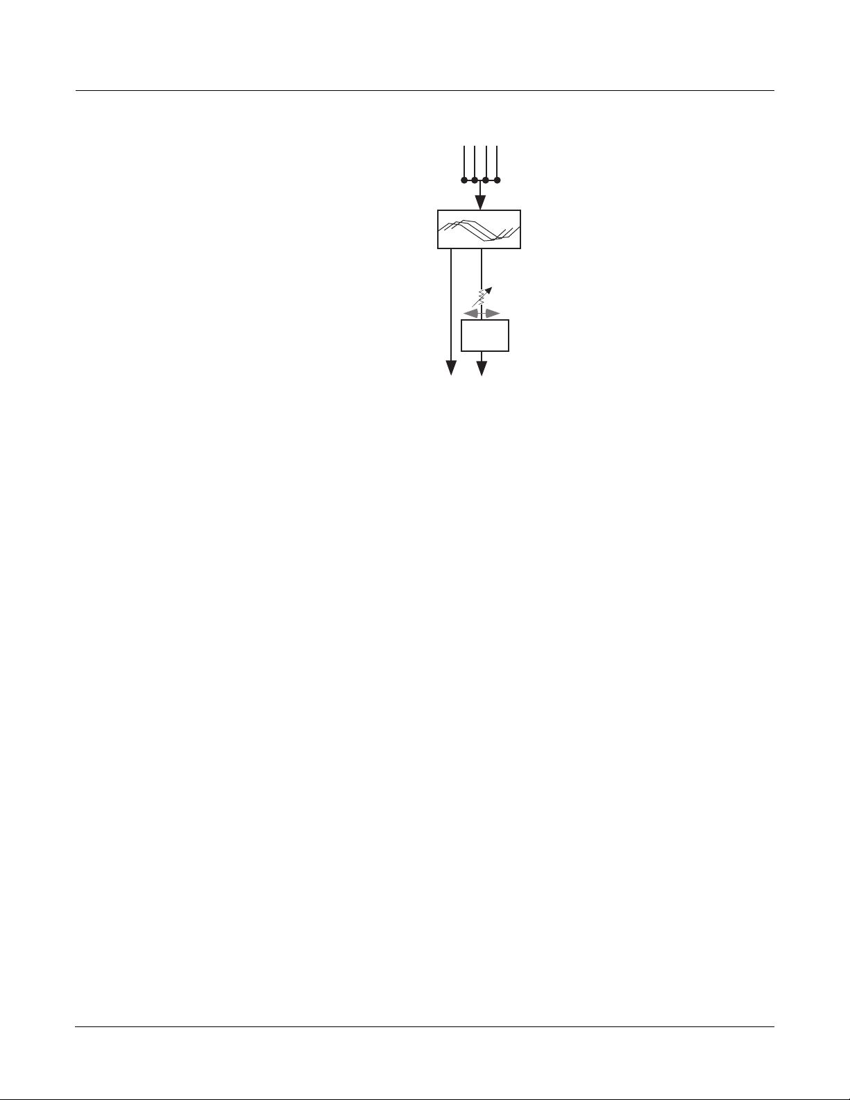
Figure 15-5 Aux Bus Outputs
About FX Presets
FX presets are where the processing takes place in KDFX. Each of the insert FXBuses and the
Aux bus have their own FX preset, and they are all independent of each other. If you think of a
studio as being the equivalent of a K2600 program, then an FX preset is the equivalent of a layer
or keymap.
From Insert
FXBuses’
Aux sends
To Output
editor
Advanced KDFX
Effects Buses
AuxFX
to Mix
bus
In any of the FXBuses, the FX preset is edited by placing the cursor on the name of the FX preset
and pressing Edit.
The Þrst parameter page, or PARAM1, appears. The algorithm that the FX preset is based on is
selected at the top of this page. Highlight the name on the FXAlgorithm line, and scroll through
the various algorithms. The algorithms are in the K2600Õs ROM (like ROM samples), and are not
changeable by the user. As you change algorithms, the parameters displayed on the page change
accordingly.
EditFXPreset:PARAM1||||||||EffectSize:3/3
FXAlgorithm:1|Panaural|Room||||||||||
||||||||||||||||||||In|Gain|||:0.0dB
Wet/Dry|||:30%||||||Out|Gain||:2.0dB
Room|Size|:15.2m
Pre|Dly|||:4ms||||||Decay|Time:1.7s
HF|Damping:14080Hz
<more||PARAM1|PARAM2|||||||||||||||more>
Notice also that as you scroll the algorithms, the EffectSize parameter in the upper-right corner
changes. This parameter shows how many Processing Allocation Units (PAUs) the currently
selected algorithm requires, followed by how many are available for this FX preset. If, for
example, EffectSize is 2/3, that means the algorithm requires 2 PAUs, and there are 3 PAUs
available. More about PAUs soon.
Just below and to the right of the algorithm name is an Input Gain parameter, which adjusts the
level of the signal coming into the FX preset from the input(s) sending to it. The relative level of
the various inputs is determined on the Input pages, but you can change the overall level hereÑ
15-11
Page 12

Advanced KDFX
Effects Buses
Bus Overrides (Bus Mods)
for example, if youÕve combined several inputs into one FXBus and the signal is too hot for the
FX preset, you can pad it down here. The Trim is adjustable from Off/-79.0 dB to +24 dB.
Below the Input Gain is usually (but not always) an Output Gain, which sets the level of the
signal leaving the FX preset, which can be further modiÞed by the Mix and Aux sends on the
FXBUS page.
The other parameters that appear on this page are determined by the algorithm. Each algorithm
has its own set of parameters, which may take up as many as four pages, accessed using the soft
buttons PARAM2, PARAM3, etc. The parameters associated with each algorithm are discussed
in detail beginning on page 15-35, and at the beginning of Chapter 10 of the MusicianÕs Reference.
When you change a parameter on one of these pages, you have changed the FX preset, and if
you want the change to be permanent, you must save the FX preset. Pressing either of the
<more> soft buttons accesses Name, Save, Delete, and Dump pages for the FX preset. FX presets
are stored in RAM, just like K2600 keymaps. When an FX preset is recalled, either by itself (from
within the Studio Editor) or as part of a studio, its associated algorithm and all parameters are
recalled with it.
There is another way to edit an FX presetÕs parameters without altering the FX preset itself, and
that is by using bus overrides.
We havenÕt yet talked about the two parameters that are on the Insert FXBUS and AUXFX pages,
directly underneath the name of the FX preset. These are called Òbus overridesÓ or Òbus mods,Ó
and they allow you to change parameters within an FX preset without actually going into the
FX preset.
Wet/Dry||||:35%
Out|Gain|||:2.0dB
For example, the bus overrides on FX1 are often Wet/Dry mix and Output gain. Normally, these
parameters would be found inside the FX preset, and if you changed them, youÕd have to save
the new FX preset in order to keep the changes.
Instead, using bus overrides, you can adjust these two parameters and hear what they sound
like while you are adjusting them without going into the FX preset. When you save the studio,
these parameter values are saved, but they are not part of the FX presetÑthey are part of the
studio. Therefore, the FX preset remains unchanged (and if the FX preset is in use elsewhere, it
hasnÕt changed there), but these two parameters in this particular FXBus have been altered.
Wet/Dry and Out Gain are the default bus overrides you will encounter most often, but in some
algorithms and FX presets, other parameters are accessed as bus overrides. For example, on
some compressor algorithms, the Þrst bus override is an In/Out switch; and on some dualchannel delay and Þlter algorithms, the overrides are separate Wet/Dry controls for the left and
right channels.
Making and Breaking Bus Overrides
Some studios supplied with KDFX, when you Þrst encounter them, have the bus mods in place,
but they are not engagedÑthat is, theyÕre not actually overriding anything, but instead simply
show the values of the corresponding parameters inside the FX preset unchanged. To see this,
choose an FX preset on the FXBUS page and look at the values of the override parameters, Wet/
Dry and Out Gain. Now go inside the FX preset by highlighting the FX presetÕs name and
15-12
Page 13
Advanced KDFX
Effects Buses
pressing Edit, and Þnd those two parameters on the Þrst parameter page (PARAM1). YouÕll see
their values are the same as on the FXBUS page.
EditStudio:FXBUS|PAU:3|Free:1||<>FXBus:1|
FX1||2||Big|Room|||||||||||Aux ||Mix
Wet/Dry :35%|||||Lvl:0ff |Lvl:0.0dB
Out Gain :0.0dB|||Bal:0%||||Bal:0%
Allocation:Auto
<more||INPUT||FXBUS||AUXFX3|OUTPUT||more>
Edit
Exit
EditMultiFX:PARAM1|||||||||EffectSize:3/3
Algorithm:1|Panaural|Room
||||||||||||||||||||In|Gain|||:0.0dB
Wet/Dry|||:35%||||||Out|Gain||:0.0dB
Room|Size|:16.0m
Pre|Dly|||:4ms||| Decay|Time:2.9s
HF|Damping:15804Hz
<more||PARAM1|PARAM2||||||||||||||||more>
Figure 15-6 Bus Overrides in Place, But Not Engaged
Press Exit to go back to the FXBUS page.
To engage a bus override, you have to use it, which you do by moving the parameter away from
its nominal value on the FXBUS page. Do that, and then go back inside the FX preset.YouÕll see
that the value of the parameter youÕve changed is now shown as BusMod, meaning that the
FX preset parameter is under the control of the bus override.
15-13
Page 14
Advanced KDFX
Effects Buses
EditStudio:FXBUS|PAU:3|Free:1||<>FXBus:1|
FX1||2||Big|Room|||||||||||Aux ||Mix
Wet/Dry :45%|||||Lvl:0ff |Lvl:0.0dB
Out Gain :1.0dB|||Bal:0%||||Bal:0%
Allocation:Auto
<more||INPUT||FXBUS||AUXFX||OUTPUT||more>
Edit
Exit
EditMultiFX:PARAM1|||||||||EffectSize:3/3
Algorithm:1|Panaural|Room
||||||||||||||||||||In|Gain|||:0.0dB
Wet/Dry|||:BusMod|||Out|Gain||:BusMod
Room|Size|:16.0m
Pre|Dly|||:4ms||| Decay|Time:2.9s
HF|Damping:15804Hz
<more||PARAM1|PARAM2||||||||||||||||more>
Figure 15-7 Bus Overrides Engaged
If you now change the parameter value from inside the FX preset, it breaks the bus override. By
doing this, however, you have changed the FX preset, and when you leave the FX preset you
will be asked if you wish to save it. If you then save the FX preset, the bus mod will be
permanently broken, but if you donÕt save the FX preset, it remains in its previous state, which
means the bus mod remains intact.
Since bus overrides are part of the studio, they are not saved permanently until the studio is
saved.
15-14
Changing the Bus Overrides
The default bus overrides that come up when you are working in a studio are often convenient,
but you arenÕt required to use them as they are. You can assign any two of the FX presetÕs
parameters to the bus overrides. (You cannot, however, assign both bus overrides to the same
parameter.) When you save the studio, the parameters youÕve selected for the bus overrides on
each FXBus are saved, along with their values.
If you set up a bus override and adjust a parameterÕs value, and then change your mind and
assign a different parameter to that override, the value of the Þrst parameter (the one no longer
assigned to a bus override) will revert to its original valueÑthat is, the value set inside the
FX preset. This can be a helpful feature, in that it means you can use bus overrides as a
ÒwindowÓ into an FX preset by scrolling through the various parameters. But keep in mind that
you canÕt use this method to tweak parameters, because as soon as you move on, the parameter
you tweaked gets Òuntweaked.Ó
Page 15

Allocation
Understanding PAU allocation and how it works is very important for using KDFX to its fullest
potential.
What’s a PAU?
The basic unit of signal processing in KDFX is the Processing Allocation Unit, or PAU. There are
a total of 4 PAUs that can be split among the four insert FXBuses, and another 3 PAUs for the
Aux bus. These two sets of PAUs are distinct and are not interchangeable.
The number of PAUs on an FXBus is determined by the algorithm inside its FX preset. Different
algorithms require different numbers of PAUs, as shown in the Size parameter at the top of the
screen when you are on the FXBus edit page:
EditStudio:FXBUS|Size:2
or inside an FX preset:
EditFXPreset:PARAM1|||EffectSize:2/1
Advanced KDFX
Effects Buses
A simple delay, ßanger, compressor, exciter, or small reverb uses only 1 PAU. A complex phaser,
pitcher, or multiband tone control uses 2 PAUs. A really complicated reverb or graphic equalizer
may use 3 PAUs. Only a handful of really wild algorithms use 4 PAUs.
The Allocation parameter on each FXBUS page determines how many PAUs are available for the
FX preset assigned to that bus. If the parameter is set to 1, then only FX presets that use
algorithms requiring 1 PAU will be available for the bus. If you try to assign an FX preset that
requires more PAUs, its name will show up in parentheses, and the sound will pass through the
bus unprocessed.
If you know you want a certain FX preset in a particular FXBus, you can select it, and then set
the Allocation parameter for that bus to match the PAU requirements of the FX preset.
A PAU is a Terrible Thing to Waste
Be careful not to set the Allocation parameter too high. If you set it on some bus to 3, for
example, and you are using an FX preset on that bus that requires only 1 PAU, the other 2 PAUs
are being wasted, since they are not available to be assigned to other buses. The other busesÕ
Allocation parameters will not go higher than 1, and therefore no FX presets whose Size is
greater than 1 can be selected for any of them.
PAUs are normally allocated on a Þrst-come, Þrst-served basis. If you set one FXBus to a PAU of
3, then you will be able to set the Allocation on the next bus you set to 0 or 1 only. If you then set
that second bus to 1, then you wonÕt be able to set a value greater than 0 for any of the other
buses.
If you know that you wonÕt be using an FXBus, or that youÕll be using it only as a ÒdummyÓ to
route signals somewhere else, you can set its Allocation to 0.
Auto Allocation
On any of the buses, you can set Allocation to Auto. Auto means that the PAU allocation for that
bus will automatically adjust itself to the currently selected FX preset. However, Auto obviously
cannot create PAUs when they are in use elsewhere, and Allocations that have been manually
15-15
Page 16

Advanced KDFX
Effects Buses
set take precedence over Auto Allocations. So for example, if you set the Allocation of FXBus1
to 3, and set the Allocation of FXBus2 to Auto, the maximum number of PAUs available to
FXBus 2 is still only 1, and if you try to load a Size-2 FX preset into FXBus2, it wonÕt work and
the FX presetÕs name will show up in parentheses.
If all busesÕ Allocations are set to Auto, then PAUs are not allocated Þrst-come, Þrst-served, but
instead are allocated in numerical bus order: if an FX preset requiring 3 PAUs is loaded into
FXBus1, then only 1 PAU will be available for the other buses, regardless of which FX preset got
assigned to which bus Þrst.
A parameter called Free appears at the top of every FXBUS page, telling you how many PAUs in
the current studio are unallocated and available.
Effect Size
While youÕre editing an FX preset and selecting algorithms for it, the EffectSize parameter at the
upper right of the EditFXPreset page informs you of the PAU situation. The Þrst digit in this
parameterÕs value is the number of PAUs the currently selected algorithm requires, and the
second digit is the number that have been allocated to the bus, either manually or automatically.
If the Þrst digit is larger than the second, the algorithm is not available, and if you choose it, its
name will show up in parentheses and the sound will pass through unprocessedÑjust like an
unavailable FX preset on an FXBUS page.
If the FXBusÕs Allocation is Auto, when you change the algorithm inside the FXPreset Editor,
both digits of the EffectSize display will change. If you call up an algorithm that requires more
PAUs than are currently available, the second digit will change to 0Ñsince the algorithm canÕt
be loaded, the PAUs are freed up for use elsewhere.
Designing with PAUs
One simple way to use Allocations when designing a KDFX studio is to put all of the buses in
Auto, and start with your most complex processing on FXBus 1, then assign other FX presets to
the other buses as they are available.
PAUs on the Aux Bus
The Aux bus is a whole separate processor with 3 of its own PAUs. Allocation is not an issue
with the Aux bus, since its 3 PAUs are assigned to it permanently. (There is a fourth PAU in the
Aux bus, but it is used for mixing and routing, and so itÕs not available.)
Any FX preset with a PAU requirement of 1, 2, or 3 can be used. When editing the Aux bus,
thereÕs no need for an Allocation parameter or a Free parameter. However, when you are
scrolling through algorithms, the EffectSize parameter will be displayed, with its second digit
always 3. Should you try to access an algorithm on the Aux bus that requires 4 PAUs, the name
of that algorithm will be displayed in parentheses.
The Aux bus is generally used as a global processor, but it doesnÕt have to be. You can set up one
FXBus as a ÒdummyÓÑset its FX preset parameter to 0 NoneÑand send its output to the
Aux bus, and at the same time turn off the Aux sends from all the other buses. Now the Aux bus
can function as an insert FXBus, with 3 PAUs all its own. So if you run into trouble with PAUs on
the insert FXBuses and can sacriÞce a global effect, this is one solution.
15-16
Page 17

Metering
All Input and FXBUS pages have rudimentary signal meters (the arrows), as weÕve seen. On the
Input pages, the arrow next to the input letter ßashes when there is signal present at the input.
On the FXBUS and AUXFX pages, the arrow next to the FXBus number ßashes as long as there is
signal being processedÑin effect, itÕs an output meter. The arrows ßash whenever the signal
level exceeds 14 bits below full scale, which is -84 dB relative to the maximum level the KDFX
can handle. Since typically the K2600 operates with about 20 dB of headroom, this translates to
about -64 dB relative to normal operating level
EditStudio:AUXFX|
||Aux||103|||||||
In addition, a number of KDFXÕs algorithms include a fast visual metering system for
monitoring what the algorithms are doing. Many of these algorithms deal with dynamics
control like compression and limiting. An example is Algorithm 950 HardKneeCompress.
Meters are most often found on the PARAM2 page of the FXPreset Editor:
Advanced KDFX
Effects Buses
EditFxPreset:PARAM2|||HardKneeCompress||
Atk|Time||:0.0ms||||Ratio|||||:3.0.1||||
Rel|Time||:5100ms|||Threshold|:-28.0dB||
SmoothTime:1.4ms||||MakeUpGain:0.0dB||||
Signal|Dly:0.0ms||||||||||||||||||||||||
|||||||||||||||||||||||||||||Reduction||
|||||||-dB|40||20|12|8|6|4|2|0||||||||||
<more||PARAM1|PARAM2|||||||||||||||more>
In this algorithm, the meter is showing the gain reduction that the compressor imposes on the
signal coming into it.
Metering is also used for other purposes in some other algorithms, for example 902 LFO Sweep
Filter. In this algorithm, the meters show the current center frequency of the left and right Þlters
as they sweep up and down the spectrum:
EditFXPreset:PARAM2||||LFO|Sweep|Filter
FilterType:Lowpass||Min|Freq||:58Hz
Resonance|:20dB|||||Max|Freq||:8372Hz
L|Phase|||:0.0deg|||R|Phase|||:0.0deg
L|||||||||||||||
0Hz||2k|||4k|||6k|||0Hz||2k|||4k|||6k|||
<more||PARAM1|PARAM2|||||||||||||||more>
|||
R|||||||||||||||
|
Meters use up a certain amount of KDFXÕs processing power, although less than a whole PAU,
and so they are only used in algorithms where extra power is available. If an algorithm would
need to increase its SizeÑsay, from 2 PAUs to 3Ñwith the addition of metering, then metering
has not been included in that algorithm. This is to ensure that the maximum amount of
processing power is available for actual signal processing.
15-17
Page 18

Advanced KDFX
Output Section
Output Section
Insert
FXBuses
Pre FXBus2
FXBus2
Pre FXBus3
FXBus3
Pre FXBus4
FXBus4
∑
Aux
effect
Mixer
FXBus1
Pre FXBus1
Off
Aux
Mix
Physical outputs
A
Physical
Output A
Output B
Figure 15-8 FXBuses and Physical Outputs
In the Output section, the various signal paths are routed to the K2600Õs physical outputs. Each
of the four output pairs, A, B, C, and D, has a selector switch to determine which signal it will
carry. All signals are stereo. The choices are:
Off No output.
PreFXn The signal coming into the FX preset on FXBus1, 2, 3, or 4. All of the EQs and
pan/width/balance settings of the input modules that are assigned to FXBusn are
active on this signal path, but the FX preset is not.
FXBusn The direct output, post-FX preset, from any of the four insert FXBuses.
Mix The signal from the Mix output, which can include the sum of any or all of the insert
FXBuses, and/or the Aux bus. The Level and Balance parameters on this page control
this output.
Output C
Output D
15-18
AuxFX The outputs of the Aux bus.
There are no restrictions on the settings. If you like, all four outputs can be carrying the same
signal: PreFX1, for example.
Page 19

Separate Analog and KDS Outputs
The K2600Õs separate analog outputs (four pairs, AÐD) are wired in parallel and are ÒliveÓ at all
times. So are the eight digital outputs (also four stereo pairs) available with the digital I/O
(KDS) upgrade option. The parameters on the OUTPUT page affect both the separate analog
and KDS outputs.
Analog Mix Output
The K2600Õs analog Mix output combines the four output pairs into a single stereo analog pair.
Each of the analog outputs, AÐD, carries the signal from the KDFX bus speciÞed for each output
pair on the OUTPUT page of the Studio Editor. The signal at the Mix output always carries the
summed signal of outputs AÐD; connecting cables to Outputs AÐD does not remove the
corresponding portion of the signal from the Mix outputs.
Advanced KDFX
Output Section
KDFX Bus Output
Mix
(Analog) (Analog,
Figure 15-9 K2600 Analog, Digital, and KDS Outputs
Digital Output
For digital output, youÕll need either the sampling option or the digital I/O (KDS) option. In
either case, the digital output of the K2600 (a single stereo pair) is wired in parallel with output
pair A. It gets whatever signal is routed to Output A on the OUTPUT page of the Studio Editor.
With the digital I/O option, you can use the XLR or optical outputs, or the separate KDS outputs
(although this requires the Kurzweil DMTi digital interface for full functionality). With the
sampling option, you can use the XLR or optical outputs.
The sampling option also enables you to sample the K2600Õs own output.
1. On the Sample-mode page, set the Input parameter to Analog, and the Src parameter to
Int. This routes the signal at the K2600Õs Mix outputs to the analog sampling input,
ignoring the external sampling inputs on the rear panel.
A DCB K2600 Physical Outputs
Digital, or
KDS)
(Analog
or KDS)
(Analog
or KDS)
(Analog
or KDS)
15-19
Page 20

Advanced KDFX
Saving Studios and Other objects
2. Set the Input parameter to Digital, then set the Out parameter, if available, to A/D. This
causes the digital outputs to mirror the signal coming from the K2600Õs Mix outputs. (Set
the Out parameter to Dir to mirror the Output A signal at the digital outs.)
Note: If you donÕt have the Digital I/O option, you wonÕt see the Out parameter, which means that
the digital output mirrors the K2600Õs Mix outputs.
When the Input parameter is set to Analog and the Src parameter is set to Ext, the signal that
appears at the digital output is the signal coming into the K2600Õs external analog inputs, and the
K2600 is acting as a very fancy, very high-quality A/D converter.
Value of Out Parameter Value of Src Parameter Signal at Digital Output
Dir N / A KDFX Output A
A / D Int K2600 Mix Output
A / D Ext K2600 Analog Input
Table 15-1 Digital Output Switch Settings
Saving Studios and Other objects
Saving
Saving a studio or an FX preset is handled the same as any other K2600 objectÑsee Saving and
Naming on page 5-3 if you need help with this.
To save an object, from any of the editing pages within the object, press <more or more>, until
you see the Þle-management pages:
<more||Name|||Save|||Delete|Dump|||more>
Name lets you rename the object, using the standard K2600 naming window. Save lets you save
the object to its present slot or to a different one, and also gives you the option of renaming it
before saving it, or accessing the Object utilitiesÑsee Chapter 13.
Delete deletes the object from RAM. If it is in a slot where there is a ROM studio or FX preset,
then the slot will revert to the ROM studio or FX preset.
Dump performs a MIDI System Exclusive dump of the object over the MIDI Out cable for
external storage.
The Save option is automatically invoked if you have done any editing within an object and you
press Exit.
15-20
Do I Always Have to Make a New Studio?
While it may sound as if every time you make a change in a studio parameter, you have to create
a new studio to save it, this is not necessarily true. Studios do take up room in program RAM,
and although the number of studios that can be maintained inside the K2600 is large, it is not
unlimited. Besides, it can be very cumbersome keeping track of a large number of studios which
have only small differences between them.
Page 21

A way to avoid this problem is to use Program or Setup mode, and use FXModsÑstudioparameter controls that live inside a program or setupÑto make changes in the studio
parameters. When you load the program or setup, the studio changes accordingly. This means
you donÕt have to save each variation in the studio as a separate studio; the variations live in the
program or setup.
See Real-time Control of KDFX below for more information.
Disk Functions
Studios and FX presets are loaded from and saved to disk exactly the same as other K2600
objects. FX presets are dependent objects within studios, so when you save a studio, you are
given the opportunity to save the dependent FX presets as well. (Algorithms are in ROM, so
they donÕt need to be saved.) Again, see Chapter 13 if you need help.
Real-time Control of KDFX
Studios can be static, but they donÕt have to be. One of the most powerful features of KDFX is
the ability to change any of the operating parameters in a studio in real time. Mix levels and
pans, EQ values, effects parameters, and almost any other settings can be controlled
dynamically and smoothly, giving KDFX a high degree of ßexibility in performance and
automation.
Advanced KDFX
Real-time Control of KDFX
KDFX parameters can be controlled from the following
¥ The K2600Õs sliders, wheels, ribbons, and pedals
¥ External MIDI sources like another controller or a sequencer
¥ Internal functions like LFOs, envelopes, and FUN generators
Real-time control of a studio is called effects modulation, and a link between a program or setup
and a studio parameter is called an FXMod.
Linking to Programs and Setups
If youÕre familiar with real-time control of the K2500Õs original internal effects, youÕll be happy
to know that real-time control of studios works the same way.
Real-time KDFX studio control normally originates within a program or setup. For the link
between a studio and a program to work, the FX Mode parameter on the Effects-mode page
must be set to Program. If you want to link a studio and a setup, the FX Mode parameter on the
Effects-mode page must be set to Setup. Setting the FX Mode parameter on the Effects-mode
page to Auto means that it will follow whatever mode the K2600 is inÑProgram or SetupÑ
which can be particularly useful when you are switching between programs and setups in a
Quick Access bank, or when you just donÕt want to worry about which mode youÕre in.
15-21
Page 22

Advanced KDFX
Real-time Control of KDFX
EffectMode||||Xpose:0ST|||||<>Channel:1|
FX|Mode:Program
FX|Chan:1
Dither|:Medium||||||DigOut|:16 Bit
Octav-|Octav+|Panic||||||||Chan-||Chan+
Notice that when FX Mode is set to Program or Setup, the studio is not shown, as it is when the
FX Mode is set to Master. So you canÕt go into a studio and edit it from this pageÑyou have to
go through the program or setup, from its KDFX page.
Note: When FX Mode is set to Auto, then FX Mode follows the K2600Õs operating modeÑitÕs
either Program or Setup. When you are on this page, however, FX Mode is actually Master. But
donÕt screw up your brain thinking about thisÑweÕll get back to it later in this chapter (KDFX in
Auto Mode on page 15-34).
For the sake of clarity, during most of this chapter we will talk about linking KDFX only with programs.
The procedures for linking KDFX to a setup are essentially identical, except for the setting of the
FX Mode.
The KDFX Pages
If you look inside any program, you will see several pages that handle the studio and KDFX
control assignments. Open up a program with the Edit button and press more> until you see
this at the bottom of the display:
<more||KDFX|||FXMOD2|FXMOD3|FXMOD4|more>
These are the FXMod setup pages, and in fact there are eight of themÑpress more> again to see
the others.
<more||FXLFO||FXASR||FXFUN||ImpFX||more>
Go back to the Þrst set (press <more), and press the KDFX soft button to look at the Þrst of the
FXMod setup pages:
EditProg:KDFX|||||||||||||||||All|Layers|
Studio:278|Hall+flange+rm||
15-22
Bus:|Param:|||||Adjust:||Source:||Depth:
FX1||Wet/Dry||||12%wet|||MWheel|||40%wet
FX2||Fdbk|Level|25%||||||MIDI23|||60%
InA||EQ1|Bass|G|0.0dB||||MIDI24|||21dB
<more||KDFX|||FXMOD2|FXMOD3|FXMOD4|more>
Page 23

Advanced KDFX
Real-time Control of KDFX
The top line tells us weÕre in the KDFX section of the Program Editor. The second line shows the
studio that is linked to this program. Any changes made on this page do not directly affect the
studio, they affect only this programÕs control over the studio.
The last three lines (ignoring the Soft buttons) show us which FXMods are active in this
program: one is controlling Wet/Dry mix on insert FXBus1, one is controlling feedback level on
insert FXBus2, and one is controlling the Bass Gain on the Þrst EQ of Input A.
Looking Into the Studio
You can go into this studio, to see what the parameters are doingÑa good idea when you are
setting up FXMods so you understand them in contextÑor to alter a Þxed parameter. You can
do this without leaving the Program Editor: highlight any parameter on this page and press
Edit. When you are done with the studio, pressing Exit will bring you back to this page. If you
have made any changes in the studio, you will be prompted to save the studio, and if you donÕt
do so, the changes will be disregarded.
If you do save the studio, either in the same numbered location or a new one, the new studio
will now be linked to this program. If you have changed the studioÕs number, then youÕll also
have to save the program when you leave the Program Editor, so that the program knows which
studio to link to the next time you call it up.
Setting Up FXMods
The KDFX page allows three different FXMod control assignments to be made. More FXMod
assignments are available on the FXMOD2, FXMOD3, and FXMOD4 pages, each of which has
Þve setups. This gives a grand total of 18 studio parameters that can be under real-time control.
DonÕt worry, you donÕt have to use them all.
Bus Assignments
The Þrst column lets you choose which bus inside the studio you want this FXMod to control:
Input A, B, C, or D (if any of the Inputs is set to Mono, you will get to choose individual
channels, for example A/L and A/R); FXBus 1, 2, 3, or 4; the Aux bus; or the Mix bus.
Parameter Assignments
The second column chooses the speciÞc parameter on the selected bus. Scrolling through the
choices shows that this selection is context-sensitive: it shows only parameters that are being
used in the current studio on the selected bus, so you canÕt make assignments to irrelevant or
nonexistent parameters. It ÒknowsÓ which EQs are active, and what modes they are set to;
which Input sends are assigned and whether the sends are in Pan or Balance mode; what
parameters are being used in the FX preset on the particular bus; etc. If you need to know more
about how the studio is set up, you can go into it and look around, as explained above.
HereÕs an example: set the FX Studio to 201*RngMd/PFD/Plt which we looked at on page 9-16.
Set the bus on the Þrst line to InA. Set the cursor under Param: and scroll the choices. They
correspond exactly to the parameters available in the Input Editor page: level and frequency for
the two EQs, and SendLvl, Pan, and Width for the two FX sends. Note that you cannot change
the FXBus assignments on an input from here; you must do that within the studio itself.
Change the bus to FX1, and all of the parameters from the FX preset on FXBus1 are available for
selection, including Mod Mode and the various settings for the presetÕs internal oscillators, as
well as the busÕs output controls: Mix Level, Mix Balance, Aux Level, and Aux Balance. Change
the bus to AuxFX, and the Aux busÕs parameters are available: levels, delays, room types, etc.
Setting the bus to Mix makes available the Level and Balance controls from that page.
15-23
Page 24

Advanced KDFX
Real-time Control of KDFX
What Can’t Be Controlled
You cannot change any parameters through KDFX that would involve a major reconÞguration
of the studio:
¥ Bus assignments on the Input pages
¥ Selecting FX presets on the FXBus pages
¥ Allocation on the FXBus pages
¥ Selecting algorithms within the FX presets
¥ Bus assignments on the Output page
If you want to be able to change any of these in real time, you will have to create a new studio,
link it to a different program or setup, and then call it up using a Program Change command.
In addition, there are a few parameters that can cause serious glitching if they are changed in
real time. The most common of these are the ÒRoom TypeÓ settings in reverb algorithms. While
there is nothing in the software to prevent you from assigning an FXMod to Room Type, you
need to be aware of the potential consequences. See Static FXMods on page 15-27.
Adjust
The Adjust setting is the starting value of the selected parameter when it is under KDFX control,
similar to the entry value of a controller in a setup. This might very well be different from the
value of the parameter when the studio is not under FXMod control, so donÕt get confused. If
you are in Program mode, and this is the current program, the Adjust value takes precedence
over the studioÕs Þxed value, and itÕs the Adjust value that will be called up when you call up
the program.
Source
The Source parameter determines which real-time controlÑinternal, MIDI, etc.Ñis going to
affect the selected studio parameter. As with all K2600 real-time controls, the range of control
sources is very large:
¥ OFF (the parameter is not affected by any source and stays at its Adjust value)
¥ ON (the parameter is set to the maximum value determined by adding the Adjust and
Depth values)
¥ MIDI Continuous Controllers 1-95 (see Note)
¥ Channel State
¥ Pressure
¥ Pitch Wheel
¥ The usual list of controllers, as described in Chapter 4 of the MusicianÕs Reference: ASRs,
FUNctions, Clocks, LFOs, Internal Controls, Random Generators, etc.
Note: Under some circumstances, particularly when the K2600 is in Setup mode, there are certain
restrictions on which MIDI sources you can use.
15-24
Page 25

Advanced KDFX
Real-time Control of KDFX
Dedicated FXMod Control Sources
There are a few control sources that apply exclusively to FXMods:
¥ FXLFO1, FXLFO1ph, FXLFO2, and FXLFO2phÑtwo LFOs and their phases.
¥ FXASR1 and FXASR2Ñ two three-stage (Attack/Sustain/Release) envelopes with
selectable triggers and Normal, Hold, and Repeat modes.
¥ FXFUN1, FXFUN2, FXFUN3, and FXFUN4ÑFunctions. Yes, more Fun with KDFX!
The ASRs, FUNs, and LFOs work exactly the same way they do in any other part of a program,
except these are extra control sources for use only with FXMods, and are not available for other
program functions. They are global for all of KDFXÑyou canÕt apply these controls to just one
FXBus.
The parameter values for these controls are saved with the program. As we saw earlier, you get
to the pages for the FXMod control sources by pressing the more> soft button until you see these
soft buttons:
<more| FXLFO| FXASR| FXFUN| ImpFX| more>
In the Program Editor, you can also get to these pages directly from the KDFX page or one of the
FXMOD pages: select one of those parameters as a source, and then press Edit.
Tempo-based Parameters
There are several different ways KDFX can respond to tempo information, from the internal
sequencer or an external one. These are discussed later in this chapter (see Tempo-based Control of
KDFX on page 15-32).
Depth
The Depth parameter lets you specify a range of change in values that the real-time control will
make, using the Adjust value as a minimum or starting point. This range can be positive or
negative, and the values are displayed in the context of the studio parameter: seconds, dB, %,
Hz, cents, etc.
At the maximum setting of the Source (for example, Mod Wheel all the way up), the value of the
parameter = Adjust + Depth. So if the parameter is Out Gain, the Adjust is 1.0 dB, the Source is
Mod Wheel, and the Depth is 4.0 dB, then at the Mod WheelÕs highest point, the output gain will
be 5.0 dB.
For Source values less than maximum, the formula is: parameter = Adjust + (Depth x Source),
where the Source is considered to be varying between 0 and 1 (or in some cases, such as Pitch
Wheel, between -1 and +1). So using the same example, when the Mod Wheel is halfway up
(MIDI value 64), the gain is 1.0 + (4.0 x 1/2) = 3.0 dB, and when it is all the way down (MIDI
value 0), the gain is 1.0 + (4.0 x 0) = 1.0 dB.
The formula works the same way for negative Depth values. Given the same example, but with
a Depth of -4.0dB, at the Mod WheelÕs minimum point, the gain will be 1.0 dB; at its halfway
point it will be -1.0 dB (1.0 + (-4.0 x 1/2)); and at its maximum point it will be -3.0dB.
Showing Who’s in Control
When you are in Program or Setup mode and you look inside the current studio or its
FX presets, any parameters that are under FXMod control will not display numerical values, but
15-25
Page 26

Advanced KDFX
Real-time Control of KDFX
instead will say FXMod. DonÕt touch any of those parameters for nowÑweÕll explain why in a
moment.
EditFXPreset:PARAM1|||||EffectSize:3/3
Algorithm:1|Panaural|Room|||||||||||
||||||||||||||||||||In|Gain|||:0.0dB
Wet/Dry|||:FXMod||||Out|Gain||:2.0dB
Room|Size|:FXMod
Pre|Dly|||:4ms||||||Decay|Time:1.7s
HF|Damping:14080Hz
<more||PARAM1|PARAM2|||||||||||||more>
Note that if you look at the studio when FX Mode is in Master, the FXMods will not be displayed,
because the FXMods are not in effect! So donÕt get confused.
Breaking the Links
When FX Mode is Program (or Setup) and you are in the Studio Editor, if you change a
parameter that has been assigned an FXMod, it breaks the linkÑthe parameter is no longer
under FXMod control, but is now a static value. If you now save the studio (either in the same
location or a different one), the link stays broken. However, if you leave the studio without
saving it, and go back to the FXMod pages of the Program Editor, the link automatically
reestablishes itself.
If you change the FX preset on an FXBus, the FXMod links to the preset on that bus may or may
not break. If the preset youÕre calling up uses the same algorithm as the preset youÕre leaving, the
links will stay intact. If it uses a different algorithmÑeven a similar oneÑthe links will break.
On the other hand, if you are inside a preset, and you change its algorithm, that breaks the links.
Again, the links will be reestablished if you leave the preset without saving it.
Links to the Aux and Mix parameters on an FXBus do not get interrupted when you change the
FXpreset on that bus.
The same rule applies when you are on the KDFX page in a program or setup and you change
the studio. Links to the Input and Output pages and the Level parameters on the FXBus pages
will be retained, but links to processing parameters will be retained on a given FXBus only if the
algorithm inside the preset on that bus isnÕt changed.
What About Bus Overrides?
Bus overrides are transparent, as far as KDFX is concerned. Any FXMods that involve a
parameter inside an FX preset are set up directly between the program and the FX preset itself. If
the parameter happens also to be assigned a bus override, it doesnÕt make a difference to
KDFXÑthe program will control the parameter as if the bus override wasnÕt there.
However, bus overrides are still active within a studio, and changing a bus override value in a
studio will, as usual, change its associated FX preset parameter. If there happens to be an
FXMod also controlling that parameter, the FXMod link will be broken, just as if you reset the
parameter from inside the FX preset.
Using FXMods So You Don’t Have to Change Studios
WeÕve mentioned that FXMods are a good way to get around the need to create a new studio
every time you want to make a small change in a studioÕs parameters. The same studio can be
15-26
Page 27

Advanced KDFX
Real-time Control of KDFX
used for many different purposes if you use FXMods to control it. FXMods can set the gain of
the signals going to the various FXBuses, set panning and output levels of the signals from the
buses, conÞgure the mix going to the Aux bus, and even turn FXBuses on or off, as well as set
processing parameters.
Since any parameter except the ones that reconÞgure a studio (see What CanÕt Be
Controlled on page 15-24) can be under FXMod control, the amount of variation between the
various program- or setup-controlled versions of a single studio can be very great.
Static FXMods
Static FXMods, that is, FXMods that are just going to be used to Òset and forgetÓ studio
parameters when a program or studio is called up (as opposed to dynamically controlling
them), are easy to set up. On the FXMOD page, select the bus and parameter you want to
control, set the Adjust value to the parameter value you want, and set Source to OFF. When you
are done, save the program or setup normally. Now whenever you select the program or setup,
the parameters in the FXMods will be immediately reset to the values youÕve speciÞed.
Room Type and other potentially glitch-producing parameters work much better as static
FXMods than they do under dynamic control. If you need to change a Room Type in a reverb
when you change a program, you can do so with a static FXMod without hearing horrible
glitches, as long as you make sure there is no signal passing through the reverb at the moment of
the program change.
Importing Studios From Another Program or Setup
If you have a killer studio with FXMods set up in one program (or setup) and you want to use
the same studio and FXMods in a different program, you donÕt have to rebuild the studio by
hand: you can copy studios between programs or setups in one operation.
Press the ImpFX soft button, and youÕll see this:
Edit Program:Import KDFX
From|Program||200*My|Orchestral|Studio||
(Studio 41|auxChorTube|Plt|||)|
Prog||Setup||||||||||||||||||Import|Cancel
Use the soft buttons at the left to select either a program or a setup as the source for the studio
and FXMods you are importing. Select the number of the program or setup you want to import
from. As you change the program or setup, the studio associated with each program or setup
will display in parentheses below the program or setup.
The studio will also kick in, so you can hear it affecting the program youÕre listening to.
When youÕve chosen a program or setup to import a studio from, press the Import soft button.
ÒKDFX fromÉimportedÓ will ßash on the screen, and you will be returned to the Program
Editor of the program or setup you are working on.
Studios from setups can be imported into programs without restriction, and vice versa.
15-27
Page 28

Advanced KDFX
Real-time Control of KDFX
FXMods on Imported Studios
If you have imported a studio into a program, the FXMods that were in the program youÕve
imported into are now all gone. They are replaced with the FXMods associated with the program
you imported from. It doesnÕt matter if there were more FXMods in the old program than in the
newÑeven if the new program has zero FXMods, the old ones are all erased.
Using KDFX Live From the K2600 Keyboard
The sliders and wheels on the K2600 keyboard, and the pedals connected to the keyboard, can
be extremely useful with KDFX, if you assign FXMods to the K2600Õs controllers. The ribbon, for
example, can be used in a ÒPitcherÓ FX preset to change the pitch of the signal, while sliders and
pedals can be used to control reverb time, ßanger feedback, EQ, or any of the myriad parameters
available in KDFX.
KDFX in Setup Mode
To use KDFX with a setup, make sure that FX Mode (on the Effect-mode page) is set to Setup or
Auto.
Like programs, every setup has a set of FXMod routings associated with it. These are identical to
the routings available in programs: there are four FXMod pages, three dedicated FX function
pages, and an Import FX page. The procedure for setting up the routings is the same as in a
program. KDFX settings can be imported into a setup from either another setup or a program.
When KDFX is under setup control, any FXMods in the programs within the setup are ignored. If
you have a program that contains a studio and FXMods that you would like to use while
playing a setup, import the KDFX from the program into the current setup.
MIDI Control and Setup Mode
YouÕll notice that when you set FX Mode to Setup, FX Chan goes to None, and canÕt be changed.
The MIDI receive channel for controlling KDFX is not determined here, itÕs determined in the
setup itself: itÕs the channel used by Zone 1 of the setup. Any incoming MIDI commands on
other channels, while they may play sounds in the setup, will not affect KDFX parameters.
If for some reason you donÕt want KDFX to be in Setup mode while you are playing a setupÑfor
example, if you want it to be under control of an external MIDI device and not change studios
when you change setupsÑyou can set the FX Mode to Program. In this case the program that is in
the zone assigned to the FX Channel, (which may or may not be part of the setup) will control
KDFX.
So for example, say a setup has three zones, which are assigned to channels 2, 4, and 6. If
FX Chan is set to 6, then the studio (and FXMods) assigned to the program in Zone 3 will be
active. If none of the zonesÕ channel assignments match the FX ChannelÑsay itÕs set to 16Ñthen
nothing you do on the K2600 will control the studio and FXMods. However, an external MIDI
source, like a sequencer, sending on channel 16 will control the studio and FXMods, and the
program that is on channel 16 will determine what they are.
This technique can be useful when you want to have a sequencer control KDFX, while you are
also playing along on the K2600 keyboard in Setup mode.
15-28
KDFX in Program Mode
If you are playing the K2600 in Program mode, then you must make sure that the current
channel of the K2600 (at the upper right of the Program-mode page) agrees with the FX Channel
(on the Effects-mode page). Otherwise the local keyboard commands, while they will control the
Page 29

Advanced KDFX
Real-time Control of KDFX
other current program parameters, will not address KDFX. If FX Chan is set to Current then you
donÕt have to worry about this.
Performance Modes and Effects Control
HereÕs how to tell whatÕs controlling what, depending on the various modes. See FX Channel
below for information about the MIDI channel for external control of KDFX. Note that you can
use SysEx commands to control KDFX regardless of the setting for FX Mode.
K2600
Mode
Program Program
Setup Setup or
Setup Program Setup FXMods of
Program Setup Control setup The last setup
Program Master Control setup Nothing None
Setup Master Setup Nothing None
FX
Mode
Value
or Auto
Auto
What Sets Physical
Control Assignments
(Sliders, Wheels, etc.)
Control setup Program’s
Setup Setup’s FXMods Channel used by
Table 15-2 Modes, Control Assignments, and Effects Control
Using KDFX With a Sequencer
If you use an external MIDI sequencer, you are probably thinking about how powerful it will be
putting KDFX under sequencer control. Certainly being able to record, edit, and automate a
studioÕs parameters as part of a MIDI sequence is one of the most attractive aspects of KDFX.
What Controls
KDFX
FXMods
program on
channel assigned
as FXChan
that was selected
in Setup mode
MIDI Channel for
Control of KDFX
FX Chan
Zone 1
FX Chan
Channel used by
Zone 1 of the last
setup
FX Channel
Any program on any channel can be the one that controls KDFX. On the Effects-mode page, set
FX Mode to Program, select the FX Channel you want to control KDFX with, and put your
KDFX-controlling program on that MIDI channel. Now any MIDI commands coming from the
sequencer on that MIDI channel will be sent to KDFX.
Dedicating a Program and Channel
Perhaps the most efÞcient and least confusing way to do this is to have a dedicated program that
controls only KDFX, on a channel that is otherwise not being used to play music. Many K2500
and K2000 users know this trick for automating the old internal effects, but it becomes even
more important given the complex nature of KDFX. It requires sacriÞcing a MIDI channel, but
few users should have a problem with that.
Again, go to the Effects-mode page and, keeping the FX Mode set to Program, set the channel
youÕre going to use as an FX ChanÑin this case, 15 is often a good choice. Go to Program Mode
and select Program 199 Default Program. Press Edit, and then KEYMAP, and set the Keymap
parameter to a value of 0 None. This program will now make no sound in response to MIDI
15-29
Page 30

Advanced KDFX
Real-time Control of KDFX
notes, and use up none of the K2600Õs polyphony. Use the <more> buttons to get to the KDFX
page, and start setting up your studio and FXMods, or, if you have another program already set
up with the studio and FXMods you want, use Import FX to bring that studio and FXMods into
the current program.
Now save the program to a new location, giving it a name like Studio Controller1. You can now
use this studio with your sequencer: start by calling up its bank and program number, and then
put appropriate MIDI commands into the sequencer for controlling the studioÕs parameters.
If the MIDI sources for the FXMods are also K2600 on-board controllers, then you can record
your parameter changes from the K2600 into the sequencer.
ThereÕs a step-by-step discussion of this procedure, beginning on page 12-21.
Changing Studios With a Sequencer
If you need more than one studio available in a piece, or you want a selection of studios to use in
different pieces, simply create new programs the same way, with different studios speciÞed on
their KDFX pages. To switch from one to the other, send an appropriate Program Change
command on channel 16 from your sequencer.
Setting up static FXMods in different programs, all of which address the same studio, as we saw
earlier, is a good way to make one-shot changes in KDFX parameters without having to
construct a bunch of different studios.
Also as we saw earlier, this technique can be useful even when you are playing the K2600 in
Setup mode along with a sequencer. If FX Mode is Program, and the FX channel is 16, the
sequencer can control the FXMods independently of which setups are in use on the keyboard.
Preventing Glitches When Changing Studios
As with any digital effects unit, you need to take some care when you are sending KDFX realtime commands that radically alter the nature of the processing it is doing. The trickiest
situations will occur when you are changing studios, and calling up new FX presets, algorithms,
and/or signal routings.
Under the best of circumstances, the transition between two studios can be seamless, and the
effects in one will ÒmorphÓ into the effects of the other. Under the worst of circumstances, there
will be a momentary ÒholeÓ in the sound, as the effects from the Þrst studio are cleared out and
the effects of the second studio build up.
The chances of a smooth transition between studios will be highest if the algorithms on the
FXBuses in the two studios are the same. (In some reverb algorithms, the Room Type parameter
should also be the same.) For example, if FXBus1 in Studio X uses an FX preset based on the
reverb in algorithm 4, and FXBus1 in Studio Y uses a different FX preset based on the same
reverb algorithm 4, then when you switch from Studio X to Studio Y, the signals going through
FXBus1 should experience a smooth reverb change.
However, if the FX preset for FXBus1 in Studio Y uses a different algorithm, say a multitap delay
in Algorithm 35, then at the moment the studio changes, the reverb effect will ramp down
quickly, there will be a very brief point at which the signal will pass dry, and then the multitap
will quickly ramp up. This ramping will take place any time the two algorithms (or Room
Types) are differentÑeven if on the surface they seem very similar, like a Room and a Hall.
15-30
Even if the algorithms are the same, however, there is a chance that the transition will not be
completely smooth. Some parameters cause glitches if they are changed in real time even within
a studioÑdelay lengths, for exampleÑand so if a parameter like that changes when you switch
studios, the software will clear it out as the studio changes, and a small hole will appear. In some
Page 31

Advanced KDFX
Real-time Control of KDFX
cases, instead of a hole, you will hear a momentary pitch shift as the studio changes. A bit of
experimentation will help you determine how to achieve acceptable transitions between
studios.
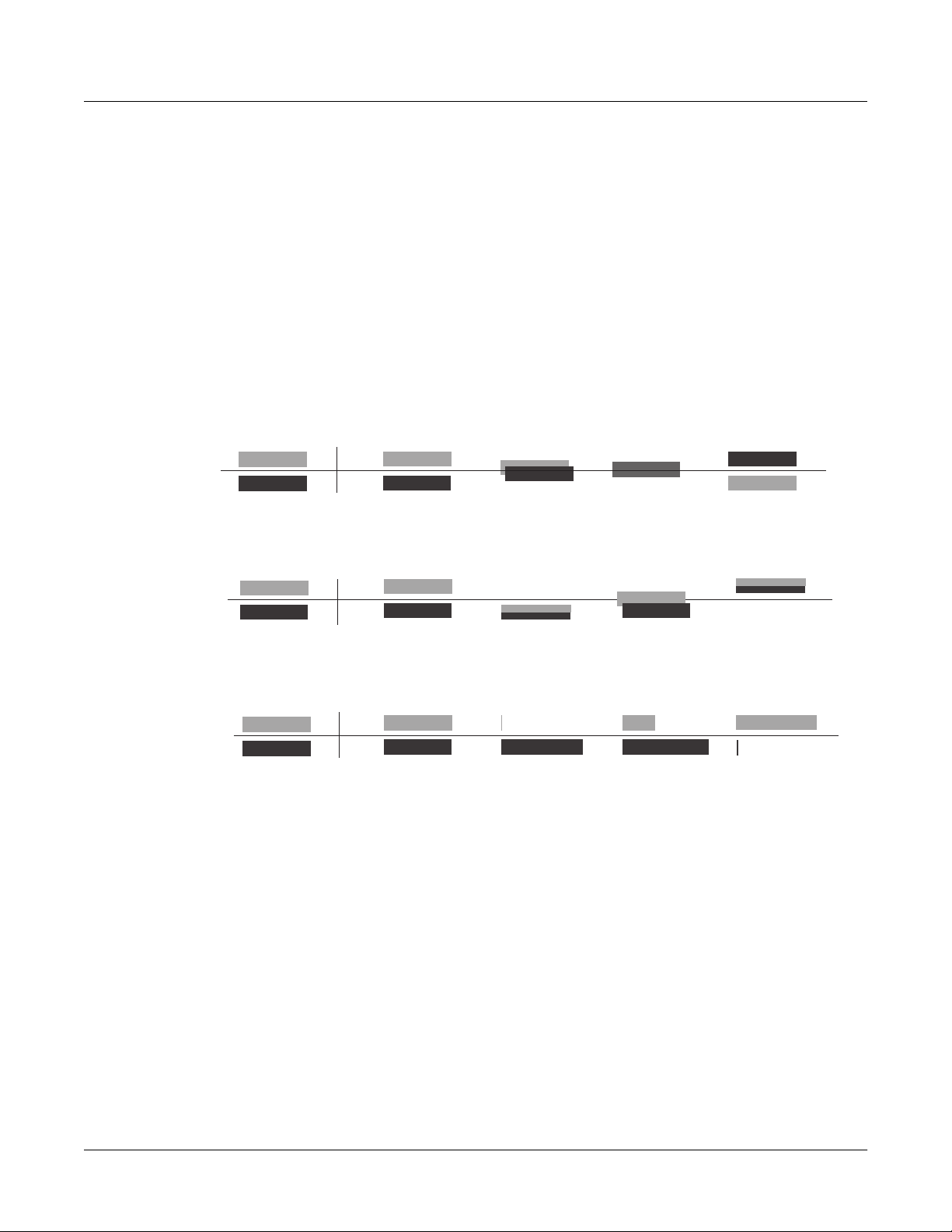
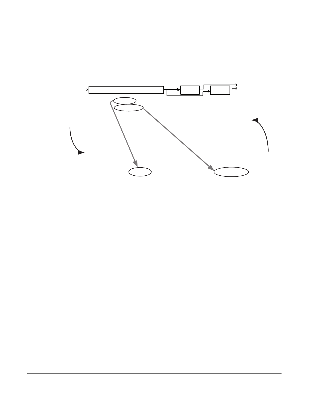
Program 1 Program 2
Studio: Test X
FX1 10 Slo String Hall
Algorithm:5 MiniVerb
if algorithm is the same, transition between FX Presets is smooth
Program 1 Program 2
Studio: Test Y
FX1 11 Orch Hall
Algorithm:5 MiniVerb
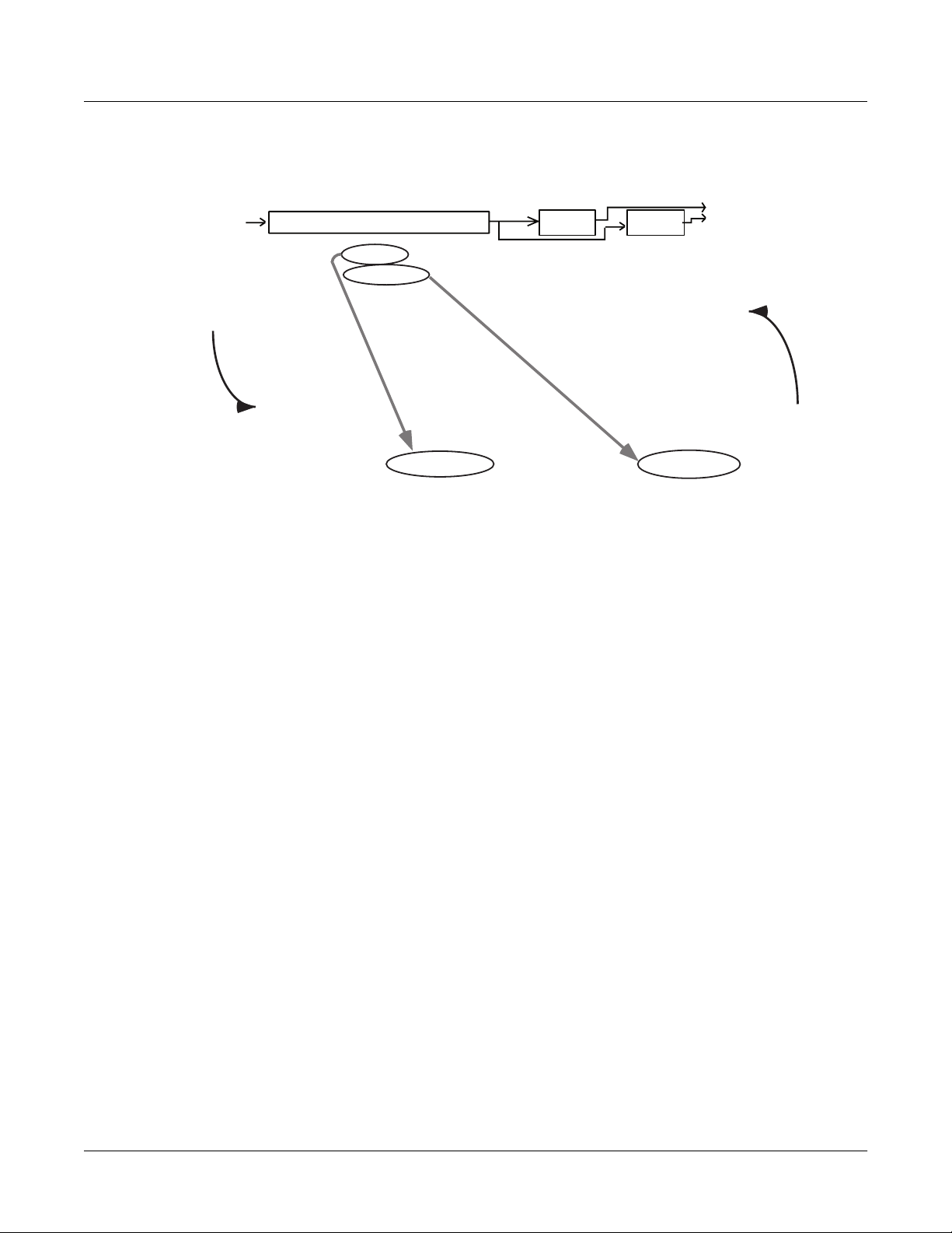
Studio: Test X
FX1 10 Slo String Hall
Algorithm:5 MiniVerb
if algorithm is different, FX Preset output ramps down, then back up
Studio: Test Y
FX1 4 Recital Hall
Algorithm:1 Panaural Room
Figure 15-10 Effect of FX Algorithm on Transition Between FX Presets
Changing PAU Allocations
There are other circumstances under which using the same algorithm will not ensure a smooth
transition. If for any reason the PAUs have to be reallocated when you move from one studio to
another, then even if the algorithms on a given FXBus are the same in both studios, there will be
a ramp-down/ramp-up. This can happen when there is a change in the number of PAUs being
used on any FXBus that has a lower number than the FXBus youÕre concerned with. ThatÕs
because reallocating PAUs on the ßy forces some of the processors to reconÞgure themselves,
inasmuch as they are now being called upon to do different functions.
HereÕs an example: say Studio XÕs FXBus1 uses a Flanger that requires 2 PAUs, while FXBus2
has a small reverb that uses 1 PAU. In Studio Y, FXBus1 has a Chorus that uses only 1 PAU,
while FXBus2 uses the same small reverb as Studio X. When you switch from Studio X to Studio
Y, one of the PAUs that was previously being used for FXBus1 is now being used for FXBus2Ñ
itÕs been reallocated. Since itÕs not the same PAU thatÕs handling the reverb, the transition isnÕt
going to be smoothÑeven though the algorithm hasnÕt changed.
There are a couple of ways around this. First is to set up your studios so that any transitions
between them that are going to force changes in PAU allocations occur in the higher-numbered
FXBusesÑif the situation just described were reversed, and the reverb was in FXBus1, there
would be no problem, because that same PAU would be used in FXBus1 in both studios. A
second method is to manually allocate the PAUs in the lower-numbered FXBuses, rather than
15-31
Page 32

Advanced KDFX
Real-time Control of KDFX
using Auto allocation. Using the same example, if Studio Y had 2 PAUs hard-assigned to
FXBus1, even though the FX preset is only using one of the PAUs, then that second PAU would
not get reassigned to the reverb, and the reverbÕs transition would be smooth.
Studio X
PAU1
PAU2
PAU3
PAU4
FX1 Reverb
PAU1
PAU:1
PAU2
FX2 Flanger
PAU:2
PAU3
PAU4
Either put Multieffects whose PAUs will
change into higher-numbered buses…
FX1 Flanger
PAU:2
FX2 Reverb
PAU:1
If PAUs get re-allocated, transitions won't be smooth
FX1 Reverb
PAU1
PAU:1
FX2 Chorus
PAU2
PAU:1
PAU3
PAU4
Studio Y
PAU1
PAU2
PAU3
PAU4
PAU1
PAU2
PAU3
PAU4
…or use fixed Allocations to prevent
PAUs from being re-assigned
FX1 Chorus
PAU:1
FX2 Reverb
PAU:1
FX1 Flanger
PAU:2
FX2 Reverb
PAU:1
PAU1
PAU2
PAU3
PAU4
FX1 Chorus
PAU:1
FX2 Reverb
PAU:1
15-32
Figure 15-11 Avoiding Transition Problems When PAUs Get Reallocated
Tempo-based Control of KDFX
Many parameters within KDFX can be set up to respond to musical tempo. The tempo
information can come from a number of sources: it can be Þxed within a studio, it can come from
the K2600Õs internal sequencer, or it can come from an external MIDI sequencer that has been
conÞgured to send MIDI Timing Clocks to the K2600.
The procedures for using tempo from the internal sequencer and from an external sequencer are
essentially the same, with one crucial difference in one setting: in Song mode, on the MISC page.
The Clock parameter must be set to Int when using the internal sequencer and to Ext when
using an external sequencer.
Note that MIDI Timing Clocks (otherwise known as MIDI Sync) is not the same as MIDI Time
Code (or MTC). MIDI Sync, which is used for syncing sequencers together, changes its speed in
response to tempo changes; MIDI Time Code, which is used for syncing a sequencer to an audio
or video tape or disk system, does not. KDFX (and the K2600 in general) responds to MIDI Sync,
but not to MIDI Time Code.
Tempo Within an FX Preset
Some algorithms have a Tempo parameter, which allows certain time-based functions, such as
LFOs, envelopes, or delay lengths, to be expressed in beats per minute (BPM). A second
Page 33

Advanced KDFX
Real-time Control of KDFX
parameter immediately below Tempo, Period, multiplies or divides the tempo. The Period is
expressed in beats (bts) and ranges from 1/24 (the actual time is 24 times faster than the Tempo)
to 32 (the time is 32 times slower than the Tempo) in a sliding scale based on 24ths of a beat. So
for example, if an LFO has a Tempo setting of 120 BPM and a Period of 12/24 bts, the LFO will
oscillate 240 times per minute, or 4 Hz.
Variable Tempos Using System
You can also have these parameters respond to tempo in real time, by setting the Tempo
parameter to System, which is set by scrolling below 1 BPM (or pressing 0 and Enter on the
alphanumeric buttonpad). Now instead of Tempo being a Þxed value, it will vary according to
the system clockÑwhich, depending on the setting of the Clock parameter on the Song modeÕs
MISC page as described above, will either be the internal sequencerÕs clock, or tempo coming
from an external source of MIDI Clock. The System Tempo will be multiplied or divided by the
Rate or Beats setting, to determine the parameterÕs actual speed, just as if it were a Þxed value.
If the Clock setting is Int, then the current tempo of the internal sequencer (as shown on the
Song ModeÕs MAIN page) will be in effect regardless of whether the sequencer is running.
If the Clock setting is Ext, the external sequencer (assuming it is sending MIDI Clock) controls
the Tempo parameter. If no MIDI Clock is being received by the K2600, the tempo will not go to
0; instead, it will retain the last valid value it sawÑeither the tempo of the internal sequencer at
the time when you switched the Clock to Ext, or the last tempo sent by an external sequencer
before it stopped.
Tempo as an FXMod Source
KDFX algorithms that donÕt have a Tempo parameter can also respond to tempo information,
using FXMods.
In the Source list, there is a value called Tempo, located at number 55. This source reads the
current tempo (Þxed or variable, internal or external) and turns it into a numerical value
between 0 and 1, which is then applied to the parameter under the control of the FXMod. The
ÒvirtualÓ range of this parameter is 3.75 to 240 BPMÑthat is, a tempo of 3.75 BPM (or less) will
set the parameter value to 0, while a tempo of 240 BPM (or greater) will set it to 1. Of course,
most parameters donÕt actually vary between 0 and 1, so you have to scale the real values
appropriately.
This can get pretty confusing, but there is a relatively simple method to follow when using this
feature: set the Adjust value of an FXMod to the value of the parameter that you want when the
tempo is 3.75 BPM, and set the Depth value so that the sum Adjust+Depth equals the value that
you want when the tempo is 240 BPM.
For example, letÕs look at an algorithm that has an LFO Rate parameter in Hz. LetÕs say we want
to the LFO speed to be twice as fast as the tempo. Here are the values for the FXMod:
Parameter LFO Rate
Adjust The slowest vibrato we want is (3.75 BPM/60) x 2, or 0.125 Hz. 0.13 Hz is the nearest
value available.
Source Tempo
Depth The fastest vibrato we want is (240BPM/60) x 2, or 8.00 Hz, so this parameter is
8.00Ð0.13, or 7.87 Hz; the nearest value available is 7.80 Hz.
The Tempo value exists in Control Source lists throughout the K2600Õs operating system, not just
in FXMod pages, so you can use it for controlling just about any function, including pitches of
sample loops, envelope lengths, Þlters, volume, and more.
15-33
Page 34

Advanced KDFX
Real-time Control of KDFX
T ap Tempo
A real-time tap on a footswitch or button can also be used to control the tempo of a parameter in
KDFX. Like Tempo, Tap Tempo is not KDFX-speciÞc, but can be used throughout the K2600Õs
operating system, including the sequencer.
Tap Tempo is on the Control Source list for any controller in a setup or control setup, located at
number 39. Tapping or pressing on a controller that is set to Tap Tempo sends tempo
information, based on the average time between taps, to the Internal Clock.
It takes four taps to determine the tempoÑif you tap fewer than four times, no information is
sent. If you tap more than four times, the average of all of your taps is continuously calculated
and sent to the Clock. Later taps are weighted more heavily than earlier ones, so that if you
change the rate at which you tap, the tempo information being sent will change accordingly, but
there is a ÒßywheelÓ effect, and the ClockÕs tempo changes will lag somewhat behind the
changes in your tapping rate.
In order for Tap Tempo to have any effect, the Clock parameter on the Song Mode:MISC page
must be set to Internal.
KDFX in Master Mode
So far weÕve been telling you that setting FX Mode to Master on the Effects page disables realtime control over KDFX, but this is not strictly true. In that mode, KDFX will respond to speciÞc
system-exclusive (Sysex) commands. If you are a serious Sysex jockey, you can take advantage
of this by using Sysex commands.
Sysex, in fact, can be used to control KDFX regardless of the FX Mode setting, so if you need to
tweak certain parameters in real time without setting up an FXMod to do it, you can use Sysex
and also use the FXMods in a program or setup.
See Appendix B in the MusicianÕs Reference for details about using SysEx to control KDFX.
KDFX in Auto Mode
When the FX Mode is set to Auto, then control of KDFX changes according to where you take
the K2600: either Program mode or Setup mode. But when you are on the Effects-mode page
itself, you are actually in Master mode. Therefore, you can go into the studio whose name
appears on the page and tweak its parameters, but there wonÕt be any FXMods. You can change
a parameter that has an FXMod link through a program (or setup), but, unlike when you are
going into the studio through a program, that link will not be disturbed.
When you leave the studio, and then go into Program or Setup mode and call up a program or
setup that links to that studio, any changes you have just made in the studio will show up, and
any FXMods previously in place will also still be there.
From Auto Mode to Song Mode
When you are on the Effects-mode page and if FX Mode is set to Auto, and then you go into
Song Mode, something slightly different happens: KDFX is now under control of the program
that is on the effect channel within the songÑfrom Song mode press Edit and look at the
EffectChan parameter.
The effect channel is saved with the song, so make sure that it is set so that the program that you
want to be in control of KDFX is active.
15-34
Page 35

Using the Algorithms
This section will discuss the processing algorithms found in KDFX: what their parameters mean,
and how to use them. It is designed to be read through so that you can get a general
understanding of the algorithms. You can Þnd a more complete reference, with every algorithm
and the meaning and range of every parameter, arranged in the order they appear on the screen,
in the MusicianÕs Reference.
But Þrst, a word about how the KDFX studios in ROM are organized.
Conventional Studio Structure
Many of the studios provided in ROM follow an overall organizational plan, which uses KDFXÕs
resources efÞciently and clearly. While by no means are you required to follow this structure
when creating your own studios, itÕs a good idea to become familiar with it, and see how
KurzweilÕs own engineers have approached the complex issue of studio organization. And
certainly it can serve as a good starting point when you start creating your own studios.
The organization of the ROM studios follows the following guidelines Not all studios are set up
this way, but most of them are.
¥ ROM programs and setups are assigned to an output (KDFX-A through KDFX-D on the
Program:Output or Setup:CH/PRG page) based on the type of effects processing that would
most likely be appropriate for that sound.
Advanced KDFX
Using the Algorithms
¥ All inputs go to their respective FXBuses (Input A to FXBus 1, Input B to FXBus 2, etc.), and
only to their respective FXBusesÑthe Lvl parameter for the second FXBus on each Input
page is turned Off.
¥ FXBus1 contains a relatively simple reverb with a low Size requirement.
¥ FXBus2 contains an effect that does not increase the ÒlengthÓ of the sound (that is, no reverb
or delay). Possibilities include chorus, ßange, phaser, distortion, shaper, pitcher, enhancer,
EQ, or EQ morpher.
¥ FXBus3 contains effects that take up lots of time, such as delays, delays with reverb, or other
lead sounds.
¥ FXBus4 is dry, since the Þrst three FXBuses have probably used up all the PAUs.
¥ The Aux bus contains a larger reverb (Size: 2 or 3), a compressor, or a graphic EQ. It can
often be used instead of an FXBus reverb, such as the one on FXBus1. If you use it in this
way (set the Aux Lvl on FXBus1 to 0dB or higher), it frees up FXBus1 for use as an Enhancer,
Stereo Image, Flanger, etc.
General Parameters
Some parameters show up in all algorithms, and weÕll deal with those Þrst.
Wet/Dry balances the levels of the processed and unprocessed signals passing through the
FXpreset. The range is 0% wet (the signal is unprocessed) through 100% wet (no dry signal is
present). A setting of 50% wet means the dry and processed signals are equal in level. In some
algorithms, separate Wet/Dry parameters are provided for the Left and Right input channels.
In Gain sets the level of the signal coming into the FXpreset from the Input page. As with most
Gain controls in KDFX, the range is -79.0 dB to 24.0 dB, and there is an Off position. 0.0 dB is
unity gain.
15-35
Page 36

Advanced KDFX
Using the Algorithms
Out Gain sets the level of the signal after it passes through the FXpreset. From here the signal
goes directly to the Output page, if one of the Outputs is set to FXBusn. The level can be further
changed before it goes to the Mix and/or Aux buses.
In/Out enables or disables the effect. ItÕs like a Wet/Dry parameter with only two positions:
100% (In) and 0% (Out).
HF Damping is the cutoff (-3 dB) frequency of a 6dB/octave lowpass Þlter thatÕs inserted before
the processor. In the case of processors where multiple iterations of the signal are heard, such as
in a delay, each iteration of the signal will pass through the Þlter, and will therefore be duller.
XCouple (Cross Couple). In stereo effects, this controls how much of any signal that is being fed
back goes to the channel opposite to the one where it Þrst appeared. At 100%, all feedback from
signals at the left input goes to the right channel, and vice versa, causing a ÒspreadingÓ or in the
case of delay lines, a ping-pong effect. At 0%, fed-back signals stay with the channel they came
in on.
A->B cfg (conÞguration). In combination algorithms that contain two components, and whose
name uses <>, as in 713 Flange<>Shaper, the order in which the signal passes through the two
components can be changed. For example, this algorithm can be conÞgured so the signal passes
through the reverb Þrst and then the compressor, or through the compressor Þrst and then the
reverb. The A->B cfg parameter determines the conÞguration, and its value is contextsensitiveÑin this example, the choices would be Rvb->Cmp and Cmp->Rvb.
A/Dry->B is also found in many combination algorithms, and controls the amount of signal that
will pass dry (unprocessed) through the Þrst component into the second component. Different
combination algorithms use different variations on this parameter, depending on the context.
The range is 0 to 100%.
Reverbs
Room Type changes the conÞguration of the algorithm to simulate a wide array of room types
and sizes including booths, small rooms, chambers, halls and large spaces can be selected. Use
this parameter to choose different types of reverbÑif all other parameters remain at their
nominal values, what you get when you change this parameter will always sound great.
Because this parameter changes the structure of the reverb algorithm, it cannot be assigned an
FXMod. Room types in different algorithms with similar names do not necessarily sound the
same.
Rvrb Time is the RT60Ñthe time it takes for the reverb to decay to 60 dB below its initial levelÑ
in seconds. It is accurate assuming that several other parameters (HF Damping, Diff Scale, Size
Scale, and Density) are at their nominal levels. It is adjustable up to Inf, which creates an
inÞnitely-sustaining reverb.
LateRvbTim adjusts the basic decay time of the late portion of the reverb after diffusion.
L/R Pre Dly (PreDelay) is the time between the start of a sound and the output of the Þrst reverb
reßections from that sound. Longer predelays can help make larger spaces sound more realistic.
Longer times can also help improve the clarity of a mix by separating the reverb signal from the
dry signal, so the dry signal is not obscured.
15-36
EarRef Lvl adjusts the mix level of the early reßection portion of algorithms offering early
reßections.
Late Lvl adjusts the mix level of the late reverb portion of algorithms offering early reßections.
Diff Scale scales the diffusion of the early reßections, that is, how spread out they are as a group
over time. At very low settings, the early reßections start to sound quite discrete, and at higher
Page 37

Advanced KDFX
Using the Algorithms
settings the early reßections are seamless. It is adjustable from 0.00 to 2.00, with 1.00 being
nominal for the given Room Type.
Density controls how tightly the early reßections are packed in time. Low Density settings
group the early reßections close together, while higher values spread the reßections for a
smoother reverb. It is adjustable from 0.00 to 4.00, with 1.00 being nominal (and usually optimal)
for the given Room Type.
Expanse controls the amount of late reverb energy biased toward the edges of the stereo image.
A setting of 0% will bias energy towards the center. Moving away from 0% will bias energy
towards the sides. Positive and negative values will have a different character.
Build adjusts the envelope of certain portions of the reverb. Positive values speed up the
envelope, and negative values slow it down.
Size Scale changes the size of the current room. Altering this parameter will cause a subtle
coloration of the reverb. It is adjustable from 0.00 to 4.00, with 1.00 being nominal (and usually
optimal) for the given Room Type.
InÞnDecay, when set to On, causes the reverb tail to decay indeÞnitely. When itÕs Off, the decay
time is determined by the Rvrb Time or LateRvbTim parameters.
Wet Bal (Wet Balance). Some reverb algorithms are actually two stereo reverbs in one, with each
one receiving a different mono signal. This balances the outputs of the two reverbsÑ0% means
they are being mixed equally.
Delays
There are two types of taps in the Multitap delays: The Loop tap, which can be repeated, and the
numbered taps, which play a single iteration.
Fdbk (Feedback) Level controls the repeating function of the Loop Tap. A setting of 0% means
there will only be a single delay, while a setting of 100% means the signal keeps repeating
without ever stopping.
Both types of taps are individually adjustable from 0 to 2.55 seconds. The Loop Crs and Tapn Crs
(n being the number of the tap) parameters set the coarse value of the loop in 20-ms increments,
while the Loop Fine and Tapn Fine parameters set the Þne value in 0.2-ms increments.
In Delay algorithms that use tempo to determine tap lengths, there is a Tempo parameter, which
can be set from 1 to 255 BPM or to System. The Loop Length and Tapn Delays are then
expressed in beats relative to that overall Tempo. See Tempo-based Parameters on page 15-25 for
more information about tempo control of KDFX parameters.
Hold is a switch that, when turned on, ÒlocksÓ any signal currently in the delay and plays it
until Hold is turned off. When Hold is on, no signal can enter the delay and Feedback is set to
100%.
Dry Bal (Balance) is the left/right balance of the dry signal. At -100%, only the left dry signal
goes to the left output, while at 100% only the right dry signal passes to the right output, and at
0%, equal amounts of the left and right dry signals pass to their respective outputs.
Ta p n Level is the level of each numbered tap, from 0% to 100%, relative to the overall output of
the effect.
Ta p n Bal is the left/right balance of each of the numbered taps. At -100%, only the left tap goes
to the left output, while at 100% only the right tap goes to the right output, and at 0%, equal
amounts of the left and right taps pass to their respective outputs. In some delays, pairs of taps
(1 and 5, 2 and 6, etc.) are controlled together as stereo pairs.
15-37
Page 38

Advanced KDFX
Using the Algorithms
Complex Echo
DelayScale lets you change the lengths of all the taps together. Its range is 0 to 10x.
Note that it is possible for KDFX to run out of delay memory with over-generous settings of DelayScale
or very slow Tempos. If this happens, delay times will be automatically cut in half.
This algorithm has two feedback taps per channel as well as three independent taps, and also a
feedback diffuser for ÒsmearingÓ the delays. Feedback line 1 feeds the signal back to the delay
input of the same channel, while feedback line 2 feeds the signal back to the opposite channel.
FB2/FB1>FB is a balance control between feedback lines 1 and 2. 0% (minimum) turns off
feedback line 2, only allowing use of feedback line 1. 50% is an even mix of both lines, and 100%
(maximum) turns off line 1.
L Diff Dly and R Diff Dly adjusts the delay lengths of the diffusers. Range is 0 to 100 ms.
Diff Amt adjusts the diffuser intensity. Range is 0 to 100%.
N Fdbkn Dly adjusts the delay length of the N channelÕs nth feedback tap, fed back to the
N channelÕs delay input. Range is 0 to 2600 ms.
Spectral Multitap Delays
These 4- and 6-tap delays have their feedback and output taps modiÞed with shapers and Þlters.
In the feedback path of each tap are a diffuser, hipass Þlter, lopass Þlter, and imager. Each delay
tap has a shaper, comb Þlter, and balance and level controls.
Fdbk Image sets the amount the stereo image is shifted each time it passes through the feedback
line. Range is -100 to 100%.
Ta p n Shapr adjusts the intensity of the shaper at each output tap. Range is 0.10 to 6.00 x.
Ta p n Pitch adjusts the frequency of the comb Þlter at each output tap. Range is C -1 to C 8, in
semitones.
Ta p n PtAmt adjusts the intensity of the comb Þlter at each output tap. Range is 0 to 100%.
Equalizers (EQ)
KDFX has both Graphic and Parametric EQ algorithms. Parametric EQ sections are also
available on a number of combination algorithms.
The Graphic equalizer is available as stereo (linked parameters for left and right) or dual mono
(independent controls for left and right). It has 10 bandpass Þlters per channel, each of whose
gain is adjustable from -12 dB to +24 dB.
Like all graphic equalizers, the Þlter response is not perfectly ßat when all gains are set to the
same level (except at 0 dB), but rather has ripple from band to band. To minimize this ripple, it is
best to center the overall settings around 0 dB.
15-38
The Parametric equalizer (5-Band EQ) has two bands of shelving Þlters and three bands of true
parametric EQ.
Treb Freq and Bass Freq set the center frequencies for the shelving Þlters. Both of these are
adjustable over the full range of 16 to 25088 Hz, in increments of a semitone.
Page 39

Advanced KDFX
Using the Algorithms
Treb Gain and Bass Gain control the amount of cut or boost above (Treb) or below (Bass) the
center frequency. The range is -79 to +24 dB.
Midn Gain sets the cut or boost for the parametric band n, with a range of -79 to +24 dB.
Midn Freq sets the center frequency for parametric band n, with a range of 16 to 25088 Hz, in
increments of a semitone.
Midn Width sets the bandwidth of the Þlter on band n, with a range of 0.01 to 5 octaves.
Enhancers
Enhancers modify the spectral content of the input signal by boosting existing spectral content,
or stimulating new ones. Two- and three-band versions are provided.
Drive adjusts the input into each band. Increasing the drive will increase the effects. Range is
-79.0 to 24.0 dB.
Xfer adjusts the intensity of the transfer curves. Range is -100 to 100%.
EQ Morpher
This algorithm uses two four-band bandpass Þlters, A and B, and moves between them, which
among other things, can produce a very convincing simulation of a human vocal tract.
FreqScale offsets the Þlter frequencies for each set of Þlters. After setting the Þlter parameters
(Freq, Gain, and Width), the FreqScale parameters will move each of the four Þlter frequencies
together by the same relative pitch. Range is -8600 to 8600 cents.
Morph A>B. When set to 0% the A parameters are controlling the Þlters, and when set to 100%,
the B parameters control the Þlters. Between 0 and 100%, the Þlters are at interpolated positions.
When morphing from A to B settings, the A Þlter #1 will change to the B Þlter #1, A Þlter #2
moves to B Þlter #2, and so on. Range is 0 to 100%.
Compressors, Expanders, and Gates
A wide range of Compression and Expansion effects is available in KDFX. The various
algorithms include different combinations of:
¥ Compressor with either soft-knee or hard-knee characteristic
¥ Expander
¥ Multiband compressor that breaks the signal up into three frequency bands and compresses
them all separately
¥ Sidechain or output EQ
¥ Reverb and compressor in combination
¥ Gate
¥ Gated reverb
All of the compression algorithms use these parameters:
FdbkComprs (Feedback Compression) selects whether to use feed-forward (set this to Out) or
feedback (set this to In) compression. The feed-forward conÞguration uses the input signal as
the side-chain source. The feedback conÞguration uses the compressor output as the side-chain
15-39
Page 40

Advanced KDFX
Using the Algorithms
source. Feedback compression tends to be more subtle, but it does not allow instantaneous
attack compression.
Atk (Attack) Time for the compressor is adjustable from 0.0 to 228.0 ms.
Rel (Release) Time for the compressor is adjustable from 0 to 3000 ms.
Smooth Time smooths the output of the expanderÕs envelope detector by putting a lowpass
Þlter in the control signal path. Smoothing will affect the Attack or Release times only when this
parameter is longer than one of the other times. The range is 0.0 to 228.0 ms.
Signal Dly (Delay) puts a small delay in the signal relative to the sidechain processing, so that
the compressor (or gate) ÒknowsÓ what the input signal is going to be before it has to act on it.
This means the compression can kick in before an attack transient arrives. In a compressor, it is
only really useful in feedback conÞguration (FdbkComprs is In). The range is 0 to 25 ms.
Ratio is the amount of gain reduction imposed on the compressed signal, adjustable from 1.0:1
(no reduction) to 100:1, and Inf:1.
Threshold is the level in dBFS (decibels relative to full scale) above which the signal begins to be
compressed. Adjustable from -79.0 to 0 dB.
MakeUpGain allows additional output gain to compensate for gain reduction in the
compressor. It works in conjunction (additive, in dB) with the Out Gain parameter. The range is
-79.0 to +24.0 dB.
Expansion
Algorithms containing Expanders have these controls:
Exp Atk (Attack), how fast the expander turns off when the input signal rises above the
threshold level, adjustable from 0.0 to 228.0 ms.
Exp Rel (Release), how fast the expander turns back on after the signal drops below the
threshold level, adjustable from 0 to 3000 ms.
Exp Ratio, how much the gain is reduced below the expansion threshold, adjustable from 1:1.1
(slight downward expansion) to 1:17 (extreme downward expansion).
Exp Threshold, the level below which the signal is expanded, adjustable from -79.0 to 0 dB.
In addition, the two-segment compressors with expander have separate Ratio and Threshold
controls for each of the compression segments.
Multiband Compression
The Multiband Compression algorithm has Attack, Release, Smooth, Signal Delay, Ratio,
Threshold, and MakeUp Gain parameters for each of the three bands (Low, Mid, and High). In
addition, it has the following:
Crossover1 and Crossover2. These set the frequencies which divide the three compression
frequency bands. The two parameters are interchangeable, so either may contain the higher
frequency value. The range is 16 to 25088 Hz, in increments of a semitone.
15-40
Gates
SC Input lets you select which input channel(s) will control the sidechain, which is responsible
for opening and closing the gate. It can be set to L, R, or the average of the two channels,
(L+R)/2.
Page 41

Chorus
Advanced KDFX
Using the Algorithms
Gate Time is the time that the gate will stay open when the sidechain signal reaches the
Threshold. Its range is 0 to 3000ms.
Ducking reverses the action of the gate. Normally this if set to Off, and the gate opens when the
input signal rises above the threshold. But when this is On, the gate closes when the input signal
rises above the threshold.
Env Time is the amount of time it takes for the sidechain signal envelope to drop below the
threshold. If this time is too short, the gate can close and open too quickly from amplitude
modulation in the sidechain signal. If it is too long, the gate may stay closed until the envelope
has a chance to fall, and some signals would not get through. This parameter is only in effect
when Retrigger is Off.
Retrigger determines whether the gate timer will reset itself each time the sidechain signal goes
above the threshold. If it is On, the timer resets itself, and therefore the gate stays open as long as
the signal is above the threshold, or keeps going above the threshold, within the interval
speciÞed by Gate Time. If it is Off, the gate closes down after Env Time has elapsedÑregardless
of the sidechain levelÑand the sidechain level must fall below the threshold and come back up
again before the gate will open again.
Chorus is an effect that gives the illusion of multiple voices playing in unison. The effect is
achieved by detuning copies of the original signal and summing the detuned copies back with
the original. Low frequency oscillators (LFOs) are used to modulate the positions of output taps
from a delay line. The delay line tap modulation causes the pitch of the signal to shift up and
down, producing the required detuning.
The choruses are available as stereo or dual mono. The stereo choruses have the parameters for
the left and right channels ganged, while the dual mono choruses have separate left and right
controls.
Fdbk Level is the level of the feedback signal from the LFO1 delay tap into the delay line.
Negative values polarity-invert the feedback signal.
Tap Lvl sets the levels of the LFO-modulated delay taps. Negative values polarity-invert the
signal. Setting any tap level to 0% effectively turns it off.
Tap Pan sets the stereo position for a given tapÕs output. The range is -100% for fully left to 100%
for fully right.
LFO Rate sets the speed of modulation of the delay lines with a range of 0.01 to 10 Hz.
LFO Dpth sets the maximum detuning depth of the LFO-modulated delay lines, with a range
from 0 to 50 cents (1/2 semitone).
Tap Dly adds extra delay in front of the LFO modulated delay taps from 0 to 230 ms.
L/R Phase or LFOn LRPhs adjusts the relative phases of the LFOs for the left and right channels
in the stereo Choruses.
15-41
Page 42

Advanced KDFX
Using the Algorithms
Flanger
Flanging is the process of adding or subtracting a signal with a time-displaced replica of itself,
which results in a series of notches in the frequency spectrum, generally referred to as a comb
Þlter. In KDFX, the ßanger is a multi-tap delay line, all (but one) of whose taps can have their
lengths modulated up and down by a low frequency oscillator (LFO). The rate of the LFO is
expressed in Tempo.
StatDlyLvl (Static Delay Level) is the level of the Þrst, nonmoving tap. Negative values invert
the polarity of the tap. The range is -100 to 100%; 0% turns the tap off.
DlyCrs and DlyFin are the coarse and Þne length controls for the Static delay (StatDlyÉ) and
for the minimum value of the moving delays (DlynÉ). The coarse range is 0 to 228 ms, and the
Þne range adjusts the coarse range in samples (1/48,000 sec, or 20.8µsec) from -127 to 127.
Xcurs Crs and Xcrs Fin determine how far the LFO-modulated delay taps can move from the
center of their ranges (this is called excursion). The total range of the LFO sweep is twice the
excursion. If the excursion is set to 0, the LFO does not move and the tap behaves like a simple
delay line set to the minimum delay. The coarse range is 0 to 228 ms; the range 0 to 5 ms is most
effective for ßanging. The Þne range adjusts the coarse range in samples from -127 to 127.
Quantize + Flange
The Quantize portion of this algorithm produces digital distortion known as quantization noise
by limiting the number of bits available to the signal.
DynamRange (dynamic range) controls how many bits to remove from the signal data words.
At 0 dB the hottest of signals will toggle between only two bit (or quantization) levels, thereby
producing a square wave. Every 6 dB added doubles the number of quantization levels,
reducing the noise and getting closer to the original signal. If the signal has a lot of headroom
(available signal level before digital clipping), then not all quantization levels will be reached.
Range is 0 to 144 dB.
Headroom sets the available signal level before digital clipping. Use this in conjunction with
DynamRange to keep the signal level from getting too loud at low levels of DynamRange.
Range is 0 to 144 dB.
DC Offset adds a positive DC Offset to the input signal, which allows you to alter the position
where digital zero is with respect to your signal. At low DynamRange settings, this can cause
the output to sputter. Range is Off/-79.0 to 0.0 dB.
LaserVerb
LaserVerb is a new kind of reverb which produces a delayed train of closely spaced reßections,
or impulses. As time passes, the spacing between the impulses gets wider, which creates a
discernible buzzy pitch that gets lower as the spacing increases. The signal can be fed back into
itself to extend the effect.
Dly Coarse is the overall delay length, which controls the duration or decay time. 0.5 sec is a
good starting point. Range is 0 to 1.3 seconds in the 2 PAU version of the algorithm, and 0 to
2 seconds in the 3-PAU version.
Dly Fine adjusts the delay with a resolution down to 0.1 ms. Range is -20.0 to 20.0 ms.
15-42
Spacing determines the starting pitch of the descending buzz and how fast it descends, by
setting the initial separation of impulses and the subsequent rate of increasing impulse
separation. The spacing between impulses is given in samples (20.8µs), with a resolution of 0.1
Page 43

Filters
Advanced KDFX
Using the Algorithms
sample. At low values, the buzz starts at high frequencies and drops slowly, while at high values
the buzz starts at a lower pitch and drops rapidly. Range is 0.0 to 40.0 samples.
Contour controls the overall shape of the reverb. When set to a high value, sounds passed
through the reverb start at a high level and slowly decay. As the control value is reduced, it takes
more time for the effect to build up before decaying. At a value of around 34, the reverb behaves
like a reverse reverb, building up to a hit. When it is set to 0, the algorithm acts like a simple
delay. Range is 0 to 100%.
There are four types of Resonant Filter algorithms in KDFX.
Resonant Filter
Filter Type (FiltType) can be Lowpass, Highpass, Bandpass, or Notch (band-limit).
Frequency (Freq) is the resonant frequency of the Þlter. Its range is 58 to 8372 Hz.
Resonance is the resonance of the Þlter, adjustable from 0 to 50 dB.
Envelope Filter
Envelope Filter is a resonant Þlter whose center frequency can be made to vary according to the
level of the incoming signal.
Filter Type can be Lowpass, Highpass, Bandpass, or Notch (band-limit).
Min Freq is the minimum resonant frequency of the Þlter, that is, the Þlter frequency when the
input gain is below the triggering threshold. Its range is 58 to 8372 Hz.
Sweep determines how far the resonant frequency moves when the input level increases. At
positive levels it moves up in pitch, and at negative levels it moves down. The highest possible
resonant frequency is 8372 Hz,; the lowest is 0 Hz. This parameterÕs range is -100% to +100%.
Resonance is the resonance of the Þlter, adjustable from 0 to 50 dB.
Atk Rate adjusts the upward slew of the attack portion of the envelope detector. Range is 0 to
300.0 dB/sec.
Rel Rate adjusts the downward slew of the release portion. Range is 0 to 300.0 dB/sec.
Smooth Rate slows down the envelope follower. If it is set to a lower rate than Atk Rate or Rel
Rate, it can dominate those parameters. Range is 0 to 300.0 dB/sec.
Trig Filt
The Triggered Filter is a sweeping resonant Þlter that triggers when a certain input threshold is
reached, and then follows its own envelope, consisting of an instantaneous attack and an
exponential release, rather than the envelope of the input signal.
Max Freq is the resonant frequency of the Þlter at the peak of the internal envelope. It can be set
lower than Min Freq (above), in which case the Þlter will sweep downwards, then back up.
Range is 58 to 8372 Hz.
Trigger is the input-signal threshold at which the envelope detector triggers. Range is -79 to
0 dB.
15-43
Page 44

Advanced KDFX
Using the Algorithms
Retrigger is the input-signal threshold at which the envelope detector resets, so that it can
trigger again. This parameter is only useful when it is set below the value of Trigger. Range is
from -79 to 0 dB.
Env Rate is the envelope detector decay rate. This can be used to prevent false triggering. When
the signal envelope falls below the retrigger level, the Þlter can be triggered again when the
signal rises above the trigger level. Since the input signal can ßuctuate rapidly, it is necessary to
adjust the rate at which the signal envelope can fall to the retrigger level. The range is 0 to
300.0 dB/sec.
Rel Rate is the downward slew (release) rate of the triggered envelope generator. The range is 0
to 300.0 dB/sec.
Smth Rate slows down the envelope follower. If set lower than the release rate, it will dominate
it. You can also use the smoothing rate to lengthen the attack of the internal envelope. The range
is 0 to 300.0 dB/sec.
LFO Filter
The LFO Þlter is continuously swept between two resonant frequencies over a period of time.
The LFO frequency, expressed in BPM and beats, can be Þxed or set to follow System tempo.
(See Tempo-based Parameters on page 15-25for more information about tempo control of KDFX
parameters.)
Min Freq and Max Freq are the low and high limits of the resonant frequency as the Þlter is
swept. It actually doesnÕt matter which is higher; the effect will be the same. The range for both
is 58 to 8372 Hz.
LFO Shape is the waveform type for the LFO. Choices are Sine, Saw+, Saw-, Pulse, and Tr i.
LFO PlsWid (Pulse Width). When the LFO Shape is set to Pulse, this sets the pulse width as a
percentage of the waveform period. When the width is set to 50%, the result is a square wave.
This parameter has no effect if other waveform types are chosen. Range is 0 to 100%.
LFO Smooth smooths (removes the higher harmonics from) the Saw+, Saw-, and Pulse
waveforms. A Sawtooth wave looks more like a triangle wave, and a Pulse wave looks more like
a sine wave. Range is 0 to 100%.
Distortion
Distortion algorithms on KDFX may include a parametric equalizer or a cabinet simulator.
Dist Drive applies a boost to the input signal to overdrive the distortion algorithm into soft
clipping. Since distortion drive will make your signal very loud, you may have to reduce the
Out Gain as the drive is increased. Range is 0 to 96 dB.
Warmth is a lowpass Þlter in the distortion control path. This Þlter may be used to reduce some
of the harshness of some distortion settings without reducing the bandwidth of the signal.
Range is 16 to 25088 Hz.
Highpass allows you to reduce the bass content of the distortion content in the smaller
distortion algorithms that donÕt have true parametric EQ. Range is 16 to 25088 Hz.
15-44
Cab Preset selects from eight cabinet simulations which have been created based on
measurements of real guitar ampliÞer cabinets. The presets are: Plain, Lead 12, 2x12, Open 12,
Open 10, 4x12, Hot 2x12, and Hot 12.
Cab Bypass switches on and off the cabinet-simulation part of the algorithm. When this is set to
In, the cabinet simulation is active; when it is Out, there is no cabinet Þltering.
Page 45

Cabinet HP and Cabinet LP are highpass and lowpass Þlters to set the frequency response
limits of the cabinets. Range of both Þlters is 16 to 25088 Hz.
Polydistort
This is a more complex distortion algorithm that provides two, four, or six stages of distortion.
Curve n controls the curvature of the individual distortion stages. 0% is no curvature (no
distortion at all). At 100%, the curve bends over smoothly and becomes perfectly ßat right
before it goes into clipping. Maximum value is 127%.
LP n Freq are shelving frequencies for one-pole lowpass Þlters on each of the distortion stages.
LP0ÊFreq handles the initial low pass prior to the Þrst distortion stage. The other low pass
controls follow their respective distortion stages. Range is 16 to 25088 Hz.
Rotating Speakers
An algorithm that includes Rotating Speakers breaks the signal into two frequency bands,
ÒrotatesÓ each band separately through a virtual speaker, and then combines the outputs with a
pair of virtual ÒmicrophonesÓ whose angle relative to the speakers is adjustable.
Xover (Crossover) is the frequency at which high and low frequency bands are split and sent to
separate rotating drivers. The range is 16 to 25088 Hz.
Advanced KDFX
Using the Algorithms
Lo Gain and Hi Gain are the gains of the signal passing through the rotating woofer or tweeter,
respectively. The range is Off/-79.0 to 24.0 dB.
Lo Rate and Hi Rate are the rotation rates of the rotating woofer and tweeter. Each driver
woofer can rotate clockwise or counter-clockwise, which is determined by the sign of this
parameter: assuming the microphones are positioned in front of the driver and the microphones
are panned positively (positive numbers go to the right), then a positive value for this parameter
causes the driver to spin clockwise when viewed from the top. The range is -10.00 to 10.00 Hz.
Lo Size and Hi Size are the effective sizes (radius of rotation) of the rotating speakers in
millimeters. This affects the amount of Doppler shift or vibrato of the low frequency signal. The
range is 0 to 250 mm.
Lo Trem and Hi Trem control the depth of tremolo (amplitude modulation) of the signals. It is
expressed as a percentage of full scale tremolo. The range is 0 to 100%.
Mic Angle is the angle of the virtual microphones in degrees from the ÒfrontÓ of the rotating
speaker. For the left microphone the angle increases clockwise (when viewed from the top),
while for the right microphone the angle increases counter-clockwise. You should not assign an
FXMod to this parameter because adjustments to it will result in large sample skips, which will
cause clicks in the signal passing through. The range is 0 to 360.0 degrees.
LoResonate and HiResonate are simulations of cabinet resonant modes express as a percentage.
For realism, you should use very low settings. The range is 0 to 100%.
Lo Res Dly and Hi Res Delay are the number of samples of delay in each resonator circuit in
addition to the rotation excursion delay. The range is 10 to 2550 samples.
LoResXcurs and HiResXcurs are the number of samples of delay to sweep through the
resonator at the rotation rate of each rotating speaker. The range is 0 to 510 samples.
ResH/LPhs sets the relative phases of the high and low resonators. The angle value in degrees is
somewhat arbitrary and you can expect the effect of this parameter to be rather subtle. The
range is 0 to 360.0 degrees.
15-45
Page 46

Advanced KDFX
Using the Algorithms
Vibrato/Chorus
The Vibrato/Chorus algorithm (and also the KB3 effects algorithm) simulates the vibrato and
chorus effects on a Hammond organ, and is used in conjunction with the Rotary Speaker. It has
several unique parameters:
VibChInOut is an in/out switch for the Vibrato/Chorus effect.
Vib/Chor is the type of Vibrato/Chorus effect to be used. The choices are from three vibratos,
V1, V2, V3, or three choruses, C1, C2, C3.
Roto InOut engages or bypasses the rotary speaker effect.
Lo Beam W and Hi Beam W set the acoustic radiation patterns (beam width) of the two drivers
in the rotating speaker. If you imagine looking down on the rotating speaker, this angle is the
angle between the -6 dB levels of the beam. The range is from 45¡ to 360¡. At 360¡, the driver is
omnidirectional.
There are four virtual microphones, with two each on the woofer (LoMic A and LoMic B) and
on the tweeter (HiMic A and HiMic B). Each microphone has the following parameters:
¥ Pos (position), the angle of the microphone from the front of the virtual speaker, from -180 to
180 degrees
¥ Lvl (level) from 0 to 100%
¥ Pan, the left/right panning of the microphoneÕs output, from -100% (full left) to 100% (full
right)
Tremolo and AutoPan
Tremolo is amplitude modulation using an LFO. AutoPan moves the signal between the left and
right channels, using an LFO. They have several parameters in common and several unique
parameters.
LFO Rate is the rate of the LFO. The range is 0 to 10.00 Hz, or in Tremolo BPM algorithm, 0 to
12.00 x the tempo.
Rate Scale multiplies the speed of the LFO rate into the audio range. The range is 1 to 25088 x.
When above 19x, the values increment in semitone steps. These steps are accurate when LFO
Rate is set to 1.00 Hz.
LFO Shape is the waveform type for the LFO. Choices are Sine, Saw+, Saw-, Pulse, and Tr i.
LFO PlsWid or Pulse Width: When the LFO Shape is set to Pulse, this sets the pulse width as a
percentage of the waveform period. When the width is set to 50%, the result is a square wave.
This parameter has no effect if other waveform types are chosen. Range is 0 to 100%.
Origin (AutoPan) determines the axis for the panning motion. At 0%, the panning is centered
between the speakers. Positive values shift the axis to the right, while negative values shift it to
the left. At -100% or +100% (the range limits), there is no panning action.
ImageWidth (AutoPan) is the width of the original input program material before it is autopanned. At 0% (minimum), the input image is shrunk to a single point source, allowing
maximum panning excursion. At 100% (maximum), the original width is maintained so no
panning can occur.
15-46
Pan Width (AutoPan) controls the amount of pan excursion. It is the percentage of total panning
motion available after Origin and ImageWidth are set. Range is 0 to 100%.
Page 47

CentrAtten (Attenuation) (AutoPan) is the amount the signal level drops as it is panned through
the center of the stereo image. For the smoothest tracking, a widely accepted subjective reference
is -3dB. Values above -3dB will cause somewhat of a bump in level as an image passes through
the center, while values below -3dB will cause a dip. Range is -12 to 0 dB.
Depth (Tremolo) controls the amount of attenuation applied when the LFO is at its deepest
excursion point. Range is 0 to 100%.
LFO Phase (Tremolo BPM) shifts the phase of the tremolo LFO relative to the beat reference. It is
most useful when Tempo is set to System. Range is 0.0 to 360.0 degrees.
50% Weight (Tremolo) is the relative amount of attenuation added when the LFO is at the -6dB
point. This causes the LFO shape to bow up (positive values) or down (negative values). Range
is -16 to 3 dB.
L/R Phase sets the phase relationship of the channels. In ßips the left channelÕs LFO out of
phase, with the result that the effect turns into an auto-balancer. Out leaves the left LFO alone.
Pitch Shifter (Pitcher)
Pitcher shifts the pitch of the incoming signal to the speciÞed note.
Pitch is the fundamental pitch imposed upon the input, in MIDI note numbers from C -1 to G 9.
Advanced KDFX
Using the Algorithms
Ptch Offst is an offset from the pitch frequency in semitones, from -12.0 to 12.0. It can be useful
to assign pitch bend or a continuous controller to this parameter through an FXMod.
Odd Wts, Pair Wts, Quartr Wts, Half Wts are parameters that control the exact shape of the
frequency response of Pitcher. An exact description of what each one does is, unfortunately,
impossible, since there is a great deal of interaction between them. For more information and
examples, see the algorithm documentation.
Ring Modulation
Ring modulation multiplies two signals (the ÒcarrierÓ and the ÒmodulatorÓ) together to produce
unusual, often nonharmonic, overtones. The Ring Modulator algorithm in KDFX has two
modes: L*R, in which two mono signals are modulated together; and Osc, in which the input is
stereo, and it is modulated with the sum of Þve waveforms which are generated within the
algorithm itself. Four of these are sine waves, and one (Oscillator 1) has a conÞgurable
waveform.
Wet/Dry: In L*R mode, the left signal is passed dry through this control.
Mod Mode selects between the two modes.
Osc1 Lvl is the level of Oscillator 1, from 0 to 100%.
Osc1 Freq is the frequency of Oscillator 1, from 16 to 25088 Hz.
Osc1 Shape is the waveshape of Oscillator 1, selectable from Sine, Saw+, Saw-, Pulse, and Tr i.
Osc1PlsWid (Pulse Width). When Osc1 Shape is set to Pulse, this sets the pulse width as a
percentage of the waveform period. When the width is set to 50%, the result is a square wave.
This parameter has no effect if other waveform types are chosen. Range is 0 to 100%.
Osc1Smooth smooths (removes the higher harmonics from) the Saw+, Saw-, and Pulse
waveforms. A Sawtooth wave looks more like a triangle wave, and a Pulse wave looks more like
a sine wave. Range is 0 to 100%.
15-47
Page 48

Advanced KDFX
Using the Algorithms
SRS (Sound Retrieval System)
The other four oscillators, Sine2 through Sine5, each have Lvl and Freq controls.
SRS, which is used under license from SRS Labs, Inc., is a single-ended processing system that
produces a fully immersive, three-dimensional sound image from any audio sourceÑmono,
stereo, surround sound or encoded with any other audio enhancement technologyÑwith two or
more standard speakers.
The four parameters control the ambience of the image, and may have different optimal settings
depending on the amount of stereo content in the inputs. To match the optimal settings speciÞed
by SRS Labs, the bass and treble gains should be set to 0 dB. This algorithm will have no effect
on mono signals. All ranges are -79.0 to 24.0 dB.
Center varies the amount of Òcenter channelÓ in the output. It has an Off position.
Space controls the width of the image. It, too, has an Off position.
Bass Gain and Treb Gain set the amount of ambience added to the low and high frequencies,
respectively, in the signal. Setting both of these to 0 dB gives a best match to the optimizations of
SRS Labs.
Stereo Simulation
The Mono to Stereo algorithm converts a monaural input to simulated stereo output.
In Select selects the input signal to be ÒstereoizedÓ. It can be Left, Right, or both ((L+R)/2)).
CenterGain is the level of the summed left and right channels. Range is Off/-79.0 to 24.0 dB.
Diff Gain is the level of the difference signal produced, which is the spatial component of the
stereo signal. Range is Off/-79.0 to 24.0 dB.
DiffBassG is a gain parameter for a bass-shelf Þlter on the difference signal. By boosting the low
frequency components of the difference signal, you can increase the sense of acoustic
envelopment. Range is -79.0 to 24.0 dB.
DiffBassF is the transition frequency for the bass-shelf frequency. Range is 16 to 25088 Hz.
The processed signal is split into three frequency bandsÑLo, Mid, and HighÑeach of which can
be delayed and panned separately.
Crossover1 and Crossover2 are the two Crossover frequencies at which the band-split Þlters
split the signal into three bands. The two parameters are interchangeable: either may have a
higher frequency than the other. Range is 16 to 25088 Hz.
Pan band sets the pan position for each band. Range is -100% (fully left) to 100% (fully right).
Delay band sets the delay for each band. Range is 0 to 1000 ms.
15-48
Page 49

Stereo Analyze
In this algorithm you can look at the two channels of a stereo signal, and also their inversions,
sums, and differences. You can adjust their gains, and apply small delays to either or both
channels.
L Invert and R Invert invert the phase of the channels.
L Out Mode and R Out Mode determine which signal is going to be metered and sent to the
output of each of the channels. The choices for each are: L (left), R (right), (L+R)/2 (normalized
sum), (L-R)/2 (normalized difference), and polarity inverted versions of these.
L/R Delay Òtime balancesÓ the two signals. At negative values, the right channel is delayed,
while at positive values, the left channel is delayed. The range is -500 to 500 samples.
RMS Settle controls how fast the RMS meters can rise or fall with changing signal levels. Range
is 0 to 300 dB/second.
The Stereo Image algorithm borrows some features from this algorithm and some from Mono to
Stereo, and provides a stereo correlation meter.
FXMod Diagnostic
This algorithm allows you to view the current levels of any data sliders, MIDI controls, switches,
or internally generated VAST LFOs, ASRs, FUNs, etc. which are available as modulation
sources. It has no effect on any signal being routed through it.
Advanced KDFX
Using the Algorithms
Up to eight modulation sources may be monitored simultaneously. Meters #1 through #4 can
monitor bipolar sources, meaning sources that can have both positive and negative values. The
range of the bipolar meters is -1 to +1. Four monopolar meters #5 through #8 provide better
resolution, but the range is limited to 0 though +1. Use the monopolar meters for sources which
you do not expect to go negative.
Eight parameters are provided to connect modulation sources to the meters. The parameter
values are Þxed at NoDpth and have no function except to connect sources to meters. To use the
algorithm, save an FX preset and studio containing the algorithm, then go to one of the FXMod
pages of your program or setup (with the studio selected). Select the FXBus that contains the
FX preset using the FXMod Diagnostic algorithm, and choose one of the meter parameters
(Bipole N or Monopole N). You will not be able to modify the Adjust or Depth Þelds, but you
can select any source you want. Finally press the Edit button to reenter the studio and
Multieffect Editor where you can view the meters on parameter page 2.
Bipole1 through Bipole4 attach bipolar modulation sources (those that can go positive or
negative) to the bipolar meters. The parameters are not adjustable.
Monopole5 through Monopole8 attach monopolar modulation sources (can go positive only) to
the monopolar meters. The parameters are not adjustable.
15-49
Page 50

Advanced KDFX
Special T opics
Special T opics
Song Mode
WeÕve referred to the special aspects of KDFX in Song mode elsewhere in the manual. Here is a
summary of whatÕs been said, along with some new information.
FX Mode in Song Mode
If FX Mode on the Effects-mode page is set to Program, and you put the K2600 into Song mode,
control of KDFX remains with the program that is on the current FX Channel, as set on the
Effects-mode page. However, if FX Mode is set to Auto, and you put the K2600 into Song Mode,
KDFX is under the control of the program that is on the effect channel within the songÑfrom
Song mode press Edit to go to the EditSong:COMMON page, and look at the EffectChan
parameter. In fact, when FX Mode is set to Auto, the program on the songÕs EffectChan controls
KDFX any time a song is playing, even if youÕre not in Song mode.
The effect channel is saved with the song, so make sure that it is set so that the program that you
want to be in control of KDFX is active on that channel.
Clock Setting for tempo-based parameters
The clock setting in Song mode determines how tempo (BPM)-based parameters behave. If you
are using the K2600Õs internal tempo clock, the Clock parameter on the MISC page in Song mode
must be set to Int. If you are using an external MIDI timing source, such as a sequencer, then that
parameter must be set to Ext.
If you are using Tap Tempo as a tempo source, then the Clock parameter must be set to Internal.
Recording a Setup in Song Mode
In order to record a setup into the internal sequencer, you Þrst need to set the RecTrk parameter
on the MAIN Song page to Mult. (If you are using an external keyboard that sends on only one
MIDI channel, you must also go to the RECEIVE page in MIDI mode and turn on the
LocalKbdCh parameter, setting it to agree with the MIDI Out channel of your keyboard.)
There is a complication, however, if you want to record FXMods while youÕre recording your
track using the setup. The sequencer will faithfully record all of your controller movements, but
when it plays them back, it plays them as part of a single track. That track contains a program,
not a setup, because the sequencer doesnÕt know how to play setups.
Since all of the FXMods were part of the setup, even though the data on the track is being played
back, itÕs not going anywhere, and no FXMods are being played.
The solution is to have a program playing back the data youÕve just recorded, which has the
identical KDFX studio and FXMods as the setup you used to record with. The data has been
recorded on the MIDI channel of Zone 1 of the setup. Find the program on that channel, press
Edit to get inside it, and then import the KDFX studio from the setup you used originallyÑ
thatÕs what the ImpFX function is for.
Now save that program (in the same location or a new one) and go back to the song. Make sure
that the programÕs channel and the songÕs effect channel agree. The FXMods should now all
play correctly.
15-50
Page 51

Studios and Songs in Master Mode
When you are using KDFX in Master mode, the studio does not get saved with the song, since it
is not a dependent object of the song, or of anything in it. Therefore, if you want to recall a studio
whenever you load in a particular song, you either have to:
¥ Remember to recall the studio by hand, or
¥ Go into FXMode: Program, and save the studio as part of a program which is on one of the
tracks of the song.
Remember, just because you are in FXMode:Program doesnÕt mean you have to use FXModsÑ
you can leave the studio alone, just as you would in Master mode.
KB3 Effects
In the K2600Õs KB3 mode, KDFX processing is being used to its utmost. Several studios have
been included for use with KB3. These studios have a special characteristic: the FXBuses and
Aux bus are used together, forming a ÒvirtualÓ single processing algorithm with 7 (count Õem)
PAUs.
There are two algorithms that are designed for this special use: Algorithm 779 KB3 FXBus (to be
used on an insert FXBus), and Algorithm 780 KB3 AuxFX (to be used on the Aux bus). They
donÕt work very well individually, and should probably not be used that way.
Advanced KDFX
Special T opics
15-51
Page 52

 Loading...