

Page 1

©1998 All rights reserved. Kurzweil is a product line of Young Chang Co.; V. A. S. T. is a registered trademark, and Kurzweil, K2500, and KDFX
are trademarks of Young Chang Co. Hammond and Leslie are trademarks of Hammond Suzuki USA. SRS is a trademark of SRS Labs,
Inc. All other products and brand names are trademarks or registered trademarks of their respective companies. Product features and
speciÞcations are subject to change without notice.
Part Number: 910318 Rev. B
Page 2
n
a
d
s
e
-
t
t
g
l
e
a
e
a
CAUTION
RISK OF ELECTRIC SHOCK
DO NOT OPEN
CAUTION: TO REDUCE THE RISK OF ELECTRIC SHOCK,
DO NOT REMOVE THE COVER
NO USER SERVICEABLE PARTS INSIDE
REFER SERVICING TO QUALIFIED SERVICE PERSONNEL
The lightning flash with the arrowhead symbol,
within an equilateral triangle, is intended to alert
the user to the presence of uninsulated
"dangerous voltage" within the product's
enclosure that may be of sufficient magnitude
to constitute a risk of electric shock to persons.
The exclamation point within an equilateral
triangle is intended to alert the user to the
presence of important operating and
maintenance (servicing) instructions in the
literature accompanying the product.
IMPORTANT SAFETY & INSTALLATION INSTRUCTIONS
INSTRUCTIONS PERTAINING TO THE RISK OF FIRE, ELECTRIC SHOCK, OR INJURY TO PERSONS
WARNING - When using electric products, basic precautions should always be followed, including the following:
1. Read all of the Safety and Installation Instructions and Explanation of Graphic Symbols before using the product.
2. This product must be grounded. If it should malfunction or breakdown, grounding provides a path of least resistance for electric curre
to reduce the risk of electric shock. This product is equipped with a power supply cord having an equipment-grounding conductor and
grounding plug. The plug must be plugged into an appropriate outlet which is properly installed and grounded in accordance with all loc
codes and ordinances.
DANGER - Improper connection of the equipment-grounding conductor can result in a risk of electric shock. Do not modify the plug provide
with the the product - if it will not fit the outlet, have a proper outlet installed by a qualified electrician. Do not use an adaptor which defeat
the function of the equipment-grounding conductor. If you are in doubt as to whether the product is properly grounded, check with a qualifi
serviceman or electrician.
3. WARNING - This product is equipped with an AC input voltage selector. The voltage selector has been factory set for the mains supply
voltage in the country where this unit was sold. Changing the voltage selector may require the use of a different power supply cord or at
tachment plug, or both. To reduce the risk of fire or electric shock, refer servicing to qualified maintenance personnel.
4. Do not use this product near water - for example, near a bathtub, washbowl, kitchen sink, in a wet basement, or near a swimming pool, or
the like.
5. This product should only be used with a stand or cart that is recommended by the manufacturer.
6. This product, either alone or in combination with an amplifier and speakers or headphones, may be capable of producing sound levels tha
could cause permanent hearing loss. Do not operate for a long period of time at a high volume level or at a level that is uncomfortable. If
you experience any hearing loss or ringing in the ears, you should consult an audiologist.
7. The product should be located so that its location or position does not interfere with its proper ventilation.
8. The product should be located away from heat sources such as radiators, heat registers, or other products that produce heat.
9. The product should be connected to a power supply only of the type described in the operating instructions or as marked on the produc
10. This product may be equipped with a polarized line plug (one blade wider than the other). This is a safety feature. If you are unable to
insert the plug into the outlet, contact an electrician to replace your obsolete outlet. Do not defeat the safety purpose of the plug.
11. The power supply cord of the product should be unplugged from the outlet when left unused for a long period of time. When unpluggin
the power supply cord, do not pull on the cord, but grasp it by the plug.
12. Care should be taken so that objects do not fall and liquids are not spilled into the enclosure through openings.
13. The product should be serviced by qualified service personnel when:
A. The power supply cord or the plug has been damaged; or
B. Objects have fallen, or liquid has been spilled into the product; or
C. The product has been exposed to rain; or
D. The product does not appear to be operating normally or exhibits a marked change in performance; or
E. The product has been dropped, or the enclosure damaged.
14. Do not attempt to to service the product beyond that described in the user maintenance instructions. All other servicing should be referre
to qualified service personnel.
WARNING - Do not place objects on the product's power supply cord, or place the product in a position where anyone could trip over,
15.
walk on, or roll anything over cords of any type. Do not allow the product to rest on or be installed over cords of any type. Improper insta
lations of this type create the possibility of a fire hazard and/or personal injury.
RADIO AND TELEVISION INTERFERENCE
Warning: Changes or modiÞcations to this instrument not expressly approved by Young Chang could void your authority to operate the instrum
Important: When connecting this product to accessories and/or other equipment use only high quality shielded cables.
Note: This instrument has been tested and found to comply with the limits for a Class B digital device, pursuant to Part 15 of the FCC Rules
These limits are designed to provide reasonable protection against harmful interference in a residential installation. This instrument gener
uses, and can radiate radio frequency energy and, if not installed and used in accordance with the instructions, may cause harmful interfer
to radio communications. However, there is no guarantee that interference will not occur in a particular installation. If this instrument does c
harmful interference to radio or television reception, which can be determined by turning the instrument off and on, the user is encouraged t
to correct the interference by one or more of the following measures:
¥ Reorient or relocate the receiving antenna.
¥ Increase the separation between the instrument and the receiver.
¥ Connect the instrument into an outlet on a circuit other than the one to which the receiver is connected.
¥ If necessary consult your dealer or an experienced radio/television technician for additional suggestions.
NOTICE
This apparatus does not exceed the Class B limits for radio noise emissions from digital apparatus set out in the Radio Interference Regulati
of the Canadian Department of Communications.
AVIS
Le present appareil numerique nÕemet pas de bruits radioelectriques depassant les limites applicables aux appareils numeriques de la clas
prescrites dans le Reglement sur le brouillage radioelectrique edicte par le ministere des Communications du Canada.
SAVE THESE INSTRUCTIONS
ii
Page 3

What is KDFX. . . . . . . . . . . . . . . . . . . . . . . . . . . . . . . . . . . . . . . . . . . . . . . . . . . . . . . . . . . . . 1-1
Introduction. . . . . . . . . . . . . . . . . . . . . . . . . . . . . . . . . . . . . . . . . . . . . . . . . . . . . . . . . . . 1-1
KDFX Terms . . . . . . . . . . . . . . . . . . . . . . . . . . . . . . . . . . . . . . . . . . . . . . . . . . . . . . . . . 1-2
Studio . . . . . . . . . . . . . . . . . . . . . . . . . . . . . . . . . . . . . . . . . . . . . . . . . . . 1-2
FX Bus (also called ÒInsert FX BusÓ). . . . . . . . . . . . . . . . . . . . . . . . . . . 1-2
Aux FX Bus (or just ÒAux BusÓ) . . . . . . . . . . . . . . . . . . . . . . . . . . . . . . 1-2
Mix Bus. . . . . . . . . . . . . . . . . . . . . . . . . . . . . . . . . . . . . . . . . . . . . . . . . . 1-2
FX Preset. . . . . . . . . . . . . . . . . . . . . . . . . . . . . . . . . . . . . . . . . . . . . . . . . 1-2
FX Algorithm (or just ÒAlgorithmÓ). . . . . . . . . . . . . . . . . . . . . . . . . . . . 1-3
Size/PAUs. . . . . . . . . . . . . . . . . . . . . . . . . . . . . . . . . . . . . . . . . . . . . . . . 1-3
Parameters. . . . . . . . . . . . . . . . . . . . . . . . . . . . . . . . . . . . . . . . . . . . . . . . 1-3
FXMods . . . . . . . . . . . . . . . . . . . . . . . . . . . . . . . . . . . . . . . . . . . . . . . . . 1-3
Bus Overrides (or BusMods) . . . . . . . . . . . . . . . . . . . . . . . . . . . . . . . . . 1-3
FXMode setting . . . . . . . . . . . . . . . . . . . . . . . . . . . . . . . . . . . . . . . . . . . 1-4
Studio Editor . . . . . . . . . . . . . . . . . . . . . . . . . . . . . . . . . . . . . . . . . . . . . . 1-4
Dependent objects. . . . . . . . . . . . . . . . . . . . . . . . . . . . . . . . . . . . . . . . . . 1-4
Internal Effects . . . . . . . . . . . . . . . . . . . . . . . . . . . . . . . . . . . . . . . . . . . . 1-4
The Structure of KDFX . . . . . . . . . . . . . . . . . . . . . . . . . . . . . . . . . . . . . . . . . . . . . . . . . 1-5
The Studio. . . . . . . . . . . . . . . . . . . . . . . . . . . . . . . . . . . . . . . . . . . . . . . . 1-5
Normal Studio Structure . . . . . . . . . . . . . . . . . . . . . . . . . . . . . . . . . . . . . 1-7
Software Organization . . . . . . . . . . . . . . . . . . . . . . . . . . . . . . . . . . . . . . . . . . . . . . . . . . 1-7
Controlling KDFX . . . . . . . . . . . . . . . . . . . . . . . . . . . . . . . . . . . . . . . . . . . . . . . . . . . . . 1-7
A Tour of KDFX . . . . . . . . . . . . . . . . . . . . . . . . . . . . . . . . . . . . . . . . . . . . . . . . . . . . . . . . . . . 2-1
Load the Tutorial files. . . . . . . . . . . . . . . . . . . . . . . . . . . . . . . . . . . . . . . 2-1
A Simple Studio . . . . . . . . . . . . . . . . . . . . . . . . . . . . . . . . . . . . . . . . . . . . . . . . . . . . . . . 2-1
FXBus Editor . . . . . . . . . . . . . . . . . . . . . . . . . . . . . . . . . . . . . . . . . . . . . 2-2
Input Editor . . . . . . . . . . . . . . . . . . . . . . . . . . . . . . . . . . . . . . . . . . . . . . . 2-3
Auxiliary FXBus Editor . . . . . . . . . . . . . . . . . . . . . . . . . . . . . . . . . . . . . 2-4
Output Editor . . . . . . . . . . . . . . . . . . . . . . . . . . . . . . . . . . . . . . . . . . . . . 2-5
A more complex Studio . . . . . . . . . . . . . . . . . . . . . . . . . . . . . . . . . . . . . . . . . . . . . . . . . 2-6
FX Bus 1 . . . . . . . . . . . . . . . . . . . . . . . . . . . . . . . . . . . . . . . . . . . . . . . . . 2-6
FX Bus 2 . . . . . . . . . . . . . . . . . . . . . . . . . . . . . . . . . . . . . . . . . . . . . . . . . 2-7
Inputs. . . . . . . . . . . . . . . . . . . . . . . . . . . . . . . . . . . . . . . . . . . . . . . . . . . . 2-7
AuxFX Bus . . . . . . . . . . . . . . . . . . . . . . . . . . . . . . . . . . . . . . . . . . . . . . . 2-8
Outputs . . . . . . . . . . . . . . . . . . . . . . . . . . . . . . . . . . . . . . . . . . . . . . . . . . 2-9
A complex Studio with real-time control . . . . . . . . . . . . . . . . . . . . . . . . . . . . . . . . . . . 2-10
Setting the FX Mode. . . . . . . . . . . . . . . . . . . . . . . . . . . . . . . . . . . . . . . 2-10
The Setup . . . . . . . . . . . . . . . . . . . . . . . . . . . . . . . . . . . . . . . . . . . . . . . 2-10
Looking at the Studio . . . . . . . . . . . . . . . . . . . . . . . . . . . . . . . . . . . . . . 2-11
Building your own . . . . . . . . . . . . . . . . . . . . . . . . . . . . . . . . . . . . . . . . . . . . . . . . . . . . 2-15
DonÕt forget to Save your Studio!. . . . . . . . . . . . . . . . . . . . . . . . . . . . . 2-16
Inside KDFX . . . . . . . . . . . . . . . . . . . . . . . . . . . . . . . . . . . . . . . . . . . . . . . . . . . . . . . . . . . . . . 3-1
Personalities . . . . . . . . . . . . . . . . . . . . . . . . . . . . . . . . . . . . . . . . . . . . . . . . . . . . . . . . . . 3-1
Navigating KDFX. . . . . . . . . . . . . . . . . . . . . . . . . . . . . . . . . . . . . . . . . . . . . . . . . . . . . . 3-1
Table of Contents-i
Page 4

The Compare and FX Bypass Buttons . . . . . . . . . . . . . . . . . . . . . . . . . . 3-5
Exploring the Studio Parameters. . . . . . . . . . . . . . . . . . . . . . . . . . . . . . . . . . . . . . . . . . . 3-6
Input section . . . . . . . . . . . . . . . . . . . . . . . . . . . . . . . . . . . . . . . . . . . . . . . . . . . . . . . . . . 3-6
WhatÕs on a Program output bus? . . . . . . . . . . . . . . . . . . . . . . . . . . . . . . 3-7
The Arrow Meter . . . . . . . . . . . . . . . . . . . . . . . . . . . . . . . . . . . . . . . . . . 3-7
EQ . . . . . . . . . . . . . . . . . . . . . . . . . . . . . . . . . . . . . . . . . . . . . . . . . . . . . . 3-7
FXBus sends . . . . . . . . . . . . . . . . . . . . . . . . . . . . . . . . . . . . . . . . . . . . . . 3-8
Effects buses . . . . . . . . . . . . . . . . . . . . . . . . . . . . . . . . . . . . . . . . . . . . . . . . . . . . . . . . . . 3-9
The Arrow Meter . . . . . . . . . . . . . . . . . . . . . . . . . . . . . . . . . . . . . . . . . . 3-9
FX Preset. . . . . . . . . . . . . . . . . . . . . . . . . . . . . . . . . . . . . . . . . . . . . . . . 3-10
Bus outputs (Returns) . . . . . . . . . . . . . . . . . . . . . . . . . . . . . . . . . . . . . . 3-10
The AuxFX Bus . . . . . . . . . . . . . . . . . . . . . . . . . . . . . . . . . . . . . . . . . . 3-11
About FX Presets . . . . . . . . . . . . . . . . . . . . . . . . . . . . . . . . . . . . . . . . . . . . . . . . . . . . . 3-11
Bus Overrides (Bus Mods) . . . . . . . . . . . . . . . . . . . . . . . . . . . . . . . . . . 3-12
Allocation . . . . . . . . . . . . . . . . . . . . . . . . . . . . . . . . . . . . . . . . . . . . . . . . . . . . . . . . . . . 3-15
WhatÕs a PAU? . . . . . . . . . . . . . . . . . . . . . . . . . . . . . . . . . . . . . . . . . . . 3-15
Auto Allocation. . . . . . . . . . . . . . . . . . . . . . . . . . . . . . . . . . . . . . . . . . . 3-16
Effect Size . . . . . . . . . . . . . . . . . . . . . . . . . . . . . . . . . . . . . . . . . . . . . . . 3-16
PAUs on the Aux Bus . . . . . . . . . . . . . . . . . . . . . . . . . . . . . . . . . . . . . . 3-16
Metering . . . . . . . . . . . . . . . . . . . . . . . . . . . . . . . . . . . . . . . . . . . . . . . . . . . . . . . . . . . . 3-17
Output section . . . . . . . . . . . . . . . . . . . . . . . . . . . . . . . . . . . . . . . . . . . . . . . . . . . . . . . . 3-18
Separate Analog and KDS Outputs. . . . . . . . . . . . . . . . . . . . . . . . . . . . 3-19
Analog Mix Output . . . . . . . . . . . . . . . . . . . . . . . . . . . . . . . . . . . . . . . . 3-19
AES/EBU Outputs . . . . . . . . . . . . . . . . . . . . . . . . . . . . . . . . . . . . . . . . 3-20
Digital Word Length . . . . . . . . . . . . . . . . . . . . . . . . . . . . . . . . . . . . . . . 3-21
Dither . . . . . . . . . . . . . . . . . . . . . . . . . . . . . . . . . . . . . . . . . . . . . . . . . . 3-21
Gain Staging . . . . . . . . . . . . . . . . . . . . . . . . . . . . . . . . . . . . . . . . . . . . . . . . . . . . . . . . . 3-22
Saving Studios and other objects . . . . . . . . . . . . . . . . . . . . . . . . . . . . . . . . . . . . . . . . . 3-23
Saving . . . . . . . . . . . . . . . . . . . . . . . . . . . . . . . . . . . . . . . . . . . . . . . . . . 3-23
Disk Functions . . . . . . . . . . . . . . . . . . . . . . . . . . . . . . . . . . . . . . . . . . . 3-23
Real-time Control of KDFX . . . . . . . . . . . . . . . . . . . . . . . . . . . . . . . . . . . . . . . . . . . . . . . . . . 4-1
Linking to Programs and Setups . . . . . . . . . . . . . . . . . . . . . . . . . . . . . . . . . . . . . . . . . . . 4-1
The KDFX pages . . . . . . . . . . . . . . . . . . . . . . . . . . . . . . . . . . . . . . . . . . 4-2
Looking into the Studio. . . . . . . . . . . . . . . . . . . . . . . . . . . . . . . . . . . . . . 4-2
Setting up FXMods . . . . . . . . . . . . . . . . . . . . . . . . . . . . . . . . . . . . . . . . . . . . . . . . . . . . . 4-3
Bus assignments . . . . . . . . . . . . . . . . . . . . . . . . . . . . . . . . . . . . . . . . . . . 4-3
Parameter assignments . . . . . . . . . . . . . . . . . . . . . . . . . . . . . . . . . . . . . . 4-3
ÒAdjustÓ setting. . . . . . . . . . . . . . . . . . . . . . . . . . . . . . . . . . . . . . . . . . . . 4-4
Source . . . . . . . . . . . . . . . . . . . . . . . . . . . . . . . . . . . . . . . . . . . . . . . . . . . 4-4
Depth. . . . . . . . . . . . . . . . . . . . . . . . . . . . . . . . . . . . . . . . . . . . . . . . . . . . 4-5
Showing whoÕs in control . . . . . . . . . . . . . . . . . . . . . . . . . . . . . . . . . . . . 4-5
Breaking the Links . . . . . . . . . . . . . . . . . . . . . . . . . . . . . . . . . . . . . . . . . 4-6
What about Bus Overrides? . . . . . . . . . . . . . . . . . . . . . . . . . . . . . . . . . . 4-6
Using FXMods so you donÕt have to change Studios. . . . . . . . . . . . . . . 4-6
Table of Contents-ii
Page 5

Importing Studios from another Program or Setup. . . . . . . . . . . . . . . . . . . . . . . . . . . . . 4-7
Using KDFX live from the K2500 keyboard . . . . . . . . . . . . . . . . . . . . . . . . . . . . . . . . . 4-8
KDFX in Setup Mode . . . . . . . . . . . . . . . . . . . . . . . . . . . . . . . . . . . . . . . 4-8
Using an External Keyboard with Setup mode. . . . . . . . . . . . . . . . . . . . 4-8
KDFX in Program Mode . . . . . . . . . . . . . . . . . . . . . . . . . . . . . . . . . . . 4-10
Modes table. . . . . . . . . . . . . . . . . . . . . . . . . . . . . . . . . . . . . . . . . . . . . . 4-12
Using KDFX with an external Sequencer. . . . . . . . . . . . . . . . . . . . . . . . . . . . . . . . . . . 4-13
Preventing glitches when changing Studios . . . . . . . . . . . . . . . . . . . . . . . . . . . . . . . . . 4-14
Tempo-based control of KDFX . . . . . . . . . . . . . . . . . . . . . . . . . . . . . . . . . . . . . . . . . . 4-16
Tempo within an FX Preset . . . . . . . . . . . . . . . . . . . . . . . . . . . . . . . . . 4-17
Variable tempos using ÒSystemÓ . . . . . . . . . . . . . . . . . . . . . . . . . . . . . 4-17
Tempo as an FXMod Source . . . . . . . . . . . . . . . . . . . . . . . . . . . . . . . . 4-17
Tap Tempo . . . . . . . . . . . . . . . . . . . . . . . . . . . . . . . . . . . . . . . . . . . . . . 4-18
KDFX in Master mode . . . . . . . . . . . . . . . . . . . . . . . . . . . . . . . . . . . . . . . . . . . . . . . . . 4-19
KDFX in Auto Mode . . . . . . . . . . . . . . . . . . . . . . . . . . . . . . . . . . . . . . . . . . . . . . . . . . 4-19
Using the Algorithms . . . . . . . . . . . . . . . . . . . . . . . . . . . . . . . . . . . . . . . . . . . . . . . . . . . . . . 5-1
Conventional Studio Structure . . . . . . . . . . . . . . . . . . . . . . . . . . . . . . . . . . . . . . . . . . . . 5-1
General Parameters . . . . . . . . . . . . . . . . . . . . . . . . . . . . . . . . . . . . . . . . . . . . . . . . . . . . . 5-2
Reverbs . . . . . . . . . . . . . . . . . . . . . . . . . . . . . . . . . . . . . . . . . . . . . . . . . . . . . . . . . . . . . . 5-3
Delays . . . . . . . . . . . . . . . . . . . . . . . . . . . . . . . . . . . . . . . . . . . . . . . . . . . . . . . . . . . . . . . 5-4
Equalizers (EQ). . . . . . . . . . . . . . . . . . . . . . . . . . . . . . . . . . . . . . . . . . . . . . . . . . . . . . . . 5-5
Enhancers . . . . . . . . . . . . . . . . . . . . . . . . . . . . . . . . . . . . . . . . . . . . . . . . 5-5
EQ Morpher . . . . . . . . . . . . . . . . . . . . . . . . . . . . . . . . . . . . . . . . . . . . . . 5-6
Compressors, Expanders, and Gates. . . . . . . . . . . . . . . . . . . . . . . . . . . . . . . . . . . . . . . . 5-6
Expansion . . . . . . . . . . . . . . . . . . . . . . . . . . . . . . . . . . . . . . . . . . . . . . . . 5-7
Multiband Compression . . . . . . . . . . . . . . . . . . . . . . . . . . . . . . . . . . . . . 5-7
Gates . . . . . . . . . . . . . . . . . . . . . . . . . . . . . . . . . . . . . . . . . . . . . . . . . . . . 5-7
Chorus. . . . . . . . . . . . . . . . . . . . . . . . . . . . . . . . . . . . . . . . . . . . . . . . . . . . . . . . . . . . . . . 5-8
Flanger . . . . . . . . . . . . . . . . . . . . . . . . . . . . . . . . . . . . . . . . . . . . . . . . . . . . . . . . . . . . . . 5-9
Quantize + Flange. . . . . . . . . . . . . . . . . . . . . . . . . . . . . . . . . . . . . . . . . . 5-9
LaserVerb . . . . . . . . . . . . . . . . . . . . . . . . . . . . . . . . . . . . . . . . . . . . . . . . . . . . . . . . . . . . 5-9
Filters . . . . . . . . . . . . . . . . . . . . . . . . . . . . . . . . . . . . . . . . . . . . . . . . . . . . . . . . . . . . . . 5-10
Resonant Filter . . . . . . . . . . . . . . . . . . . . . . . . . . . . . . . . . . . . . . . . . . . 5-10
Envelope Filter . . . . . . . . . . . . . . . . . . . . . . . . . . . . . . . . . . . . . . . . . . . 5-10
Triggered Filter . . . . . . . . . . . . . . . . . . . . . . . . . . . . . . . . . . . . . . . . . . . 5-10
LFO Filter . . . . . . . . . . . . . . . . . . . . . . . . . . . . . . . . . . . . . . . . . . . . . . . 5-11
Distortion . . . . . . . . . . . . . . . . . . . . . . . . . . . . . . . . . . . . . . . . . . . . . . . . . . . . . . . . . . . 5-11
Polydistort. . . . . . . . . . . . . . . . . . . . . . . . . . . . . . . . . . . . . . . . . . . . . . . 5-12
Rotating Speakers . . . . . . . . . . . . . . . . . . . . . . . . . . . . . . . . . . . . . . . . . . . . . . . . . . . . . 5-12
Vibrato/Chorus . . . . . . . . . . . . . . . . . . . . . . . . . . . . . . . . . . . . . . . . . . . 5-13
Tremolo and AutoPan . . . . . . . . . . . . . . . . . . . . . . . . . . . . . . . . . . . . . . . . . . . . . . . . . . 5-13
Pitcher . . . . . . . . . . . . . . . . . . . . . . . . . . . . . . . . . . . . . . . . . . . . . . . . . . . . . . . . . . . . . 5-14
Ring Modulation . . . . . . . . . . . . . . . . . . . . . . . . . . . . . . . . . . . . . . . . . . . . . . . . . . . . . . 5-15
SRS¨ (Sound Retrieval System) . . . . . . . . . . . . . . . . . . . . . . . . . . . . . . . . . . . . . . . . . 5-15
Stereo Simulation . . . . . . . . . . . . . . . . . . . . . . . . . . . . . . . . . . . . . . . . . . . . . . . . . . . . . 5-16
Table of Contents-iii
Page 6

Stereo Analyze . . . . . . . . . . . . . . . . . . . . . . . . . . . . . . . . . . . . . . . . . . . . . . . . . . . . . . . 5-16
FXMod Diagnostic . . . . . . . . . . . . . . . . . . . . . . . . . . . . . . . . . . . . . . . . . . . . . . . . . . . . 5-17
Special Topics . . . . . . . . . . . . . . . . . . . . . . . . . . . . . . . . . . . . . . . . . . . . . . . . . . . . . . . . . . . . 6-1
Live Mode . . . . . . . . . . . . . . . . . . . . . . . . . . . . . . . . . . . . . . . . . . . . . . . . . . . . . . . . . . . . 6-1
Some ideas for using Live Mode . . . . . . . . . . . . . . . . . . . . . . . . . . . . . . 6-2
Song Mode . . . . . . . . . . . . . . . . . . . . . . . . . . . . . . . . . . . . . . . . . . . . . . . . . . . . . . . . . . . 6-6
KB3 Effects. . . . . . . . . . . . . . . . . . . . . . . . . . . . . . . . . . . . . . . . . . . . . . . . . . . . . . . . . . . 6-8
. . . . . . . . . . . . . . . . . . . . . . . . . . . . . . . . . . . . . . . . . . . . . . . . . . . . . . . . . . . . . . . . . . . . . 6-8
Using the Internal Effects . . . . . . . . . . . . . . . . . . . . . . . . . . . . . . . . . . . . . . . . . . . . . . . . 6-8
Getting the Effects onto the AES/EBU digital output . . . . . . . . . . . . . . 6-9
KDFX Objects . . . . . . . . . . . . . . . . . . . . . . . . . . . . . . . . . . . . . . . . . . . . . . . . . . . . . . . . . . . .A-1
KDFX Algorithms. . . . . . . . . . . . . . . . . . . . . . . . . . . . . . . . . . . . . . . . . . . . . . . . . . . . . . A-1
KDFX Presets . . . . . . . . . . . . . . . . . . . . . . . . . . . . . . . . . . . . . . . . . . . . . . . . . . . . . . . . . A-4
KDFX Studios. . . . . . . . . . . . . . . . . . . . . . . . . . . . . . . . . . . . . . . . . . . . . . . . . . . . . . . . . A-9
KDFX Controller Assignments in Programs & Setups . . . . . . . . . . . . . . . . . . . . . . . . . . . B-1
A Note about Secondary Effects in Programs . . . . . . . . . . . . . . . . . . . . . . . . . . . . . . . . B-1
Programs . . . . . . . . . . . . . . . . . . . . . . . . . . . . . . . . . . . . . . . . . . . . . . . . . . . . . . . . . . . . . B-2
Setups . . . . . . . . . . . . . . . . . . . . . . . . . . . . . . . . . . . . . . . . . . . . . . . . . . . . . . . . . . . . . . B-29
System Exclusive Control of KDFX Parameters . . . . . . . . . . . . . . . . . . . . . . . . . . . . . . . .C-1
Device Codes . . . . . . . . . . . . . . . . . . . . . . . . . . . . . . . . . . . . . . . . . . . . . C-1
Parameters. . . . . . . . . . . . . . . . . . . . . . . . . . . . . . . . . . . . . . . . . . . . . . . . C-2
Signed and Unsigned values . . . . . . . . . . . . . . . . . . . . . . . . . . . . . . . . . . C-2
Note: Sysex disables FXMods . . . . . . . . . . . . . . . . . . . . . . . . . . . . . . . . C-3
Sysex and the rest of the K2500 . . . . . . . . . . . . . . . . . . . . . . . . . . . . . . . C-3
Table of Contents-iv
Page 7

Young Chang Distributors
Young Chang Distributors
Contact the nearest Young Chang ofÞce listed below to locate your local Young Chang/ Kurzweil representative.
Young Chang America, Inc.
2501 Lakewood Drive SW, Suite D
P.O. Box 99995
Lakewood, WA 98499-0995
Tel: (253)589-3200
Fax: (253) 984-0245
Young Chang Co.
Kang Nam P.O.Box 998
Seoul, Korea
Tel: 011-82-2-3451-3500
Fax: 011-82-2-3451-3599
Young Chang Akki Europe GmbH
Industriering 45
D-41751 Viersen
Germany
Tel: 011-49-2162-4491
Fax: 011-49-2162-41744
Young Chang Canada Corp.
250 Shields Court, Unit #11
Markham, Ontario L3R 9W7
Tel: (905) 948-8052
Fax: (905) 948-8172
Table of Contents-v
Page 8

Credits
Credits
Text and Graphics:
Editorial Supervision:
Paul D. Lehrman
Rob Huffman
Table of Contents-vi
Page 9
Chapter 1
Multitap Delay
Flanger
Plate Reverb
Compressor
Room Reverb
K2500 Outputs
Programs
FXBuses (Inserts)
AuxFX (Global)
to Mixing
Console or
tape deck
What is KDFX
Introduction
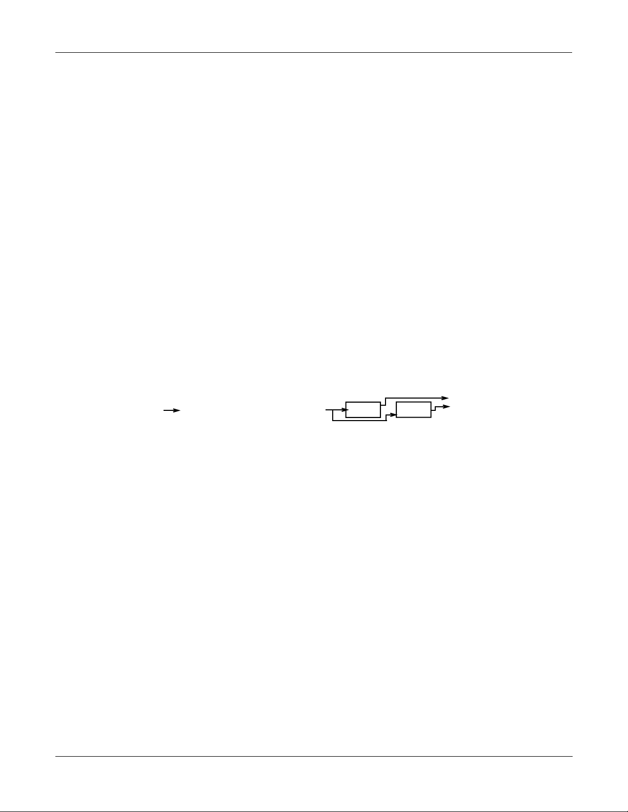
KDFX puts the power of an entire studioÑequalizers, signal processors, and mixersÑinside
your Kurzweil K2500. It allows you to deÞne processing functions, signal paths, and balances,
on sounds created by the K2500 and, in Live Mode, sounds from any source. Using FX
Modulation routings, you have real-time control over any aspects of your studio, from the
buttons, sliders, wheels, and pedals on your K2500, or from any MIDI source at all, like a
sequencer or a dedicated controller.
KDFX provides up to Þve individual signal effects processors. Four of these are designed to
operate on their own individual buses, and the Þfth, the ÒAuxiliaryÓ processor, is designed to
be global.
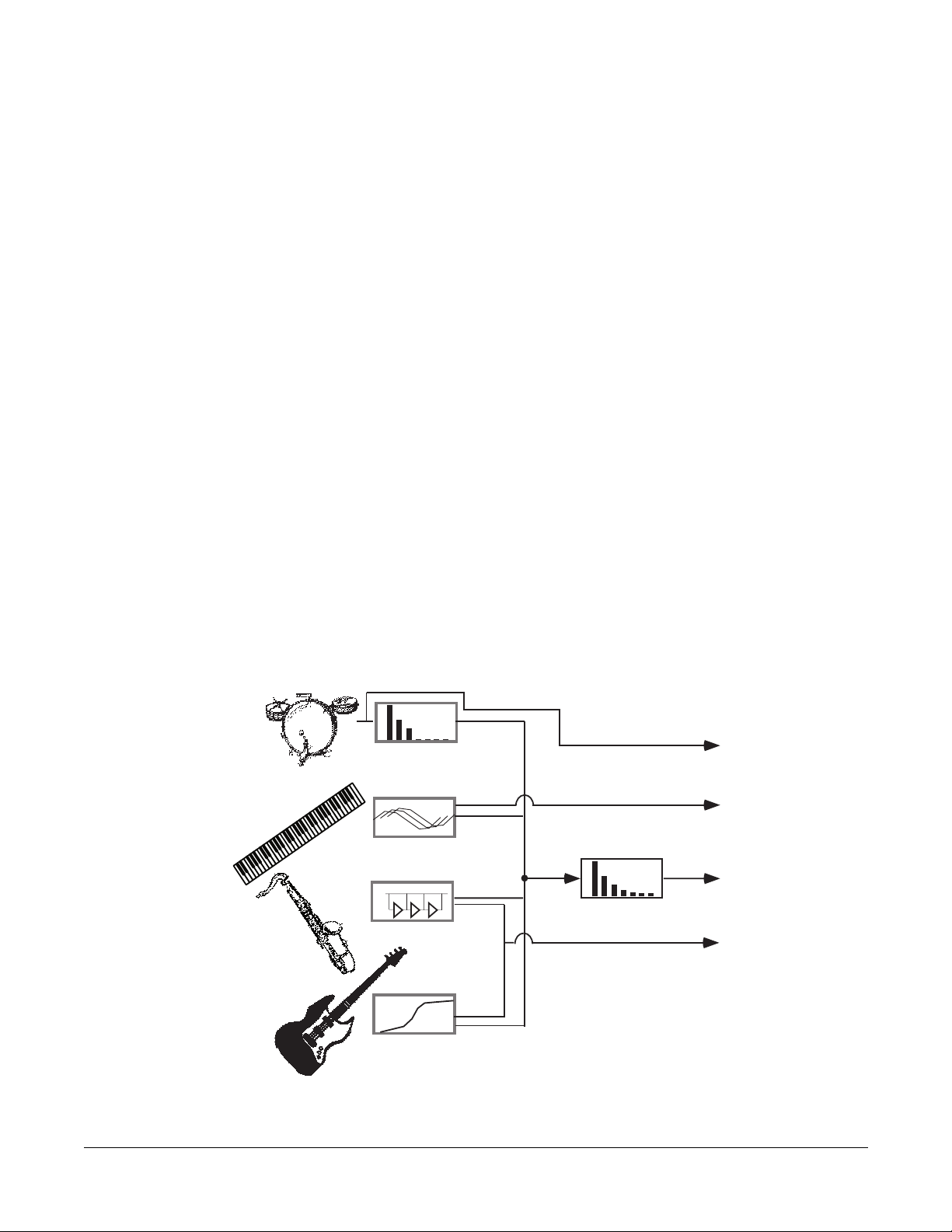
When the K2500 is being used multi-timbrally, KDFX can provide separate processors for each
of several instruments. For example, letÕs say four K2500 channels are in use, under the control
of a sequencer. Each instrument on each channel can have its own processing: ßanger for the
piano, delay for the sax, compression for the bass, and tight reverb for the drums. Then all of
these signals would go through the global Auxiliary (ÒAuxÓ) processor, where they would be
given a room reverb. At the outputs of the K2500, the reverb would show up on one pair, while
the other instrumentsÕ dry or processed (pre-reverb) signals would show up at the others,
either in mono or stereo. Or the entire mix, carefully balanced and panned, could appear at a
single pair, ready to be recorded or played through a PA.
Figure 1-1. A KDFX Studio
1-1
Page 10

What is KDFX
KDFX Terms
Alternatively, in a live performance setting, you can use the KDFX in Setup mode as an entire
orchestra, with different instruments layered on top of each other and mapped to different
parts of the keyboard, all with their own signal processing; and that signal processing can
change completely in an instant when you call up a new Setup.
These are just two of the huge variety of scenarios possible with KDFX. The structure of KDFX
is so ßexible that you should never run out of ideas for how it can be used.
KDFX Terms
Before starting to work with KDFX, it would be good to go over some important terminology
that you will be confronting. Understanding the words will help you get the concepts quickly.
Read this chapter Þrst, and refer to it later if something isnÕt clear.
Studio
A Studio is the entire KDFX environment, consisting of Inputs , FX Bus es, an Aux FX Bus , FX
Presets , Parameter settings, Override s, and Outputs . One Studio is current at a time in KDFX.
Studios are objects, like K2500 programs, and have a number. They can be linked to Programs
or Setups using the FXMode setting . KDFX comes with a large number of useful Studios, and
users can modify them or create new ones and store them in RAM.
FX Bus (also called ÒInsert FX BusÓ)
A signal path with some kind of processing Ña delay, reverb, ßanger, etc.Ñon it. It has stereo
inputs and outputs, and contains an FX Preset which determines the kind of processing that
will be applied. A Studio has four insert FX Buses, each with its own FX Preset, as well as a Þfth
FX Bus, known as the Aux FX Bus .
Aux FX Bus (or just ÒAux BusÓ)
A separate FX Bus from the Insert FX Bus es, which is placed in the signal path after the output
of the Insert FX Buses, so that it can act as a ÒglobalÓ processor.
Mix Bus
The various outputs of a Studio can appear individually at the K2500Õs physical outputs, or two
or more of them can be combined before they get to the physical outputs. The Mix Bus is where
this combining takes place.
FX Preset
An FX Preset determines the type of signal processing that is present on an Insert FX Bus or the
Aux FX Bus . FX Presets consist of an Algorithm , plus the settings of the Parameters associated
with that Algorithm. More than one FX Preset can use the same Algorithm. KDFX comes with a
large number of FX Presets, and users can modify them or create new ones and store them in
RAM. Algorithms, however, are stored in ROM and are not changeable by the user. Each FX
Bus and the Aux FX Bus gets its own FX Preset, so up to Þve FX Presets can be active in a studio
at a time.
1-2
Page 11

FX Algorithm (or just ÒAlgorithmÓ)
A speciÞc type of signal processing, like a hall reverb, plate reverb, chorus, ßanger, pitcher,
compressor, rotary speaker, etc., which is at the core of an FX Preset . KDFX comes with a large
variety of Algorithms, which are stored in ROM, and are not changeable by the user. Additional
Algorithms, supplied by Kurzweil, can be loaded in from disk when they become available.
Algorithm Parameters (RT
those user-controlled parameters are stored in RAM as part of an FX Preset. (DonÕt confuse
these with the VAST Algorithms used inside the K2500 Program Editor.)
, delay feedback, pitch change, etc.) are changeable by the user, and
60
Size/PAUs
How big an Algorithm is, in terms of how much processing power it needs to operate. Size is
measured in Processor Allocation Units, or ÒPAUsÓ. Some simple algorithms require only 1
PAU, while more complex ones require 2, 3, or even 4. The total number of PAUs available to
the four
FX Buses, or manually by the user. The Aux FX Bus has its own set of 3 PAUs, which are not
shared with the Insert FX Buses.
Insert FX Bus es is 4. PAUs can be allocated automatically as FX Presets are assigned to
Parameters
What is KDFX
KDFX Terms
Refers to the user-controlled settings for the different characteristics of an Algorithm . For
example, the user can set the reverb time (RT
delay line to 90%, or the dynamic ratio of a compressor to 10:1. Parameters are stored, along
with the Algorithm they modify, as part of an FX Preset . In certain cases, the parameter settings
within a Studio can be overridden, either using FXMods or Bus Overrides .
FXMods
FXMods allow the Parameters within a Studio to be controlled in real time from outside the
Studio. Almost any parameter within a Studio can be controlled by MIDI commands, such as
sliders or ribbons or sequencer data, or by internal K2500 functions, such as LFOs, envelopes,
clocks, or key states, by setting up an FXMod between the parameter and the desired control
source. FXMods are not set up in the Studio, but rather in a K2500 Program or Setup that will be
associated with that Studio. These links are created on seven ÒFXÓ editing pages in the K2500Õs
Program or Setup editor. A Program or Setup can contain up to 18 FXMods. In addition,
Programs and Setups now contain two dedicated LFOs, two ASR envelopes, and four
FUNctions just for this purpose. FXMods are stored as part of a Program or Setup, not as part of
a Studio or FX Preset.
Bus Overrides (or BusMods)
Bus Overrides allow Parameters within an FX Preset to be controlled on the FX Bus page in the
Studio Editor, outside the FX Preset editor , but still within the Studio. Any two parameters in
an FX Preset can be brought out to its FXBus page. Bus Overrides are stored as part of the
Studio, not as part of the FX Preset. They are useful when an existing FX Preset is close to what
you want, so that you can tweak it without having to create a new FX Preset. Bus Overrides and
FXMods can both exist in a Studio at the same time.
) of an Algorithm to 3.5s, or the feedback of a
60
1-3
Page 12

What is KDFX
KDFX Terms
FXMode setting
Studio Editor
This parameter, which is found on the K2500Õs ÒEffectsÓ Mode page, determines whether the
parameters in a KDFX Studio will be controlled internally or externallyÑin other words,
whether FX Mods will be active. If it is set to ÒProgramÓ, ÒSetupÓ, or ÒAutoÓ, then as you
change the Program or Setup, a different KDFX Studio will load, and any FXMod links between
that Program or Setup and the Studio will be active. If it is set to ÒMasterÓ, then the KDFX
Studio must be chosen manually, and will not change when the Program or Setup changes, and
FXMods in the current Program or Setup will be not be active.
The Studio Editor section is accessed in one of two ways, depending on the FX Mode setting. If
FX Mode is ÒMasterÓ, then the Studio Editor is accessed from the ÒEffectsÓ mode page, by
highlighting the current Studio, and pressing ÒEditÓ. If FX Mode is ÒProgramÓ or ÒSetupÓ, then
the Studio Editor is accessed from within the Program or Setup Editor, by going to the Editor Õs
KDFX page, highlighting the current Studio, and pressing ÒEditÓ.
The Studio Editor consists of the following pages:
Input, where signals coming from the K2500Õs four stereo output buses are routed to one or
more FX Buses in KDFX.
FX Bus, where FX Presets are assigned to the four FX Buses and Bus Overrides are set up.
Aux FX, where an FX Preset is assigned to the Aux FX Bus and Bus Overrides are set up.
FXPreset Editor, which is accessed from the FX Bus page and the Aux FX page by highlighting
the name of the FX Preset and pressing ÒEditÓ. This is where Algorithms are chosen and
Parameters are set for the FX Presets, and where FX Presets are selected, named, and saved.
Output, where the signals coming from the FX Buses and Aux FX are routed to the K2500Õs
eight physical outputs (analog and digital).
Name, Save, Delete, and Dump, for Þle management of KDFX Studios.
Dependent objects
In KDFX, as in K2500 programs, dependent objects are those software objects which make up
part of larger objects: in a Studio, the dependent objects are its FX Presets. The Studio itself is
now a dependent object in Programs and Setups.
Internal Effects
The original K2500 effects processor chip is still usable in a KDFX-equipped unit, and functions
essentially the same as it always has, quite independently from KDFX (except that the FXMode
Setting applies both to it and to KDFX). When we refer to Internal Effects in this manual, weÕre
talking about that one-in, two-out effects processor.
1-4
Page 13

The Structure of KDFX
The Studio
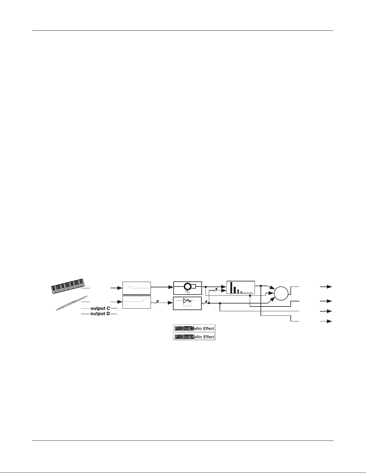
All of KDFXÕs functions are contained in a Studio. Only one Studio is active at a time.
Up to four stereo or eight mono inputs feed a Studio. The sources for these inputs are the four
output pairs available on the Output pages in the K2500Õs Program and Setup Editors: A, B, C,
and D, which are now called ÒKDFX-AÓ through ÒKDFX-DÓ. Instead of going directly to the
K2500Õs physical outputs, these program outputs now feed KDFX, and only after going
through KDFX do they appear at the physical outputs.
The inputs to the Studio can come from one multi-layered program, or from several programs,
or from the K2500Õs own Sample input when the instrument is in Live Mode.
The input signals pass through an input routing systemÑthe Input Editor. Here, the signals go
through individual two-band equalizers, or EQs. Then each input, mono or stereo, is routed to
any two of the four FX Buses.
Each of the FX Buses contains its own signal-processing program, called an FX Preset. Each FX
Preset has a set of parameters: for example the RT60 value on a reverb, or the Feedback level on
a delay line. These parameters can be Þxed as part of the FX Preset, or they can be externally
controlled, from one of two different places. The four FX Buses are also called ÒInsert FX
BusesÓ, because in a conventional studio, thatÕs where they would be found: in the insert loop
of a mixer, between the channel input and the mix bus.
What is KDFX
The Structure of KDFX
There is a Þfth FX Preset, which is located on the Auxiliary FX Bus. The Aux FX Bus follows the
four main FX Presets in the signal path, and is normally conÞgured as a ÒglobalÓ processor.
Each FX Preset is based on an FX Algorithm. An Algorithm is a processing function, like a
reverb, ßanger, or compressor; or a combination of processing functions in a particular order,
like a ßanger followed by a delay followed by a reverb. The Algorithms themselves are Þxed in
ROM, like Kurzweil ROM samples, but the values of their operating parameters can be
changed.
☛The selection of an Algorithm + its user-controlled parameters = an FX Preset.
Each Algorithm requires a certain amount of processing power, which is expressed in
ÒProcessing Allocation UnitsÓ (or PAUs). Simple Algorithms will require 1 PAU, while more
complex Algorithms will require up to 4 PAUs. The amount of processing power available in
each FX Preset is set by its Allocation parameter. When you are selecting an FX Preset for an
insert bus, the number of PAUs its Algorithm requires appears on the display, so you can keep
track of how many PAUs are in use.
PAUs are shared among the four Insert FX buses. There is a limit to the total number of PAUs
that the insert buses can use, and that limit is 4. PAUs can be manually pre-assigned to speciÞc
FX Buses, or using ÒAutoÓ mode they can be assigned automatically as FX Presets are assigned
to the buses. The Auxiliary FX Bus has a separate set of PAUsÑ3 of themÑwhich are not shared
with the insert buses.
Finally, the outputs of the FX Presets are sent to an output routing systemÑthe Output
EditorÑwhere they are then sent to the physical outputs of the K2500.
☛EQs + Input Editor settings + FX Presets + Output Editor settings = a Studio
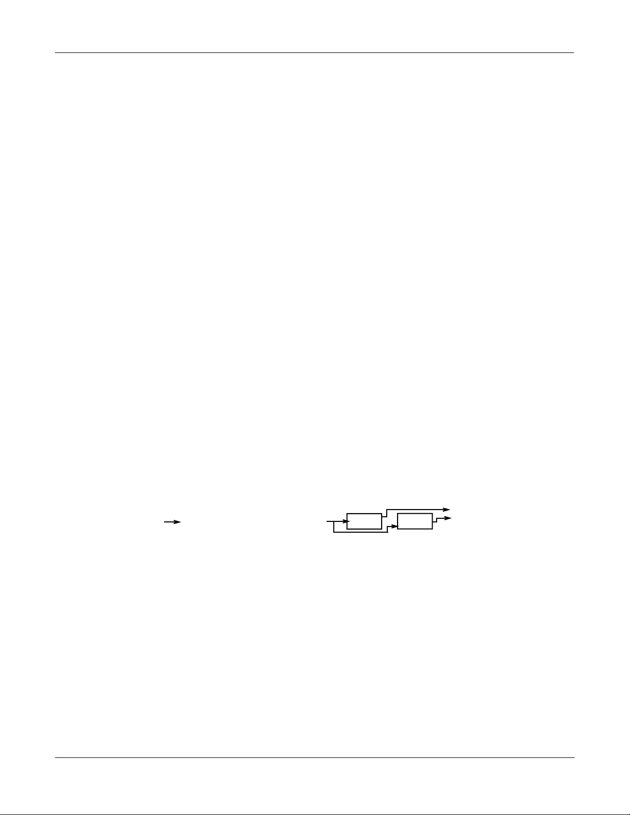
On the following page is a schematic overview of a StudioÕs structure.
1-5
Page 14
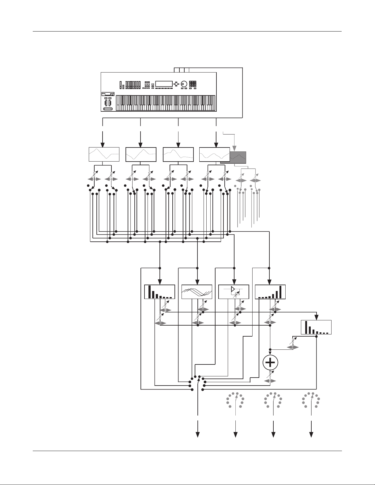
What is KDFX
output A output B output C output D
EQs
FX Presets
program
outputs
physical
outputs
output A output B output C output D
Aux
effect
Mixer
Pre FXBus1
FXBus1
Pre FXBus2
FXBus2
Pre FXBus3
FXBus3
Pre FXBus4
FXBus4
Mix
Aux
Level
Balance/Pan/
Width
If input is mono, each
channel has its own
eqs and sends
All signal paths are
stereo unless noted
Level
Balance
FX1
FX2
FX3
FX4
The Structure of KDFX
1-6
Figure 1-2. KDFX structure
Page 15

Normal Studio Structure
Many of the Studios provided in ROM follow an overall organizational plan, which uses
KDFXÕs resources efÞciently and clearly. While by no means are you required to follow this
structure when creating your own studios, you might want to get familiar with it, and see how
KurzweilÕs own engineers have approached the issue of organization for the Studios in ROM.
¥ Inside the ROM Programs and Setups, each of the outputs KDFX-A through KDFX-D are
assigned based on the type of effects processing that would most likely be appropriate for
the sound on that layer or Program.
¥ Input A/FXBus 1 contains a relatively simple reverb with a low Size requirement.
¥ Input B/FXBus 2 contains an effect which does not increase the ÒlengthÓ of the sound (i.e.,
not reverb or delay), which could include chorus, ßange, distortion, pitcher, EQ, etc.
¥ Input C/FXBus 3 contains effects which take up lots of time, such as delays, and delays
with reverb.
¥ Input D/FXBus 4 is dry.
¥ The AUXFX Bus contains a larger reverb (Size:3), a compressor, or a graphic EQ.
Software Organization
What is KDFX
Controlling KDFX
Like K2500 Programs, the software user interface of a Studio is organized in a Òtop-downÓ
fashion: A Studio is an ÒObjectÓ in K2500 terms, and the FX Presets within a Studio are also
Objects, ÒdependentÓ to the Studio, the way a Keymap is to a Program. Studios and FX Presets
that are modiÞed or created by the user are stored in Program RAM. A Studio contains up to
Þve FX Presets. The same way that one Keymap can be used in multiple Programs, a particular
FX Preset can be used in multiple Studios.
Like ROM Samples in the K2500, KDFX Algorithms are stored in ROM and are unchangeable.
Each FX Preset contains one algorithm. Just as you can use the same Sample in more than one
Keymap, you can use the same algorithm in as many FX Presets as you like. Although you
cannot modify Algorithms, additional KDFX Algorithms will be available from Kurzweil on
disk, which can be loaded into KDFX.
To get inside a Studio, you use the Edit button to reveal the input/EQ, FX Presets, and output
pages. To get inside an FX Preset, use the Edit button to access the Algorithm that the FX Preset
uses, and its associated parameters.
To leave the FX Preset editor, press Exit. If you have made any changes, you will be prompted
to Save the new FX Preset. Then to go back to the StudioÕs main page, press Exit again. If you
have made any changes in the other parameters in the Studio, or in the name or number of the
FX Preset, you will be prompted to Save the new Studio.
Controlling KDFX
Studios can be called up from the K2500 front panel or, like the original K2500 Internal Effects,
they can be assigned to speciÞc K2500 Programs or Setups. If you set the FX Mode parameter
on the K2500Õs Effects mode page to ÒProgramÓ, ÒSetupÓ, or ÒAutoÓ, then changing a Program
(if the current channel agrees with the FX Channel) or Setup will select the Studio associated
with the new Program or Setup. Of course, just as you can use the same Effect in multiple
Programs, you can use the same Studio in multiple Programs or Setups. Setting FX Mode to
ÒMasterÓ means that the Studio will not change with the Program or Setup.
Studio parameters are set in the Studio editor. They initially are given Þxed values, but they can
be also be controlled in real-time by a wide range of control of sources, including K2500 onboard wheels, sliders, and ribbons; various internal software functions; and external MIDI
commands like those coming from a sequencer or a dedicated controller.
1-7
Page 16
What is KDFX
Controlling KDFX
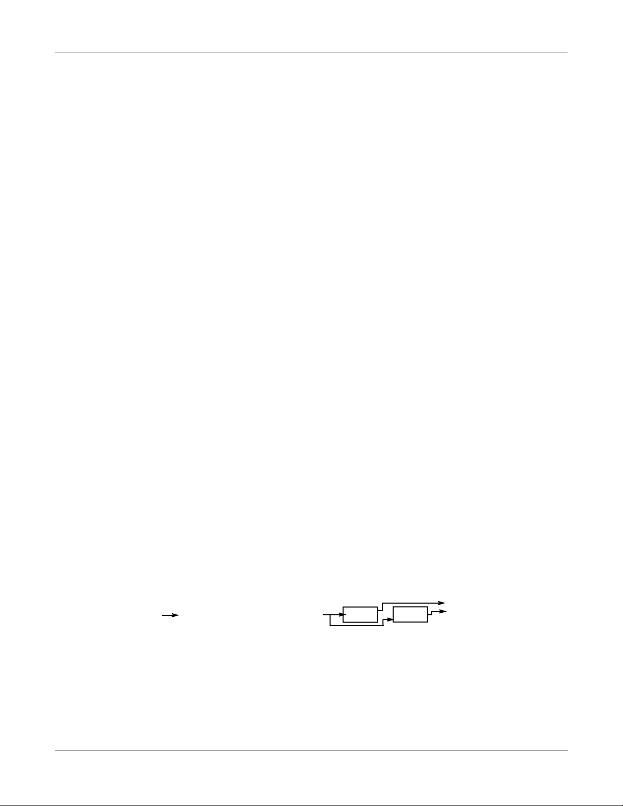
Real-time control of parameters in a Studio is not handled in the Studio editorÑitÕs handled in
a Program or Setup that is associated with a Studio. There are several new pages in Programs
that contain these controls, known as Effects Modulation or FXMod pages. ItÕs here that the
links are set up between real-time control sources and Studio parameters.
In order for these links to work, the FXMode parameter must be set ÒProgramÓ, ÒSetupÓ, or
ÒAutoÓ.
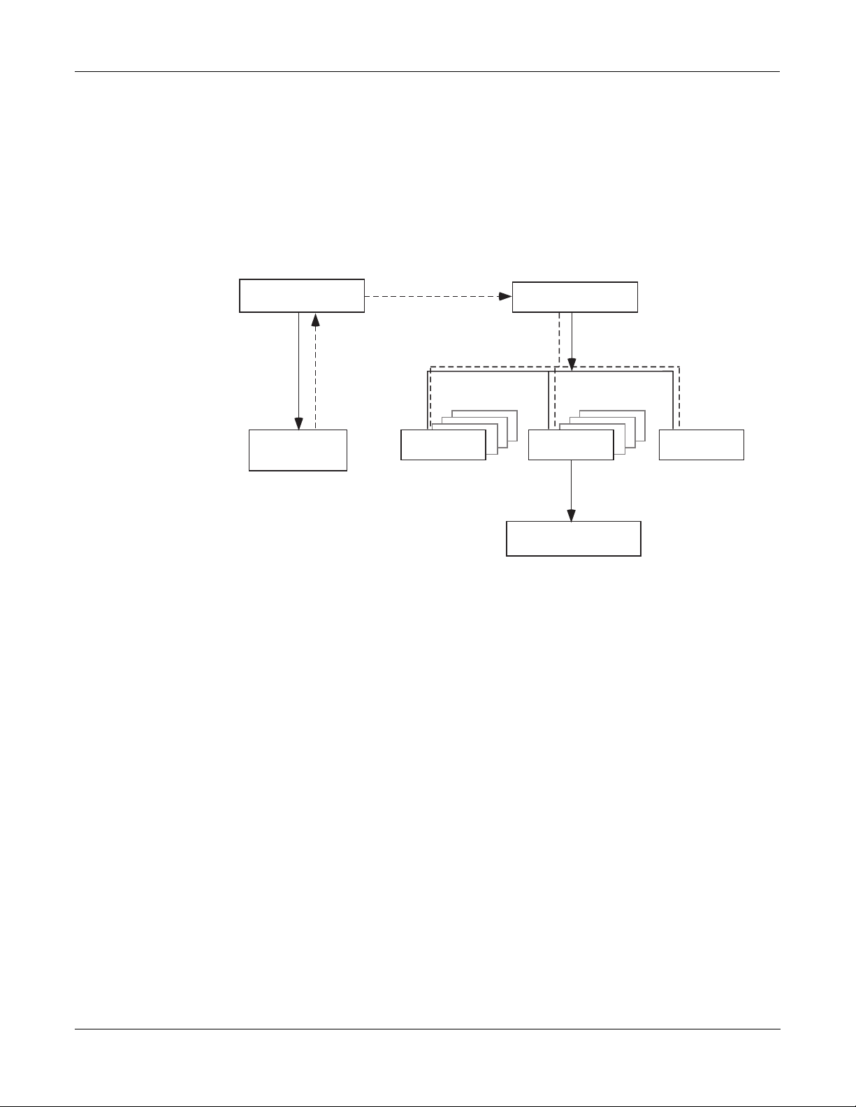
Program or
Setup #
KDFX and
FXMod pages
Figure 1-3. KDFX Software organization
real-time
control
Input mixer
Studio #
FX Preset # Output mixer
algorithm # (in ROM)
parameters
Controlling KDFX with a Sequencer
A useful technique for sequencer users is to set up the Program controlling the Studio
parameters to be an ÒemptyÓ program with no Keymaps but with all of the FX Mods you need
in placeÑthis program produces no sound by itself, and exists only to control the Studio. That
way you can use a dedicated MIDI channel for Studio control. More on this in Chapter 4.
1-8
Page 17

Chapter 2
A Tour of KDFX
LetÕs take a tour through several KDFX Studios. After you do this, you should have a pretty
good idea of what itÕs like to work with KDFX. You will still, of course, have many questionsÑ
answering them is the job of the rest of this manual.
Load the Tutorial Þles
From the KDFX Objects disk that came with your K2500 or KDFX upgrade, load the Þle
ÒTUTOR1B.K25Ó into bank 200...299. You can use a different bank if you like, but then your
numbers and the ones in this chapter will be different.
¥ Insert the disk into the drive
¥ Press Disk to go into Disk mode
¥ Set Current Disk to ÒFloppyÓ
¥ Press Load
¥ Cursor down to ÒTUTOR1B.K25Ó
¥ Press OK
¥ On the ÒLoad this Þle as:Ó screen, select 200...299
¥ Press OK
¥ Press OverWrt (or if you have just installed KDFX or done a Hard Reset, press Append).
¥ Press Exit to get back to Program Mode.
A Simple Studio
Call up Program #199 on your K2500. In Program mode, either scroll the Alpha wheel to
Program 199 (ÒDefault ProgramÓ), or press 1-9-9-Enter on the Alphanumeric pad.
Now go into Effects Mode by pressing the Effects button, and youÕll see this screen:
EffectsMode|||Xpose:0ST|||||<>Channel:1|
FX|Mode:Master
FX|Chan:None
Studio|:199 Default Studio||
Effect|:1|Sweet Hall
Wet/Dry:0%Wet
Dither|:Flat||||||||DigOut|:16|Bit
Octav-|Octav+|Panic|||||||||Chan-||Chan+
If the screen looks very different from this, then put the cursor on the FX Mode parameter and
scroll the Alpha wheel until it says ÒMasterÓ.
Now use the down-arrow button to highlight the Studio parameter. Scroll the Alpha wheel
until it says Ò200 SimpleÓ.
2-1
Page 18
A Tour of KDFX
EditStudio:FXBUS|Size:1|Free:3|<>FXBus:1
FX1||200*4|Tap|BPM|||||||||Aux ||Mix
Wet/Dry |:35%wet|||Lvl:3.5dB|Lvl:-4.5d
Tempo|||||:120BPM|||Bal:0%||||Bal:0%
Allocation:Auto
<more||INPUT||FXBUS||AUXFX||OUTPUT|more>
A Simple Studio
FXBus Editor
Now press EDIT, and this page appears:
This is the FXBus editor for FXBus1. It is where an FX Preset is assigned to the FXBus. Put the
cursor on the box containing Ò200*4 Tap BPMÓÑthis is the current FX Preset, a four-tap delay
whose speed is expressed in terms of tempo (Beats Per Minute). Use the Alpha wheel to scroll
through the many other FX Presets that come with KDFX. Like all K2500 objects, those that are
in RAM (like this one) will have an asterisk in their name, and those that are in ROM will not.
There are three more FX Buses, which can be accessed by pressing the Chan/Bank buttons. In
this studio they are all empty (ÒNo EffectÓ).
Go back to Ò4 Tap BPMÓ on FXBus 1, and play the piano sound from your keyboard. The arrow
next to ÒFX1Ó ßashes, showing that there is audio passing through this FXBus. The arrow keeps
ßashing as long as the FX Bus is processing audio.
Below the FX Preset selector is a Wet/Dry control, which determines how much of the signal
will pass through the FX Preset. Below that is a Tempo control, which sets the timing of the
delays. These parameters are called ÒBus OverridesÓ, because they override parameters which
are actually inside the FX Preset itselfÑthese parameters can be adjusted from inside the FX
Preset, or they can be set from out here, where they are much more convenient. If you change
FX Presets, these values may change, because the particular Overrides and their values will be
different inside the various FX Presets. More about Bus Overrides a little later, and in Chapter 3.
Returns
To the right are two sets of ÒreturnÓ controls from the FX Preset to the output mixer. The Þrst
set, Lvl and Bal, determines how much of the sound will go to the global or Auxiliary Effects
bus, and how its two channels are balanced. On this FXBus, the signal to the Aux bus is boosted
3.5 dB. The second set determines how much of the sound goes to the Mix bus. On this FXBus,
the Mix signal is attenuated -4.5 dB.
Allocation
The Allocation parameter determines how many processor allocation units (PAUs) are
reserved for this FXBus. The number of PAUs an FX Preset uses is dependent on the Algorithm
at the core of the FX Preset. Algorithms can use anywhere from 1 to 4 PAUs, depending on their
complexity. As you scroll through the FX Presets, the number of PAUs required by each one is
shown on the top line of the display (ÒSize:Ó), along with the number of PAUs that are available
(ÒFree:Ó) for other algorithms.
2-2
Page 19
The four Insert FX Buses have 4 PAUs to share among them, so if any bus uses more than one
EditStudio:INPUT||||||||||||<>Input:||A|
||A||LoShelf||HiShelf||FXBus1||None
|||G:0.0dB||G:6.0dB||Lvl:-6.0d
|||F:123Hz||F:1568Hz|Pan:0%
|||||||||||||||||||||Wid:100%
<more||INPUT||FXBUS||AUXFX||OUTPUT|more>
SP
PAU, it means that some buses cannot be assigned an FX Preset. This is a very common
situation, as you shall see. The Auxiliary FX Bus has its own set of 3 PAUs, which are
completely independent and not shared with the insert FX Bus PAUs.
You can Òpre-assignÓ a PAU value to an FX Bus, in which case any FX Presets that require more
PAUs than you have given the bus cannot be loaded into the bus. If you try to put an FX Preset
into a bus that requires more PAUs than are currently available on that bus, the PresetÕs name
appears in parenthesesÑthe same way a K2500 multi-layer drum program is displayed if you
try to access it on a non-drum channel.
Most often, the Allocation parameter will be set to ÒAutoÓ, in which case PAUs are assigned
dynamically as you assign FX Presets to the various buses. As you de-assign FX Presets to
buses, or assign FX Presets with smaller PAU requirements, the PAUs freed up are
automatically re-assigned to other buses where they are needed.
Input Editor
Press the soft button labelled INPUT. This page appears:
A Tour of KDFX
A Simple Studio
This is the input editor. It is showing input A, as indicated both on the left side and in the
upper right cornerÑuse the Chan/Bank buttons to view the other three inputs. Input A is the
ÒKDFX-AÓ stereo signal pair coming from the output of the K2500 Program Editor. In this case,
itÕs our piano program.
The ÒSÓ at the upper left says that the A input is being handled as a stereo feed; this can be
changed to two mono feeds. The ÒPÓ means that the stereo feed has a Pan control; you can
choose to make this a Balance control instead, by setting this parameter to ÒSBÓ
If you play on the keyboard, you can see the arrow next to the letter ÒAÓ ßashing, as audio is
being passed through this part of the Studio. The arrow on this page ßashes only as long as
there is an input signal present.
2-3
Page 20
A Tour of KDFX
A Simple Studio
Equalization
The Þrst two blocks are the low and high EQs on the input. Put the cursor on either block and
turn the Alpha wheel, and you will see the options you have available for types of EQÑthese
include ÒNoneÓ, which bypasses that EQ. The Þrst block has more choices than the second.
The ÒGÓ underneath each block is its Gain: Ó0.0dBÓ is unity gain; the signal passes through
without change. (There is no Gain parameter when a block is set to LoPass or HiPass.) ÒFÓ is the
equalizerÕs frequency. In this Input section, the frequencies above 1568 Hz are boosted 6.0 dB.
Sends
The third and fourth blocks determine the destinations of the Input A signal: each block can be
set to route the signal to any of the four Insert FX Buses, or to ÒNoneÓ. You cannot, however, set
both blocks to the same destination.
The ÒLvlÓ control is the FXBus ÒsendÓ: it sets the level of the signal to the FXBus above it. In this
Input section, the level is backed off 6.0 dB, to compensate for the treble boost in the equalizer,
so that the signal doesnÕt overload the FXBus.
Pan determines the position of the signal respective to the left and right sides. Width (which is
not shown when you are using mono inputs) determines how much the left and right sidesÕ
signals will be separated or blended.
Auxiliary FXBus Editor
Press the AUXFX soft button below the LCD screen. This screen appears:
EditStudio:AUXFX|Size:3|Free:0||||||||||
|Aux||204*Big|Chamber|||||||||||Mix
Wet/Dry|||:58%wet||||||||||||Lvl:0.0dB
Out|Gain||:0.0dB|||||||||||||Bal:0%
<more||INPUT||FXBUS||AUXFX||OUTPUT|more>
This is the global AuxFX editor, and shows us what is happening on the Auxiliary Effects bus.
The AuxFX Bus is a second processor, which follows the four insert FXBuses. It has its own FX
Preset, with Bus Overrides, and level and balance controls to feed it into the Mix bus. Its PAU
allocation is Þxed at 3, so it doesnÕt need an Allocation parameter. It can also be routed all by
itself to an output, as we shall see. In this Studio, the Aux FX bus contains a chamber reverb.
2-4
Page 21
Output Editor
Press the OUTPUT soft button.
EditStudio:OUTPUT||||||||||||||||||||||||
Mix|Lvl:0.0dB||||||Output|A:Mix
Mix|Bal:0%|||||||||Output|B:FXBus1
|||||||||||||||||||Output|C:Off
|||||||||||||||||||Output|D:Off
<more||INPUT||FXBUS|AUXFX||OUTPUT||more>||
The Output editor page is the interface to the real world. It determines which of the signals
going through the various KDFX buses show up at the K2500Õs four sets of physical outputs: A,
B, C, and D. These four outputs, all stereo, go to the K2500Õs analog outputs and to the KDS
digital bus. In addition, output A also goes to the K2500Õs AES/EBU digital output.
A Tour of KDFX
A Simple Studio
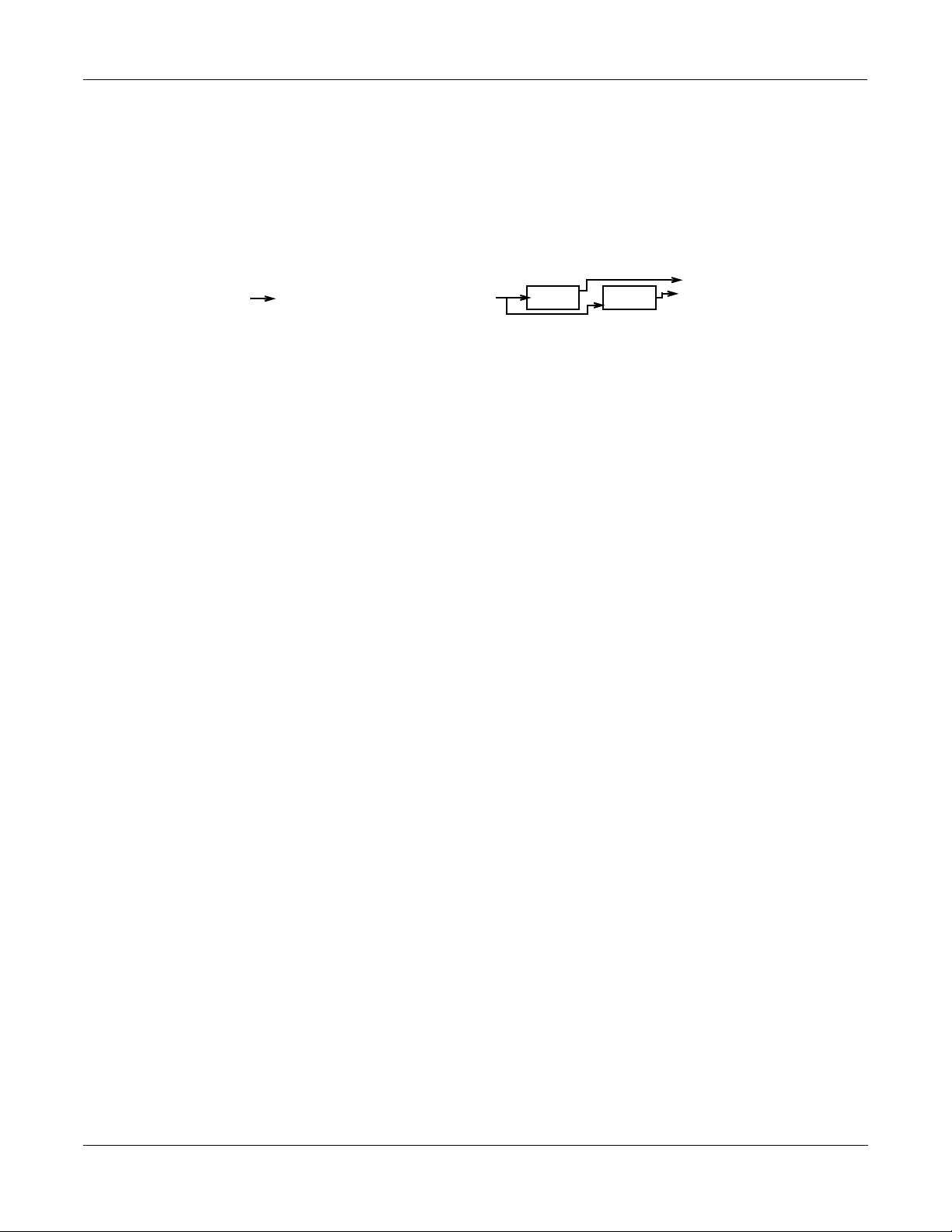
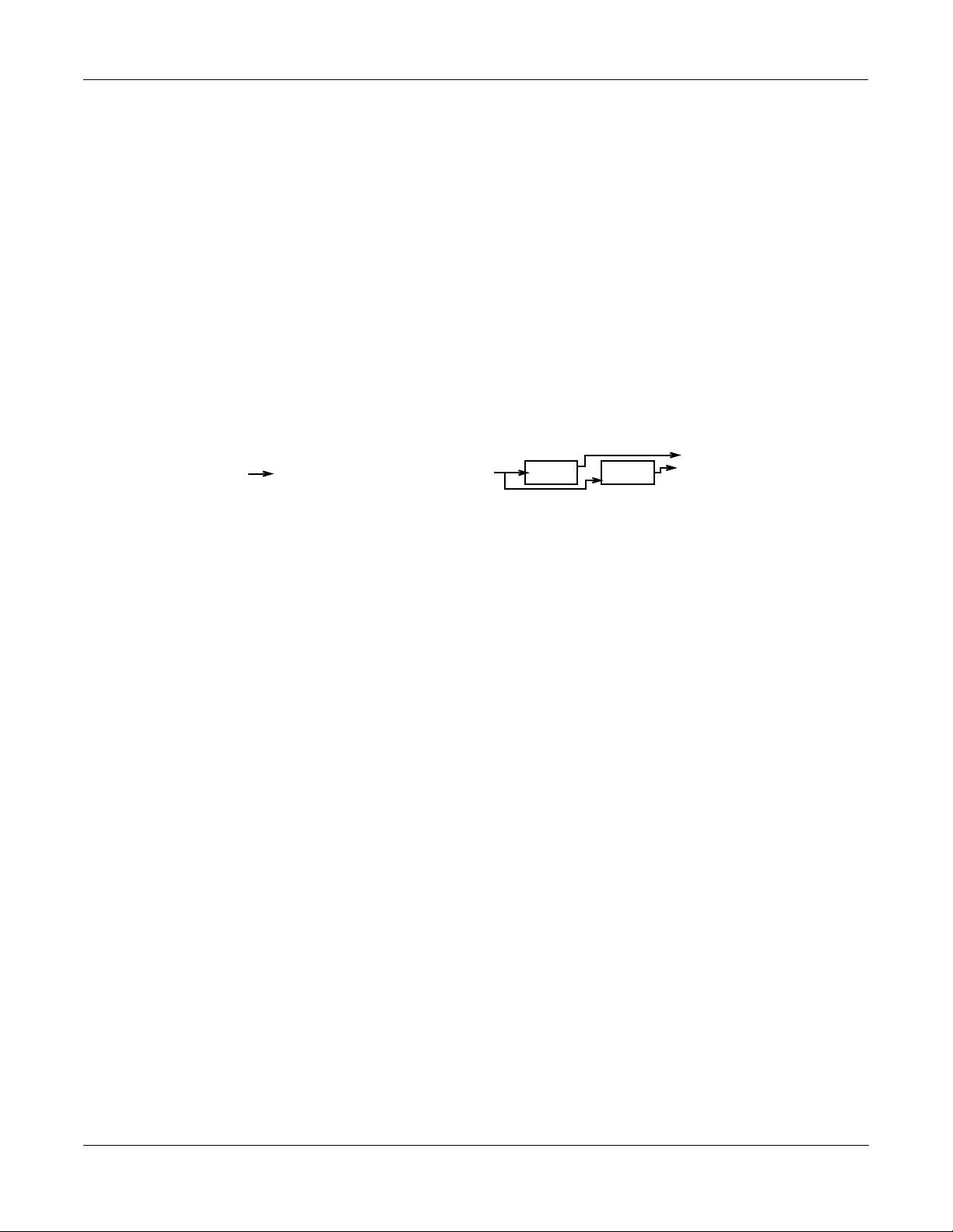
In this Studio, Output A is carrying the Mix Bus, that is, the combination of the outputs of the
four FXBuses (only one of which is in use) and the AuxFX Bus. Output B is carrying FXBus1,
which is the signal after it passes through the delay on FXBus1, but before it gets to the reverb on
the Aux bus. The other outputs are carrying no signal.
HereÕs a diagram of what this Studio looks like:
AuxFXBus
Big Chamber
+3.5dB
-4.5dB
Mix
+
Physical
output A
Output B
Program
output A
-6dB
EQ
Figure 2-1. Structure of Studio 200
FXBus1
4 Tap BPM
2-5
Page 22
A Tour of KDFX
A more complex Studio
A more complex Studio
Press Exit to get to the Effects page, and again to get to Program mode. Call up Program 200,
ElecPno/Flute. This is a split keyboard program: On Layer 1, which has been assigned to the
KDFX-A outputs, is an electric piano, whose key range goes up to B4. On Layer 2, which goes
to the KDFX-B outputs, is a ßute, whose key range starts at C5.
Press Effects and call up Studio 201, RngMd/PFD/Plt. Press Edit to look inside of this Studio.
FX Bus 1
On the Þrst FX Bus is an FX Preset called 201*Tut Ring Mod. The Algorithm this uses is a ring
modulator. This is a processor that takes the sounds coming into it and combines them with
static waveforms by adding and subtracting their frequencies, thereby creating interesting nonharmonic effects. Notice that this FX Preset uses 1 PAU.
EditStudio:FXBUS|Size:1|Free:1|<>FXBus:1
FX1||201*Tut|Ring|Mod||||||Aux ||Mix
Wet/Dry|||:100%wet||Lvl:0.0dB|Lvl:0.0dB
Out|Gain||:0.0dB||||Bal:0%||||Bal:0%
Allocation:Auto
<more||INPUT||FXBUS||AUXFX||OUTPUT|more>
As you play on the lower part of the keyboard, the arrow next to ÒFX1Ó ßashes, but as you play
on the upper part it doesnÕt. ThatÕs because the upper part of the keyboard (the ßute sound) is
routed to a different FXBus.
Bus Overrides
There are two FX Preset parameters on this page: Wet/Dry mix and Output Gain. These
parameters actually exist inside the FX Preset, but are Òbrought outÓ to this page so you can
control them without editing the FX Preset itself. As we saw earlier, these are called ÒBus
OverridesÓ. You can change both the value of the Override parameter and the name of the
parameter that shows up in the Bus Override: to select a different parameter, simply highlight
its name and scroll the Alpha wheel. As you do so, you will see the other parameters inside the
FX Preset which can be brought out to this page.
The two pieces of information that make up each OverrideÑthe name of the parameter being
controlled and its valueÑare stored as part of the Studio, not as part of the FX Preset, and
therefore you donÕt have to create new FX Presets just because you want to change a couple of
parameters. There are two Studio Overrides available for each of the four Insert FX Buses and
two more for the Aux FX Bus.
If you donÕt want any parameter control on this page, then just set the Override to ÒNoneÓ.
The Wet/Dry value is 100%, and the Output Gain is 0.0dBÑunity. The signal on this FXBus
goes both to the Aux bus and the Mix bus at unity gain (0.0 dB).
2-6
Page 23
FX Bus 2
A Tour of KDFX
A more complex Studio
Press the Chan/Bank Up button to get to FX Bus 2.
EditStudio:FXBUS|Size:2|Free:1|<>FXBus:2
FX2||202*Flg+Dly145BPM|||||Aux ||Mix
Wet/Dry|||:90%wet||||Lvl:-9.5d|Lvl:0.0dB
Out|Gain||:-2.5dB||||Bal:0%||||Bal:0%
Allocation:Auto
<more||INPUT||FXBUS||AUXFX||OUTPUT|more>
On this bus is an FX Preset called Flg+Dly145BPM, which uses a combination Algorithm that
has two ßangers, a delay, and a short reverb, all rolled into one. The Ò145BPMÓ part refers to the
fact that the delay times are based on a tempo of 145 BPM,
As you play the ßute sound, the arrow next to ÒFX2Ó ßashes, and it keeps on ßashing as long as
the various feedback delays are sounding. It doesnÕt ßash when you play on the lower part of
the keyboard.
Inputs
This FX Preset uses 2 PAUs. Along with the 1 PAU in use on FXBus 1, this makes 3 of the 4
available PAUs accounted for, so the ÒFreeÓ parameter is 1.
The output conÞguration of this FX Bus has the signal going to the Aux bus attenuated by -9.5
dB, and going to the Mix Bus at unity gain.
The other two FX Buses are empty, which you can conÞrm by pressing the Chan/Bank buttons
a few times: they say Ò199 No EffectÓ.
Now letÕs look at the inputs to the FX Buses. Press the INPUT soft button, and see this page:
EditStudio:INPUT||||||||||||<>Input:||A|
SP
||A||LoShelf||HiShelf||FXBus1||None
|||G:12.0dB|G:0.0dB||Lvl:0.0dB|
|||F:370Hz||F:1047Hz|Pan:0%||||
|||||||||||||||||||||Wid:100%||
<more||INPUT||FXBUS||AUXFX||OUTPUT|more>
Input A carries the electric piano, coming from the ProgramÕs ÒKDFX-AÓ outputs. Play on the
piano part of the keyboard, and the arrow next to ÒAÓ ßashes.
This Input is conÞgured to be stereo. It has a large bass boost: 12.0 dB of everything at 370 Hz
and below, which adds a strong low-frequency emphasis to the signal being ring-modulated.
Its signal is being sent only to the Þrst FX Bus. The stereo separation (Width) of the signal is at
maximum.
2-7
Page 24
A Tour of KDFX
A more complex Studio
Use the Chan/Bank Up button to go to Input B.
EditStudio:INPUT||||||||||||<>Input:||B|
SP
||B||LoShelf||HiShelf||FXBus2||None
|||G:0.0dB||G:4.0dB||Lvl:0.0ddB
|||F:123Hz||F:3136Hz|Pan:0%||||
|||||||||||||||||||||Wid:100%||
<more||INPUT||FXBUS||AUXFX||OUTPUT|more>
This is the ßute, coming from the ProgramÕs ÒKDFX-BÓ outputs. It is also stereo. The incoming
signal has some treble boost on it. It is sent directly to FX Bus 2 at unity gain and full width.
Play on the ßute part of the keyboard, and the arrow next to ÒBÓ ßashes.
The other two Inputs, C and D, are not assigned to any FX Bus.
AuxFX Bus
Now letÕs look at the Auxiliary FX Bus. Press the AUXFX soft button to look at its page.
EditStudio:AUXFX|Size:3|Free:0||||||||||
||Aux||203*MedWarmPlate||||||||||Mix
|||Wet/Dry|||:100%wet|||||||||||Lvl:0.0dB
|||Out|Gain||:0.0dB|||||||||||||Bal:0%
<more||INPUT||FXBUS||AUXFX||OUTPUT|more>
Here is an FX Preset called ÒMedWarmPlate,Ó which is just what it sounds like: a mediumsized, warm-sounding plate reverb. It has two Bus Overrides, Wet/Dry mix, and Output Gain.
The output from the Aux FX Preset is sent to the Mix bus at unity gain.
Since both Insert FXBuses have signal going to the Aux FX Bus, the arrow next to ÒAuxÓ will
ßash as long as any signal processing is going on in either of the Insert FXBusesÑin other
words, when you play anywhere on the keyboard.
2-8
Page 25
Outputs
A Tour of KDFX
A more complex Studio
Finally, press the OUTPUT soft button to get to the Output page. Here we see that the four
physical output pairs all are passing different parts of the studio. If the outputs are connected to
an external mixer, you can treat each of them separately: recording them on different tracks of a
tape deck, sending them to different outboard processors, or mixing them differently in a
monitor mix.
EditStudio:OUTPUT||||||||||||||||||||||||
Mix|Lvl:0.0dB||||||Output|A:Mix
Mix|Bal:0%|||||||||Output|B:FXBus1
|||||||||||||||||||Output|C:FXBus2
|||||||||||||||||||Output|D:AuxFX
<more||INPUT||FXBUS|AUXFX||OUTPUT||more>||
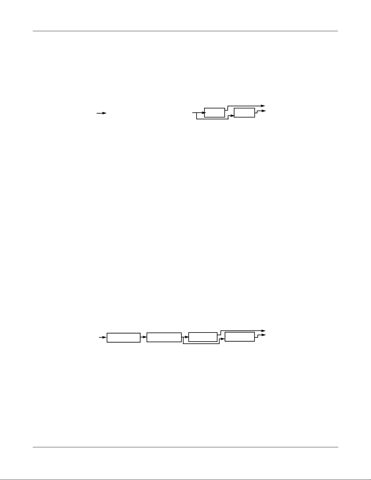
Output A has the Mix bus. This is the combined output of the two FX Buses, plus the reverb on
the AuxFX bus. Its gain and balance (the controls on the left) are at unity.
Output B has the output of FXBus1, that is, the ring-modulated piano, without any reverb.
Output C has the output of FXBus2, the delayed/ßanged ßute, without any reverb.
Output D has the output of the AuxFX bus, which is just the reverb signal, with no dry
component.
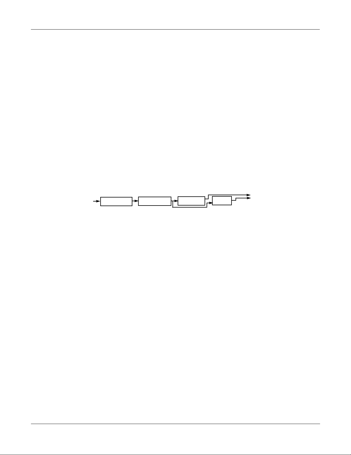
Here is the overall structure for this Studio:
AuxFXBus
MedWarmPlate
-9.5dB
Mix
+
Physical
output A
Output B
Output C
Output D
Program
output A
output B
-5dB
EQs
Figure 2-2. Structure of Studio 201
FXBus1
Tut Ring Mod
FXBus2
Ptc+Flg+Dly145BP
-2.5dB
2-9
Page 26

A Tour of KDFX
A complex Studio with real-time control
A complex Studio with real-time control
The third Studio we will look at is a very complex one, which allows real-time control using
MIDI. Just like the original K2500 Effects, in order to enable MIDI control, the Studio has to be
associated with a particular Program or Setup. The assignments of parameters to be controlled
are made within the Program or Setup, and the Effects mode must be in Program or Setup (or
Auto)
In this example, weÕll work with Setup controlÑthe procedure for working with Program
control is almost exactly the same.
Setting the FX Mode
To enable real-time control from the Setup of KDFX parameters, we have to put the K2500 in
the right Effects mode. Go to the main Effects page, and set FX Mode to ÒSetupÓ. FX Channel
will automatically go to ÒNoneÓ.
EffectMode||||Xpose:0ST|||||<>Channel:1|
FX|Mode:Setup||
FX|Chan:None
Dither|:Medium||||||DigOut||16|Bit
Octav-|Octav+|Panic|||||||||Chan-||Chan+
If you were previously in Master FXMode, youÕll notice that the Studio disappears from the
screen. When FX Mode is set to Setup, you canÕt view the KDFX Studio except from inside the
Setup. This is so you canÕt make any changes in the Studio which the Setup doesnÕt know
about, which could cause all kinds of conßict and confusion.
The Setup
LetÕs look at the Setup that weÕre going to be controlling our Studio with. Press Setup to go into
Setup mode, and select number 200, ÒKDFXComboÓ.
This is a four-Zone Setup, with the keyboard split into three parts: bass and drums at the
bottom, a piano/string pad in the middle, and a breathy-ßutey sound on the top. Each layer
goes to a separate KDFX output, so they can all get different processing.
If you Edit the Setup and look at the various Zones, youÕll see this:
¥ Zone 1: Gtr Jazz Band, a layered bass and drum program, going to KDFX-A
¥ Zone 2: Dual Slap Bass, also going to KDFX-A. This and the previous Zone are active from
¥ Zone 3: Pno & EPno & Pad, a layered piano, electric piano, and string program, going to
¥ Zone 4: Hybrid Vox, going to KDFX-C, and active from G5 and up.
the bottom of the keyboard up to A3.
KDFX-B, which is active from Bb3 to F#5.
2-10
Note: if you are using a K2500R and controlling it from a conventional MIDI keyboard (i.e., not
a PC-88), see ÒA Note about KDFX in SetupsÓ at the end of this chapter before proceeding
further.
Page 27
Looking at the Studio
To view the Studio, press Edit, and more> three times, and then the KDFX soft button. The
name of the Studio associated with this Setup, 202*Complex, will appear.
EditSetup:KDFX||||||||||||||||All|Zones||
Studio:202*Complex||||||||||
Bus:|Param:|||||Adjust:||Source:||Depth:
FX1||In/Out|||||Out||||||SoftPd|||1
FX1||Aux|Lvl||||-55.0dB||MIDI27|||52dB
FX2||L|Fdbk|Lvl|100%|||||MIDI26|||120%
<more||KDFX|||FXMOD2|FXMOD3|FXMOD4|more>
(There is nothing wrong with your manualÑsome of the parameters are in grey deliberately.
Ignore them for now.)
Put the cursor on the StudioÕs name and press Edit, and letÕs dig into this Studio.
Press INPUT if youÕd like to look at the Input pages. These are all set up straightforwardly,
with Input A going to FXBus1, Input B going to FXBus2, etc.
A Tour of KDFX
A complex Studio with real-time control
On the FX Bus pages: FXBus 1
Press FXBUS to look at the FX buses. On FXBus 1 is 205*CompresHK, a hard-knee compressor.
EditStudio:FXBUS|Size:1|Free:0|<>FXBus:1
FX1||205*CompresHK|||||||||Aux ||Mix
In/Out||||:FXMod|||||Lvl:FXMod|Lvl:-5.0dB
None||||||:||||||||||Bal:0%||||Bal:0%
Allocation:Auto
<more||INPUT||FXBUS||AUXFX||OUTPUT|more>
Look at the ÒIn/OutÓ parameter. This is a Bus Override, meaning this parameter is actually
inside the FXPreset but it can be changed from here. However, instead of saying ÒInÓ or ÒOutÓ
it says ÒFXModÓ. This means that this parameter isnÕt controlled from inside the Studio at allÑ
itÕs controlled by something else entirely outside the studio.
As it happens, itÕs controlled by the soft pedal, controller number 67ÑSwitch Pedal 3 for K2500
keyboard users. WeÕll see how this is done in a moment. Pressing this pedal will cause the
compressor to kick in, squashing the dynamic range of the sound. However, the MakeUpGain
inside the compressor is set to 6.5 dB, so the level doesnÕt change much when the compressor is
engaged.
This type of control is useful on this program, because it uses velocity-switching to change
drum and bass sounds. Normally as you play harder, the sounds change, and they also get
louder. With the compressor engaged, however, the drum and bass sounds can change without
getting louder.
ThereÕs another FXMod, which is assigned to the Aux FX Bus send level. On the Aux bus is a
reverb, so this FXMod controls how much of the signal coming through here will get reverbed.
It happens to be under the control of Slider G, controller number 27. Play the bass and drums
and move that slider, and hear the reverb go in and out.
2-11
Page 28
A Tour of KDFX
A complex Studio with real-time control
Setting up FXMods
How are these controls set up? ThatÕs back on the KDFX page in the Setup. Exit the Studio (if
you have made any changes, donÕt save themÑthat will only confuse things!) and look at the
settings here:
EditSetup:KDFX||||||||||||||||All|Zones||
Studio:202*Complex||||||||||
Bus:|Param:|||||Adjust:||Source:||Depth:
FX1||In/Out|||||Out||||||SoftPd|||1
FX1||Aux|Lvl||||-55.0dB||MIDI27|||52dB
FX2||L|Fdbk|Lvl|100%|||||MIDI26|||116%
<more||KDFX|||FXMOD2|FXMOD3|FXMOD4|more>
On FX1 bus, the In/Out parameter has an initial value (ÒAdjustÓ) of ÒOutÓ, which means that
normally it is not engaged.
The controller that controls this parameter is the ÒSourceÓ, and in this case, it is the Soft
Pedal/Switch Pedal 3, MIDI controller 67. The amount the Source can change the parameter is
the Depth, and here it is Ò1Ó.
On a parameter that has only two states, like ÒIn/OutÓ, the Depth can only have three values: 1,
0, or -1. If it is set to 1 or -1, then changing the source puts the parameter into its other stateÑin
this case, going from Out to In. (If itÕs set to 0, then changing the Source has no effect on the
parameterÕs state.)
Also on the FX1 bus, the Aux Lvl is initially -55 dB. The Source, MIDI controller 27, can raise
that level by as much as 52 dB, to put it at -3 dBÑand in fact, thatÕs what youÕre hearing as you
move Slider G.
FX Bus 2
LetÕs go back into the Studio and look at FXBus 2Ñpress Edit and then Chan/Bank Up. HereÕs
our piano and string pad, going through an FX Preset called 206*Fast&RichChorus.
EditStudio:FXBUS|Size:1|Free:1|<>FXBus:2
FX2||206*Fast&RichChorus|||Aux ||Mix
None||||||:|||||||||Lvl:FXMod|Lvl:0.0dB
None||||||:|||||||||Bal:0%||||Bal:0%
Allocation:Auto
<more||INPUT||FXBUS||AUXFX||OUTPUT|more>
The Aux Lvl, as on FXBus1, is also under FX Mod control. If you now go inside the FX Preset
(by pressing Edit), youÕll see that the left and right feedback levels (ÒFdbk LvlÓ) are under
FXMod control.
EditFXPreset:PARAM1|||||||EffectSize:1/1
FXAlgorithm:152|Dual|Chorus|1|
||||||||||||||||||||In|Gain|||:0.0dB
L|Wet/Dry|:50%wet|||R|Wet/Dry|:50%wet
L|Out|Gain:0.0dB||||R|Out|Gain:0.0dB
L|Fdbk|Lvl:FXMod||||L|Fdbk|Lvl:FXMod
Xcouple|||:0%|
<more||PARAM1|PARAM2|PARAM3||||||||more>
2-12
Page 29
A Tour of KDFX
A complex Studio with real-time control
Press PARAM2, youÕll see that the Left and Right LFO1 Rates are also under FXMod control.
EditFXPreset:PARAM2|||Dual|Chorus|1|||||
L|Tap|Lvl|:75%||||||R|Tap|Lvl|:75%|
L|Tap|Pan|:-100%||||R|Tap|Pan|:100%
L|LFO|Rate:FXMod||||R|LFO|Rate:FXMod
L|LFODepth:5.0ct||||R|LFODepth:5.0ct
L|Tap|Dly|:4.0ms||||R|Tap|Dly|:4.0ms
L|HF|Damp|:25088Hz||R|HF|Damp|:25088Hz
<more||PARAM1|PARAM2|PARAM3||||||||more>
Go back out of the FXPreset and the Studio, to the SetupÕs KDFX page. Here we see that on FX
Bus 2, L Fdbk Lvl has a starting value of 0%, and can be changed, using MIDI controller 26
(Slider F), up to 100%.
Press FXMOD2 to go to the next page of FXMods, and youÕll see the same slider changing the R
Fdbk Lvl, only in this case the Depth is -100%, meaning the feedback on this channel will be out
of phase with the main signal.
EditSetup:FXMOD2||||||||||||||All|Zones||
Bus:|Param:|||||Adjust:||Source:||Depth:
FX2||R|Fdbk|Lvl|0%|||||||MIDI26|||-100%
FX2||L|LFO1Rate||0.50Hz||MIDI25|||8.25H
FX2||R|LFO1Rate||0.52Hz||MIDI25|||8.25H
FX2||Aux|Lvl||||-15.5dB||MIDI27|||15dB
FX3||Fdbk|Level|10%||||||MIDI24|||89%
<more||KDFX|||FXMOD2|FXMOD3|FXMOD4|more>
Further down the FXMOD2 page are the assignments to the LFO rates: MIDI controller 25
(Slider E) is assigned to the left and right LFO1 Rates, with minimum values of 0.50 and 0.52
Hz, respectively, and maximum change of 8.25 Hz. Set the feedback level high and you can
really clearly hear the LFO rate changing (but watch out that the effect doesnÕt go into
oscillation at the highest feedback level).
Finally, MIDI Controller 27, our old friend Slider G, controls the Aux Level send on this bus as
,
well, thereby determining how much reverb will appear on the signal on this bus. There are no
limits to how many FXMods a single Source can be assigned to.
FXBus 3
Press Edit, then use the Chan/Bank button to select FXBus 3. HereÕs where our breathy ßute
sound is, and itÕs going through a delay FXPreset called 207*Adj Delay.
EditStudio:FXBUS|Size:1|Free:1|<>FXBus:3
FX3||207*Adj|Delay|||||||||Aux ||Mix
Wet/Dry|||:50%wet|||Lvl:FXMod|Lvl:0.0dB
Out|Gain||:0.0dB||||Bal:0%||||Bal:0%
Allocation:Auto
<more||INPUT||FXBUS||AUXFX||OUTPUT|more>
2-13
Page 30

A Tour of KDFX
A complex Studio with real-time control
Go inside the FXPreset, and youÕll see that the Feedback Level is under FXMod control.
EditFXPreset:PARAM1|||||||EffectSize:1/1
FXAlgorithm:131|4-Tap|Delay|
||||||||||||||||||||In|Gain|||:0.0dB
Wet/Dry|||:50%wet|||Out|Gain||:0.0dB
Fdbk|Level:FXMod
||||||||||||||||||||Dry|Bal|||:0%
HF|Damping:25088Hz||Hold||||||:Off|
<more||PARAM1|PARAM2|PARAM3||||||||more>
Press PARAM2, and on that page, youÕll see that Delay Scale is also under FXMod control.
EditFXPreset:PARAM2|||||4-Tap|Delay|||||
Loop|Crs||:480ms|||||
||||||||||||||||||||DelayScale:FXMod|
Loop|Fine|:0.0ms
Tap1|Crs||:120ms||||Tap3|Crs||:360ms|
Tap1|Fine|:0.0ms||||Tap3|Fine|:10.0ms|
Tap2|Crs||:240ms||||Tap4|Crs||:480ms|
Tap2|Fine|:5.0ms||||Tap4|Fine|:-5.0ms|
<more||PARAM1|PARAM2|PARAM3||||||||more>
Go back out to the Setup, and look at the bottom of the FXMOD2 page. Here we see the
Feedback Level parameter is under the control of Controller 24 (Slider D), with a minimum of
10% and a maximum of 10+89=99%.
EditSetup:FXMOD3||||||||||||||All|Zones||
Bus:|Param:|||||Adjust:||Source:||Depth:
FX3||DelayScale||0.54x|||Foot||||||6.00x
FX3||Aux|Lvl||||-50.0dB||MIDI27|||52dB
None|None||||||||||||||||OFF
None|None||||||||||||||||OFF
None|None||||||||||||||||OFF
<more||KDFX|||FXMOD2|FXMOD3|FXMOD4|more>
On the FXMOD3 page, we see that the Delay Scale, which scales all of the various delays in the
Algorithm, is controlled by the Foot Pedal, MIDI controller 4ÑControl Pedal 1 for K2500
keyboard users. The delay is nominally a 480 ms loop, with four equal-spaced taps inside it, 120
ms apart. With the Foot Pedal, we can scale all those times by a factor of between 0.54 and 6.00.
Finally, the Aux Level from this bus, controlling the reverb send, is once again assigned to MIDI
controller 27, Slider G.
So hereÕs a summary of the FXMods in this studio:
¥ Switch pedal 3 (Soft pedal) puts compression on the bass and drums.
¥ Slider F controls the feedback on the chorus on the piano/string pad. Slider E controls the
LFO speed on that chorus.
¥ Slider D controls the feedback on the delay on the breathy ßute.
¥ Control Pedal 1 (Foot Pedal) controls the delay time on the breathy ßute.
¥ Slider G controls the reverb send for all three Zones.
2-14
Page 31

A Note about KDFX in Setups
As we mentioned earlier, using Setups on a K2500R and a conventional MIDI keyboard
requires some special consideration. In order to play Setups, which normally require a multizoned/multichannel keyboard like the K2500 or PC-88, the K2500R includes a parameter called
ÒLocal Keyboard ChannelÓ (LocalKbdCh), which is found on the MIDI:Receive page. If you
set this parameter to the transmitting channel of the keyboard, then the K2500 takes all
incoming MIDI data on that channel and treats it as if it was coming from a local keyboardÑ
that is, it plays all the Zones in the Setup.
However when you use this feature, be aware that many MIDI controller commands are
ÒremappedÓ by the SetupÕs parameters. See Chapter 4 for more information, and a list of the
MIDI controllers that are remapped.
Building your own
Now that weÕve walked you through a very complex studio, here are some hints on how to go
about building your own.
First, you want to decide whether you want the Studio to be static, or to be dynamic under
KDFX control from the K2500 keyboard and/or an external MIDI source, and/or to change
when the Program or Setup changes. If itÕs to be static, then Effect mode must be set to Master.
If itÕs to change in any way in real time, the Effects mode must be Program, Setup, or Auto,
depending on how you want to approach it.
A Tour of KDFX
Building your own
Then you need to look at how your Program outputs are arranged, so you can design the
Studio intelligently. If youÕre using internal Setups, look at the output assignments on the
various Zones, and change them so that sounds that need different effects are separated, and
those that can use the same effects are grouped. If youÕre using a MIDI sequencer, you might
want to use the ÒOutPairÓ parameter found on the MIDI:Channels page (see page 10-9 in the
K2500 Performance Guide), and arrange your sequence so that the routings of tracks to FX Buses
can be determined by their MIDI channel assignments.
Now set up your Studio, assigning FX Presets to the Program outputs/KDFX inputs. Many of
the ROM Studios follow a common organizational plan, which might be a good starting point
for your Studios:
¥ FXBus 1 contains a relatively simple reverb with a low Size requirement.
¥ FXBus 2 contains an effect which does not increase the ÒlengthÓ of the sound (that is, not
reverb or delay). Possibilities include chorus, ßange, phaser, distortion, shaper, pitcher,
enhancer, EQ, or EQ Morpher.
¥ FXBus 3 contains effects which take up lots of time, such as delays, delays with reverb, or
other ÒLeadÓ sounds.
¥ FXBus 4 is dry, and is used as a ÒbypassÓ bus going directly to the Aux FXBus. (ItÕs also
good to think this way if all of the PAUs have been used by the other Buses.)
¥ The Aux FXBus contains a larger reverb (Size: 2 or3), a compressor, or a graphic EQ. It can
often be used instead of an FXBus reverb, such as the one on FXBus1. If you use it in this
way (set the Aux Lvl on FXBus 1 to 0dB or higher), it frees up FX Bus 1 for use as an
Enhancer, Stereo Image, Flanger, etc.
Finally, set up your KDFX Mods in the Setup or Program you plan to use. If you are using a
sequencer, you might want to dedicate a Program just to KDFX Mods, with no sound coming
from that program.
2-15
Page 32

A Tour of KDFX
Building your own
DonÕt forget to Save your Studio!
Static KDFX Mods
Keep in mind that KDFX Mods donÕt always have to be dynamicÑthey can be used when you
want to just change a few parameters in a Studio. Link the Studio with a Program or Setup. Set
the Adjust values of the parameters you want to change to the new values, and set Source to
OFF. Now save the Program or Setup. This lets you create as many variations on a Studio as
you want, without making each variation a separate Studio. When you want to use the tweaked
Studio, just call up its Program or Setup.
And donÕt forget to have fun. But now, read the rest of the manual.
2-16
Page 33

Chapter 3
FXBus 4
Input D
Input C
Input B
Input A
Chan/Bank
AuxFX
Output
FXBus 3
FXBus 2
FXBus 1
algorithm
param 1
Edit
Edit
Name
Save
Delete Dump
<more>
Name
<more>
param 2
Save Delete Dump
Edit
Name
<more>
param 2
Save Delete Dump
Chan/Bank
(if mono)
Studio
FX Preset (Aux)
FX Preset (1-4)
algorithm
param1
Studio|
Effects Mode
Insert FX
Inside KDFX
This chapter will analyze the organization of KDFX in detail.
Personalities
KDFX can be said to have two distinct Òpersonalities,Ó depending on the setting of the
ÒFXModeÓ parameter on the FX Mode page.
If FXMode is set to ÒMasterÓ, then all KDFX parameters are set within the Studio, and remain
unchanged unless the Studio or any of its FX Presets are edited.
If FX Mode is set to anything else ÑÓProgramÓ, ÒSetupÓ, or ÒAutoÓÑthen one or more
parameters within the studio may be under the control of an outside source, such as MIDI or
one of the K2500Õs control sources, and can be continuously changed in real time without
editing the Studio or any FX Presets.
For the sake of clarity, in this chapter, we will deal with KDFX only in ÒMasterÓ mode. The
issues of real-time control will be dealt with in depth in the next chapter.
☛So for starters, set the FX Mode parameter on the Effects Mode page to ÒMasterÓ and the
Channel parameter to ÒNoneÓ before going further into this chapter.
Navigating KDFX
The largest component in KDFX is the Studio. The Studio encompasses all of KDFXÕs signal
routings, processing algorithms, and processing parameters. When you change any parameter
in a Studio, you are potentially creating a new Studio, just as when you change a parameter in a
Program, the Program is no longer the same. The user interface within a Studio is organized
according to the following diagram:
3-1
Figure 3-1. KDFX user-interface map
Page 34

Inside KDFX
Navigating KDFX
To select a Studio, on the main Effects page move the cursor so the Studio name is highlighted.
EffectMode|||||Xpose:0ST|||||<>Channel:1|
FX|Mode:Master
FX|Chan:None
Studio|:2|RmChorChRv|Hall||
Effect|:1|Sweet Hall
Wet/Dry:0%Wet
Dither|:Medium||||||DigOut|:16|Bit
Octav-|Octav+|Panic|||||||||Chan-||Chan+
FX Bus
When the Studio is highlighted, pressing Edit goes to the Studio Editor (EditStudio) level, and
the FXBus page. There are four FXBus pages, which are selected using the Channel/Bank Up
and Down buttons. If you have just entered the Studio Editor, the Þrst FXBus page you see will
be the FXBus1 page. Once you are inside the Studio Editor, however, when you press the
FXBUS soft button from another page, it will take you to whichever FXBus page you were last
looking at.
EditStudio:FXBUS|Size:1|Free:0|<>FXBus:1
FX1||17|Percussive|Room||||Aux ||Mix
Wet/Dry :33%wet|||Lvl:0ff |Lvl:0.0dB
Out Gain :0.0dB||||Bal:0%||||Bal:0%
Allocation:Auto
<more||INPUT||FXBUS||AUXFX||OUTPUT|more>
The four FXBuses are the equivalent of four effects processors inserted into the effects loop of a
mixing console. Therefore, they are known as the ÒInsert effectsÓ.
Parameters
When you are on an FXBus page, highlighting the name of the FX Preset (or any of the
parameters directly below it) and pressing Edit accesses the Þrst page of Parameters for that FX
Preset. An FX Preset is an object within the Studio, much like a Keymap is an object within a
Program. The same FX Preset can be used in more than one Studio, or more than once in the
same Studio (provided you donÕt run out of PAUs).
The Þrst EditFXPreset Parameter page includes the FX Algorithm that the FX Preset is based
on. Additional pages of Parameters are accessed by soft buttons. Depending on how complex
the Algorithm is, there may be as many as four Parameter pages in an FX Preset. Algorithms are
in the K2500 ROM, and are not normally changeable, deletable, or saveable by the user. Like
ROM samples, they are simply always there. (Additional Algorithms, however, may be loaded
in from disk when they become available from Kurzweil.)
3-2
Page 35

Inside KDFX
EditStudio:INPUT||||||||||||<>Input:||A|
||A||LoShelf||HiShelf||FXBus1||FXBus2
|||G:0.0dB||G:0.0dB||Lvl:0.0dB|Lvl:Off
|||F:123Hz||F:9956Hz|Pan:0%||||Pan:0%
|||||||||||||||||||||Wid:100%||Wid:100%
<more||INPUT||FXBUS||AUXFX||OUTPUT|more>
SP
Navigating KDFX
EditFXPreset:PARAM1||||||||EffectSize:1/1
FXAlgorithm:1|MiniVerb|||||||||||||
||||||||||||||||||||In|Gain|||:0.0dB
Wet/Dry|||:33%wet|||Out|Gain||:0.0dB
Rvrb|Time|:2.0s|||||HF|Damping:4699Hz
L|Pre|Dly|:0ms||||||R|Pre|Dly|:0ms
<more||PARAM1|PARAM2|||||||||||||||more>
Pressing the More soft buttons accesses Name, Save, Delete, and Dump pages for the FX Preset.
Pressing Exit goes back to the FXBus page, and if you have made any changes in the FX Preset
you will be prompted to save it. If you save the FX Preset to the same location, and the same FX
Preset is used on another bus (either in this Studio or another), then any changes you have
made will affect all buses using that FX Preset.
Input
From anywhere inside the Studio Editor, pressing the INPUT soft button brings you to the
Input A page.
The other Input pagesÑB, C, and DÑare selected by using the Chan/Bank Up and Down
buttons. Depending on how the inputs are conÞguredÑstereo or monoÑthere will be from
four to eight Input pages.
Similar to the FX Bus pages, the Þrst time you look at an Input page after entering the Studio
Editor, it will be the Input A page (or, if itÕs mono, the Input A/L page). Once you are in the
Studio Editor, when you press the INPUT soft button from another page, it will take you to
whichever Input page you were last looking at.
Aux FX
Another soft button inside the Studio Editor accesses the AuxFX page. This is a separate effects
bus, which can be used by itself, or in a chain following one or more of the insert Effects.
Like the insert FX buses, you access the FX PresetÕs parameters, including its Algorithm, by
highlighting the FX PresetÕs name and pressing Edit. As on the insert FX Buses, the FX Preset
on the AuxFX bus has up to four pages of parameters, and the More soft buttons access Name,
Save, Delete, and Dump pages for the FX Preset. The same FX Preset can be used in the AuxFX
bus as in any of the insert FX Buses.
3-3
Page 36

Inside KDFX
Navigating KDFX
|||Wet/Dry|||:100%wet|||||||||||Lvl:0.0dB
|||Out|Gain||:0.0dB|||||||||||||Bal:0%
EditStudio:AUXFX|Size:3|Free:0||||||||||
||Aux||69|Short|Hall|||||||||||||Mix
<more||INPUT||FXBUS||AUXFX||OUTPUT|more>
The AuxFX page can also be accessed from any of the FXBus pages by placing the cursor on the
block labelled ÒAuxÓ and pressing Edit.
Pressing Exit goes back to the AuxFX page on the EditStudio level. If you have made any
changes in the FX Preset, you will be prompted to save the FX Preset.
Output
In the Studio Editor, pressing the Output soft button accesses the Output page, where the
KDFX ÒvirtualÓ outputs are assigned to the K2500Õs physical outputs.
EditStudio:OUTPUT|||||||||||||||||||||||
Mix|Lvl:0.0dB||||||Output|A:Mix
Mix|Bal:0%|||||||||Output|B:Off
|||||||||||||||||||Output|C:Off
|||||||||||||||||||Output|D:Off
<more||INPUT||FXBUS|AUXFX||OUTPUT|more>||
The Output page can also be accessed from any of the FXBus pages by placing the cursor on the
block labelled ÒMixÓ and pressing Edit.
Name, Save, Delete, Dump
From any of the EditStudio pages, pressing either of the more soft buttons accesses Name, Save,
Delete, and Dump pages for the Studio. Studios are stored in RAM, like K2500 Programs, and
when a Studio is recalled, all of its associated FX Presets and parameters are recalled with it.
Studios in ROM occupy slots in the 0É99, 100É199, and 700É799 banks. You may override
these if you like, or use the RAM banks (200-699 and 800-999) for your Studios. The ROM
Studios are always there, and if you delete a Studio that youÕve stored in a ROM slot, the
original ROM Studio will pop up in its place.
When you save a Studio, you can also rename it, using the standard naming screen:
EditStudio:Rename|||||||||||||||||||||||
3-4
Studio|Name:||||RmChorChRv|Hall
Delete|Insert||<<<||||>>>||||OK|||Cancel
Page 37

The Compare and FX Bypass Buttons
As with all K2500 objects, the ÒCompareÓ (Disk) button lets you switch back and forth between
the last saved version of whatever you are editing and its current state.
If you are on a page at the EditStudio level, Compare toggles between the last-saved and
current versions of the Studio. If you are inside an FX Preset, on the EditFXPreset level,
Compare toggles between the last-saved and current versions of the FX Preset.
If you have changed any Algorithms in an FX Preset or Studio during the current editing
session, the Compare button will switch back to the old Algorithms. This can create some shortterm ÒholesÓ in the audio output when the signal momentarily goes dryÑsee the section on
switching studios in real time on Chapter 4.
The Effects/FX Bypass button, when you are in the Studio Editor, bypasses all of the FX Presets
(all of the Insert FX and the Aux FX) in the current Studio, so that you can hear the signals
without processing. It does not, however, change the EQs, gains and balances, or signal
routingsÑthose will continue to affect the signal you hear.
Inside KDFX
Navigating KDFX
3-5
Page 38

Inside KDFX
EditStudio:INPUT||||||||||||<>Input:||A|
||A||LoShelf||HiShelf||FXBus1||FXBus2
|||G:0.0dB||G:0.0dB||Lvl:0.0dB|Lvl:Off
|||F:123Hz||F:9956Hz|Pan:0%||||Pan:0%
|||||||||||||||||||||Wid:100%||Wid:100%
<more||INPUT||FXBUS||AUXFX||OUTPUT|more>
SP
Exploring the Studio Parameters
Exploring the Studio Parameters
WeÕll explore the parameters within the Studio in the order in which they affect the signal path,
starting on the Input page.
Input section
.
two-band EQ
Level,
Pan/Balance
Width (if stereo)
K2500 output pair
Mono/Stereo
switch
stereo or L R (if mono)
Figure 3-2. Input editor
Inputs are referred to as A, B, C, and D, and correspond to the four output buses (KDFX-A
through KDFX-D) from the K2500Õs VAST Program editor. These signals can be treated as stereo
pairs or as individual mono signals. This is determined by the Þrst parameter on each Input
page, the Mono/Stereo switch.
If this switch is set to ÒMÓ, then the left and right channels of the selected Program output pair
are split up, and each is given its own Input page, with EQ and FXBus routings. If it is set to
ÒSPÓ (Stereo with Pan) or ÒSBÓ (Stereo with Balance), the two channels of the pair are processed
in parallel.
3-6
Selecting the Mono/Stereo mode on one Input bus does not affect any of the others, and you
can have any combination of stereo and mono Inputs in a Studio. Therefore, there can be
anywhere from four to eight Input pages in a Studio.
The Chan/Bank Up and Down buttons let you move among the Input pages.
To FXBuses 1-4
Page 39

WhatÕs on a Program output bus?
There are a number of ways to determine which signals will be on the buses KDFX-A through
KDFX-D coming from the Program editor. Depending on how the K2500 is set up, a Program
output bus can contain:
¥ one or more individual layers of a single Program
¥ multiple layers from a Program
¥ all the layers on a Program, as set with the ÒOutPairÓ parameter on the ProgramÕs
Common page
¥ multiple programs
¥ one or more Zones from a Setup, as set on the SetupsÕ CH/PRG page
¥ or the output from one or more MIDI channels, as set on MIDIMode:Channels page.
The Arrow Meter
On an Input page, whenever there is signal present on its Bus, the arrow next to the letter of the
Bus ßashes. This is a good way to check that you have set up your Program output routings
correctly. More on this later.
Inside KDFX
Input section
EQ
The input signal Þrst passes through two equalizers. These equalizers are independent of each
other, but the signal is chained: it goes through the one on the left of the screen, then through
the one to its immediate right. Each equalizer has a frequency (ÒFÓ) control and, depending on
the mode, a gain (ÒGÓ) control. The mode of each EQ module is changed by placing the cursor
in the appropriate block and turning the Alpha wheel or using the + and - keys. There are eight
modes on the Þrst EQ, and six on the second:
¥ None. No effect, the signal passes through unchanged.
¥ LoShelf. Boosts or cuts frequencies below the ÒFÓ value by ÒGÓ decibels.
¥ HiShelf. Boosts or cuts frequencies above the ÒFÓ value by ÒGÓ decibels.
¥ LoPass1. Cuts frequencies above the ÒFÓ level with a 6 dB/oct (1-pole) slope.
¥ LoPass2. Cuts frequencies above the ÒFÓ level with a 12 dB/oct (2-pole) slope.
¥ HiPass1. Cuts frequencies below the ÒFÓ level with a 6 dB/oct (1-pole) slope.
¥ HiPass2 (not available on the second EQ). Cuts frequencies below the "F" level with a
steeper 12 db/oct (2-pole) slope.
¥ ParaMid (not available on the second EQ). Provides a cut or boost centered around the "F"
frequency. The bandwidth of the equalizer is two octaves. An illustration of the action of
this equalizer mode is at the top of page 14-24 of the K2500 Performance Guide.
3-7
Page 40

Inside KDFX
Input section
FXBus sends
Following the equalizers are the Insert FXBus sends. Each Input has two sends. Change the
destination of each send by placing the cursor on it and doing the usual thing with the Alpha
wheel and + and - keys. The FX Bus sends are stereo, and if an Input is stereo, both channels go
to the send.
Either send can be assigned to any of the four Insert FXBuses, or to ÒNoneÓ, with one exception:
the two sends on a particular Input cannot both be assigned to the same FXBus. So, for
example, if the Þrst send on Input B/L is assigned to FXBus2, the second send from Input B/L
cannot also be assigned to FXBus2. You can, however, assign as many different Inputs to the
same FXBus as you likeÑincluding the left and right channels from a mono pair.
Each of the FXBus sends has a level parameter (ÒLvlÓ) that determines the gain of the signal
going to that send. Maximum level is 24.0 dB, and minimum is -79.0 dBÑthere is also an ÒOffÓ
position. 0.0 dB is unity gain.
Mono inputs (ÒMÓ)
If an Input is mono, then each of its FXBus sends has a Pan parameter. This determines how the
signal is distributed between the left and right channels going to the individual FXBus: -100% is
left channel only, 100% is right channel only, and 0% is both channels equally.
Stereo inputs with Pan (ÒSPÓ)
If the Input is set to ÒSPÓ, then each FXBus send has a Pan parameter and a Width parameter.
The Width parameter determines how much separation there will be between the left and right
input signals as they are sent to the FXBus: assuming Pan is set to 0%, a Width of 100% means
the signals will be completely separate, while 0% means they will be combined into Òdual
monoÓ. Negative numbers ßip the channels around, so that -100% means the channels are
separate, but with left and right reversed, while -50% means they are reversed and partially
blended.
The Pan control maintains the stereo image, but ÒtiltsÓ it one direction or the other. At 0% there
is no change to the signal, while at 100% both input signals are sent to the right channel. At
50%, what had been hard left at the input will now be in the center, and what had been in the
center at the input will now be halfway between center and right. Negative values tilt the signal
to the left.
Stereo inputs with Balance (ÒSBÓ)
If the Input is set to ÒSBÓ, then each FXBus send has a Balance parameter and a Width
parameter. The Width parameter, again, determines the separation between the two channels,
and when it is set to 0%, the signals are combined into Òdual monoÓ. Negative values ßip the
channels around.
The Balance control raises the gain of one input signal and lowers the gain of the other. So at a
setting of 100%, the right input signal will be louder (and totally in the right output), and the
left input signal will not be heard at all. At -100%, the left input signal will be louder and in the
left output, while the right input signal will be silent.
3-8
The Balance control follows the Width control, so if the Width is not 100% or -100%, some signal
from the opposite channel will ÒleakÓ into the Balance control, and thus that signal, at
corresponding low levels, will be heard in the outputs even at extreme settings of the Balance
control. If the Width is 0%, then the Balance control does the same thing that the Pan control
does in ÒSPÓ mode, when the Width is 0%: itÕs a mono panner.
Page 41

Inside KDFX
Width=100%
Input channels
Width=0% Width=-100%
L
R
Width (ÒSPÓ or ÒSBÓ)
Balance=100%Balance=0% Balance=50% Balance=-100%
L
R
Balance (ÒSBÓ) (width=100%)
Pan=100%Pan=0% Pan=50% Pan=-100%
L
R
Pan (ÒSPÓ) (width=100%)
L
R
Width=50%
L
R
L
R
Effects buses
Effects buses
A word about Gain
Hard panning signals at various stages within KDFX, either for an effect or to keep individual
channels isolated, can cause signiÞcant cumulative increases in gain. If this occurs, you may
want to trim the levels at various stages. More about Gain Staging can be found later in this
chapter.
The four Insert FX buses receive the signals from the Input editor and process them. Press the
FXBUS soft button to go to one of the FXBus pagesÑthe Þrst time you do this after entering the
Studio Editor, it will be the FXBus1 page. To go to the other FXBus pages, use the Chan/Bank
Up and Down buttons. The number of the FXBus appears in the upper right corner.
EditStudio:FXBUS|Size:1|Free:0|<>FXBus:1
FX1||17|Percussive|Room||||Aux ||Mix
Wet/Dry :33%wet|||Lvl:0ff |Lvl:0.0dB
Out Gain :0.0dB||||Bal:0%||||Bal:0%
Allocation:Auto
<more||INPUT||FXBUS||AUXFX||OUTPUT|more>
Figure 3-3. Width, Pan, and Balance controls
The Arrow Meter
There are arrow meters on the FXBus pages as well, right next to the number of the FXBus.
These tell you when signal is coming into the Bus, and also when signal is present inside the
bus, so if you have a long reverb or repeating delay, for example, the arrow will keep ßashing
as long as the processing is going on.
3-9
Page 42

Inside KDFX
Pre FXBus
FXBus
From Input editor
to Mix
bus
to Aux
FX bus
To Output editor
Effects buses
FX Preset
Bus outputs (Returns)
The Þrst parameter on an FXBus page is the FXBusÕs FX Preset. Set the cursor on it, and use the
Alpha wheel to scroll through the FX Presets currently in memory. If an FX Preset name comes
up in parentheses, for example, Ò(Really Big Plate)Ó, it means there is not enough processing
power (PAUs) available at the moment to use this FX Preset in this FXBus. WeÕll get to PAUs in
a moment. Ò199 No EffectÓ is a ÒblankÓ FX Preset, in which all signals pass straight through
without any processing. It can be used as a starting point for creating your own FX Preset. If
you want to set up a ÒdummyÓ effects bus to pass signal directly to the Aux bus, use Ò0 NoneÓ.
The parameters on the right side of this page determine how the effected signal gets to the
KDFX outputs, i.e., where the effects returns go. Each FXBus has four outputs: itself pre the FX
Preset (i.e., dry); the signal post the FX Preset (i.e., the return itself); the Mix bus, where it is
mixed with other Bus outputs; and the Aux effects Bus, which adds additional processing. All
of these outputs are stereo.
The output to the Mix bus has a level control with a range of -79.0 to +24.0 dB, and an Off
position. It also has a Balance control that works similarly to the Balance control on the Inputs,
by setting the relative levels of the two output channels. The Mix bus is then accessed on the
Output page.
The output to the Aux FXBus has an identical pair of controls. Its signal is mixed with similar
signals from the other FXBuses, and then put through the Auxiliary FX Preset. The Aux FXBus
is can be routed to the Mix bus, and it also can be accessed, by itself, on the Output page.
There is no external level control over the output of the FXBus itselfÑit just shows up, in preeffect and post-effect versions, on the Output page.
3-10
Figure 3-4. FXBus signal routing
Other parameters
The ÒWet/DryÓ and ÒOut GainÓ parameters are called Bus Overrides, and we will deal with
them shortly. The ÒAllocationÓ parameter deals with the ÒSizeÓ of the FX Preset on the FX Bus,
and it too will be explained shortly.
Page 43

The AuxFX Bus
The Auxiliary FX bus is accessed by pressing the AUXFX soft button on any page in the Studio
Editor. It contains an FX Preset, which is separate from those in the insert FXBusesÑalthough it
can be the same FX Preset that is in use on one or more of the Insert FX Buses. There is no
Allocation parameter, because the AuxFX bus has a Þxed allocation of 3 PAUs. Only a very few
highly complex FX Presets require more than 3 PAUs, so as you scroll through the FX Presets
here you wonÕt see many names in parentheses.
Aux bus outputs
There are two outputs (returns) from the AuxFX bus: itself, and a feed (post-effect) to the Mix
bus. The feed to the Mix bus, where it is combined with other Mix bus feeds from the four
FXBuses, has level and balance controls. The AuxFX busÕs own output has no post-effect
controls, and goes right to the Output page.
Inside KDFX
About FX Presets
From Insert
FXBusesÕ
Aux sends
About FX Presets
FX Presets are where the processing takes place in KDFX. Each of the insert FXBuses and the
AuxFX Bus have their own FX Preset, and they are all independent of each other, although the
same FX Preset can be used on more than one FX Bus. If you think of a Studio as being the
equivalent of a K2500 Program, then an FX Preset is the equivalent of a Layer or Keymap.
On any of the FXBus pages, the FX Preset is edited by placing the cursor on the name of the FX
Preset and pressing Edit.
The Þrst parameter page, or ÒPARAM1Ó, appears. The Algorithm that the FX Preset is based on
is selected at the top of this page. Highlight the name on the ÒFXAlgorithmÓ line, and scroll
through the various Algorithms. The Algorithms are in the K2500Õs ROM (like ROM samples),
and are not changeable by the user. As you change Algorithms, the parameters displayed on
the page change accordingly.
AuxFX
to Mix
To Output
editor
Figure 3-5. Aux bus outputs
bus
3-11
Page 44

Inside KDFX
About FX Presets
EditFXPreset:PARAM1||||||||EffectSize:3/3
FXAlgorithm:12|Panaural|Room||||||||||
||||||||||||||||||||In|Gain|||:0.0dB
Wet/Dry|||:30%wet|||Out|Gain||:0.0dB
Room|Size|:12.8m
Pre|Dly|||:0ms||||||Decay|Time:1.6s
HF|Damping:25088Hz
<more||PARAM1|PARAM2|||||||||||||||more>
Notice also as you scroll the Algorithms, the ÒEffectSizeÓ parameter in the upper-right corner
changes. This parameter shows how many Processing Allocation Units (PAUs) the currently
selected Algorithm requires, followed by how many are available for the Bus this FX Preset is
on. If, for example, EffectSize is Ò2/3Ó, that means the algorithm requires 2 PAUs, and there are
3 PAUs available. More about PAUs in a moment.
Just below and to the right of the Algorithm name is an Input Gain parameter, which adjusts
the level of the signal coming into the FX Preset from the input(s) sending to it. While the
relative level of the different inputs is determined on the Input pages, you can change the
overall level hereÑfor example, if youÕve combined several inputs into one FXBus and the
signal is too hot for the FX Preset, you can pad it down here. The Trim is adjustable from
Off/-79.0 dB to +24 dB.
Below the Input Gain is usually (but not always) an Output Gain, which sets the level of the
signal leaving the FX Preset, which can be further modiÞed by the Mix and Aux sends on the
FXBus page.
The other parameters that appear on this page are determined by the Algorithm. Each
Algorithm has its own set of parameters, which may take up as many as four pages, accessed
using the soft buttons PARAM2, PARAM3, etc. The parameters associated with each
Algorithm are discussed in detail in Chapter 5 and in the KDFX Algorithm Reference.
When you change a parameter on one of these pages, you have changed the FX Preset, and if
you want the change to be permanent, you must save the FX Preset. Pressing either of the more
soft buttons accesses Name, Save, Delete, and Dump pages for the FX Preset. FX Presets are
stored in RAM, just like K2500 Keymaps. When an FX Preset is recalled, either by itself (from
within the Studio Editor) or as part of a Studio, its associated Algorithm and all parameters are
recalled with it. If you modify an FX Preset and save it to its same location, then any other
Effects Buses in the Studio, or in any other Studio, that incorporate that FX Preset will now use
the modiÞed version.
There is another way to edit an FX PresetÕs parameters without altering the FX Preset itself, and
that is by using Bus Overrides.
Bus Overrides (Bus Mods)
We havenÕt yet talked about the two parameters that are on the FXBUS and AUXFX pages,
directly underneath the name of the FX Preset. These are called ÒBus OverridesÓ or ÒBusModsÓ,
and they allow you to change parameters within an FX Preset without actually going into the
FX Preset.
3-12
Wet/Dry||||:35%
Out|Gain|||:2.0dB
HereÕs an example of what they do. The Bus Overrides on FX1 are often Wet/Dry mix and
Output gain. Normally, these parameters would be found inside the FX Preset, and if you
changed them, youÕd have to save the new FX Preset in order to keep the changes.
Page 45
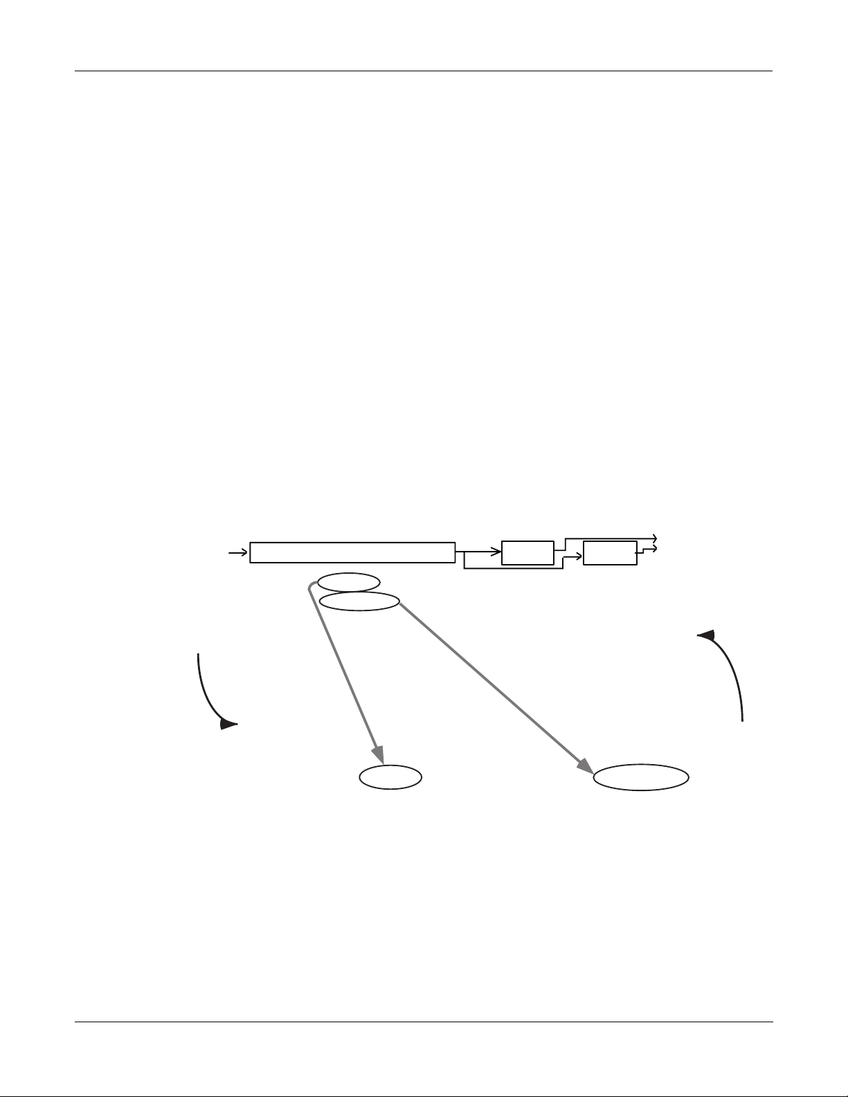
Inside KDFX
EditStudio:FXBUS|PAU:3|Free:1||<>FXBus:1|
FX1||29 Tabla|Room|||||||||Aux ||Mix
Wet/Dry :35%|||||Lvl:0ff |Lvl:0.0dB
Out Gain :0.0dB|||Bal:0%||||Bal:0%
Allocation:Auto
<more||INPUT||FXBUS||AUXFX||OUTPUT||more>
EditMultiFX:PARAM1|||||||||EffectSize:3/3
Algorithm:12|Panaural|Room
||||||||||||||||||||In|Gain|||:0.0dB
Wet/Dry|||:35%||||||Out|Gain||:0.0dB
Room|Size|:11.0m
Pre|Dly|||:4ms||||||Decay|Time:1.0s
HF|Damping:11840Hz
<more||PARAM1|PARAM2||||||||||||||||more>
Edit
Exit
About FX Presets
Instead, by using Bus Overrides, you can adjust these two parameters and hear what they
sound like while you are adjusting them without going into the FX Preset. When you save the
Studio, these parameter values are saved, but they are not part of the FX PresetÑthey are part
of the Studio. Therefore, the FX Preset remains unchanged (and if the FX Preset is in use
elsewhere, it hasnÕt changed there), but these two parameters in this particular FXBus have been
altered.
ÒWet/DryÓ and ÒOut GainÓ are the default Bus Overrides you will encounter most often, but in
some Algorithms and FX Presets, other parameters are accessed as Bus Overrides. For example,
on some Compressor Algorithms (as we saw in Chapter 2), the Þrst Bus Override is an In/Out
switch; and on some dual-channel delay and Þlter Algorithms, the overrides are separate
Wet/Dry controls for the left and right channels.
Making and Breaking Bus Overrides
Some Studios supplied with KDFX, when you Þrst encounter them, have the BusMods in place,
but they are not ÒengagedÓÑthat is, theyÕre not actually overriding anything, but instead
simply show the values of the corresponding parameters inside the FX Preset, unchanged. To
see this, choose an FX Preset on the FX Bus page and look at the values of the override
parameters: ÒWet/DryÓ and ÒOut GainÓ. Now go inside the FX Preset by highlighting the FX
PresetÕs name and pressing Edit, and Þnd those two parameters on the Þrst parameter page
(PARAM1). YouÕll see their values are the same as on the FX Bus page.
Figure 3-6. Bus Overrides in place, but not engaged
Press Exit to go back to the FXBus page.
3-13
Page 46

Inside KDFX
EditStudio:FXBUS|PAU:3|Free:1||<>FXBus:1|
FX1||29|Tabla|Room|||||||||Aux ||Mix
Wet/Dry :35%|||||Lvl:0ff |Lvl:0.0dB
Out Gain :0.0dB|||Bal:0%||||Bal:0%
Allocation:Auto
<more||INPUT||FXBUS||AUXFX||OUTPUT||more>
EditMultiFX:PARAM1|||||||||EffectSize:3/3
Algorithm:12|Panaural|Room
||||||||||||||||||||In|Gain|||:0.0dB
Wet/Dry|||:BusMod|||Out|Gain||:BusMod
Room|Size|:11.0m
Pre|Dly|||:4ms||||||Decay|Time:1.0s
HF|Damping:11840Hz
<more||PARAM1|PARAM2||||||||||||||||more>
Edit
Exit
About FX Presets
To engage a Bus Override, you have to use it at the FXBus level, which you do by moving the
parameter away from its nominal value on the FXBus page. Try that, and then go back inside
the FXPreset. YouÕll see that the value of the parameter youÕve changed is now shown as
ÒBusModÓ, meaning that the FXPreset parameter is under the control of the Bus Override. The
Bus Override will stay in effect even if you move the parameter on the FX Bus page back to its
original value.
.
Figure 3-7. Bus Overrides engaged
If you now change the parameter value from inside the FX Preset, it breaks the Bus Override. By
doing this, however, you have changed the FX Preset, and when you leave the FX Preset you
will be asked if you wish to save it. If you then save the FX Preset, the Bus Mod will be
permanently broken, but if you donÕt save the FX Preset, it remains in its previous state, which
means the Bus Mod remains intact.
Since Bus Overrides are part of the Studio, they are not saved permanently until the Studio is
saved.
Changing the BusOverrides
The default Bus Overrides that come up when you are working in a Studio are often
convenient, but you arenÕt required to use them as they are. You can assign any two of the FX
PresetÕs parameters to the Bus Overrides: Decay Time, Room Size, Pre Delay, etc., etc. (You
cannot, however, assign both Bus Overrides to the same parameter.) When you save the Studio,
the parameter choices you have made for the Bus Overrides on each FX Bus are saved, along
with their values.
3-14
Page 47

Allocation
Inside KDFX
Allocation
If you set up a Bus Override and adjust a parameterÕs value, and then change your mind and
assign a different parameter to that override, the value of the Þrst parameter (the one no longer
assigned to a Bus Override) will revert to its original valueÑthat is, the value set inside the FX
Preset. This can be a helpful feature, in that it means you can use Bus Overrides as a ÒwindowÓ
into an FX Preset by scrolling through the various parameters. But keep in mind that you canÕt
use this method to tweak parameters, because as soon as you move on, the parameter you
tweaked gets Òun-tweakedÓ.
Bus Mods vs. FX Mods
FX Mods are similar to Bus Mods, in that they control parameters within an object (in this case,
a Studio) without actually changing the object itself. But while Bus Mods work on an FX Bus
within a Studio, FX Mods come from outside the StudioÑthey are part of a Program or Setup,
and can control parameters anywhere inside the Studio associated with that Program or Setup
(including any of the FX Buses and FX Presets). More on this in Chapter 4.
Understanding Processor Allocation Units (PAUs) and how they work is very important for
using KDFX to its fullest potential.
WhatÕs a PAU?
The basic unit of signal processing in KDFX is the Processing Allocation Unit, or PAU. There are
a total of 4 PAUs that can be split among the four Insert FXBuses, and another 3 PAUs for the
AuxFX bus. These two sets of PAUs are distinct and not interchangeable.
The number of PAUs on an FX bus is determined by the Algorithm inside its FXPreset.
Different Algorithms require different numbers of PAUs, as shown in the ÒSizeÓ parameter at
the top of the screen when you are on the FXBus edit page:
EditStudio:FXBUS|Size:2
or inside an FX Preset:
EditFXPreset:PARAM1|||EffectSize:2/1
A simple delay, ßanger, compressor, exciter, or reverb, will need only 1 PAU. A complex phaser,
pitcher, or multiband tone control will need 2 PAUs. A really complicated reverb or graphic
equalizer may require 3 PAUs. Only a couple of specialized Algorithms require 4 PAUs.
The Allocation parameter on each FXBus page determines how many PAUs will be available
for the FX Preset assigned to that bus. If the parameter is set to Ò1Ó, then only FX Presets which
use Algorithms requiring 1 PAU will be available for the bus. If you try to assign an FX Preset
that requires more PAUs, its name will show up in parentheses, and the sound will pass
through the bus unprocessed.
If you know you want a certain FX Preset in a particular FXBus, you can select it, and then set
the Allocation parameter for that bus to match the PAU requirements of the FX Preset.
A PAU is a terrible thing to waste
Be careful not to set the Allocation parameter too high. If you set it on some bus to 3, for
example, and you are using an FX Preset on that bus that only requires 1 PAU, the other 2 PAUs
are being wasted, since they are not available to be assigned to other buses. The other busesÕ
Allocation parameters will not go higher than 1, and therefore no FX Presets whose Size is
greater than 1 can be selected for any of them.
3-15
Page 48

Inside KDFX
Allocation
Auto Allocation
PAUs are normally allocated on a ÒÞrst-come, Þrst-servedÓ basis. If you set one FXBus to a PAU
of Ò3Ó, then you will only be able to set the Allocation on the next Bus you set to Ò0Ó or Ò1Ó. If
you then set that second Bus to Ò1Ó, then you wonÕt be able to set a value greater than 0 for any
of the other Buses.
If you know you will not be using an FXBus, or you will be using it only as a ÒdummyÓ to route
signals to the Aux Bus or directly to the outputs, you can set its Allocation to Ò0Ó.
On any of the buses, you can set Allocation to ÒAutoÓ. Auto means that the PAU allocation for
that Bus will automatically adjust itself to the currently selected FX Preset. However, ÒAutoÓ
obviously cannot create PAUs when they are in use elsewhere, and Allocations that have been
set manually take precedence over Auto Allocations. So for example, if you set the Allocation of
FXBus1 to Ò3Ó, and set the Allocation of FXBus2 to ÒAutoÓ, the maximum number of PAUs
available to FXBus 2 is still only 1, and if you try to load a 2-PAU FX Preset into FXBus2, it
wonÕt work and the FX PresetÕs name will show up in parentheses.
If all busesÕ Allocations are set to Auto, then PAUs are not allocated Þrst-come, Þrst-served, but
instead are allocated in numerical bus order, with lower-numbered buses getting priority: if an
FX Preset requiring 3 PAUs is loaded into FXBus1, then only 1 PAU will be available for the
other buses, regardless of which FXPreset got assigned to which bus Þrst.
A ÒFreeÓ parameter is shown at the top of every FXBus page, telling you how many PAUs are
currently unassigned to any buses and therefore available.
Effect Size
While youÕre editing an FX Preset and selecting Algorithms for it, you are also kept apprised of
the PAU situation with the ÒEffectSizeÓ parameter in the upper-right corner of the screen. The
Þrst digit in this parameter is the number of PAUs the currently selected Algorithm requires,
and the second digit is the number that have been allocated to the bus, either manually or
automatically. If the Þrst digit is larger than the second, the Algorithm is not available, and if
you choose it, its name will show up in parentheses and the sound will pass through
unprocessedÑjust like an unavailable FX Preset on an FXBus page.
If the FXBusÕs Allocation is Auto, when you change the Algorithm inside the FX Preset editor,
both digits of the EffectSize display will change. If you call up an Algorithm that requires more
PAUs than are currently available, the second digit will change to Ò0ÓÑsince the Algorithm
canÕt be loaded, the PAUs are freed up for use elsewhere.
PAUs on the Aux Bus
The Aux Bus is a whole separate processor with 3 of its own PAUs. It has none of these issues,
since its 3 PAUs are assigned to it permanently. (There is a fourth PAU in the Aux Bus, but it is
used for mixing and routing, and so itÕs not available for FX Presets.)
Any FX Preset with a PAU requirement of 1, 2, or 3 can be used. When editing the AuxFX,
thereÕs no need for an Allocation parameter or a Free parameter. However, when you are
scrolling through Algorithms, the ÒEffectSizeÓ parameter will be displayed, with its second
digit always Ò3Ó. Should you try to access on the AuxFX bus one of those rare Algorithms
which requires 4 PAUs, the name of that Algorithm will be displayed in parentheses.
3-16
The Aux bus is generally used as a global processor, but it doesnÕt have to be. You can set up
one FXBus as a ÒdummyÓÑset its FXPreset to Ò0 NoneÓÑand send its output to the Aux bus,
and at the same time turn off the Aux sends from all the other buses. Now the Aux bus can
Page 49

Metering
Inside KDFX
Metering
function as an Insert FX Bus, with 3 PAUs all its own. So if you run into trouble with PAUs on
the Insert FX buses and can sacriÞce a global effect, this is one solution.
KDFX has two kinds of metering: arrow meters and bar-graph meters.
Arrow meters
All Input and FXBus pages have rudimentary signal meters, as weÕve seen. On the Input pages,
the arrow next to the input letter ßashes when there is signal present at the input. On the Insert
and Aux FXBus pages, the arrow next to the FXBus number ßashes as long as there is signal
being processedÑin effect, itÕs an output meter. The arrows ßash whenever the signal level
exceeds 14 bits below full scale, which is -84 dB relative to the maximum level the KDFX can
handle. Since typically the K2500 is operated with about 20 dB of headroom, this translates to
about -64 dB relative to normal operating level
.
EditStudio:AUXFX|
||Aux||103|||||||
Bar-graph meters
In addition, a number of KDFX Algorithms include a fast visual metering system for
monitoring what the Algorithms are doing. Many of these Algorithms deal with dynamics
control like compression and limiting. An example is Algorithm 950, HardKneeCompress.
Meters are most often found on the PARAM2 page of the FXPreset Editor:
EditFXPreset:PARAM2|||HardKneeCompress
Atk|Time||:0.0ms||||Ratio|||||:3.0:1
Rel|Time||:510ms||||Threshold:-28.0dB
SmoothTime:0.1ms||||MakeUpGain:0.0dB
Signal|Dly:0.0ms
||||||||||||||||
||||||-dB|60||40||*|16|*|8|4|0
<more||PARAM1|PARAM2|||||||||||||||more>
In this Algorithm, the meter is showing the gain reduction that the compressor imposes on the
signal coming into it.
Metering is also used for other purposes in some other Algorithms, for example 902 LFO Sweep
Filter. In this Algorithm, the meters show the current center frequency of the left and right
Þlters as they sweep up and down the spectrum:
EditFXPreset:PARAM2||||LFO|Sweep|Filter
FilterType:Lowpass||Min|Freq||:58Hz
Resonance|:20dB|||||Max|Freq||:8372Hz
L|Phase|||:0.0deg|||R|Phase|||:0.0deg
|||||||||
Reduction
L|||||||||||||||
0Hz||2k|||4k|||6k|||0Hz||2k|||4k|||6k|||
<more||PARAM1|PARAM2|||||||||||||||more>
Meters use up a certain amount of KDFXÕs processing power, although less than a whole PAU,
and so they are only used only in Algorithms where they are particularly appropriate.
3-17
|||
R|||||||||||||||
|
Page 50

Inside KDFX
Output section
Output section
Insert
FXBuses
Pre FXBus2
FXBus2
Pre FXBus3
FXBus3
Pre FXBus4
FXBus4
å
Aux
effect
Mixer
FXBus1
Pre FXBus1
Off
Aux
Mix
Physical outputs
A
Output B
Figure 3-8. Outputs
EditStudio:OUTPUT|||||||||||||||||||||||
Mix|Lvl:0.0dB||||||Output|A:Mix
Mix|Bal:0%|||||||||Output|B:Off
|||||||||||||||||||Output|C:Off
|||||||||||||||||||Output|D:Off
<more||INPUT||FXBUS|AUXFX||OUTPUT|more>||
In the Output section, the various signal paths are routed to the K2500Õs physical outputs. Each
of the four output pairs, A, B, C, and D, has a selector switch to determine which signal it will
carry. All signals are stereo. The choices are:
Output C
Output D
3-18
Page 51

¥ Off. No output.
)
¥ PreFXn, which is the signal coming into the FX Preset on FXBus1, 2, 3, or 4. Depending on
how your Inputs are set up, this could be one signal or many. If more than one Input is
assigned to FXBusn, then all of the EQs and pan/width/balance settings of the Input
modules assigned to the FXBus are active on this signal pathÑbut the FX Preset is not.
¥ FXBusn, the direct output, post-FX Preset (i.e., the return), from any of the four Insert
FXBuses.
¥ Mix, the signal from the Mix output, which can include the sum of any or all of the Insert
FXBuses, and/or the Aux Bus. The Level and Balance parameters on this page control this
output.
¥ AuxFX, the outputs of the Aux Effects bus.
There are no restrictions on the settings on this page. If you like, all four outputs can be
carrying the same signal: PreFX1, for example.
Separate Analog and KDS Outputs
The K2500Õs separate analog outputs (the four pairs) and KDS outputs (also four stereo pairs)
are wired in parallel and are ÒliveÓ at all times. The selectors on the Output page affect both the
separate analog and KDS outputs.
Inside KDFX
Output section
Analog Mix Output
The K2500Õs Analog Mix output, as it always has, combines the four output pairs into a single
stereo analog pair. If a plug is inserted into any of the other analog output jacks, however, the
signal going to that output jack is removed from the Analog Mix bus, and does not appear at
the Analog Mix output.
The Internal Effects processor is still active on the ÒKDFX-AÓ output bus coming from the
K2500Õs Program Editor, and can be used in conjunction with KDFX. For more information, see
Chapter 6.
internal Effects
processor
K2500 physical
outputs
KDFX outputs
inserting jack breaks
connection to Mix out
Mix out
(analog)
ABCD
A
(analog/KDS)
(AES/EBU
Ñsee text
B
(analog/KDS)C(analog/KDS)D(analog/KDS)
Figure 3-9. Analog, KDFX, and AES/EBU outputs
3-19
Page 52

Inside KDFX
Output section
AES/EBU Outputs
The way the AES/EBU outputs in a K2500 with KDFX is somewhat different from the way they
work in a K2500 without KDFX.
The AES/EBU digital output of the K2500 (a single stereo pair) is normally in parallel to output
pair A. It gets whichever signal is assigned to that pair.
However, if you have the Sampling Option installed in your K2500, you have more options.
These options are determined on the SampleMode pageÑfrom the Program or Setup mode,
press the ÒSampleÓ soft button.
SampleMode||Samples:18432K||Memory:218K|
Sample:None||||||||||||||||||||||Src:Ext
Input:Digital||Time:5s|||||||||||Out:A/D
If the ÒOutÓ parameter on the SampleMode page (which you can only see when the ÒInputÓ
switch is set to ÒDigitalÓ) is set to ÒDirÓ (Direct), then the AES/EBU output behaves normally
and is in parallel to output A.
However, when the Out parameter is set to ÒA/DÓ, then the AES/EBU output mirrors
whatever signal is coming into the samplerÕs analog input. This, in turn, is set by the ÒSrcÓ
parameter in Analog input mode. (In Digital input mode, the ÒSrcÓ parameter has a different
function.) If this parameter is set to ÒIntÓ, then the signal from the K2500Õs Mix output is being
fed back into the samplerÑand thus the AES/EBU outputs will carry the identical signal that the
analog Mix outputs are carrying. This is useful when you want to be able to use the Internal
effects processor with the digital outputs. More on this in Chapter 6.
This feature is also helpful when re-sampling the K2500, that is, sampling its outputs to create a
new, more complex sample. If the Out parameter is set to ÒDirÓ, then re-sampling will be very
quiet and clean, but only the output-A signal will be re-sampled. If it is set to ÒA/DÓ, then the
re-sampled sound will consist of all of the analog outputs, plus the Internal effects processor,
and the potential for noise build-up is higher.
If the Analog Src parameter is set to ÒExtÓ, then the signal that appears at the AES/EBU output
is the signal coming into the K2500Õs external analog inputs, and the K2500 is acting as a very
fancy, very high-quality A/D convertor.
The following diagram and table should help you understand the possibilities:
KDFX output A
Dir
Digital Out
A/D
K2500 Mix
output
Int
Analog Src
Ext
internal Effects
processor
K2500 analog
input
3-20
AES/EBU output
Figure 3-10. AES/EBU output conÞguration.
Page 53

Table 3-1. AES/EBU output switch settings
Digital ÒOutÓ switch Analog ÒSrcÓ switch WhatÕs on the AES/EBU
Dir n/a KDFX output A
A/D Int K2500 Mix output
A/D Ext K2500 analog input
Digital Word Length
The K2500 is capable of producing 20-bit digital audio signals. While normal 16-bit digital
audio provides a maximum dynamic range of about 96 dB, adding the extra four bits adds
some 24 dB to the dynamic range. There are an increasing number of products on the market
that can handle 20-bit digital signals, including tape and hard-disk recorders, mixers, and
signal processors, and the K2500 can talk to these devices with the highest degree of Þdelity.
Inside KDFX
Output section
output
Dither
The ÒDigOutÓ parameter at the bottom right corner of the EffectsMode page turns on this
feature, and selects between 16-bit and 20-bit operation.
This setting determines the word length on the KDS eight-channel output, and also on the
AES/EBU output, provided it is in ÒDirectÓ mode (as set on the SampleMode pageÑsee the
previous section).
If you are using the K2500 with a Kurzweil DMTi, this switch should be set to Ò16 BitÓ, since the
DMTi currently operates only in 16-bit mode. However, if you are connecting the AES/EBU
output to a 20-bit (or more) capable device, set the switch to Ò20 BitÓ and you can take
advantage of the signiÞcantly reduced noise ßoor.
Note that the switch does not affect any of the K2500Õs inputs: those are always operating in
16-bit mode.
Dithering is a technique in which a small bit of noise is added to a digital signal when you are
shortening the digital word length, e.g., from 20 bits to 16 bits. Its effect is to remove
quantization distortion that otherwise may result in strange modulation artifacts at low levels.
The subjective effect, paradoxically enough, is often that the apparent noise ßoor of the
processed signal is lowered. The Dither parameter at the bottom left of the EffectsMode page
allows you to select between different digital noise ßoor characteristics. No setting is superior
to anotherÑeach one is a tradeoff between perceived noise level and artifacts. Here is a brief
explanation of each setting:
FlatÑthe digital noise ßoor is spectrally ßat, so it's a good choice for re-sampling the K2500Õs
own output, as there will be no adding of noise in the process. This is sometimes known as
ÒtriangularÓ dither.
Minimum, Medium, MaximumÑthese utilize noise-shaping in varying degrees. The noise
ßoor has been essentially equalized to make it softer at midrange frequencies, and louder at
bass and treble frequencies. The overall power level of the noise is actually higher than at the
Flat setting, but due to the ear's spectral response at low levels, the noise ßoor appears lower at
these settings.
3-21
Page 54

Inside KDFX
Gain Staging
They are not as good a choice as Flat for re-sampling, since the boosted noise may become quite
noticeable if the sample is played transposed down a couple of octaves. In addition, repeated
re-sampling would cause build-up at the boosted frequencies.
NoneÑno dither. This is provided primarily for completeness. You generally never want to use
this setting, unless you are studying dither in a classroom, or you want to speciÞcally hear
digital artifacts. Low level signals are extremely distorted using this setting.
Gain Staging
Proper gain stagingÑthat is, keeping track of gain changes as the signal moves through the
various components of KDFXÑis helpful in geting the most out of KDFX.
While KDFX has plenty of headroom available for most processing, you may run into problems
of digital clipping if extremely high Þlter resonances or large amounts of distortion are present
on an FX Bus. Most headroom problems are best dealt with as ÒlocallyÓ as possibleÑrather
than turning down a ProgramÕs output to reduce clipping, youÕre usually better off turning
down the offending BusÕs In or Out Gain (using a Bus Override to get inside the FX Preset) or
the Aux and/or Mix outputs.
Another potential problem is that the gain of a Program might change drastically when you
change Studios, due to an effect being added or removed that itself changes the gain, such as
distortion, quantization, or compression. In these cases, again, it can help when you are
designing the studio to adjust the FX PresetÕs In or Out Gains or the BusÕs Aux or Mix outputs
to balance the levels, so that the volume coming from the Program is roughly the same whether
or not the effect is present. You can check your work by scrolling through different Studios or
FXPresets (particularly the factory ones) and making sure the levels donÕt jump out at you or
disappear.
As we mentioned earlier, hard-panning a signal can have an effect on the gain. The Pan,
Balance, and Width controls all have constant power curves, so that the combined signal level
doesnÕt change when you move the signals from side to side. This means, however, that when
you use these controls to isolate individual channels through an entire Studio by hard-panning
the signals, there can be a substantial increase in gain. Each stage of hard-panning adds 3 dB, so
if youÕve panned the Input send, the Aux send, the Mix send, and the Mix output all to 100%,
youÕve boosted the signal by 12 dB. If this happens, you might want to back off the level at
various stages to keep the signals from getting too hot.
3-22
Page 55

Saving Studios and other objects
Saving
Saving a Studio or an FX Preset is handled the same as any other K2500 objectÑsee Chapter 5
of the K2500 Performance Guide if you need help with this.
To save an object, from any of the editing pages within the object, press <more or more>, until
you see the Þle-management pages:
<more||Name|||Save|||Delete|Dump|||more>
Name lets you rename the object, using the standard K2500 naming window. Save lets you
save the object to its present slot or to a different one, and also gives you the option of
Renaming it before saving it, or accessing the Object utilitiesÑsee Chapter 13 of the Performance
Guide.
Delete deletes the object from RAM. If it is in a slot where there is a ROM Studio or FX Preset,
then the slot will revert to the ROM Studio or FX Preset.
Dump performs a MIDI System Exclusive dump of the object over the MIDI Out cable for
external storage.
Inside KDFX
Saving Studios and other objects
The Save option is automatically invoked if you have done any editing within an object and
you press Exit.
Do I Always Have to Make a New Studio?
While it may sound as if every time you make a change in a Studio parameter, you have to
create a new Studio to save it, this is not necessarily true. Studios do take up room in Program
RAM, and although the number of Studios that can be maintained inside the K2500 is large, it is
not unlimited. Besides, it can be very cumbersome keeping track of a large number of Studios
which have only small differences between them.
A way to avoid this problem is to use Program or Setup mode, and use ÒFXModsÓÑStudio
parameter controls that live inside a Program or SetupÑto make changes in the Studio
parameters. When you load the Program or Setup, the Studio changes accordingly. This means
you donÕt have to save each variation in the Studio as a separate Studio; the variations live in
the Program or Setup.
MoreÑmuch moreÑon this in Chapter 4.
Disk Functions
Studios and FX Presets are loaded from and saved to disk exactly the same as other K2500
objects. FX Presets are dependent objects within Studios, so when you save a Studio, you are
given the opportunity to save the dependent FX Presets as well. (Algorithms are in ROM, so
they donÕt need to be saved.) Again, see Chapter 13 of the Performance Guide if you need help.
3-23
Page 56

Inside KDFX
Saving Studios and other objects
3-24
Page 57

Chapter 4
Real-time Control of KDFX
KDFX Studios can be static, as we saw in the last chapter, but they donÕt have to be. One of the
most powerful features of KDFX is the ability to change any of the operating parameters in a
Studio in real time. Mix levels and pans, eq values, effects parameters, and almost any other
settings can be controlled dynamically and smoothly, giving KDFX a high degree of ßexibility
in performance and automation.
KDFX parameters can be controlled from:
¥ the K2500Õs sliders, wheels, ribbons, and pedals
¥ external MIDI sources like another controller or a sequencer
¥ internal functions like LFOs, envelopes, and FUN generators.
Real-time control of a Studio is called ÒEffects ModulationÓ, and a link between a Program or
Setup and a Studio parameter is called an ÒFXModÓ.
Linking to Programs and Setups
If youÕre familiar with real-time control of the original Internal K2500 Effects, youÕll be happy to
know that real-time control of KDFX Studios works the same way.
Real-time KDFX Studio control normally originates within a Program or Setup. For the link
between a Studio and a Program to work, the FX Mode parameter on the Effects page must be
set to ÒProgramÓ. You also need to set an FX Channel, and the Program controlling KDFX must
be assigned to this channel.
EffectMode||||Xpose:0ST|||||<>Channel:1|
FX|Mode:Program
FX|Chan:1
Dither|:Medium||||||DigOut|:16 Bit
Octav-|Octav+|Panic||||||||Chan-||Chan+
If you want to link a Studio and a Setup, the FX Mode parameter on the Effects page must be
set to ÒSetupÓ. There is no Channel parameter in this modeÑKDFX will always link to the
current Setup.
Setting the FX Mode parameter on the Effects page to ÒAutoÓ means that it will follow
whatever mode the K2500 is inÑProgram or SetupÑwhich can be particularly useful when
you are switching between Programs and Setups in a Quick Access bank, or when you just
donÕt want to worry about which mode youÕre in.
Notice that when FX Mode is set to Program or Setup, the Studio is not shown, as it is when the
FX Mode is set to Master. So you canÕt go into a Studio and edit it from this pageÑyou have to
go through the Program or Setup, from its KDFX page. (The Internal effects arenÕt shown either,
and the procedure for editing them is the same.)
4-1
Page 58

Real-time Control of KDFX
Linking to Programs and Setups
Note: When FX Mode is set to Auto, and you are on the Effects Mode page, you are actually in
Master mode. But donÕt screw up your brain thinking about thisÑweÕll get back to what it
means at the end of the chapter.
☛For the sake of clarity, during most of this chapter we will only talk about linking KDFX
to a Program. The procedures for linking KDFX to a Setup are essentially identical, except
for the setting of the FX Mode.
The KDFX pages
If you look inside any Program, you will see several new pages to handle the Studio and KDFX
control assignments. Open up a Program with the Edit button and press more> until you see
this at the bottom of the display:
<more||KDFX|||FXMOD2|FXMOD3|FXMOD4|more>
These are the FXMod setup pages, and in fact there are eight of themÑpress more> again to see
the others.
<more||FXLFO|FXASR||FXFUN||ImpFX||more>
Go back to the Þrst set (press <more), and press the KDFX soft button to look at the Þrst of the
FXMod setup pages. Unless youÕve changed your Marked pages since installing KDFX, you
can also press Jump to get to this page.
EditProg*KDFX|||||||||||||||||All|Layers|
Studio:278|Hall+flange+rm||
Bus:|Param:|||||Adjust:||Source:||Depth:
FX1||Wet/Dry||||12%wet|||MWheel|||40%wet
FX2||Fdbk|Level|25%||||||MIDI23|||60%
InA||EQ1|Bass|G|0.0dB||||MIDI24|||21dB
<more||KDFX|||FXMOD2|FXMOD3|FXMOD4|more>
The top line tells us weÕre in the KDFX section of the Program Editor. The second line shows the
Studio that is linked to this Program. Any changes made on this page do not directly affect the
Studio, they only affect this ProgramÕs control over the Studio.
The last three lines (ignoring the Soft buttons) show us some of the FXMods that are active in
this Program: one is controlling Wet/Dry mix on insert FX bus 1, one is controlling feedback
level on insert FX Bus 2, and one is controlling the Bass Gain on the Þrst EQ of Input A.
Looking into the Studio
You can go into this Studio, to see what the parameters are doingÑa good idea when you are
setting up FXMods so you understand them in contextÑor to alter a Þxed parameter. You do
this without leaving the Program Editor: highlight any parameter on this page and press Edit.
When you are done with the Studio, pressing Exit will bring you back to this page. If you have
made any changes in the Studio, you will be prompted to save the Studio, and if you donÕt do
so, the changes will be disregarded.
4-2
If you do save the Studio, either in the same numbered location or a new one, the new Studio
will now be linked to this Program. If you have changed the location of the Studio, then youÕll
also have to save the Program when you leave the Program Editor, so that the Program knows
which Studio to link to the next time you call it up.
Page 59

Setting up FXMods
The KDFX page allows three different FXMod control assignments to be made. More FXMod
assignments are available on the FXMOD2, FXMOD3, and FXMOD4 pages, each of which has
Þve setups. This gives a grand total of 18 Studio parameters that can be subjected to real-time
control. DonÕt worry, you donÕt have to use them all. (And if you run out, thereÕs always System
ExclusiveÑsee Appendix C.)
Bus assignments
The Þrst column lets you choose which Bus inside the Studio you want this FXMod to control:
Input A, B, C, or D (if any of the Inputs are set to Mono, you will get to choose individual
channels, for example A/L and A/R); FXBus 1, 2, 3, or 4; the AuxFX Bus; or the Mix bus.
Parameter assignments
The second column chooses the speciÞc parameter on the selected Bus that you want to control.
Scrolling through the choices shows that this selection is context-sensitive: it shows only
parameters that are being used in the current Studio on the selected Bus, so you canÕt make
assignments to irrelevant or non-existent parameters. It ÒknowsÓ which EQs are active, and
what modes they are set to; which Input sends are assigned and whether the sends are in Pan
or Balance mode; what parameters are being used in the FX Preset on the particular Bus; etc. If
you need to know more about how the Studio is set up, you can go into it and look around, as
explained above.
Real-time Control of KDFX
Setting up FXMods
HereÕs an example: set the FX Studio to 201*RngMd/PFD/Plt which we looked at in Chapter 2.
Set the Bus on the Þrst line to InA. Set the cursor under ÒParam:Ó and scroll the choices. They
correspond exactly to the parameters available in the Input Editor page: level and frequency for
the two EQs, and SendLvl, Pan, and Width for the two FX sends. Note that you cannot change
the FXBus assignments on an Input from here; you must do that within the Studio itself.
Change the Bus to FX1, and now all of the parameters from the FX Preset on FXBus 1 are
available for selection, including Mod Mode and the various settings for the PresetÕs internal
oscillators, as well as the busÕs output controls: Mix Level, Mix Balance, Aux Level, and Aux
Balance. Change the Bus to AuxFX, and the Aux FXBusÕs parameters are available: levels,
delays, room types, etc.
Setting the Bus to Mix makes available the Level and Balance controls from that page.
What canÕt be controlled
Parameters that would involve a major reconÞguration of the Studio cannot be assigned an
FXMod and modiÞed with a real-time controller. These include:
¥ Bus assignments on the Input pages
¥ Selection of FX Presets on the FXBus pages
¥ Allocation on the FXBus pages
¥ Selection of Algorithms within the FX Presets
¥ Bus assignments on the Output page
If you want to be able to change any of these on the ßy, you will have to create a new Studio,
link it to a different Program or Setup, and then call it up using a Program Change command.
4-3
Page 60

Real-time Control of KDFX
Setting up FXMods
In addition, there are a few parameters that can cause serious glitching if they are changed in
real time. The most common of these are the ÒRoom TypeÓ settings in reverb Algorithms, which
can create clicks and pops when they are changed while signal is passing through them. While
there is nothing in the software to prevent you from assigning an FXMod to Room Type, you
need to be cognizant of the potential consequences. See ÒStatic FXModsÓ later in this chapter.
ÒAdjustÓ setting
The Adjust setting is the starting value of the selected parameter when it is under KDFX
control, similar to the Entry value of a controller in a Setup. This might very well be different
from the value of the parameter when the Studio is not under FXMod control, so donÕt get
confused. If you are in Program mode, and this is the current Program, the Adjust value takes
precedence over the StudioÕs Þxed value, and itÕs the Adjust value that will be called up when
you call up the Program.
Source
The Source parameter determines which real-time controlÑinternal, MIDI, etc.Ñis going to
affect the selected Studio parameter. As with all K2500 real-time controls, the range of control
sources is very large:
¥ OFF (the parameter is not affected by any source and stays at its ÒAdjustÓ value)
¥ ON (the parameter is set to the maximum value determined by adding the Adjust and
Depth values)
¥ MIDI Continuous Controllers 1-95*
¥ Channel State
¥ Pressure
¥ PitchWheel
¥ the usual software controllers, as described in Chapter 6 of the K2500 Reference Guide:
ASRs, FUNctions, Clocks, LFOs, Internal Controls, Random Generators, etc.
*Under some circumstances, particularly when the K2500 is in Setup mode, there are certain
restrictions on which MIDI sources you can use. This is explained later in this chapter, in the
section ÒEnabling Controllers in Setups and ProgramsÓ.
Dedicated FXMod control sources
A few new control sources, usable only within FXMods, have been added to the list:
¥ FXLFO1, FXLFO1ph, FXLFO2, and FXLFO2phÑtwo LFOs and their phases.
¥ FXASR1 and FXASR2Ñ two three-stage (Attack/Sustain/Release) envelopes with
selectable triggers and Normal, Hold, and Repeat modes.
¥ FXFUN1, FXFUN2, FXFUN3, and FXFUN4ÑFunctions. Yes, more Fun with KDFX!
These LFOs, ASRs, and FUNs work exactly the same way they do in any other part of a
Program, except these are extra control sources for use only with FXMods, and are not available
for other VAST Program functions. They are global for all of the FXModsÑeach Bus does not
have its own.
4-4
Their parameter values are saved with the Program. As we saw earlier, you get to the pages for
their parameters by pressing the more> soft button until you see these soft buttons:
<<<<mmmmoooorrrreeee|FFFFXXXXLLLLFFFFOOOO|FFFFXXXXAAAASSSSRRRR|FFFFXXXXFFFFUUUUNNNN|IIIImmmmppppFFFFXXXX|mmmmoooorrrreeee>>
>>
Page 61

Depth
Real-time Control of KDFX
Setting up FXMods
As usual in the Program Editor, you can also get to these pages directly from the KDFX page or
one of the FXMOD pages: select one of those parameters as a Source, and then press Edit.
Tempo-based parameters
There are several different ways KDFX can respond to tempo information, from the internal
sequencer or an external one. These are discussed later in this chapter.
The Depth parameter lets you specify the amount of change in value that the real-time control
will make to the target Parameter, using the Adjust value as a minimum or starting point. The
amount of change can be positive or negative, and Depth values are displayed in the context of
the selected Studio Parameter: seconds, dB, %, Hz, cents, etc.
At the maximum setting of the Source (for example, Mod Wheel all the way up), the value of
the parameter = Adjust + Depth. So if the parameter is Out Gain, the Adjust is 1.0 dB, the
Source is Mod Wheel, and the Depth is 4.0 dB, then at the Mod WheelÕs highest point, the
output gain will be 5.0 dB.
For Source values less than maximum, the formula is: parameter = Adjust + (Depth x Source),
where the Source is considered to be varying between 0 and 1 (or in some cases, such as Pitch
Wheel, between -1 and +1). So using the same example, when the Mod Wheel is halfway up
(MIDI value 64), the gain is 1.0 + (4.0 x 1/2) = 3.0 dB, and when it is all the way down (MIDI
value 0), the gain is 1.0 + (4.0 x 0) = 1.0 dB.
The formula works the same way for negative Depth values. Given the same example, but with
a Depth of -4.0dB, at the Mod WheelÕs minimum point, the gain will be 1.0 dB; at its halfway
point it will be 1.0 + (-4.0 x 1/2) = -1.0 dB; and at its maximum point it will be -3.0dB.
Showing whoÕs in control
When you are in Program or Setup mode and you look inside the current Studio or its FX
Presets, any parameters that are under FXMod control will not display numerical values, but
instead will say ÒFXModÓ. DonÕt touch any of those parameters for nowÑweÕll explain why in
a moment.
EditFXPreset:PARAM1|||||EffectSize:3/3
Algorithm:12|Panaural|Room||||||||||
||||||||||||||||||||In|Gain|||:0.0dB
Wet/Dry|||:FXMod||||Out|Gain||:2.0dB
Room|Size|:FXMod
Pre|Dly|||:4ms||||||Decay|Time:1.7s
HF|Damping:14080Hz
<more||PARAM1|PARAM2|||||||||||||more>
☛Note that if you look at the Studio when FX Mode is in ÒMasterÓ, the FXMods will not be
displayed, because the FXMods are not in effect! DonÕt get confused by thisÑthe FXMods will
return when you go back into Program or Setup mode.
4-5
Page 62

Real-time Control of KDFX
Setting up FXMods
Breaking the Links
When FX Mode is in ÒProgramÓ or ÒSetupÓ and you are in the Studio Editor, if you change a
parameter that has been assigned an FXMod, it ÒbreaksÓ the linkÑthe parameter is no longer
under FXMod control, but is now a static value. If you now save the Studio (either in the same
location or a different one), the link stays broken. However, if you leave the Studio without
saving it, and go back to the FXMod pages of the Program editor, the link automatically reestablishes itself.
If you change the FX Preset on an FXBus, the FXMod links to the FX Preset on that bus may or
may not break. If the FX Preset youÕre calling up uses the same Algorithm as the Preset youÕre
leaving, the links will stay intact. If it uses a different AlgorithmÑeven a similar oneÑthe links
will break. On the other hand, if you are inside an FX Preset, and you change its Algorithm, that
breaks the links. Again, the links will be re-established if you leave the Preset without saving it.
If you have FXMod links to the Aux and Mix parameters on an FXBus, they do not get
interrupted when you change the FX Preset on that bus.
The same rule applies when you are on the KDFX page in a Program or Setup and you change
the Studio. If you have links to the Input and Output pages and the Level parameters on the
FXBus pages, they will be retained, but links to processing parameters will only be retained on
a given FXBus only if the Algorithm inside the FX Preset on that bus isnÕt changed.
What about Bus Overrides?
Bus Overrides are transparent, as far as KDFX is concerned. Any FXMods that involve a
parameter inside an FX Preset are set up directly between the Program and the FX Preset itself.
If a parameter under FXMod control happens also to be assigned a Bus Override, it doesnÕt
make a difference to KDFXÑthe FXMod in the Program will control the parameter as if the Bus
Override wasnÕt there.
However, Bus overrides are still active within a Studio, and changing a Bus override value in a
Studio will, as usual, change its associated FX Preset parameter. Should there be an FXMod
which is also assigned to that same parameter, the FXMod link will be broken, just as if you reset
the parameter from inside the FX Preset.
For example, letÕs say you have a Bus Override on FXBus1 assigned to Wet/Dry for the reverb
FX Preset that is on that bus. You also assign an FXMod from a Program to that same Wet/Dry
parameter on FXBus1. Now if you change the Bus Override, thus changing the Wet/Dry value
of the reverb, the FXMod link to that reverb will be broken, and wonÕt re-establish itself unless
you re-assign it from the Program, or else leave the Program without saving it.
Using FXMods so you donÕt have to change Studios
In the previous chapter, we mentioned that FXMods are a good way to get around the need to
create a new Studio every time you want to make a small change in a StudioÕs parameters. The
same Studio can be used for many different purposes if you use FXMods to control it. FXMods
can set the gain of the signals going to the various FXBuses, set panning and output levels of
the signals from the Buses, conÞgure the mix going to the Aux bus, and even turn FXBuses on
or off, as well as set processing parameters within the FX Presets.
4-6
Since any parameter except the ones that re-conÞgure a Studio (see ÒWhat CanÕt Be
ControlledÓ, earlier) can be under FXMod control, the amount of variation between the various
Program- or Setup-controlled versions of a single Studio can be very great.
Page 63

Importing Studios from another Program or Setup
Static FXMods
Static FXMods, that is, FXMods that are just going to be used to Òset and forgetÓ Studio
parameters when a Program or Studio is called up (as opposed to dynamically controlling
them), are easy to set up. On the FXMOD page, select the Bus and Parameter you want to
control, set the Adjust value to the Parameter value you want, and set Source to ÒOFFÓ. When
you are done, Save the Program or Setup normally. Now whenever you select the Program or
Setup, the Parameters in the FXMods will be immediately reset to the values youÕve speciÞed.
Room Type and other potentially glitch-producing parameters work much better as static
FXMods than they do under dynamic control. If you need to change a Room Type in a reverb
when you change a Program, you can do so with a static FXMod without hearing horrible
glitches, as long as you make sure there is no signal passing through the reverb at the moment
of the Program change.
Importing Studios from another Program or Setup
If you have a killer Studio with FXMods set up in one Program (or Setup) and you want to use
the same Studio and FXMods in a different Program, you donÕt have to rebuild the Studio by
hand: you can copy Studios between Programs or Setups in one operation.
Real-time Control of KDFX
Scroll with the more buttons until the soft button ImpFX appears. Press it, and youÕll see this:
Edit Program:Import KDFX
From|Program||200*My|Orchestral|Studio||
(Studio 41|auxChorTube|Plt|||)|
Prog||Setup||||||||||||||||||Import|Cancel
Use the soft buttons at the left to select either a Program or a Setup as the source for the Studio
and FXMods you are importing. Select the number of the Program or Setup you want to import
from. As you change the Program or Setup, the Studio associated with each Program or Setup
will display in parentheses below the Program or Setup.
The Studio will also kick in, so you can hear it affecting the Program youÕre listening to.
When youÕve chosen a Program or Setup to import a Studio from, press the Import soft button.
ÒKDFX fromÉimportedÓ will ßash on the screen, and you will be returned to the Program
Editor of the Program or Setup you are working on.
Studios from Setups can be imported into Programs without restriction, and vice versa.
FXMods on Imported Studios
When you import a Studio into a Program (or Setup), the FXMods connected to the Studio
youÕve imported come along with it. They will replace the FXMods that are in the Program
youÕre importing into. It doesnÕt matter if there were more FXMods in the Program youÕre
importing into than in the one youÕre importing fromÑeven if the Program youÕre importing
from has zero FXMods, the ones that were in the Program youÕre importing into are all erased.
4-7
Page 64

Real-time Control of KDFX
Using KDFX live from the K2500 keyboard
Using KDFX live from the K2500 keyboard
The sliders and wheels on the K2500 keyboard, and the pedals connected to the keyboard, can
be extremely useful with KDFX, if you assign FXMods to the K2500Õs controllers. The ribbon,
for example, can be used in a ÒPitcherÓ FX Preset to change the pitch of the signal, while sliders
and pedals (as we saw in Chapter 2) can be used to control reverb time, ßanger feedback, eq, or
any of the myriad parameters available in KDFX.
KDFX in Setup Mode
If you are playing the K2500 in Setup mode, then itÕs probably a good idea to have KDFX also in
Setup mode, or in Auto mode. This can help prevent confusion that can arise when mixing
modes.
Like Programs, every Setup has a set of FXMod routings associated with it. These are identical
to the routings available in Programs: there are four FXMod pages, three dedicated FX function
pages, and an Import FX page. The procedure for setting up the routings is the same as in a
Program. KDFX settings can be imported into a Setup from either another Setup or a Program.
When KDFX is under Setup control, any FXMods that are in the Programs within the Setup are
ignored. If you have a Program that contains a Studio and FXMods that you would like to use
while playing a Setup, import the KDFX from the Program into the current Setup.
MIDI Control and Setup Mode
YouÕll notice that when you set FX Mode to ÒSetupÓ, FX Chan goes to ÒNoneÓ, and canÕt be
changed. The MIDI receive channel for controlling KDFX is not determined here, itÕs
determined in the Setup itself: itÕs the channel that Zone 1 of the Setup is receiving. Any
incoming MIDI commands on other channels, while they may play sounds in the Setup, will not
affect KDFX parameters.
There may be circumstances in which you donÕt want KDFX to be in Setup mode while you are
playing a Performance Setup. For example, you may want to have an external sequencer
controlling KDFX, while you are playing along on the K2500 keyboard in Setup mode. Or you
may just want to be able to play in Setup mode and not worry about changing Studios when
you change Setups
In these cases, it makes sense to set the FX Mode to ÒProgramÓ. You will have to set an FX
Channel, and the Program that is in the Zone assigned to the FX Channel will control KDFX. If none
of the Zones are assigned to the FX Channel, then the Setup will not be able to control KDFX.
However, an external device sending MIDI data to the K2500 on the FX Channel will be able to
control KDFX.
HereÕs an example: say a Setup has three Zones, which are assigned to channels 2, 4, and 6
respectively. If FX Chan is set to 6, then the FXMods in the Program in Zone 3 will be active. But
if none of the ZonesÕ channel assignments match the FX ChannelÑsay itÕs set to 16Ñthen
nothing you do on the K2500 will control the FXMods. However, an external sequencer sending
on channel 16 will control the FXMods, and the Program that is on channel 16 will determine
what they are.
Using an External Keyboard with Setup mode
4-8
As we mentioned in Chapter 2, using a K2500 (or more commonly, a K2500R) with an external
MIDI keyboard presents some special situations. If you are not using this conÞguration, you are
advised to skip this section, because it gets a little hairy (unless you are morbidly curious about
such things, in which case, read on!)
Page 65

Real-time Control of KDFX
Using KDFX live from the K2500 keyboard
Playing a Setup with a single-channel keyboard
Playing Setups normally requires a multi-zoned/multichannel keyboard like the K2500 itself or
a Kurzweil PC88. However, it is also possible to play Setups from a conventional, singlechannel MIDI keyboard, thanks to a parameter called ÒLocal Keyboard ChannelÓ
(LocalKbdCh), which is found on the MIDI:Receive page. If you set this parameter to the
transmitting channel of the external keyboard, then the K2500 takes all incoming MIDI data on
that channel and treats it as if it was coming from a local keyboardÑthat is, it plays all the
Zones in the Setup.
However, when this feature is enabled, the K2500 will only respond correctly to the MIDI
commands on Table 4-1 coming in on this channel under the following conditions:
¥ That command has been speciÞed as a ÒDestinationÓ on the controller assignment pages
in the Setup (SLIDER, SLID/2, etc.)
¥ The command has been assigned to its customary physical controller in the Setup.
If these conditions are not met, then one of two things will happen:
¥ if the customary physical controller is assigned no destination, then the incoming
command will be ignored
¥ if the customary physical controller is assigned a different MIDI command than normal,
the incoming command will be ÒmappedÓÑthat is, changedÑ to the MIDI command that
is in its place.
Table 4-1. Physical and MIDI Control assignments
Slider A Data (6) Slider E MIDI 25 Foot Sw1 Sustain(64)
Slider B MIDI 22 Slider F MIDI 26 Foot Sw2 Sostenuto(66)
Slider C MIDI 23 Slider G MIDI 27 Foot Sw3 SoftPed(67)
Slider D MIDI 24 Slider H MIDI 28 Foot Sw4 Tap Tempo
CPedal 1 Foot (4) SmPrs MPressure PSwitch 1 Arpeg On/Off(116)
CPedal 2 Breath (2) Pitch Whl BendUp PSwitch 2 MIDI 29
SmRib AuxBend2 (15) Mod Whl MWheel (1) Pressure MPressure
How Remapping works
HereÕs an example: Slider A, as the table shows, is customarily Data (MIDI Continuous
Controller 6). If on the SetupÕs SLIDER page, Slider A is assigned to Data, then Data
commands will be accepted by the Setup and passed on to wherever they have been assigned,
either as VAST modulators or KDFX modulators.
If, however, Slider A has been assigned to something else, say MIDI 31, then Data (CC 6)
commands coming from the external keyboard on the local channel will be treated as if they are
actually MIDI Controller 31 commands. If Slider A is set to ÒOffÓ, then Data (CC 6) information
will simply be ignored.
HereÕs another example. LetÕs say that on the CPEDAL page of the Setup, you have assigned
ÒMWheelÓ (MIDI Controller 1) to CPed1 instead of the customary ÒFootÓ (MIDI Controller 4).
Any incoming Foot Control messages (CC 4) will be remapped to Modulation Wheel (CC 1)
messages. When you send a Foot Control message, any KDFXMod that is set to respond to Foot
will not change, but any KDFXMod that is set to respond to MWheel will change. (The
Modulation Wheel still behaves normallyÑunless youÕve reassigned MWh1 on the WHEEL
page.
4-9
Page 66

Real-time Control of KDFX
Using KDFX live from the K2500 keyboard
Watching Remapping in action
You can conÞrm that this reassignment is going on by assigning a MIDI controller to a physical
controller, and then using Intuitive Entry on a different parameter to see how it responds. Use
the example above: assign MWheel as the Destination for CPed1. Then go down to the
Destination for CPed2, hold down the Enter key, and move the Foot Pedal plugged into CPed1.
Instead of ÒFootÓ popping into the ÒDestÓ column, youÕll see ÒMWheelÓ, since the incoming
Foot commands are being remapped to Modulation Wheel.
You can also see this happening if you go right from Setup mode into Master:Utility mode and
ask to display MIDI. Any incoming events that are being re-assigned to ÒOffÓ by the current
Setup will not display at all, and any events that are being remapped will show up in their
modiÞed form.
Do I Need to Worry About This?
In many ROM Setups, the Sliders, Wheels, and Pedals are assigned to their normal physical
controllers, but in others, they are not. In the Default Setup (99), only the pitch wheel,
modulation wheel, channel pressure, and the sustain, sostenuto, and soft pedals are assigned.
However, the Control Setup used when you are in Program mode, 97 Control Setup, has all of
the physical controllers assigned, so 97 may make a better starting point when building your
own Control Setups.
Keep in mind that you only have to deal with this in Zone1 of the Setup, because thatÕs where
all the controller action is.
Also, remember that this is not an issue in Program mode, nor when using the K2500 with an
external sequencer. In those cases the LocalKbdCh should be set to ÒNoneÓ, and there is no
restriction or remapping on the MIDI data coming into the K2500.
KDFX in Program Mode
If you are playing the K2500 in Program mode, then you must make sure that the Current
channel of the K2500 (at the upper right of the Program Mode screen) agrees with the FX
Channel (on the Effect Mode screen). Otherwise the local keyboard commands, while they will
control the other current Program parameters, will not address KDFX. You can avoid dealing
with this problem by setting FX Chan to ÒCurrentÓ.
Control Setups and on-board controllers
Control Setups are a special type of Setup that is used only in Program mode. Although
Control Setups have KDFX modulation routings in them, they are actually ignored, in favor of
the KDFX modulation routings of the Program that you are using.
So why bother with them? HereÕs why: In every Setup, as we have seen, there are several pages
where the real-time functions of the physical controllersÑsliders, footswitches, control pedals,
wheels, ribbons, switches, channel pressure (aftertouch), velocity maps, and arpeggiatorÑare
set. When you are in Program mode, Programs donÕt contain that information. It has to come
from somewhere, however, and so thatÕs where a Control Setup comes inÑitÕs where all the
real-time controller settings can be found when you are in Program mode.
4-10
The Control Setup is accessed from MIDI modeÑpress MIDI, then the XMIT soft button, and
the Control Setup (ÒCtlSetupÓ) is displayed on the top line of the screen.
Page 67

Real-time Control of KDFX
Using KDFX live from the K2500 keyboard
Note that when you are in Setup mode, this Control Setup is ignored, in favor of the controller
settings within the Setup itself. If you happen to go into MIDI mode from Setup mode, the
K2500 automatically goes out of Setup mode and into Program mode, and the settings in the
Control Setup on the display go into effect.
MIDIMode:TRANSMIT|||||||||||||||||||||||
CtlSetup:97|ControlSetup|||||
Channel|:1|||||||||||PrgChg|||:On
Transpos:0ST|||||||||Buttons||:Off
Control|:Both||||||||ChgSetups:KeyUp
VelocMap:1|Linear
PressMap:1|Linear
XMIT|||RECV|||CHANLS|PrgChg|RsetCh|Panic
Editing the Control Setup
You can change the parameters of the current Control Setup, and save your settings into the
same Control Setup or a new one, so that you can have different Control Setups for different
playing environments. Different Control Setups for Program mode can only be called up from
this pageÑthe Control Setup doesnÕt change when you change Programs, and the Control
Setup on this page will always be active whenever you are in Program mode.
On the MIDI:Transmit screen, select the name of the Control Setup and press Edit. You will see
a group of parameters pertaining to the current Control Setup. Press more> and youÕll see a
series of soft buttons pertaining to the sliders, footswitches and control pedals:
<more||SLIDER|SLID/2|FOOTSW|CPEDAL|more>
press more> again and youÕll see the pages for the ribbons, wheels, switches, and pressure:
<more||RIBBON|WHEEL||SWITCH|PRESS||more>
See Table 4-1 in the previous section for the customary Destination settings for all of the various
real-time controls.
From within the Setup Editor you can also Rename and Save the Control Setup. Press more> or
<more until you come to the appropriate pages.
Unlike a Performance Setup, a Control Setup only affects the real-time operation of the onboard controls and arpeggiator, and nothing elseÑnot programs, internal effects, or KDFXMods.
But because it is a ÒSetupÓ, it has all of these other parameters in it, and you may well wonder
what youÕre supposed to do about them when you are working on a Control Setup. The answer
is: Ignore them! They have no meaning when the Setup is being used as a Control Setup in
Program mode.
A perverse question
So what happens when the K2500 is in Program mode, and the FX Mode is ÒSetupÓ? ThereÕs
really no reason why you should ever be in this situation, but for the perverse among you who
want to try it, the Studio and FXMods that are in effect will be those that are in the Setup which
is displayed when or if you put the K2500 into Setup mode. This is generally the last Setup called
when the K2500 was in Setup modeÑbut even if youÕve never used a Setup in your life, thereÕs
still one in there, as you can see if you go to Setup mode. Hey, you asked.
4-11
Page 68

Real-time Control of KDFX
Using KDFX live from the K2500 keyboard
Modes table
HereÕs how to tell whatÕs controlling what, depending on the various Performance and FX
modes:
Table 4-2. WhatÕs in control
K2500 Mode Effects Mode WhatÕs determining
what the sliders,
wheels, etc. do
Program Program or
Control Setup ProgramÕs
Auto
WhatÕs
controlling
KDFX
FXMods
MIDI Channel
for external
KDFX control
FX Chan
Setup Setup or Auto Setup SetupÕs FXMods MIDI channel of
Zone 1
Setup Program Setup FXMods of
FX Chan
Program in Zone
assigned to
FXChan
Program Setup Control Setup the last Setup that
was selected in
K2500 Setup
mode
MIDI channel of
Zone 1 of the
most-recently
used Setup
Program Master Control Setup nothing System
exclusive*
Setup Master Setup nothing System
exclusive*
*see page 4-19
More information on Setups and Control Setups can be found in Chapter 7 of the K2500
Performance Guide.
4-12
Page 69

Using KDFX with an external Sequencer
If you use an external MIDI sequencer, you are probably thinking about how powerful it will be
putting KDFX under sequencer control. Certainly being able to record, edit, and automate a
StudioÕs parameters as part of a MIDI sequence is one of the most attractive aspects of KDFX.
Any Program on any channel can be the one that controls KDFX. On the Effects page, put FX
Mode into ÒProgramÓ, select the FX Channel you want to control KDFX with, and put your
KDFX-controlling Program on that MIDI channel. Now any MIDI commands coming from the
sequencer on that MIDI channel will be sent to KDFX.
Dedicating a Program and Channel
Perhaps the most efÞcient and least confusing way to do this is to have a dedicated program
that only controls KDFX, on a channel that is otherwise not being used to play music. Many
K2500 and K2000 users know this trick for automating the old internal effects, but it becomes
even more important given the complex nature of KDFX. It requires sacriÞcing a MIDI channel,
but few users should have a problem with that.
Again, go to the Effects page and, keeping the FX Mode set to Program (or Auto), set the
channel youÕre going to use as an FX ChanÑin this case, 16 is often a good choice. Go to
Program Mode and select Program 199, Default Program. Press Edit, and then KEYMAP, and
set the Keymap to Ò0 NoneÓ. This program will now make no sound in response to MIDI notes,
and use up none of the K2500Õs polyphony.
Real-time Control of KDFX
Using KDFX with an external Sequencer
Alternatively, if your sequencer uses a MIDI metronome, then you might want to use Program
198, Click, as a starting point. When the metronome is turned off, this voice wonÕt use any
polyphony either.
Now use the more keys to get to the KDFX page, and start setting up your Studio and FXMods,
or, if you have another program already set up with the Studio and FXMods you want, use
Import FX to bring that Studio and FXMods into the current Program.
Finally, save the Program to a new location, giving it a name like ÒStudio Controller1Ó. You can
now use this Studio with your sequencer: start by calling up its bank and Program number, and
then put appropriate MIDI commands into the sequencer for controlling the StudioÕs
parameters.
If the MIDI sources for the FXMods are also K2500 on-board controllers, then you can record
your parameter changes from the K2500 into the sequencer.
Changing Studios with a sequencer
If you need more than one Studio available in a sequence, or you want a selection of Studios to
use in different sequences, simply create new Programs, which call up the different Studios on
their KDFX pages, the same way. To switch from one to the other, send an appropriate Program
Change command on channel 16 from your sequencer.
Setting up static FXMods in different Programs, all of which address the same Studio, as we
saw earlier, is a good way to make one-shot changes in KDFX parameters without having to
construct a bunch of different Studios.
Also as we saw earlier, this technique can be useful even when you are playing the K2500 in
Setup mode along with a sequencer. If FX Mode is ÒProgramÓ, and the FX channel is 16, the
sequencer can control the FXMods independently of which Setups are in use on the keyboard.
4-13
Page 70

Real-time Control of KDFX
Preventing glitches when changing Studios
Using KDFX with the internal sequencer.
If you are using the K2500Õs internal sequencer, you have some other options when it comes to
setting up KDFX control. See Chapter 6 for this information.
Preventing glitches when changing Studios
As with any digital effects unit, you need to take some care when you are sending real-time
commands to KDFX which radically alter the nature of the processing it is doing. The trickiest
situations will occur when you are changing Studios, and calling up new FX Presets,
Algorithms, and/or signal routings.
Under the best of circumstances, the transition between two Studios can be seamless, and the
effects in one will ÒmorphÓ into the effects of the other. Under the worst of circumstances, there
will be a momentary ÒholeÓ in the sound, as the effects from the Þrst Studio are cleared out and
the effects of the second Studio build up.
The chances of a smooth transition between Studios will be highest if the Algorithms on the
FXBuses in the two Studios are the same. (In some reverb Algorithms, the Room Type
parameter should also be the same.) For example, if FX1 in Studio 300 uses an FX Preset based
on the reverb in Algorithm 12, and FX1 in Studio 301 uses a different FX Preset based on the
same reverb Algorithm 12, then when you switch from Studio 300 to Studio 301, the signals
going through FX Bus 1 should experience a smooth reverb change.
However, if the FX1 BusÕs FX Preset in Studio 301 uses a different Algorithm, say the 4-Tap
Delay, Algorithm 131, then at the moment the Studio changes, the reverb effect will ramp down
quickly, there will be a very brief point at which the signal will pass dry, and then the multitap
delay will quickly ramp up. This ramping will take place any time the two Algorithms (or
Room Types) are differentÑeven if on the surface they seem very similar, like a Room and a
Hall.
Even if the Algorithms are the same, however, there is a chance that the transition will not be
completely smooth. Some parameters cause glitches if they are changed in real time even
within a StudioÑdelay lengths, for exampleÑand so if a parameter like that changes when you
switch Studios, the software will clear it out as the Studio changes, and a small hole will appear.
In some cases, instead of a hole, you will hear a momentary pitch shift as the Studio changes. A
bit of experimentation will help you determine how to achieve acceptable transitions between
Studios.
4-14
Page 71

Preventing glitches when changing Studios
Program 1 Program 2
Studio: Test X
FX1 10 Slo String Hall
Algorithm:5 MiniVerb
if algorithm is the same, transition between FX Presets is smooth
Program 1 Program 2
Studio: Test X
FX1 10 Slo String Hall
Algorithm:5 MiniVerb
Studio: Test Y
FX1 11 Orch Hall
Algorithm:5 MiniVerb
Studio: Test Y
FX1 4 Recital Hall
Algorithm:1 Panaural Room
Real-time Control of KDFX
if algorithm is different, FX Preset output ramps down, then back up
Figure 4-1. Transition between different FX Presets with the same and different Algorithms
Changing PAU Allocations
There are other circumstances under which using the same Algorithm will not ensure a smooth
transition. If for any reason the PAUs have to be re-allocated when you move from one Studio
to another, then even if the Algorithms on a given FX Bus are the same in both Studios, there
will be a ramp-down/ramp-up. This can happen when there is a change in the number of PAUs
being used in any FX Bus that has a lower number than the FX Bus you want to have a smooth
transition. ThatÕs because re-allocating PAUs on the ßy forces some of the processors to reconÞgure themselves, inasmuch as they are now being called upon to do different functions.
HereÕs an example: say Studio 300Õs FX1 Bus uses a Flanger that requires 2 PAUs, while the FX2
Bus has a small reverb that uses 1 PAU. In Studio 301, the FX1 Bus has a Chorus that uses only
1 PAU, while FX2 uses the same small reverb as Studio 300. When you switch from Studio 300
to Studio 301, one of the PAUs that was previously being used for FX1 is now being used for
FX2ÑitÕs been re-allocated. Since itÕs not the same PAU thatÕs handling the reverb, the transition
isnÕt going to be smoothÑeven though the Algorithm hasnÕt changed.
There are a couple of ways around this. First is to set up your studios so that any transitions
between them that are going to force changes in PAU allocations occur in the higher-numbered
FX BusesÑif the situation just described were reversed, and the reverb was in FX1, there would
be no problem, because that same PAU would be used in FX1 in both Studios. A second method
is to manually allocate the PAUs in the lower-numbered FX Buses, rather than using Auto
allocation. Using the same example, if Studio Y had 2 PAUs hard-assigned to FX1, even though
the FX Preset is only using one of the PAUs, then that second PAU would not get reassigned to
the reverb, and the reverbÕs transition would be smooth.
4-15
Page 72

Real-time Control of KDFX
Tempo-based control of KDFX
Studio X
PAU1
PAU2
PAU3
PAU4
FX1 Reverb
PAU1
PAU:1
PAU2
FX2 Flanger
PAU:2
PAU3
PAU4
Either put Multieffects whose PAUs will
change into higher-numbered busesÉ
Figure 4-2. Avoiding transition problems when PAUs get re-allocated
FX1 Flanger
PAU:2
FX2 Reverb
PAU:1
If PAUs get re-allocated, transitions won't be smooth
FX1 Reverb
PAU1
PAU:1
PAU2
FX2 Chorus
PAU:1
PAU3
PAU4
Studio Y
PAU1
PAU2
PAU3
PAU4
PAU1
PAU2
PAU3
PAU4
FX1 Chorus
PAU:1
FX2 Reverb
PAU:1
FX1 Flanger
PAU:2
FX2 Reverb
PAU:1
PAU1
PAU2
PAU3
PAU4
Éor use fixed Allocations to prevent
PAUs from being re-assigned
FX1 Chorus
PAU:1
FX2 Reverb
PAU:1
Tempo-based control of KDFX
Many parameters within KDFX can be set up to respond to musical tempo. The tempo
information can come from a number of sources: it can be Þxed within an FX Preset, it can come
from the K2500Õs internal sequencer, or it can come from an external MIDI sequencer which has
been conÞgured to send MIDI Timing Clocks to the K2500.
The procedures for using tempo from the internal sequencer and from an external sequencer
are essentially the same, with one crucial difference in one setting: in Song mode, on the MISC
page, the Clock parameter must be set to ÒIntÓ when using the internal sequencer and to ÒExtÓ
when using an external sequencer.
The Sync parameter controls how KDFX responds to other MIDI timing commands besides
tempoÑthat is, Start, Stop, and Continue. Many KDFX parameters respond to these commands
in special ways. For example, an LFO controlling a delay will set itself to zero (or its initial
value, if thereÕs an offset) when it receives a Start or a Continue command. For this to occur, the
Sync parameter must be set to ÒRecvÓ or ÒBothÓÑnot to ÒOffÓ or ÒXmitÓ. The Sync parameter
does not affect tempo controlÑregardless of how it is set, the clock speed, either internal or
external, will always affect any parameter that is assigned to Clock.
Note that MIDI Timing Clocks (otherwise known as ÒMIDI SyncÓ) is not the same as MIDI
Time Code (or MTC). MIDI Sync, which is used for syncing sequencers together, changes its
speed in response to tempo changes; MIDI Time Code, which is used for syncing a sequencer to
an audio or video tape or disk system, does not. KDFX (and the K2500 in general) responds to
MIDI Timing Clocks, but not to MIDI Time Code.
4-16
Page 73

Tempo within an FX Preset
Some Algorithms have a ÒTempoÓ parameter, which allows certain time-based functions, such
as LFOs, envelopes, or delay lengths, to be expressed in beats per minute (BPM). A second
parameter immediately below Tempo, ÒPeriodÓ, multiplies or divides the tempo. The Period is
expressed in beats (ÒbtsÓ) and ranges from 1/24 (the actual time is 24 times faster than the
Tempo) to 32 (the time is 32 times slower than the Tempo) in a sliding scale based on 24ths of a
beat. So for example, if an LFO has a Tempo setting of 120 BPM and a Period of 12/24 bts, the
LFO will oscillate 240 times per minute, or 4 Hz.
The formula for converting tempos and beats to frequency values is:
Ä in Hz = (Tempo in BPM/60) x (number of beats per period), or
Ä in Hz = (Tempo in BPM/60) x (1/bts).
The formula for converting tempos and beats to time values (e.g., delay lengths) is:
T in seconds = (bts/tempo) * 60
Variable tempos using ÒSystemÓ
Real-time Control of KDFX
Tempo-based control of KDFX
You can also have these parameters respond to tempo in real time, by setting the Tempo
parameter to ÒSystemÓ, which is set by scrolling below 1 BPM (or pressing Ò0Ó and ÒEnterÓ on
the numeric keypad). Now instead of Tempo being a Þxed value, it will vary according to the
system clockÑwhich, depending on the setting of the Clock parameter on the Song modeÕs
MISC page as described above, will either be the internal sequencerÕs clock, or tempo coming
from an external source of MIDI Sync. The System Tempo will be multiplied or divided by the
Rate or Beats setting, to determine the parameterÕs actual speed, just as if it were a Þxed value.
If the Clock setting is ÒIntÓ, then the current tempo of the internal sequencer (as shown on the
Song ModeÕs MAIN page) will be in effect whether or not the sequencer is running.
If the Clock setting is ÒExtÓ, the external sequencer (assuming it is sending MIDI Timing
Clocks) controls the Tempo parameter. If no MIDI sync is being received by the K2500, the
tempo will not go to Ò0Ó; instead, it will retain the last valid value it sawÑeither the tempo of
the internal sequencer at the time when you switched the Clock to ÒExtÓ, or the last tempo sent
by an external sequencer before it stopped.
Tempo as an FXMod Source
KDFX Algorithms that donÕt have a ÒTempoÓ parameter can also respond to tempo
information, using FXMods.
In the Control Source list, there is now a parameter called ÒTempo,Ó located at number 55. You
can call it up quickly by pressing 5-5-Enter on the keypad, or holding down the Enter key and
playing Ab below middle C on the keyboard.
This source reads the current tempo (Þxed or variable, internal or external) and turns it into a
numerical value between 0 and 1, which is then used to scale the Depth value of the parameter
under the control of the FXMod. The ÒvirtualÓ range of this parameter is 3.75 to 240 BPMÑthat
is, a tempo of 3.75 BPM (or less) will scale the Depth parameter value to 0, while a tempo of 240
BPM (or greater) will scale it to 1, or its highest value.
This may sound confusing, but there is a relatively simple method to follow when using this
feature: set the ÒAdjustÓ value of an FXMod to the value of the parameter that you want when
the tempo is 3.75 BPM, and set the ÒDepthÓ value so that the sum Adjust+Depth equals the
value that you want when the tempo is 240 BPM.
4-17
Page 74

Real-time Control of KDFX
Tempo-based control of KDFX
For example, letÕs look at an Algorithm that has an LFO Rate parameter in Hz. LetÕs say we
want the LFO speed to be twice as fast as the tempo. Here are the values for the FXMod:
Parameter: LFO Rate
Adjust: The slowest vibrato we want is 2 x (3.75 BPM/60), or 0.125 Hz. 0.13 Hz is the
nearest value available.
Source: Tempo
Depth: The fastest vibrato we want is 2 x (240BPM/60), or 8.00 Hz, so this parameter is
8.00Ð0.13, or 7.87 Hz; the nearest value available is 7.80 Hz.
The Tempo parameter exists in Control Source lists throughout the K2500Õs operating system,
not just in FXMod pages, so you can use it for controlling just about any function, including
pitches of sample loops, envelope lengths, Þlters, volume, and more.
Tap Tempo
A real-time tap on a footswitch or button can also be used to control the tempo of a parameter
in KDFX. Like the Tempo parameter, Tap Tempo is not KDFX-speciÞc, but can be used
throughout the K2500Õs operating system, including the Sequencer.
To use Tap Tempo, you have to assign it a physical controller inside a Setup or Control Setup (if
you are in Program mode). ÒTap TempoÓ is on the controller Destinations list, located at
number 39 (press 3-9-Enter on the keypad or hold Enter and play Ab an octave and a major 3rd
below middle C). Tapping or pressing on a controller that is set to ÒTap TempoÓ sends tempo
information, based on the average time between taps, to the Internal Clock.
It takes four taps to determine the tempoÑif you tap fewer than four times, no information is
sent. If you tap more than four times, the average of all of your taps is continuously calculated
and sent to the Clock. Later taps are weighted more heavily than earlier ones, so that if you
change the rate at which you tap, the tempo information being sent will change accordingly,
but there is a ÒßywheelÓ effect, so the ClockÕs tempo changes will lag somewhat behind the
changes in your tapping rate.
☛In order for Tap Tempo to have any effect, the Clock parameter on the Song Mode:MISC
page must be set to ÒInternalÓ.
4-18
Page 75

KDFX in Master mode
So far weÕve been telling you that setting FX Mode to ÒMasterÓ on the Effects page disables
real-time control over KDFX, but this is not strictly true. In that mode, KDFX will respond to
speciÞc system-exclusive (Sysex) commands. If you are a serious Sysex jockey, you can take
advantage of this by using Sysex commands.
Sysex, in fact, can be used to control KDFX regardless of the FX Mode setting, so if you need to
tweak certain parameters in real time without setting up an FXMod to do it, you can use Sysex.
ThereÕs no reason why you canÕt use Sysex control and FXMod control simultaneously, and in
fact if you have a situation in which you need to control more than 18 parameters at a time (the
maximum number of FXMods in a Program or Setup), you can use Sysex for the extra ones.
The Sysex commands for controlling KDFX are described in Appendix C of this manual.
Internal Effects in Master mode
The internal effects processor, which normally is controlled through a Program or Setup in one
of those modes, can also be controlled in Master mode. Unlike KDFX in Master mode, this is
done through Continuous Controller commands, not Sysex. The table that shows how to
address the parameters is in Chapter 3 of the K2500 Reference Guide.
Real-time Control of KDFX
KDFX in Auto Mode
For these Controller commands to work with internal effects, the K2500 must be in Master
mode, which means that Program or Setup control over the internal effects cannot be used
simultaneously.
KDFX in Auto Mode
When the FX Mode is set to ÒAutoÓ, then control of KDFX changes according to where you take
the K2500: either Program mode or Setup mode. But when you are on the Effects Mode page
itself, you are actually in Master mode. Therefore, you can go into the Studio whose name
appears on the page and tweak its parameters, but you wonÕt see any FXMods that might be in
place. If you change a parameter that has an FXMod link attached to it through a Program or
Setup, you wonÕt disturb that linkÑwhen you go back to the Studio through the Program or
Setup, the link will still be there.
However, if you have gone into a Studio from the FX Mode page, tweaked it, and then saved it,
then when you go into Program or Setup mode and call up a Program or Setup that links to that
Studio, any changes you have made in the Studio will show upÑand any parameters that you
changed that had been under FXMod control will no longer be linked.
From Auto Mode to Song Mode
When you are on the Effects page and if FX Mode is set to ÒAutoÓ, and then you go into Song
Mode, something slightly different happens: KDFX is now under control of the Program that is
on the Effect Channel within the songÑfrom Song mode press Edit and look at the
ÒEffectChanÓ parameter.
The Effect Channel is saved with the song, so make sure that it is set so that the program that
you want to be in control of KDFX is active.
More about KDFX in Song mode in Chapter 6.
4-19
Page 76

Real-time Control of KDFX
KDFX in Auto Mode
4-20
Page 77

Chapter 5
Using the Algorithms
This Chapter will discuss the processing Algorithms found in KDFX: what their parameters
mean, and how to use them. It is designed to be read through so that you can get a general
understanding of the Algorithms.
The descriptions here do not include all of the parameters associated with every Algorithm,
and some Algorithms may not have some of the parameters described here for their category. A
more complete reference, with every Algorithm and the meaning and range of every Parameter,
arranged in the order they appear on the screen, can be found in the KDFX Algorithm
Reference.
But Þrst, a word about how the KDFX Studios in ROM are organized.
Conventional Studio Structure
Many of the Studios provided in ROM follow an overall organizational plan, which uses
KDFXÕs resources efÞciently and clearly. While by no means are you required to follow this
structure when creating your own Studios, itÕs a good idea to become familiar with it, and see
how KurzweilÕs own engineers have approached the complex issue of Studio organization.
And certainly it can serve as a good starting point when you strike out on your own.
The organization of the ROM Studios follows the following guidelines:
¥ ROM Programs and layers in ROM Setups are assigned to outputs (KDFX-A through
KDFX-D on the Program:Output or Setup:CH/PRG page) based on the type of effects
processing that would most likely be appropriate for their sound.
¥ All Inputs go to their respective FXBuses (Input A to FXBus 1, Input B to FXBus 2, etc.),
and only to their respective FXBusesÑthe Lvl parameter for the second FXBus on each
Input page is turned Off.
¥ FXBus 1 contains a relatively simple reverb with a low Size requirement.
¥ FXBus 2 contains an effect which does not increase the ÒlengthÓ of the sound (that is, not
reverb or delay). Possibilities include chorus, ßange, phaser, distortion, shaper, pitcher,
enhancer, EQ, or EQ morpher.
¥ FXBus 3 contains effects that take up lots of time, such as delays, delays with reverb, or
other ÒLeadÓ sounds.
¥ FXBus 4 is dry (since the Þrst three FXBuses have probably used up all the PAUs), and can
provide a ÒbypassÓ path for sounds to go directly to the AuxFX Bus effect.
¥ The AuxFX Bus contains a larger reverb (Size=2 or3), a compressor, or a graphic EQ. It can
be used instead of an FXBus reverb, such as the one on FXBus1. When used this way (set
the Aux Lvl on the FXBus to 0dB or higher), it frees up that FX Bus for use as an Enhancer,
Stereo Image, Flanger, etc.
5-1
Page 78

Using the Algorithms
General Parameters
General Parameters
There are a number of Parameters that are common to all or almost all Algorithms, and weÕll
deal with those Þrst.
Wet/Dry balances the levels of the processed and unprocessed signals passing through the
FXPreset. The range is 0% wet (the signal is unprocessed) through 100% wet (no dry signal is
present). A setting of 50% wet means the dry and processed signals are equal in level. In some
Algorithms, separate Wet/Dry parameters are provided for the Left and Right input channels.
In some cases, this parameters can have negative values, which indicate that the Wet signal is
polarity-inverted.
In Gain sets the level of the signal coming into the FXPreset from the Input page. As with most
Gain controls in KDFX, the range is -79.0 dB to 24.0 dB, and there is an ÒOffÒ position. 0.0 dB is
unity gain.
Out Gain sets the level of the signal after it passes through the FXPreset. From here the signal
goes directly to the Output page, if one of the Outputs is set to ÒFXBusnÓ. The level can be
further changed (on the FX Bus page) before it goes to the Mix and/or AuxFX buses.
In/Out enables or disables the effect. You can think of it as a Wet/Dry parameter with only two
positions: 100% (In) and 0% (Out).
HF Damping is the cutoff (-3 dB) frequency of a 6dB/octave lowpass Þlter thatÕs inserted
before the processor. In the case of processors where multiple iterations of the signal are heard,
such as in a delay, each iteration of the signal will pass through the Þlter, and will therefore be
duller.
XCouple (Cross Couple). In stereo effects, this controls how much of any signal being fed back
is going to the channel opposite to the one where it Þrst appeared. At 100%, all feedback from
signals at the left input goes to the right channel and vice versa, causing a ÒspreadingÓ or in the
case of delay lines, a Òping-pongÓ effect. At 0%, fed-back signals stay with the channel they
came in on.
A->B cfg (conÞguration). In combination Algorithms that contain two (or more) components,
and whose name uses Ò<>Ó, as in 719 ÒReverb<>CompressÓ, the order in which the signal
passes through the two components can be changed. For example, this Algorithm can be
conÞgured so the signal passes through the reverb Þrst and then the compressor, or through the
compressor Þrst and then the reverb. The cfg parameter determines the conÞguration, and its
value is context-sensitiveÑin this example, the choices would be ÒRvb->CmpÓ and ÒCmp>RvbÓ.
A/Dry->B is also found in many combination Algorithms, and controls the amount of signal
that will pass dry (unprocessed) through the Þrst component into the second component.
Different combination Algorithms use different variations on this parameter, depending on the
context. The range is 0 to 100%.
5-2
Page 79

Reverbs
Using the Algorithms
Reverbs
Room Type changes the conÞguration of the algorithm to simulate a wide array of room types
and sizes including booths, small rooms, chambers, halls and large spaces can be selected.
Because this parameter changes the structure of the reverb algorithm, you need to be careful
when assigning it an FXModÑchanging it in real time while signal is passing through it is
likely to cause audible artifacts. Room types in different Algorithms with similar names do not
necessarily sound the same.
Rvrb Time is the RT60Ñthe time it takes for the reverb to decay to 60 dB below its initial levelÑ
in seconds. It is accurate assuming that several other parameters (HF Damping, Diff Scale, Size
Scale, and Density) are at their nominal levels. It is adjustable up to ÒInfÓ, which creates an
inÞnitely-sustaining reverb.
LateRvbTim adjusts the basic decay time of the late portion of the reverb after diffusion.
L/R Pre Dly (Pre-Delay) is the time between the start of a sound and the output of the Þrst
reverb reßections from that sound. Longer pre-delays can help make larger spaces sound more
realistic. Longer times can also help improve the clarity of a mix by separating the reverb signal
from the dry signal, so the dry signal is not obscured.
EarRef Lvl adjusts the mix level of the early-reßection portion of Algorithms which offer early
reßections.
Late Lvl adjusts the mix level of the late-reverb portion of Algorithms which offer early
reßections.
Diff Scale scales the ÒdiffusionÒ of the early reßections, that is, how spread out they are as a
group over time. At very low settings, the early reßections start to sound quite discrete, and at
higher settings the early reßections are seamless. It is adjustable from 0.00 to 2.00, with 1.00
being nominal for the given Room Type.
Density controls how tightly the early reßections are packed in time. Low Density settings
group the early reßections close together, while higher values spread the reßections for a
smoother reverb. It is adjustable from 0.00 to 4.00, with 1.00 being nominal (and usually
optimal) for the given Room Type.
Expanse controls the amount of late reverb energy biased toward the edges of the stereo image.
A setting of 0% will bias energy towards the center. Moving away from 0% will bias energy
towards the sides. Positive and negative values will have a different character.
Build adjusts the envelope of certain portions of the reverb. Positive values speed up the
envelope, and negative values slow it down.
Size Scale changes the size of the current room. Altering this parameter will change the reverb
time and also cause some coloration of the reverb. It is adjustable from 0.00 to 4.00, with 1.00
being nominal (and usually optimal) for the given Room Type.
InÞnDecay, when turned ÒOnÓ, causes the reverb tail to decay indeÞnitely. When itÕs ÒOffÓ, the
decay time is determined by the ÒRvrb TimeÓ or ÒLateRvbTimÓ parameters. This is a good
parameter to use under KDFX control with a footswitch.
Wet Bal (Wet Balance). Some reverb Algorithms are actually two stereo reverbs in one, with
each one receiving a different mono signal. This balances the outputs of the two reverbsÑ0%
means they are being mixed equally.
5-3
Page 80

Using the Algorithms
Delays
Delays
There are two types of taps in the Multitap delays: The ÒLoopÒ tap, which has a feedback loop
back to its input, and the numbered taps. The numbered taps can be single iterations or they
can repeat as part of a loop, but they do not have individual feedback paths.
Fdbk (Feedback) Level controls the repeating function of the Loop Tap. A setting of 0% means
there will only be a single delay, while a setting of 100% means the signal keeps repeating
without ever stopping.
Both types of taps are individually adjustable from 0 to 2.55 seconds. The Loop Crs and Tap n
Crs (n being the number of the tap) parameters set the coarse value of the loop in 20-ms
increments, while the Loop Fine and Ta pn Fine parameters set the Þne value in 0.2-ms
increments.
In Delay Algorithms that use tempo to determine tap lengths, there is a Tempo parameter
which can be set from 1 to 255 BPM or to ÒSystemÓ. The Loop Length and Ta p n Delays are then
expressed in beats relative to that overall Tempo. See Chapter 4 for more information about
tempo control of KDFX parameters.
Hold is a switch that, when turned on, ÒlocksÓ any signal currently in the delay and plays it
until Hold is turned off. When Hold is on, no signal can enter the delay and Feedback is set to
100%. A good parameter to use under FXMod control with a footswitch.
Dry Bal (Balance) is the left/right balance of the dry signal. At -100%, only the left dry signal
goes to the left output, while at 100% only the right dry signal passes to the right output, and at
0%, equal amounts of the left and right dry signals pass to their respective outputs.
Ta p n Level is the level of each numbered tap, from 0% to 100%, relative to the overall output of
the effect.
Ta p n Bal is the left/right balance of each of the numbered taps. At -100%, only the left channel
of tap n goes to the left output, while at 100% only the right channel of tap n goes to the right
output. At 0%, equal amounts of the left and right channels of the tap pass to their respective
outputs. In some delays, pairs of taps (1 and 5, 2 and 6, etc.) are controlled together as stereo
pairs.
DelayScale lets you change the lengths of all the taps together. Its range is 0 to 10x.
☛Note that it is possible for KDFX to run out of delay memory with over-generous settings of
DelayScale or very slow Tempos. Some Delay Algorithms will simply go to a maximum value
and stay there, while in some, a calculation is made that automatically cuts the delay times in
half, thereby maintaining a relationship with tempo.
Complex Echo
This Algorithm has two feedback taps per channel as well as three independent taps, and also a
feedback diffuser for ÒsmearingÓ the delays. Feedback line 1 feeds the signal back to the delay
input of the same channel, while feedback line 2 feeds the signal back to the opposite channel.
FB2/FB1>FB is a balance control between feedback lines 1 and 2. 0% (minimum) turns off
feedback line 2, only allowing use of feedback line 1. 50% is an even mix of both lines, and 100%
(maximum) turns off line 1.
5-4
L Diff Dly and R Diff Dly adjusts the delay lengths of the diffusers. Range is 0 to 100 ms.
Diff Amt adjusts the diffuser intensity. Range is 0 to 100%.
Page 81

C Fdbk n Dly adjusts the delay length of the C channelÕs nth feedback tap, fed back to the C
channelÕs delay input. Range is 0 to 2600 ms.
Spectral Multitap Delays
These 4- and 6-tap delays have their feedback and output taps modiÞed with shapers and
Þlters. In the feedback path of each tap are a diffuser, hipass Þlter, lopass Þlter, and imager.
Each delay tap has a shaper, comb Þlter, and balance and level controls.
Fdbk Image sets the amount that the stereo image is shifted each time it passes through the
feedback line. Range is -100 to 100%.
Tap n Shapr adjusts the intensity of the shaper at each output tap. Range is 0.10 to 6.00 x.
Tap n Pitch adjusts the frequency of the comb Þlter at each output tap. Range is C-1 to C8, in
semitones.
Tap n PtAmt adjusts the intensity of the comb Þlter at each output tap. Range is 0 to 100%.
Equalizers (EQ)
Using the Algorithms
Equalizers (EQ)
KDFX has both Graphic and Parametric EQ Algorithms. Parametric EQ sections are also found
on a number of combination Algorithms.
The Graphic equalizer is available as stereo (linked parameters for left and right) or dual mono
(independent controls for left and right). It has 10 bandpass Þlters per channel, each of whose
gain is adjustable from -12 dB to +24 dB.
Like all graphic equalizers, the Þlter response is not perfectly ßat when all gains are set to the
same level (except at 0 dB), but rather has ripple from band to band. To minimize this ripple, it
is best to center the overall settings around 0 dB.
The Parametric equalizer (Ò5-Band EQÓ) has two bands of shelving Þlters and three bands of
true parametric EQ.
Treb Freq and Bass Freq set the center frequencies for the shelving Þlters. Both of these are
adjustable over the full range of 16 to 25088 Hz, in increments of a semitone.
Treb Gain and Bass Gain control the amount of cut or boost above (Treb) or below (Bass) the
center frequency. The range is -79 to +24 dB.
Midn Gain sets the cut or boost for the parametric band n, with a range of -79 to +24 dB.
Midn Freq sets the center frequency for parametric band n, with a range of 16 to 25088 Hz, in
increments of a semitone.
Midn Width set the bandwidth of the Þlter on band n, with a range of 0.01 to 5 octaves.
Enhancers
Enhancers modify the spectral content of the input signal by boosting existing spectral content,
or stimulating new ones. Two- and three-band versions are provided.
Drive adjusts the input into each band. Increasing the drive will increase the effects. Range is
-79.0 to 24.0 dB.
Xfer adjusts the intensity of the transfer curves. Range is -100 to 100%.
5-5
Page 82

Using the Algorithms
Compressors, Expanders, and Gates
EQ Morpher
This Algorithm uses two four-band bandpass Þlters, A and B, and moves between them, which
among other things, can produce a very convincing simulation of a human vocal tract.
FreqScale offsets the Þlter frequencies for each set of Þlters. After setting the Þlter parameters
(Freq, Gain, and Width), the FreqScale parameters will move each of the four Þlter frequencies
together by the same relative pitch. Range is -8600 to 8600 cents.
Morph A>B. When set to 0% the ÒAÓ parameters are controlling the Þlters, and when set to
100%, the ÒBÓ parameters control the Þlters. Between 0 and 100%, the Þlters are at interpolated
positions. When morphing from A to B settings, the A Þlter #1 will change to the B Þlter #1, A
Þlter #2 moves to B Þlter #2, and so on. Range is 0 to 100%.
Compressors, Expanders, and Gates
A wide range of Compression and Expansion effects is available in KDFX. The various
Algorithms include different combinations of:
¥ compressor with soft-knee characteristicÑthe compression action comes in gradually as
the signal level approaches the threshold
¥ compressor with hard-knee characteristicÑthe compression action comes in abruptly
when the signal reaches the threshold
¥ expander
¥ multiband compressor that breaks the signal up into three frequency bands and
compresses them all separately
¥ sidechain or output EQ
¥ reverb and compressor in combination
¥ gate
¥ gated reverb
5-6
All of the Compression Algorithms use these parameters:
FdbkComprs (Feedback Compression) selects whether to use feed-forward (set this to ÒOutÓ)
or feed-back (set this to ÒInÓ) compression. The feed-forward conÞguration uses the input
signal as a side-chain source, which is useful when the compressor has to act really quickly. The
feed-back conÞguration uses the compressor output as the side-chain source, which lends itself
to more subtle, but not as quick-reacting, compression.
Atk (Attack) Time for the compressor is adjustable from 0.0 to 228.0 ms.
Rel (Release) Time for the compressor is adjustable from 0 to 3000 ms.
SmoothTime smooths the output of the expanderÕs envelope detector by putting a lowpass
Þlter in the control signal path. Smoothing will affect the Attack or Release times only when this
parameter is longer than one of the other times. The range is 0.0 to 228.0 ms.
Signal Dly (Delay) puts a small delay in the signal relative to the sidechain processing, so that
the compressor (or gate) ÒknowsÓ what the input signal is going to be before it has to act on it.
This means the compression can kick in before an attack transient arrives. In the
SoftKneeCompress and HardKneeCompress Algorithms, delay is really only useful in feedforward conÞguration (FdbkComprs is ÒOutÓ). For other compressors, the delay can be useful
in feedback conÞguration (FdbkComprs is ÒInÓ). The range is 0 to 25 ms.
Ratio is the amount of gain reduction imposed on the compressed signal, adjustable from 1.0:1
(no reduction) to 100:1, and Inf:1.
Page 83

Threshold is the level in dBFS (decibels relative to full scale) above which the signal begins to
be compressed. Adjustable from -79.0 to 0 dB.
MakeUpGain allows additional output gain to compensate for gain reduction in the
compressor. It is essentially the same parameter as Out Gain, with which it is summed. The
minimum is -79.0, and the maximum summed gain (MakeUpGain + Out Gain) is +24.0 dB.
Expansion
Algorithms containing Expanders have these controls:
Atk or Exp Atk (Attack), how fast the expander turns off when the input signal rises above the
threshold level, adjustable from 0.0 to 228.0 ms.
Rel or Exp Rel (Release), how fast the expander turns back on after the signal drops below the
threshold level, adjustable from 0 to 3000 ms.
Ratio or Exp Ratio, how much the gain is reduced below the expansion threshold, adjustable
from 1:1.0 (no expansion) to 1:17 (extreme downward expansion).
Threshold or Exp Threshold, the level below which the signal is expanded, adjustable from
-79.0 to 0 dB.
Using the Algorithms
Compressors, Expanders, and Gates
In addition, the two-segment compressors with expander have separate Ratio and Threshold
controls for each of the compression segments.
Multiband Compression
The Multiband Compression Algorithm has Attack, Release, Smooth, Signal Delay, Ratio,
Threshold, and MakeUp Gain parameters for each of the three bands (ÒLowÓ, ÒMidÓ, and
ÒHighÓ). In addition, it has:
Crossover1 and Crossover2. These set the frequencies which divide the three compression
frequency bands. The two parameters are interchangeable, so either may contain the higher
frequency value. The range is 16 to 25088 Hz, in increments of a semitone.
Gates
SC Input lets you select which input channel(s) will control the sidechain, which is responsible
for opening and closing the gate. It can be set to L, R, or the average of the two channels,
(L+R)/2. You can use this, if you arrange the signal paths and pan controls appropriately, to
gate one mono signal with a different mono signalÑthe venerable ÒKeyfexÓ effect.
Gate Time is the time that the gate will stay open after the sidechain signal reaches the
Threshold. Its range is 0 to 3000ms.
Ducking reverses the action of the gate. Normally this if set to ÒOffÓ, and the gate opens when
the input signal rises above the threshold. But when this is ÒOnÓ, the gate closes when the input
signal rises above the threshold.
Atk (Attack) Time is the time for the gate to ramp from closed to open (reverse if Ducking is
on) after the signal rises above threshold, adjustable from 0.0 to 228.0 ms.
Rel(ease) Time is the time for the gate to ramp from open to closed (reverse if Ducking is on)
after the gate timer has elapsed, adjustable from 0 to 3000 ms.
5-7
Page 84

Using the Algorithms
Chorus
Chorus
Super Gate
Super Gate is a more sophisticated gate that includes these two functions:
Env Time is the amount of time it takes for the sidechain signal envelope to drop below the
threshold. If this time is too short, the gate can close and open too quickly from amplitude
modulation in the sidechain signal. If it is too long, the gate may stay closed until the envelope
has a chance to fall, and some signals would not get through. This parameter is only in effect
when Retrigger is Off.
Retrigger determines whether the gate timer will reset itself each time the sidechain signal goes
above the threshold. If it is ÒOnÓ, the timer resets itself, and therefore the gate stays open as
long as the signal is above the threshold, or keeps going above the threshold, within the
interval speciÞed by Gate Time. If it is ÒOffÓ, the gate closes down after Env Time has elapsed,
regardless off the sidechain level, and the sidechain level must fall below the threshold and
come back up again before the gate will open again.
Chorus is an effect which gives the illusion of multiple voices playing in unison. The effect is
achieved by detuning copies of the original signal and summing the detuned copies back with
the original. Low frequency oscillators (LFOs) are used to modulate the positions of output taps
from a delay line. The movement of the taps causes the pitch of the signal to shift up and down,
producing the required detuning.
The choruses are available as stereo or dual mono. The stereo choruses have the parameters for
the left and right channels ganged, while the dual mono choruses have separate left and right
controls.
Fdbk Level is the level of the feedback signal from the LFO1 delay tap into the delay line.
Negative values polarity-invert the feedback signal.
Tap Lvl sets the levels of the LFO-modulated delay taps. Negative values polarity-invert the
signal. Setting any tap level to 0% turns it off.
Tap Pan sets the stereo position for a given tapÕs output. The range is -100% for fully left, to
100% for fully right.
LFO Rate sets the speed of modulation of the delay lines with a range of 0.01 to 10 Hz.
LFO Dpth sets the maximum detuning depth of the LFO-modulated delay lines, with a range
from 0 to 50 cents (= 1/2 semitone).
Tap Dly adds extra delay in front of the LFO modulated delay taps from 0 to 230 ms.
L/R Phase or LFOn LRPhs adjusts the relative phases of the LFOs for the left and right channels
in the stereo Choruses.
5-8
Page 85

Flanger
Using the Algorithms
LaserVerb
Flanging is the process of adding or subtracting a signal with a time-displaced replica of itself,
which results in a series of notches in the frequency spectrum, generally referred to as a comb
Þlter. In KDFX, the ßanger is a multi-tap delay line, all (but one) of whose taps can have their
lengths modulated up and down by a low frequency oscillator (LFO). The rate of the LFO is
expressed in Tempo (see Chapter 4).
StatDlyLvl (Static Delay Level) is the level of the Þrst, non-moving tap. Negative values invert
the polarity of the tap. The range is -100 to 100%; 0% turns the tap off.
DlyCrs and DlyFin are the coarse and Þne length controls for the Static delay (StatDlyÉ) and
for the minimum value of the moving delays (DlynÉ). The coarse range is 0 to 228 ms, and the
Þne range adjusts the coarse range in samples (= 1/48,000 sec = 20.8msec) from -127 to 127.
Xcurs Crs and Xcurs Fin determine how far the LFO-modulated delay taps can move from the
center of their ranges. The total range of the LFO sweep is twice the excursion. If the excursion
is set to 0, the LFO does not move and the tap behaves like a simple delay line set to the
minimum delay. The coarse range is 0 to 228 ms; the range 0 to 5 ms is most effective for
ßanging. The Þne range adjusts the coarse range in samples from -127 to 127.
Quantize + Flange
LaserVerb
The Quantize portion of this Algorithm produces digital distortion known as quantization
noise, by limiting the number of bits available to the signal.
DynamRange (dynamic range) controls how many bits to remove from the signal data words.
The lower the level, the greater the distortion. At 0 dB the hottest of signals will toggle between
only two quantization levels, thereby producing a square wave. Every 6 dB added doubles the
number of quantization levels, reducing the noise and getting closer to the original signal. If the
signal has a lot of headroom (available signal level before digital clipping), then not all
quantization levels will be reached. Range is 0 to 144 dB.
Headroom sets the available signal level before digital clipping. Setting this properly prevents
the signal from getting ridiculously loud at low levels of DynamRange. You want to have it
match the amount of level still available above the input signal: this is done by Þnding the
DynamRange level at which the signal starts getting louder, and setting Headroom to match
the DynamRange value. Range is 0 to 144 dB.
DC Offset adds a positive DC Offset to the input signal, which allows you to alter the position
where digital zero is with respect to your signal. At low DynamRange settings, this can cause
the output to ÒsputterÓ. Range is Off/-79.0 to 0.0 dB.
LaserVerb is a new kind of reverb which produces a delayed train of closely spaced reßections,
or impulses. As time passes, the spacing between the impulses gets wider, which creates a
discernible buzzy pitch that gets lower as the spacing increases. The signal can be fed back into
itself to extend the effect.
Dly Coarse is the overall delay length, which controls the duration or decay time. 0.5 sec is a
good starting point. Range is 0 to 1.3 seconds in the 2 PAU version of the Algorithm, and 0 to 2
seconds in the 3-PAU version.
Dly Fine adjusts the delay with a resolution down to 0.2 ms. Range is -20.0 to 20.0 ms.
5-9
Page 86

Using the Algorithms
Filters
Filters
Spacing determines the starting pitch of the descending buzz and how fast it descends, by
setting the initial separation of impulses and the subsequent rate of increasing impulse
separation. The spacing between impulses is given in samples (20.8ms). At low values, the buzz
starts at high frequencies and drops slowly, while at high values the buzz starts at a lower pitch
and drops rapidly. Range is 0.0 to 40.0 samples, with a resolution of 0.2 sample.
Contour controls the overall shape of the reverb. When set to a high value, sounds passed
through the reverb start at a high level, and it slowly decays. As the control value is reduced, it
takes more time for the effect to build up before decaying. At a value of around 34%, the reverb
behaves like a reverse reverb, building up to a hit. When it is set to zero, the Algorithm acts like
a simple delay. Range is 0 to 100%.
There are four types of Resonant Filter Algorithms in KDFX. All of them have these parameters
in common:
Filter Type (or FiltType) can be Lowpass, Highpass, Bandpass, or Notch (band-cut).
Resonance is the resonance of the Þlter, adjustable from 0 to 50 dB.
Resonant Filter
Frequency (or Freq) is the Þxed resonant frequency of the Þlter. Its range is 16 to 8372 Hz.
Envelope Filter
Envelope Filter is a resonant Þlter whose center frequency can be made to vary according to the
level of the incoming signal.
Filter Type can be Lowpass, Highpass, Bandpass, or Notch (band-cut).
Min Freq is the minimum resonant frequency of the Þlter, that is, the Þlter frequency when the
input gain is below the triggering threshold. Its range is 16 to 8372 Hz.
Sweep determines how far the resonant frequency moves when the input level increases. At
positive levels it moves up in pitch, and at negative levels it moves down. The highest possible
resonant frequency is 8372 Hz, the lowest is 0 Hz. This parameterÕs range is -100% to +100%.
Resonance is the resonance of the Þlter, adjustable from 0 to 50 dB.
Atk Rate adjusts the upward slew of the attack portion of the envelope detector. Range is 0 to
300.0 dB/sec.
Rel Rate adjusts the downward slew of the release portion. Range is 0 to 300.0 dB/sec.
Smooth Rate slows down the envelope follower. If it is set to a lower rate than Atk Rate or Rel
Rate, it can dominate those parameters. Range is 0 to 300.0 dB/sec.
Triggered Filter
5-10
The Triggered Filter is a sweeping resonant Þlter that triggers when a certain input threshold is
reached, and then follows its own envelope, consisting of an instantaneous attack and an
exponential release, rather than the envelope of the input signal.
Page 87

Using the Algorithms
Distortion
Max Freq is the resonant frequency of the Þlter at the peak of the internal envelope. It can be set
lower than Min Freq (above), in which case the Þlter will sweep downwards, then back up.
Range is 16 to 8372 Hz.
Trigger is the input-signal threshold at which the envelope detector triggers. Range is -79 to
0 dB.
Retrigger is the input-signal threshold at which the envelope detector resets, so that it can
trigger again. This parameter is only useful when it is set below the value of Trigger. Range is
from -79 to 0 dB.
Env Rate is the envelope detector decay rate. This can be used to prevent false triggering.
When the signal envelope falls below the retrigger level, the Þlter can be triggered again when
the signal rises above the trigger level. Since the input signal can ßuctuate rapidly, it is
necessary to adjust the rate at which the signal envelope can fall to the retrigger level. The
range is 0 to 300.0 dB/sec.
Rel Rate is the downward slew (release) rate of the triggered envelope generator. The range is 0
to 300.0 dB/sec.
Smth Rate slows down the envelope follower. If set lower than the release rate, it will dominate
it. You can also use the smoothing rate to lengthen the attack of the internal envelope. The
range is 0 to 300.0 dB/sec.
LFO Filter
Distortion
The LFO Þlter is continuously swept between two resonant frequencies over a period of time.
The LFO frequency, expressed in BPM and beats, can be Þxed or set to follow System tempo.
(See Chapter 4 for information about tempo control of KDFX parameters.)
Min Freq and Max Freq are the low and high limits of the resonant frequency as the Þlter is
swept. You can set the Min Freq higher than the Max Freq, in which case the Þlter will sweep
Òupside downÓ relative to the controlling clock. The range for both is 16 to 8372 Hz.
LFO Shape is the waveform type for the LFO. Choices are Sine, Saw+, Saw-, Pulse, and Tri.
LFO PlsWid (Pulse Width). When the LFO Shape is set to Pulse, this sets the pulse width as a
percentage of the waveform period. When the width is set to 50%, the result is a square wave.
This parameter has no effect if other waveform types are chosen. Range is 0 to 100%.
LFO Smooth smooths (removes the higher harmonics from) the Saw+, Saw-, and Pulse
waveforms. A Sawtooth wave becomes more like a triangle wave, and a Pulse wave becomes
more like a sine wave. Range is 0 to 100%.
Distortion Algorithms on KDFX may also include a parametric equalizer or a cabinet simulator.
Dist Drive applies a boost to the input signal to overdrive the distortion algorithm into soft
clipping. This will tend to make the signal very loud, so you may have to reduce the Out Gain
as this parameter is increased. Range is 0 to 96 dB.
Warmth is a lowpass Þlter in the distortion control path. This Þlter may be used to reduce some
of the harshness of some distortion settings without reducing the bandwidth of the signal.
Range is 16 to 25088 Hz.
Highpass allows you to reduce the bass content of the distortion content in the smaller
distortion algorithms that donÕt have true parametric EQ. Range is 16 to 25088 Hz.
5-11
Page 88

Using the Algorithms
Rotating Speakers
Polydistort
Cab Preset selects from eight cabinet simulations which have been created based on
measurements of real guitar ampliÞer cabinets. The presets are: Basic, Lead 12, 2x12, Open 12,
Open 10, 4x12, Hot 2x12, and Hot 12.
Cab Bypass switches on and off the cabinet-simulation part of the algorithm. When this is set to
ÒInÓ, the cabinet simulation is active; when it is ÒOutÓ, there is no cabinet action.
Cabinet HP and Cabinet LP are highpass and lowpass Þlters to set the frequency response
limits of the cabinets. Range of both Þlters is 16 to 25088 Hz.
This is a more complex distortion Algorithm that provides two, four, or six stages of distortion.
Curve n controls the curvature of the individual distortion stages. 0% is no curvature (no
distortion at all). At 100%, the curve bends over smoothly and becomes perfectly ßat right
before it goes into clipping. Maximum value is 127%.
LP n Freq are shelving frequencies for one-pole lowpass Þlters on each of the distortion stages.
LP0 Freq handles the initial low pass prior to the Þrst distortion stage. The other low pass
controls follow their respective distortion stages. Range is 16 to 25088 Hz.
Rotating Speakers
An Algorithm that includes Rotating Speakers breaks the signal into two frequency bands,
ÒrotatesÓ each band separately through a virtual speaker, and then combines the outputs with a
pair of virtual ÒmicrophonesÓ whose angle relative to the speakers is adjustable. A number of
very sophisticated parameters have been included in the Rotating Speakers Algorithm, to give
the effect a great degree of realism. Because of the complexity of the Algorithms, you might
want to approach any parameters that seem a little obscure to you with caution.
Roto InOut engages or bypasses the rotary speaker effect.
There are four virtual microphones, with two each on the woofer (LoMic A and LoMic B) and
on the tweeter (HiMic A and HiMic B). Each microphone has:
Pos (position), the angle of the microphone from the front of the virtual speaker, from -180 to
180 degrees;
Lvl (level) from 0 to 100%; and
Pan, the left/right panning of the microphoneÕs output, from -100% (full left) to 100% (full
right).
Other parameters:
Lo Beam W and Hi Beam W set the acoustic radiation patterns (Òbeam widthÓ) of the two
drivers in the rotating speaker. If you imagine looking down on the rotating speaker, this is the
angle between the -6 dB levels of the beam. The range is from 45° to 360°. At 360°, the driver is
omnidirectional.
5-12
Xover (Crossover) is the frequency at which high and low frequency bands are split and sent to
separate rotating drivers. The range is 16 to 25088 Hz.
Lo Gain and Hi Gain are the gains of the signal passing through the rotating woofer or tweeter,
respectively. The range is Off/-79.0 to 24.0 dB.
Page 89

Using the Algorithms
Tremolo and AutoPan
Lo Rate and Hi Rate are the rotation rates of the rotating woofer and tweeter. Each driver
woofer can rotate clockwise or counter-clockwise, which is determined by the sign of this
parameter: assuming the microphones are positioned in front of the driver and the
microphones are panned positively (positive numbers go to the right), then a positive value for
this parameter causes the driver to spin clockwise when viewed from the top. The range is
-10.00 to 10.00 Hz.
Lo Size and Hi Size are the effective sizes (radius of rotation) of the rotating speakers in
millimeters. This affects the amount of Doppler shift or vibrato of the low frequency signal. The
range is 0 to 250 mm.
Lo Trem and Hi Trem control the depth of tremolo (amplitude modulation) of the signals. It is
expressed as a percentage of full scale tremolo. The range is 0 to 100%.
LoResonate and HiResonate are simulations of cabinet resonant modes expressed as a
percentage. For realism, you should use very low settings. The range is 0 to 100%.
Lo Res Dly and Hi Res Dly are the number of samples of delay in each resonator circuit in
addition to the rotation excursion delay. The range is 10 to 2550 samples.
LoResXcurs and HiResXcurs are the number of samples of delay to sweep through the
resonator at the rotation rate of each rotating speaker. The range is 0 to 510 samples.
ResH/LPhs sets the relative phases of the high and low resonators. The angle value in degrees
is somewhat arbitrary and you can expect the effect of this parameter to be rather subtle. The
range is 0 to 360.0 degrees.
Mic Angle is the angle of the virtual microphones in degrees from the ÒfrontÓ of the rotating
speaker. For the left microphone the angle increases clockwise (when viewed from the top),
while for the right microphone the angle increases counter-clockwise. Assigning an FXMod to
this parameter should be done with caution: real-time adjustments to it will result in large
sample skips, which will cause clicks in the signal passing through. The range is 0 to 360.0
degrees. (In Distort + Rotary only.)
Vibrato/Chorus
The Vibrato/Chorus Algorithm (and also the KB3 Effects Algorithm) simulates the vibrato and
chorus effects on a Hammond organ, and is used in conjunction with the Rotary Speaker. It has
several unique parameters:
VibChInOut is an in/out switch for the Vibrato/Chorus effect.
Vib/Chor is the type of Vibrato/Chorus effect to be used. The choices are from three vibratos,
ÒV1Ó, ÒV2Ó, ÒV3Ó, or three choruses, ÒC1Ó, ÒC2Ó, ÒC3Ó.
Tremolo and AutoPan
Tremolo is amplitude modulation using an LFO. AutoPan moves the signal between the left
and right channels, using an LFO. They have several parameters in common and several
unique ones.
LFO Rate is the rate of the LFO. The range is 0 to 10.00 Hz, or in Tremolo BPM Algorithm, 0 to
12.00 x the tempo.
Rate Scale multiplies the speed of the LFO rate into the audio range. The range is 1 to 25088 x.
When above 16x, the values increment in semitone steps. When the LFO Rate is set to 1.00 Hz,
the value of this parameter is equal to the LFO frequency in Hertz.
5-13
Page 90

Using the Algorithms
Pitcher
LFO Shape is the waveform type for the LFO. Choices are Sine, Saw+, Saw-, Pulse, and Tri.
LFO PlsWid or Pulse Width. When the LFO Shape is set to Pulse, this sets the pulse width as a
percentage of the waveform period. When the width is set to 50%, the result is a square wave.
This parameter has no effect if other waveform types are chosen. Range is 0 to 100%.
AutoPan
Origin determines the axis for the panning motion. At 0%, the panning is centered between the
speakers. Positive values shift the axis to the right, while negative values shift it to the left. At
-100% or +100% (the range limits), there is no panning action.
ImageWidth is the width of the original input program material before it is auto-panned. At 0%
(minimum), the input image is shrunk to a single point source, allowing maximum panning
excursion. At 100% (maximum), the original width is maintained so no panning can occur.
Pan Width controls the amount of pan excursion. It is the percentage of total panning motion
available after Origin and ImageWidth are set. Range is 0 to 100%.
CentrAtten (Attenuation) is the amount the signal level drops as it is panned through the
center of the stereo image. For the smoothest tracking, a widely accepted subjective reference is
-3dB. Values above -3dB will cause somewhat of a bump in level as an image passes through
the center, while values below -3dB will cause a dip. Range is -12 to 0 dB.
Pitcher
Tremolo
Depth controls the amount of attenuation applied when the LFO is at its deepest excursion
point. Range is 0 to 100%.
LFO Phase shifts the phase of the tremolo LFO relative to the beat reference. Range is 0.0 to
360.0 degrees.
50% Weight is the relative amount of attenuation added when the LFO is at the -6dB point. This
causes the LFO shape to bow up (positive values) or down (negative values). Range is -16 to
3 dB.
L/R Phase sets the phase relationship of the channels. ÒInÓ ßips the left channelÕs LFO out of
phase, with the result that the effect turns into an auto-balancer. ÒOutÓ leaves the left LFO
alone.
Pitcher applies a Þlter to the input signal which has a series of peaks in the frequency response.
These peaks are normally adjusted so that their frequencies are all multiples of a speciÞc,
selectable frequency, which imposes a strong sense of pitch at the selected fundamental
frequency.
Pitch. The fundamental pitch imposed upon the input, in MIDI note numbers from C-1 to G9.
Ptch Offst is an offset from the pitch frequency in semitones, from -12.0 to 12.0. It can be useful
to assign pitch bend, a ribbon, or another continuous controller to this parameter through an
FXMod.
5-14
Odd Wts, Pair Wts, Quartr Wts, Half Wts are parameters that control the shape of the
frequency response of Pitcher. An exact description of what each one does is, unfortunately,
impossible, since there is a great deal of interaction between them. For more information and
examples, see the KDFX Algorithm Reference.
Page 91

Ring Modulation
Ring modulation multiplies two signals (the ÒcarrierÓ and the ÒmodulatorÓ) together to
produce unusual, often non-harmonic, overtones. The Ring Modulator Algorithm in KDFX has
two modes: ÒL*RÓ in which two mono signals are modulated together; and ÒOscÓ, in which the
input is stereo, and it is modulated with the sum of Þve waveforms that are generated from
oscillators within the Algorithm itself. Four of these oscillators are sine waves, while one
(Oscillator 1) offers a selection of waveforms.
Wet/Dry. When the Algorithm is in ÒL*RÓ mode, this controls how much of the left signal only
is passed dry (the right signal isnÕt passed dry at all).
Mod Mode selects between the two modes.
Osc1 Lvl is the level of Oscillator 1, from 0 to 100%.
Osc1 Freq is the frequency of Oscillator 1, from 16 to 25088 Hz.
Osc1 Shape is the waveshape of Oscillator 1, selectable from Sine, Saw+, Saw-, Pulse, and Tri.
Osc1PlsWid (Pulse Width). When Osc1 Shape is set to Pulse, this sets the pulse width as a
percentage of the waveform period. When the width is set to 50%, the result is a square wave.
This parameter has no effect if other waveform types are chosen. Range is 0 to 100%.
Using the Algorithms
SRS¨ (Sound Retrieval System)
Osc1Smooth smooths (removes the higher harmonics from) the Saw+, Saw-, and Pulse
waveforms. A Sawtooth wave becomes more like a triangle wave, and a Pulse wave becomes
more like a sine wave. Range is 0 to 100%.
The other four oscillators, Sine2 through Sine5, each have Lvl and Freq controls.
SRS¨ (Sound Retrieval System)
SRS, which is used under license from SRS Labs, Inc., is a single-ended processing system that
produces a fully immersive, three-dimensional sound image from any audio sourceÑmono,
stereo, surround sound, or encoded with any other audio enhancement technologyÑwith two
or more standard speakers.
The four parameters control the ambience of the image, and may have different optimal
settings depending on the amount of stereo content in the input signal. To match the optimal
settings speciÞed by SRS Labs, the bass and treble gains should be set to 0 dB. This Algorithm
will have no effect on mono signals. All ranges are -79.0 to 24.0 dB.
Center varies the amount of Òcenter channelÓ in the output. It has an ÒOffÓ position.
Space controls the width of the image. It, too, has an ÒOffÓ position.
Bass Gain and Treb Gain set the amount of ambience added to the low and high frequencies,
respectively, in the signal. Setting both of these to 0 dB gives a best match to the optimizations
of SRS Labs.
5-15
Page 92

Using the Algorithms
Stereo Simulation
Stereo Simulation
The Mono to Stereo Algorithm converts a monaural input to simulated stereo output.
In Select selects the input signal to be Òstereo-izedÓ. It can be Left, Right, or both: (L+R)/2.
CenterGain is the level of the summed left and right channels. Range is Off/-79.0 to 24.0 dB.
Diff Gain is the level of the difference signal produced, which is the spatial component of the
stereo signal. Range is Off/-79.0 to 24.0 dB.
DiffBassG controls the gain of a bass-shelf Þlter on the difference signal. By boosting the low
frequency components of the difference signal, you can increase the sense of acoustic
envelopment. Range is -79.0 to 24.0 dB.
DiffBassF is the transition frequency for the bass-shelf frequency. Range is 16 to 25088 Hz.
The processed signal is split into three frequency bandsÑLo, Mid, and HighÑeach of which
can be delayed and panned separately.
Crossover1 and 2 are the two Crossover frequencies at which the band-split Þlters split the
signal into three bands. The two parameters are interchangeable: either may have a higher
frequency than the other. Range is 16 to 25088 Hz.
Pan [High/Mid/Low] sets the pan position for each band. Range is -100% (fully left) to 100%
(fully right.)
Delay [High/Mid/Low] sets the delay for each band. Range is 0 to 1000 ms.
Stereo Image
This Algorithm provides enhancement for a stereo signal. It also features a stereo correlation
meter. It uses some parameters from Mono to Stereo and some from Stereo Analyze
(following).
Stereo Analyze
In this Algorithm you can look at the two channels of a stereo signal, and also their inversions,
sums, and differences. You can adjust their gains, and apply small delays to either or both
channels.
L Invert and R Invert inverts the phase of the channels.
L Out Mode and R Out Mode determines which signal is going to be metered and sent to the
output of each of the channels. The choices for each are: ÒLÓ (left), ÒRÓ (right), Ò(L+R)/2Ó
(normalized sum), Ò(L-R)/2Ó (normalized difference), and polarity inverted versions of these.
L/R Delay Òtime balancesÓ the two signals. At negative values, the right channel is delayed,
while at positive values, the left channel is delayed. The range is -500 to 500 samples.
5-16
RMS Settle controls how fast the RMS (average-reading) meters can rise or fall with changing
signal levels. Range is 0 to 300 dB/second.
Page 93

FXMod Diagnostic
This Algorithm allows you to view the current levels of any data sliders, MIDI controls,
switches, or internally generated VAST LFOs, ASRs, FUNs, etc. which are available as
modulation sources. It has no effect on any signal being routed through it.
Up to eight modulation sources may be monitored simultaneously. Meters #1 through #4 can
monitor bipolar sources, meaning sources that can have both positive and negative values. The
range of the bipolar meters is -1 to +1. Four monopolar meters #5 through #8 provide better
resolution, but the range is limited to 0 though +1. Use the monopolar meters for sources which
you do not expect to go negative.
Eight parameters are provided to connect modulation sources to the meters. The parameter
values are Þxed at ÒNoDpthÓ and have no function except to connect sources to meters.
To use the algorithm, save an FX Preset and Studio containing the Algorithm, then go to one of
the FXMod pages of your Program or Setup (with the Studio selected). Select the FX bus which
contains the FXPreset that uses the FXMod Diagnostic Algorithm, and choose one of the meter
parameters (Bipole N or Monopole N). You will not be able to modify the Adjust or Depth
Þelds, but you can select any source you want. Finally press the Edit button to re-enter the
Studio and Multieffect editor where you can view the meters on parameter page 2.
Using the Algorithms
FXMod Diagnostic
Bipole1 through Bipole4 attach bipolar modulation sources (those that can go positive or
negative) to the bipolar meters. The parameters are not adjustable.
Monopole5 through Monopole8 attach monopolar modulation sources (can go positive only)
to the monopolar meters. The parameters are not adjustable.
5-17
Page 94

Using the Algorithms
FXMod Diagnostic
5-18
Page 95

Chapter 6
Special Topics
Live Mode
One of the most exciting aspects of KDFX is that its use is not restricted to sounds coming from
the K2500. If you have the Sampling Option installed in your K2500, then you can also use
KDFX with any external sound sources using the K2500Õs ÒLive ModeÓ feature. The modiÞed
sound will be available through any of the K2500Õs outputs you choose.
To use Live Mode, go to the Sample page, from Program or Setup mode. Move the cursor
down to the Mode parameter, and move the Alpha wheel clockwise until it says "LiveIn". Now
go up to the Input parameter and choose between analog and digital inputs. If you are using
the analog inputs, you can also set the input gain (the sampling rate is essentially irrelevant); or
if you are using the digital inputs, you can set the cable and signal format. The Time parameter
has no effect in this mode.
You probably donÕt want to set the ÒSrcÓ parameter to ÒIntÓ, since this has the potential to
create a feedback loop.
Programs using Live Mode
There are Programs already set up to use Live Mode in the ROM set that comes with KDFX.
They are located at numbers 740 through 749.
If you want to create your own Live Mode Programs, you can do so by assigning Keymaps 197
and/or 198 to a Program. 197 is for use with the left input and 198 is for the right. The input
signals are treated exactly like ROM or RAM samples: you can use most real-time VAST
functions on the input signals, as well as KDFX processing.
To use the program, play C4, and input the audio source that you want to run through Live
Mode. For alternative ways of triggering the sound (e.g., with assignable controller buttons or
pedals), edit the Control Setup.
(Hint: Set the Velocity TrackingÑÒVelTrkÓ on the EditProg:F4 AMP pageÑto 0 dB; otherwise,
the velocity with which you strike C4 will affect your output.)
Live Mode requires that there be between 1.0 and 1.5 Mbytes of free sample memory. If there is
not enough sample RAM available, you will get an error message.
Can I sample and use Live Mode together?
Sorry, no. Since the two functions use the same K2500 components, you canÕt have both
running at once. But you can certainly play back RAM samples and have Live Mode active at
the same time.
6-1
Page 96

Special Topics
Live Mode
Some ideas for using Live Mode
If youÕve ever used an old-fashioned mono analog synthesizer with an audio input (anything
from a Moog Rogue to an ARP 2500 or Serge Modular), you know how much fun it can be to
pass a musical signal through the synth and modify it in real time with the Þlters, envelopes,
modulators, etc. Live Mode brings that concept to digital synthesis, and lets you use all of the
power of the K2500 and KDFX on any kind of input signal.
For starters, you can simply hook up a CD player to the K2500Õs sampling input, get a bunch of
your favorite CDs, and start fooling around. (A turntable works well too.) Here are some ideas
for going further:
Pitch changing
Unlike an analog synthesizer, the K2500 makes it possible to alter the pitch of the incoming
signal in real time. But the K2500 is not a conventional pitch shifter, so if you are used to
working with such a device you will have to alter your thinking a little.
For example, when you bend the pitch down from the unity pitch (C4), using a VAST function,
it slows the playback of the incoming signal, but it doesnÕt change the rate at which the signal is
coming inÑyour CD is still spinning, and putting out a constant audio signal. So as you lower
the pitch, the playback lags behind, and when you return the pitch to normal, the playback
snaps back to the presentÑwhich means some of your audio literally disappears into the ether.
If you bend the pitch down and hold it there for a while, eventually the buffer Þlls up and
updates itself, and you will hear it snap forward in time, although the data playing will
continue to be slowed down. Again, some of the audio disappears.
Changing the pitch upwards is perhaps even more interesting. As you raise the pitch, the K2500
tries to play data that hasnÕt arrived yet. (Unfortunately, it is not capable of creating a temporal
vortex to receive audio data from the futureÑalthough that may be available in a future
revision, taking advantage of the recent discovery of the endochronic properties of
resublimated thiotimoline by the late Dr. I. Asimov.)
Instead, in the current version, playback begins from a few seconds back (the data is held in the
buffer), playing sped-up audio from the past. As with lowered pitch, when the raised pitch
returns to unity, playback snaps back to the present. Again, when holding a note above unity
pitch, you will eventually hear a repeat of a few seconds of time, as the sample buffer loops
before being able to update itself.
These details aside, all kinds of wonderful pitch effects are achievable. HereÕs an example.
¥ Start with Program 749 LiveMode Default.
¥ Go to the PITCH page.
¥ Assign LFO1 to Src1, with a depth of -200ct.
¥ In order to keep the playback from constantly crossing above unity, set the Coarse
parameter to -2ST.
Or try these settings:
¥ Src1:MWheel
¥ Depth:-1200c
¥ Src2:LFO1
¥ On the LFO page, set MnRate:.50Hz, MxRate:20.00, and RateCt:Data.
¥ DptCtl:MWheel
¥ MinDpt:0ct
¥ MaxDpt:1200ct
6-2
Page 97

Special Topics
Live Mode
Sometimes you can hear the snaps back and forth when the LFOs and the buffers get out of
sync. You might be able to smooth out the rough spots by making another layer with no pitch
alterations, and crossfading between the layers:
¥ Duplicate the layer
¥ Clear all the settings on the PITCH page
¥ Go to the OUTPUT page and assign Crossfade: Mwheel on both layers.
¥ On layer 1, set XFadeSense to Rvrs; on layer 2, set XFadeSense to Norm.
Now at the Mod Wheel extremes, you will hear only one layer or the other, while in the middle,
you will hear a combination of the pitch-modulated signal and the unmodulated signal. By
experimenting with FUNs, you can get more precise crossfades.
The program 744 LM Synth Sliders includes this kind of crossfade, tied to the Pitch Wheel, to
implement a 3-layer crossfade. Moving the Pitch Wheel up fades to a layer which is bending
the pitch up. The surprise is that moving the Pitch Wheel down bends the pitch down, then up
again, crossfading to a layer that is playing back in reverse! Yes, reverse playback works with
Live Mode: on the KEYMAP page, set PlayBackMode to Reverse. A temporal vortex? Hmmm.
Arpeggiator
You can also do controlled pitch shifting on incoming audio using the arpeggiator. By
constantly sending new note starts, it is possible to bend the pitch without losing the tempo of
the incoming signal.
It can work in both directions, although when you are shifting signals up in pitch, youÕre
ÒborrowingÓ the audio from a few seconds previous.
¥ Go to Setup Mode and select 97 Control Setup.
¥ Press Edit, and on the CH/PRG page, set the program to 749 LiveMode Default.
¥ With the Program highlighted, press Edit and go to the AMPENV page.
¥ To make the crossfading less choppy, you want short attack and release segments: set Att1
to 0.06/100% and Rel1 to 0.10/0%.
¥ Press Exit and save the Program to some new location.
¥ Now go to the ARPEG page and set Active:On.
¥ Set the Duration to, say, 99%.
¥ For this example, set Order:Simultaneous and Beats:1/32.
¥ Tempo should already be 120BPM.
Now play C4 and you will hear the live signal at the correct pitch. Play G3 and you will hear
the signal pitched down a fourth. You can use the ribbon or similar controller to bend the pitch
smoothly. Going above unity pitch will cause a jump back into the past.
Experiment with the Tempo, the Beats setting, the Duration value, and the AMPENV
parameters to get useful variations on the program. Remember that because we set the Order to
Simultaneous, you can play several notes at once. And Þnally, try setting Glissando:On.
6-3
Page 98

Special Topics
Live Mode
Sustained Notes and Loops
If the incoming signal is a single, sustained pitch, like a saxophone note, then you can consider
the Live Mode keymap to be playing a normal, looped sound. In this case, the fact that an
upward bend jumps back a few seconds is no big deal because the sound hasnÕt changed much
during that time.
With this technique, melodies or chords can be played based on a segment of a live
performance. Keep in mind that, unless your incoming signal is a C, notes and chords played
on the K2500 keyboard will be transposed relative to the incoming pitch. Also remember that a
rhythm pitched an octave down will play at half the speed, while one pitched an octave up will
play twice as fast. Fifths produce a 3-against-2 pattern. To keep some sort of relative sync with
the live signal, you may want to experiment with re-triggering the notes, perhaps using the
arpeggiator, at some appropriate tempo.
If the passage you want to play is long, and the input signal isnÕt so longÑsay, the sax player
needs to take a breathÑyou may run into a problem as the K2500 tries to play the buffer where
the audio was interrupted. If the input signal is mono, you might be able to overcome this by
using a delay line to ÒholdÓ the signal. The delay line could be part of KDFX, or it could be an
external device, but either way its output is sent back to the K2500 through the unused Live
Mode input channel.
Chord Progressions
Record a few bars of block chordsÑall notes under C4Ñinto the sequencer, using a simple
quarter-note or half-note pattern. What sound you use doesnÕt matter. Now replace the
Program on the recorded track with the LiveMode Default Program. Play back the sequence
(you will probably want it to loop), and at the same time play single notes from an external
instrument into the K2500, in the same rhythm as your recorded chords. If you change the notes
on the instrument, the chords will transpose. If you play intervals or chords, you're on your
own as to the consequences!
Vocoding
There are a number of ways to achieve a vocoder-type effect using Live Mode and both VAST
and KDFX processing. While explaining the VAST programming involved is beyond the scope
of this discussion, we can suggest using a KDFX Pitcher algorithm to make a simple
monophonic vocoder-like sound.
¥ Make a studio with FXPreset 915 PitcherB on the FXBus which is receiving the Live Mode
signal.
¥ Go into a Live Mode program, and on its KDFX page, assign this Studio to the program.
¥ Now assign an FXMod to the Pitch parameter on the correct FXBus, with an Adjust value
of C0, Source set to GKeyNum, and a Depth value of 128ST. Also set the KeyTrk on the
KEYMAP page of the program to 0ct/key.
Another suggestion is to bring in a signal, put it through multiple bandpass Þlters, and control
the amplitudes of the various layers with sliders and a sequencer, thus providing a very crude
vocoderÑif you're really good with the sliders.
6-4
Page 99

Special Topics
Live Mode
Feedback
Live Mode gives you the ability to feed back a live signal into itself, similar to pointing a
microphone at the speaker it's sending audio to. Before you hook anything up, turn the volume
down very low (but not necessarily off). Then, check to see that the volume is down. After that,
make sure the volume is down. Get it?
Now go to the Sample page and choose Internal as the Source. Go to a multi-layer ROM
Program of your choice, and go to the Import page. Import Layer 1 from LiveMode Default.
Play one note, then a few. As you play more notes, the noise will build up. YouÕll have a better
time controlling the feedback loop if you have a healthy delay, with no dry path around it, in
the loop. Perhaps add a little modulation of the loop to provide some pitch shifting, a big
reverb, and a compressor to keep from blowing your ears out. Inject a little something from the
synthesizer to get things startedÑand you are instantly transported to an alien dimension.
For more complexity, split the incoming signal and run it through multiple VAST layers in
parallelÑyou can use up to 32, each one processing, panning, and routing the signal differently.
You can crosslink the inputs and outputs (right into left, left into right) to create a double
feedback loop for even more fun.
Your ideas?
If you have Internet access, please join our mailing list and exchange ideas with other Live
Mode fans. We will also be putting information about Live Mode on our Website:
www.youngchang.com.
Live Mode is opening a whole new era in synthesis and signal processing, and we, the
Kurzweil engineers and musicians, look forward to working with you to develop its
possibilities.
6-5
Page 100

Special Topics
Song Mode
Song Mode
WeÕve referred to the special aspects of KDFX in Song mode elsewhere in the manual. Here is a
summary of whatÕs been said, along with some additional information.
FX Mode in Song Mode
If FXMode on the Effects page is set to "Program", and you put the K2500 into Song mode,
control of KDFX will remain with the Program that is on the current FX Channel, as set on the
Effects page. However, if FX Mode is set to ÒAutoÓ, and you put the K2500 into Song Mode,
KDFX will now be in its own version of Song modeÑwhich means it will be under the control
of the Program that is on the Effect Channel within the song. To set this channel from Song
mode, press Edit to go to the EditSong:COMMON page, and Þnd the EffectChan parameter.
The Effect Channel is saved with the song, so make sure that it is set so that the Program that
you want to be in control of KDFX is active on that channel.
Clock Setting for tempo-based parameters
The clock setting in Song mode determines how tempo (BPM)-based parameters behave. If you
are using the K2500Õs internal tempo clock, the Clock parameter on the MISC page in Song
mode must be set to ÒIntÓ. If you are using an external MIDI timing source, such as a sequencer,
then that parameter must be set to ÒExtÓ. The ÒSyncÓ parameter does not affect tempo control
of KDFX, but it will determine whether KDFX events such as LFO resets will respond to MIDI
Start and Continue commandsÑsee Chapter 4 for more on this.
If you are using Tap Tempo as a tempo source, then the Clock parameter must be set to
ÒInternalÓ.
Recording a Setup in Song Mode
In order to record a Setup into the internal sequencer, you Þrst need to set the RecTrk
parameter on the MAIN Song page to ÒMultÓ. Then go back into Setup mode, and then into
Song modeÑthe current Setup will be displayed in the Song window. Then you need to make
sure the record channels that are addressed by the Setup (and only those record channels) are
record-enabled.
If you are using an external keyboard that sends on only one MIDI channel, you must also go to
the Receive page in MIDI mode and turn on the LocalKbdCh parameter, setting it to agree
with the MIDI Out channel of your keyboard.
There is a complication, however, if you want to record KDFX Mods while youÕre recording
your track(s) using the Setup. The sequencer will faithfully record all of your controller
movements, but when it plays them back, it plays them as part of a single track. That track
contains a Program, not a Setup, because the sequencer doesnÕt know how to play Setups.
Since all of the KDFX Mods were part of the Setup, even though the data on the track is being
played back, itÕs not being sent to KDFX (although it might be affecting the Program on the
track), and so no KDFX Mods are being played.
The solution is to have a Program playing back the data youÕve just recorded, which has the
identical KDFX Studio and FXMods as the Setup you used to record with. The data has been
recorded on the MIDI channel of Zone 1 of the setup. Find the Program on that channel, press
Edit to get inside it, and then import the KDFX Studio from the Setup you used originallyÑ
thatÕs what the ImpFX function is for.
6-6
 Loading...