

Page 1

™
© Young Chang Co., Ltd. 2001. All rights reserved. Permission is granted to reprint up to two copies of this manual for personal use.
Kurzweil ® is a product line of Young Chang Co., Ltd. Young Chang®, Kurzweil ® , V. A. S. T. ®, KDFX®, Pitcher®, and LaserVerb®, KSP8 ™,
K2600™, K2500™, and K2000™ are trademarks of Young Chang Co., Ltd. SmartMedia™ is a trademark of Toshiba Corporation. ADAT® is a
registered trademark of Alesis Corporation. All other products and brand names are trademarks or registered trademarks of their respective
companies. Product features and specifications are subject to change without notice.
Part Number: 910358 Rev. B
Page 2
CAUTION
CAUTION: TO REDUCE THE RISK OF ELECTRIC SHOCK,
DO NOT REMOVE THE COVER
NO USER SERVICEABLE PARTS INSIDE
REFER SERVICING TO QUALIFIED SERVICE PERSONNEL
RISK OF ELECTRIC SHOCK
DO NOT OPEN
The lightning flash with the arrowhead symbol,
within an equilateral triangle, is intended to alert
the user to the presence of uninsulated
"dangerous voltage" within the product's
enclosure that may be of sufficient magnitude
to constitute a risk of electric shock to persons.
The exclamation point within an equilateral
triangle is intended to alert the user to the
presence of important operating and
maintenance (servicing) instructions in the
literature accompanying the product.
IMPORTANT SAFETY & INSTALLATION INSTRUCTIONS
INSTRUCTIONS PERTAINING TO THE RISK OF FIRE, ELECTRIC SHOCK, OR INJURY TO PERSONS
WARNING - When using electric products, basic precautions should always be followed, including the following:
1) Read these instructions.
2) Keep these instructions.
3) Heed all warnings.
4) Follow all instructions.
5) Do not use this apparatus near water.
6) Clean only with a dry cloth.
7) Do not block any of the ventilation openings. Install in accordance with the manufacturer’s instructions.
8) Do not install near any heat sources such as radiators, heat registers, stoves, or other apparatus (including amplifiers) that produce
9) Do not defeat the safety purpose of the polarized or grounding-type plug. A polarized plug has two blades with one wider than the
10) Protect the power cord from being walked on or pinched, particularly at plugs, convenience receptacles, and the point where they
11) Only use attachments/accessories specified by the manufacturer.
12) Use only with a cart, stand, tripod, bracket, or table specified by the manufacturer, or sold with apparatus. When a cart is used,
13) Unplug this apparatus during lightning storms or when unused for long periods of time.
14) Refer all servicing to qualified service personnel. Servicing is required when the apparatus has been damaged in any way, such
15) Do not expose this apparatus to dripping or splashing and ensure that no objects filled with liquids, such as vases, are placed on
16) WARNING: To reduce the risk of fire or electric shock do not expose this apparatus to rain or moisture.
heat.
other. A grounding type plug has two blades and a third grounding prong. The wide blade or the third prong are provided for your
safety. When the provided plug does not fit into your outlet, consult an electrician for replacement of the obsolete outlet.
exit from the apparatus.
use caution when moving the cart/apparatus combination to avoid injury from tip-over.
as power-supply cord or plug is damaged, liquid has been spilled or objects have fallen into the apparatus, the apparatus has been
exposed to rain or moisture, does not operate normally, or has been dropped.
the apparatus.
ii
SAVE THESE INSTRUCTIONS
Page 3

Young Chang International Contacts
Contact the nearest Young Chang office listed below to locate your local Young Chang/ Kurzweil representative.
Young Chang America, Inc.
P.O. Box 99995
Lakewood, WA 98499-0995
Tel: 1-253-589-3200
Fax: 1-253-984-0245
Young Chang Co., Ltd.
178-55 Gajwa-Dong
Seo-Ku, Inchon, Korea 404-714
Tel: 011-82-32-570-1380
Fax: 011-82-32-570-1218
Young Chang America, Inc. (Canadian Division)
3650 Victoria Park Ave. Suite 105
Toronto, Ontario Canada M2H 3P7
Tel: 1-416-492-9899
Fax: 1-416-492-9299
World Wide Web Home Page
http://www.kurzweilmusicsystems.com
iii
Page 4

RADIO AND TELEVISION INTERFERENCE
Warning: Changes or modifications to this instrument not expressly approved by Young Chang could void your authority to operate the instrument.
Important: When connecting this product to accessories and/or other equipment use only high quality shielded cables.
Note: This instrument has been tested and found to comply with the limits for a Class A digital device, pursuant to Part 15 of the FCC Rules.
These limits are designed to provide reasonable protection against harmful interference in a residential installation. This instrument generates,
uses, and can radiate radio frequency energy and, if not installed and used in accordance with the instructions, may cause harmful interference
to radio communications. However, there is no guarantee that interference will not occur in a particular installation. If this instrument does cause
harmful interference to radio or television reception, which can be determined by turning the instrument off and on, the user is encouraged to try
to correct the interference by one or more of the following measures:
• Reorient or relocate the receiving antenna.
• Increase the separation between the instrument and the receiver.
• Connect the instrument into an outlet on a circuit other than the one to which the receiver is connected.
• If necessary consult your dealer or an experienced radio/television technician for additional suggestions.
NOTICE
This apparatus does not exceed the Class A limits for radio noise emissions from digital apparatus set out in the Radio Interference Regulations
of the Canadian Department of Communications.
AVIS
Le present appareil numerique n’emet pas de bruits radioelectriques depassant les limites applicables aux appareils numeriques de la class A
prescrites dans le Reglement sur le brouillage radioelectrique edicte par le ministere des Communications du Canada.
Manual by Rob Huffman.
iv
Page 5

Table of Contents
Getting to Know Your KSP8 . . . . . . . . . . . . . . . . . . . . . . . . . . . . . . . . . . . . . . . . . . . . . . . . . . . . . . . . 1-1
What It Is. . . . . . . . . . . . . . . . . . . . . . . . . . . . . . . . . . . . . . . . . . . . . . . . . . . . . . . . . . . . . . . . . . . . . . . . . 1-1
Getting In and Out . . . . . . . . . . . . . . . . . . . . . . . . . . . . . . . . . . . . . . . . . . . . . . . . . . . . . . . . . . . . . . 1-1
Kurzweil Digital Effects (KDFX) Algorithms . . . . . . . . . . . . . . . . . . . . . . . . . . . . . . . . . . . . . . . . . 1-2
KSP8 Front Panel . . . . . . . . . . . . . . . . . . . . . . . . . . . . . . . . . . . . . . . . . . . . . . . . . . . . . . . . . . . . . . . . . . 1-3
Metering . . . . . . . . . . . . . . . . . . . . . . . . . . . . . . . . . . . . . . . . . . . . . . . . . . . . . . . . . . . . . . . . . . . . . . 1-3
Standby LED. . . . . . . . . . . . . . . . . . . . . . . . . . . . . . . . . . . . . . . . . . . . . . . . . . . . . . . . . . . . . . . . . . . 1-3
Navigation. . . . . . . . . . . . . . . . . . . . . . . . . . . . . . . . . . . . . . . . . . . . . . . . . . . . . . . . . . . . . . . . . . . . . 1-4
Data Entry . . . . . . . . . . . . . . . . . . . . . . . . . . . . . . . . . . . . . . . . . . . . . . . . . . . . . . . . . . . . . . . . . . . . . 1-7
SmartMedia Card Slot. . . . . . . . . . . . . . . . . . . . . . . . . . . . . . . . . . . . . . . . . . . . . . . . . . . . . . . . . . . . 1-9
KSP8 Rear Panel. . . . . . . . . . . . . . . . . . . . . . . . . . . . . . . . . . . . . . . . . . . . . . . . . . . . . . . . . . . . . . . . . . 1-10
Analog I/O . . . . . . . . . . . . . . . . . . . . . . . . . . . . . . . . . . . . . . . . . . . . . . . . . . . . . . . . . . . . . . . . . . . 1-10
Digital I/O . . . . . . . . . . . . . . . . . . . . . . . . . . . . . . . . . . . . . . . . . . . . . . . . . . . . . . . . . . . . . . . . . . . . 1-10
MIDI In, Out, Thru . . . . . . . . . . . . . . . . . . . . . . . . . . . . . . . . . . . . . . . . . . . . . . . . . . . . . . . . . . . . . 1-10
Remote . . . . . . . . . . . . . . . . . . . . . . . . . . . . . . . . . . . . . . . . . . . . . . . . . . . . . . . . . . . . . . . . . . . . . . 1-10
Power Connection. . . . . . . . . . . . . . . . . . . . . . . . . . . . . . . . . . . . . . . . . . . . . . . . . . . . . . . . . . . . . . 1-10
KSP8 Option Boards. . . . . . . . . . . . . . . . . . . . . . . . . . . . . . . . . . . . . . . . . . . . . . . . . . . . . . . . . . . . . . . 1-11
Basic Operations . . . . . . . . . . . . . . . . . . . . . . . . . . . . . . . . . . . . . . . . . . . . . . . . . . . . . . . . . . . . . . . . . . 1-12
Setting Up the KSP8 . . . . . . . . . . . . . . . . . . . . . . . . . . . . . . . . . . . . . . . . . . . . . . . . . . . . . . . . . . . . 1-12
Studio: STUDIO Page. . . . . . . . . . . . . . . . . . . . . . . . . . . . . . . . . . . . . . . . . . . . . . . . . . . . . . . . . . . 1-13
Master Page. . . . . . . . . . . . . . . . . . . . . . . . . . . . . . . . . . . . . . . . . . . . . . . . . . . . . . . . . . . . . . . . . . . 1-13
Signal Routing . . . . . . . . . . . . . . . . . . . . . . . . . . . . . . . . . . . . . . . . . . . . . . . . . . . . . . . . . . . . . . . . 1-14
Syncing your KSP8 with Other Devices. . . . . . . . . . . . . . . . . . . . . . . . . . . . . . . . . . . . . . . . . . . . . 1-14
Processor Allocation Units (Us) . . . . . . . . . . . . . . . . . . . . . . . . . . . . . . . . . . . . . . . . . . . . . . . . . . . 1-14
KSP8 Objects . . . . . . . . . . . . . . . . . . . . . . . . . . . . . . . . . . . . . . . . . . . . . . . . . . . . . . . . . . . . . . . . . 1-15
Real-time Control of your KSP8. . . . . . . . . . . . . . . . . . . . . . . . . . . . . . . . . . . . . . . . . . . . . . . . . . . . . . 1-16
RSP8 . . . . . . . . . . . . . . . . . . . . . . . . . . . . . . . . . . . . . . . . . . . . . . . . . . . . . . . . . . . . . . . . . . . . . . . . 1-16
Quick Parameters . . . . . . . . . . . . . . . . . . . . . . . . . . . . . . . . . . . . . . . . . . . . . . . . . . . . . . . . . . . . . . 1-16
Using MODs for Real-time Control . . . . . . . . . . . . . . . . . . . . . . . . . . . . . . . . . . . . . . . . . . . . . . . . 1-16
Upgrading, Updating, and Maintaining your KSP8 . . . . . . . . . . . . . . . . . . . . . . . . . . . . . . . . . . . . . . . 1-17
Adding Options to the KSP8. . . . . . . . . . . . . . . . . . . . . . . . . . . . . . . . . . . . . . . . . . . . . . . . . . . . . . 1-17
Updating your KSP8’s Software. . . . . . . . . . . . . . . . . . . . . . . . . . . . . . . . . . . . . . . . . . . . . . . . . . . 1-17
Changing the Battery in your KSP8 . . . . . . . . . . . . . . . . . . . . . . . . . . . . . . . . . . . . . . . . . . . . . . . . 1-17
KSP8 Specifications . . . . . . . . . . . . . . . . . . . . . . . . . . . . . . . . . . . . . . . . . . . . . . . . . . . . . . . . . . . . . . . 1-18
Dimensions . . . . . . . . . . . . . . . . . . . . . . . . . . . . . . . . . . . . . . . . . . . . . . . . . . . . . . . . . . . . . . . . . . . 1-18
Inputs. . . . . . . . . . . . . . . . . . . . . . . . . . . . . . . . . . . . . . . . . . . . . . . . . . . . . . . . . . . . . . . . . . . . . . . . 1-18
Outputs . . . . . . . . . . . . . . . . . . . . . . . . . . . . . . . . . . . . . . . . . . . . . . . . . . . . . . . . . . . . . . . . . . . . . . 1-19
Engine . . . . . . . . . . . . . . . . . . . . . . . . . . . . . . . . . . . . . . . . . . . . . . . . . . . . . . . . . . . . . . . . . . . . . . . 1-19
MIDI . . . . . . . . . . . . . . . . . . . . . . . . . . . . . . . . . . . . . . . . . . . . . . . . . . . . . . . . . . . . . . . . . . . . . . . . 1-19
Power Supply . . . . . . . . . . . . . . . . . . . . . . . . . . . . . . . . . . . . . . . . . . . . . . . . . . . . . . . . . . . . . . . . . 1-19
Stay in Touch . . . . . . . . . . . . . . . . . . . . . . . . . . . . . . . . . . . . . . . . . . . . . . . . . . . . . . . . . . . . . . . . . . . . 1-20
Table of Contents-1
Page 6

Connecting your KSP8 . . . . . . . . . . . . . . . . . . . . . . . . . . . . . . . . . . . . . . . . . . . . . . . . . . . . . . . . . . . . . 2-1
Getting Started Really Quickly . . . . . . . . . . . . . . . . . . . . . . . . . . . . . . . . . . . . . . . . . . . . . . . . . . . . . . . . 2-1
Analog Quick Start . . . . . . . . . . . . . . . . . . . . . . . . . . . . . . . . . . . . . . . . . . . . . . . . . . . . . . . . . . . . . . 2-1
Digital Quick Start . . . . . . . . . . . . . . . . . . . . . . . . . . . . . . . . . . . . . . . . . . . . . . . . . . . . . . . . . . . . . . 2-3
Cable Connections . . . . . . . . . . . . . . . . . . . . . . . . . . . . . . . . . . . . . . . . . . . . . . . . . . . . . . . . . . . . . . . . . 2-5
Analog Connections . . . . . . . . . . . . . . . . . . . . . . . . . . . . . . . . . . . . . . . . . . . . . . . . . . . . . . . . . . . . . . . . 2-5
Output . . . . . . . . . . . . . . . . . . . . . . . . . . . . . . . . . . . . . . . . . . . . . . . . . . . . . . . . . . . . . . . . . . . . . . . . 2-5
Input . . . . . . . . . . . . . . . . . . . . . . . . . . . . . . . . . . . . . . . . . . . . . . . . . . . . . . . . . . . . . . . . . . . . . . . . . 2-5
Setting Levels . . . . . . . . . . . . . . . . . . . . . . . . . . . . . . . . . . . . . . . . . . . . . . . . . . . . . . . . . . . . . . . . . . 2-5
Digital Connections. . . . . . . . . . . . . . . . . . . . . . . . . . . . . . . . . . . . . . . . . . . . . . . . . . . . . . . . . . . . . . . . . 2-6
MIDI Connections. . . . . . . . . . . . . . . . . . . . . . . . . . . . . . . . . . . . . . . . . . . . . . . . . . . . . . . . . . . . . . . . . . 2-7
SmartMedia Cards. . . . . . . . . . . . . . . . . . . . . . . . . . . . . . . . . . . . . . . . . . . . . . . . . . . . . . . . . . . . . . . . . . 2-7
KSP8 Options . . . . . . . . . . . . . . . . . . . . . . . . . . . . . . . . . . . . . . . . . . . . . . . . . . . . . . . . . . . . . . . . . . . . . 2-7
Configuring Your KSP8 . . . . . . . . . . . . . . . . . . . . . . . . . . . . . . . . . . . . . . . . . . . . . . . . . . . . . . . . . . . . 3-1
Signal Routing in the KSP8 . . . . . . . . . . . . . . . . . . . . . . . . . . . . . . . . . . . . . . . . . . . . . . . . . . . . . . . . . . 3-1
Hard Inputs . . . . . . . . . . . . . . . . . . . . . . . . . . . . . . . . . . . . . . . . . . . . . . . . . . . . . . . . . . . . . . . . . . . . 3-1
Input Select . . . . . . . . . . . . . . . . . . . . . . . . . . . . . . . . . . . . . . . . . . . . . . . . . . . . . . . . . . . . . . . . . . . . 3-1
EQ Section . . . . . . . . . . . . . . . . . . . . . . . . . . . . . . . . . . . . . . . . . . . . . . . . . . . . . . . . . . . . . . . . . . . . 3-2
FX Sends . . . . . . . . . . . . . . . . . . . . . . . . . . . . . . . . . . . . . . . . . . . . . . . . . . . . . . . . . . . . . . . . . . . . . . 3-2
FX Buses . . . . . . . . . . . . . . . . . . . . . . . . . . . . . . . . . . . . . . . . . . . . . . . . . . . . . . . . . . . . . . . . . . . . . . 3-2
Mix Buses . . . . . . . . . . . . . . . . . . . . . . . . . . . . . . . . . . . . . . . . . . . . . . . . . . . . . . . . . . . . . . . . . . . . . 3-2
Out Select . . . . . . . . . . . . . . . . . . . . . . . . . . . . . . . . . . . . . . . . . . . . . . . . . . . . . . . . . . . . . . . . . . . . . 3-2
Hard Outputs . . . . . . . . . . . . . . . . . . . . . . . . . . . . . . . . . . . . . . . . . . . . . . . . . . . . . . . . . . . . . . . . . . . 3-2
Patch Points. . . . . . . . . . . . . . . . . . . . . . . . . . . . . . . . . . . . . . . . . . . . . . . . . . . . . . . . . . . . . . . . . . . . . . . 3-3
Configuration Basics. . . . . . . . . . . . . . . . . . . . . . . . . . . . . . . . . . . . . . . . . . . . . . . . . . . . . . . . . . . . . . . . 3-4
Combining Different Bus Configurations. . . . . . . . . . . . . . . . . . . . . . . . . . . . . . . . . . . . . . . . . . . . . 3-4
Bus Select Buttons . . . . . . . . . . . . . . . . . . . . . . . . . . . . . . . . . . . . . . . . . . . . . . . . . . . . . . . . . . . . . . 3-4
Stereo Buses . . . . . . . . . . . . . . . . . . . . . . . . . . . . . . . . . . . . . . . . . . . . . . . . . . . . . . . . . . . . . . . . . . . 3-5
Mono Buses. . . . . . . . . . . . . . . . . . . . . . . . . . . . . . . . . . . . . . . . . . . . . . . . . . . . . . . . . . . . . . . . . . . . 3-6
5.1 Surround Buses . . . . . . . . . . . . . . . . . . . . . . . . . . . . . . . . . . . . . . . . . . . . . . . . . . . . . . . . . . . . . . 3-6
Panning and Surround Sound . . . . . . . . . . . . . . . . . . . . . . . . . . . . . . . . . . . . . . . . . . . . . . . . . . . . . . 3-7
Putting It All Together . . . . . . . . . . . . . . . . . . . . . . . . . . . . . . . . . . . . . . . . . . . . . . . . . . . . . . . . . . . . . . 3-8
Meet SID . . . . . . . . . . . . . . . . . . . . . . . . . . . . . . . . . . . . . . . . . . . . . . . . . . . . . . . . . . . . . . . . . . . . . . . . 3-10
Config Pages . . . . . . . . . . . . . . . . . . . . . . . . . . . . . . . . . . . . . . . . . . . . . . . . . . . . . . . . . . . . . . . . . . . . . 3-11
The INSEL (Input Select) Page . . . . . . . . . . . . . . . . . . . . . . . . . . . . . . . . . . . . . . . . . . . . . . . . . . . 3-11
The INLVL (Input Level) Page . . . . . . . . . . . . . . . . . . . . . . . . . . . . . . . . . . . . . . . . . . . . . . . . . . . 3-11
The INGRP (Input Group) Page . . . . . . . . . . . . . . . . . . . . . . . . . . . . . . . . . . . . . . . . . . . . . . . . . . . 3-12
The BUSCFG (Bus Configuration) Page . . . . . . . . . . . . . . . . . . . . . . . . . . . . . . . . . . . . . . . . . . . . 3-12
The OUTSEL (Output Select) Page . . . . . . . . . . . . . . . . . . . . . . . . . . . . . . . . . . . . . . . . . . . . . . . . 3-12
The OUTLVL (Output Level) Page . . . . . . . . . . . . . . . . . . . . . . . . . . . . . . . . . . . . . . . . . . . . . . . . 3-13
EQ/Sends Pages . . . . . . . . . . . . . . . . . . . . . . . . . . . . . . . . . . . . . . . . . . . . . . . . . . . . . . . . . . . . . . . . . . 3-14
The Bus Select Buttons . . . . . . . . . . . . . . . . . . . . . . . . . . . . . . . . . . . . . . . . . . . . . . . . . . . . . . . . . . 3-14
The IN EQ Page . . . . . . . . . . . . . . . . . . . . . . . . . . . . . . . . . . . . . . . . . . . . . . . . . . . . . . . . . . . . . . . 3-14
EQ Functions. . . . . . . . . . . . . . . . . . . . . . . . . . . . . . . . . . . . . . . . . . . . . . . . . . . . . . . . . . . . . . . . . . 3-15
Table of Contents-2
Page 7

The FXSEND Page. . . . . . . . . . . . . . . . . . . . . . . . . . . . . . . . . . . . . . . . . . . . . . . . . . . . . . . . . . . . . 3-16
The MIXSEND Page . . . . . . . . . . . . . . . . . . . . . . . . . . . . . . . . . . . . . . . . . . . . . . . . . . . . . . . . . . . 3-16
Signal Control through FXSENDs and MIXSENDs . . . . . . . . . . . . . . . . . . . . . . . . . . . . . . . . . . . . . . 3-17
INGRP Send Options for Mono Configurations. . . . . . . . . . . . . . . . . . . . . . . . . . . . . . . . . . . . . . . 3-18
INGRP Send Options for Stereo Configurations . . . . . . . . . . . . . . . . . . . . . . . . . . . . . . . . . . . . . . 3-19
INGRP Send Options for 5.1 Configurations . . . . . . . . . . . . . . . . . . . . . . . . . . . . . . . . . . . . . . . . . 3-20
Master or Studio I/O . . . . . . . . . . . . . . . . . . . . . . . . . . . . . . . . . . . . . . . . . . . . . . . . . . . . . . . . . . . . . . . 3-20
Multi-stage Metering . . . . . . . . . . . . . . . . . . . . . . . . . . . . . . . . . . . . . . . . . . . . . . . . . . . . . . . . . . . . . . 4-1
Selecting Meter Stages . . . . . . . . . . . . . . . . . . . . . . . . . . . . . . . . . . . . . . . . . . . . . . . . . . . . . . . . . . . . . . 4-1
How to Read the Eight Level LEDs . . . . . . . . . . . . . . . . . . . . . . . . . . . . . . . . . . . . . . . . . . . . . . . . . 4-2
Viewing Bar-graph Meters . . . . . . . . . . . . . . . . . . . . . . . . . . . . . . . . . . . . . . . . . . . . . . . . . . . . . . . . . . . 4-2
Peak or Meters View. . . . . . . . . . . . . . . . . . . . . . . . . . . . . . . . . . . . . . . . . . . . . . . . . . . . . . . . . . . . . 4-2
Gain Staging . . . . . . . . . . . . . . . . . . . . . . . . . . . . . . . . . . . . . . . . . . . . . . . . . . . . . . . . . . . . . . . . . . . . . . 4-3
How to Find and Fix Clipping . . . . . . . . . . . . . . . . . . . . . . . . . . . . . . . . . . . . . . . . . . . . . . . . . . . . . . . . 4-4
Distortion Between Meter Stages . . . . . . . . . . . . . . . . . . . . . . . . . . . . . . . . . . . . . . . . . . . . . . . . . . . 4-5
Working with KSP8 Objects . . . . . . . . . . . . . . . . . . . . . . . . . . . . . . . . . . . . . . . . . . . . . . . . . . . . . . . . 5-1
Types of Objects . . . . . . . . . . . . . . . . . . . . . . . . . . . . . . . . . . . . . . . . . . . . . . . . . . . . . . . . . . . . . . . . . . . 5-1
Object Type and ID. . . . . . . . . . . . . . . . . . . . . . . . . . . . . . . . . . . . . . . . . . . . . . . . . . . . . . . . . . . . . . . . . 5-2
Shortcuts . . . . . . . . . . . . . . . . . . . . . . . . . . . . . . . . . . . . . . . . . . . . . . . . . . . . . . . . . . . . . . . . . . . . . . . . . 5-3
Numeric Entry. . . . . . . . . . . . . . . . . . . . . . . . . . . . . . . . . . . . . . . . . . . . . . . . . . . . . . . . . . . . . . . . . . 5-3
Quick Stops. . . . . . . . . . . . . . . . . . . . . . . . . . . . . . . . . . . . . . . . . . . . . . . . . . . . . . . . . . . . . . . . . . . . 5-3
Double and Triple Button Presses. . . . . . . . . . . . . . . . . . . . . . . . . . . . . . . . . . . . . . . . . . . . . . . . . . . 5-3
Search Feature. . . . . . . . . . . . . . . . . . . . . . . . . . . . . . . . . . . . . . . . . . . . . . . . . . . . . . . . . . . . . . . . . . 5-4
U Allocation . . . . . . . . . . . . . . . . . . . . . . . . . . . . . . . . . . . . . . . . . . . . . . . . . . . . . . . . . . . . . . . . . . . . . . 5-5
Parentheses Around an Object Name . . . . . . . . . . . . . . . . . . . . . . . . . . . . . . . . . . . . . . . . . . . . . . . . 5-5
Making the Most of Your Us . . . . . . . . . . . . . . . . . . . . . . . . . . . . . . . . . . . . . . . . . . . . . . . . . . . . . . 5-5
Editing Objects . . . . . . . . . . . . . . . . . . . . . . . . . . . . . . . . . . . . . . . . . . . . . . . . . . . . . . . . . . . . . . . . . . . . 5-6
Working “side to side,” “up and down,” and “in and out” . . . . . . . . . . . . . . . . . . . . . . . . . . . . . . . . 5-6
Studios . . . . . . . . . . . . . . . . . . . . . . . . . . . . . . . . . . . . . . . . . . . . . . . . . . . . . . . . . . . . . . . . . . . . . . . 5-6
KSP8 Studios . . . . . . . . . . . . . . . . . . . . . . . . . . . . . . . . . . . . . . . . . . . . . . . . . . . . . . . . . . . . . . . . . . . . . 5-7
FXBUS Page. . . . . . . . . . . . . . . . . . . . . . . . . . . . . . . . . . . . . . . . . . . . . . . . . . . . . . . . . . . . . . . . . . . 5-8
Presets . . . . . . . . . . . . . . . . . . . . . . . . . . . . . . . . . . . . . . . . . . . . . . . . . . . . . . . . . . . . . . . . . . . . . . . . 5-9
Chains . . . . . . . . . . . . . . . . . . . . . . . . . . . . . . . . . . . . . . . . . . . . . . . . . . . . . . . . . . . . . . . . . . . . . . . . 5-9
Algorithms . . . . . . . . . . . . . . . . . . . . . . . . . . . . . . . . . . . . . . . . . . . . . . . . . . . . . . . . . . . . . . . . . . . 5-10
Studio MODs . . . . . . . . . . . . . . . . . . . . . . . . . . . . . . . . . . . . . . . . . . . . . . . . . . . . . . . . . . . . . . . . . 5-10
Studio Quicks . . . . . . . . . . . . . . . . . . . . . . . . . . . . . . . . . . . . . . . . . . . . . . . . . . . . . . . . . . . . . . . . . 5-11
Bypassing Effects . . . . . . . . . . . . . . . . . . . . . . . . . . . . . . . . . . . . . . . . . . . . . . . . . . . . . . . . . . . . . . . . . 5-11
Contextual Bypass . . . . . . . . . . . . . . . . . . . . . . . . . . . . . . . . . . . . . . . . . . . . . . . . . . . . . . . . . . . . . 5-11
Dependent Objects . . . . . . . . . . . . . . . . . . . . . . . . . . . . . . . . . . . . . . . . . . . . . . . . . . . . . . . . . . . . . . . . 5-14
The Compare Button. . . . . . . . . . . . . . . . . . . . . . . . . . . . . . . . . . . . . . . . . . . . . . . . . . . . . . . . . . . . . . . 5-14
Saving, Loading, Cataloging, Dumping . . . . . . . . . . . . . . . . . . . . . . . . . . . . . . . . . . . . . . . . . . . . . . . . 5-15
The Store Button. . . . . . . . . . . . . . . . . . . . . . . . . . . . . . . . . . . . . . . . . . . . . . . . . . . . . . . . . . . . . . . 5-15
Naming Dialog . . . . . . . . . . . . . . . . . . . . . . . . . . . . . . . . . . . . . . . . . . . . . . . . . . . . . . . . . . . . . . . . 5-16
Deleting Objects . . . . . . . . . . . . . . . . . . . . . . . . . . . . . . . . . . . . . . . . . . . . . . . . . . . . . . . . . . . . . . . . . . 5-18
Table of Contents-3
Page 8

Using and Editing Presets. . . . . . . . . . . . . . . . . . . . . . . . . . . . . . . . . . . . . . . . . . . . . . . . . . . . . . . . . . . 6-1
Selecting Presets . . . . . . . . . . . . . . . . . . . . . . . . . . . . . . . . . . . . . . . . . . . . . . . . . . . . . . . . . . . . . . . . . . . 6-1
U Usage. . . . . . . . . . . . . . . . . . . . . . . . . . . . . . . . . . . . . . . . . . . . . . . . . . . . . . . . . . . . . . . . . . . . . . . 6-2
Three Ways to Use Presets . . . . . . . . . . . . . . . . . . . . . . . . . . . . . . . . . . . . . . . . . . . . . . . . . . . . . . . . . . . 6-2
Overriding Parameter Values with QUICKs . . . . . . . . . . . . . . . . . . . . . . . . . . . . . . . . . . . . . . . . . . . . . 6-3
MIDI Control of Quick Parameters . . . . . . . . . . . . . . . . . . . . . . . . . . . . . . . . . . . . . . . . . . . . . . . . . 6-3
Hierarchy of Quick Parameters. . . . . . . . . . . . . . . . . . . . . . . . . . . . . . . . . . . . . . . . . . . . . . . . . . . . . 6-4
Selecting Quick Parameters . . . . . . . . . . . . . . . . . . . . . . . . . . . . . . . . . . . . . . . . . . . . . . . . . . . . . . . 6-4
Overriding Parameter Values with MODs . . . . . . . . . . . . . . . . . . . . . . . . . . . . . . . . . . . . . . . . . . . . . . . 6-5
Editing Presets. . . . . . . . . . . . . . . . . . . . . . . . . . . . . . . . . . . . . . . . . . . . . . . . . . . . . . . . . . . . . . . . . . . . . 6-6
Tempo-Based Effects . . . . . . . . . . . . . . . . . . . . . . . . . . . . . . . . . . . . . . . . . . . . . . . . . . . . . . . . . . . . . . . 6-8
Tap Tempo soft button . . . . . . . . . . . . . . . . . . . . . . . . . . . . . . . . . . . . . . . . . . . . . . . . . . . . . . . . . . . 6-8
Chaining Effects . . . . . . . . . . . . . . . . . . . . . . . . . . . . . . . . . . . . . . . . . . . . . . . . . . . . . . . . . . . . . . . . . . 7-1
Studio:FXBUS page . . . . . . . . . . . . . . . . . . . . . . . . . . . . . . . . . . . . . . . . . . . . . . . . . . . . . . . . . . . . . . . . 7-1
Studio and Chain QUICKs . . . . . . . . . . . . . . . . . . . . . . . . . . . . . . . . . . . . . . . . . . . . . . . . . . . . . . . . 7-1
Chain Editor . . . . . . . . . . . . . . . . . . . . . . . . . . . . . . . . . . . . . . . . . . . . . . . . . . . . . . . . . . . . . . . . . . . . . . 7-2
Chain QUICKs . . . . . . . . . . . . . . . . . . . . . . . . . . . . . . . . . . . . . . . . . . . . . . . . . . . . . . . . . . . . . . . . . . . . 7-3
Chain MODs . . . . . . . . . . . . . . . . . . . . . . . . . . . . . . . . . . . . . . . . . . . . . . . . . . . . . . . . . . . . . . . . . . . . . . 7-3
Getting Inside a Chain. . . . . . . . . . . . . . . . . . . . . . . . . . . . . . . . . . . . . . . . . . . . . . . . . . . . . . . . . . . . . . . 7-4
Using Algorithms. . . . . . . . . . . . . . . . . . . . . . . . . . . . . . . . . . . . . . . . . . . . . . . . . . . . . . . . . . . . . . . . . . 8-1
General Parameters . . . . . . . . . . . . . . . . . . . . . . . . . . . . . . . . . . . . . . . . . . . . . . . . . . . . . . . . . . . . . . . . . 8-1
Reverbs . . . . . . . . . . . . . . . . . . . . . . . . . . . . . . . . . . . . . . . . . . . . . . . . . . . . . . . . . . . . . . . . . . . . . . . . . . 8-2
Delays . . . . . . . . . . . . . . . . . . . . . . . . . . . . . . . . . . . . . . . . . . . . . . . . . . . . . . . . . . . . . . . . . . . . . . . . . . . 8-3
Equalizers (EQ). . . . . . . . . . . . . . . . . . . . . . . . . . . . . . . . . . . . . . . . . . . . . . . . . . . . . . . . . . . . . . . . . . . . 8-4
Enhancers . . . . . . . . . . . . . . . . . . . . . . . . . . . . . . . . . . . . . . . . . . . . . . . . . . . . . . . . . . . . . . . . . . . . . 8-5
EQ Morpher . . . . . . . . . . . . . . . . . . . . . . . . . . . . . . . . . . . . . . . . . . . . . . . . . . . . . . . . . . . . . . . . . . . 8-5
Compressors, Expanders, and Gates . . . . . . . . . . . . . . . . . . . . . . . . . . . . . . . . . . . . . . . . . . . . . . . . . . . . 8-5
Expansion . . . . . . . . . . . . . . . . . . . . . . . . . . . . . . . . . . . . . . . . . . . . . . . . . . . . . . . . . . . . . . . . . . . . . 8-6
Multiband Compression . . . . . . . . . . . . . . . . . . . . . . . . . . . . . . . . . . . . . . . . . . . . . . . . . . . . . . . . . . 8-6
Gates . . . . . . . . . . . . . . . . . . . . . . . . . . . . . . . . . . . . . . . . . . . . . . . . . . . . . . . . . . . . . . . . . . . . . . . . . 8-6
Chorus . . . . . . . . . . . . . . . . . . . . . . . . . . . . . . . . . . . . . . . . . . . . . . . . . . . . . . . . . . . . . . . . . . . . . . . . . . . 8-7
Flanger . . . . . . . . . . . . . . . . . . . . . . . . . . . . . . . . . . . . . . . . . . . . . . . . . . . . . . . . . . . . . . . . . . . . . . . . . . 8-8
Quantize + Flange . . . . . . . . . . . . . . . . . . . . . . . . . . . . . . . . . . . . . . . . . . . . . . . . . . . . . . . . . . . . . . . 8-8
LaserVerb . . . . . . . . . . . . . . . . . . . . . . . . . . . . . . . . . . . . . . . . . . . . . . . . . . . . . . . . . . . . . . . . . . . . . . . . 8-8
Filters . . . . . . . . . . . . . . . . . . . . . . . . . . . . . . . . . . . . . . . . . . . . . . . . . . . . . . . . . . . . . . . . . . . . . . . . . . . 8-9
Resonant Filter . . . . . . . . . . . . . . . . . . . . . . . . . . . . . . . . . . . . . . . . . . . . . . . . . . . . . . . . . . . . . . . . . 8-9
Envelope Filter . . . . . . . . . . . . . . . . . . . . . . . . . . . . . . . . . . . . . . . . . . . . . . . . . . . . . . . . . . . . . . . . . 8-9
Triggered Filter . . . . . . . . . . . . . . . . . . . . . . . . . . . . . . . . . . . . . . . . . . . . . . . . . . . . . . . . . . . . . . . . . 8-9
LFO Filter . . . . . . . . . . . . . . . . . . . . . . . . . . . . . . . . . . . . . . . . . . . . . . . . . . . . . . . . . . . . . . . . . . . . 8-10
Distortion . . . . . . . . . . . . . . . . . . . . . . . . . . . . . . . . . . . . . . . . . . . . . . . . . . . . . . . . . . . . . . . . . . . . . . . 8-10
Polydistort . . . . . . . . . . . . . . . . . . . . . . . . . . . . . . . . . . . . . . . . . . . . . . . . . . . . . . . . . . . . . . . . . . . . 8-11
Rotating Speakers . . . . . . . . . . . . . . . . . . . . . . . . . . . . . . . . . . . . . . . . . . . . . . . . . . . . . . . . . . . . . . . . . 8-11
Table of Contents-4
Page 9

Vibrato/Chorus . . . . . . . . . . . . . . . . . . . . . . . . . . . . . . . . . . . . . . . . . . . . . . . . . . . . . . . . . . . . . . . . 8-13
Tremolo and AutoPan . . . . . . . . . . . . . . . . . . . . . . . . . . . . . . . . . . . . . . . . . . . . . . . . . . . . . . . . . . . . . . 8-13
Pitcher . . . . . . . . . . . . . . . . . . . . . . . . . . . . . . . . . . . . . . . . . . . . . . . . . . . . . . . . . . . . . . . . . . . . . . . . . . 8-14
Ring Modulation . . . . . . . . . . . . . . . . . . . . . . . . . . . . . . . . . . . . . . . . . . . . . . . . . . . . . . . . . . . . . . . . . . 8-14
Stereo Simulation . . . . . . . . . . . . . . . . . . . . . . . . . . . . . . . . . . . . . . . . . . . . . . . . . . . . . . . . . . . . . . . . . 8-15
Stereo Analyze . . . . . . . . . . . . . . . . . . . . . . . . . . . . . . . . . . . . . . . . . . . . . . . . . . . . . . . . . . . . . . . . . . . 8-15
FXMod Diagnostic . . . . . . . . . . . . . . . . . . . . . . . . . . . . . . . . . . . . . . . . . . . . . . . . . . . . . . . . . . . . . . . . 8-16
Mono Algorithms . . . . . . . . . . . . . . . . . . . . . . . . . . . . . . . . . . . . . . . . . . . . . . . . . . . . . . . . . . . . . . . . . 8-16
5.1 Surround Sound Algorithms . . . . . . . . . . . . . . . . . . . . . . . . . . . . . . . . . . . . . . . . . . . . . . . . . . . . . . 8-16
Controlling the KSP8 in Real Time. . . . . . . . . . . . . . . . . . . . . . . . . . . . . . . . . . . . . . . . . . . . . . . . . . . 9-1
Sending MIDI Program Change Messages to the KSP8 . . . . . . . . . . . . . . . . . . . . . . . . . . . . . . . . . . . . 9-1
QUICKs and MODS for MIDI control. . . . . . . . . . . . . . . . . . . . . . . . . . . . . . . . . . . . . . . . . . . . . . . . . . 9-1
Studio QUICKs. . . . . . . . . . . . . . . . . . . . . . . . . . . . . . . . . . . . . . . . . . . . . . . . . . . . . . . . . . . . . . . . . 9-1
Chain QUICKs . . . . . . . . . . . . . . . . . . . . . . . . . . . . . . . . . . . . . . . . . . . . . . . . . . . . . . . . . . . . . . . . . 9-1
Studio MODs . . . . . . . . . . . . . . . . . . . . . . . . . . . . . . . . . . . . . . . . . . . . . . . . . . . . . . . . . . . . . . . . . . 9-1
Chain MODs . . . . . . . . . . . . . . . . . . . . . . . . . . . . . . . . . . . . . . . . . . . . . . . . . . . . . . . . . . . . . . . . . . . 9-1
QUICK and MOD Reference Chart . . . . . . . . . . . . . . . . . . . . . . . . . . . . . . . . . . . . . . . . . . . . . . . . . . . . 9-2
LFOs . . . . . . . . . . . . . . . . . . . . . . . . . . . . . . . . . . . . . . . . . . . . . . . . . . . . . . . . . . . . . . . . . . . . . . . . . . . . 9-3
ASRs . . . . . . . . . . . . . . . . . . . . . . . . . . . . . . . . . . . . . . . . . . . . . . . . . . . . . . . . . . . . . . . . . . . . . . . . . . . . 9-4
FUNs. . . . . . . . . . . . . . . . . . . . . . . . . . . . . . . . . . . . . . . . . . . . . . . . . . . . . . . . . . . . . . . . . . . . . . . . . . . . 9-5
The Mechanics of Control Sources. . . . . . . . . . . . . . . . . . . . . . . . . . . . . . . . . . . . . . . . . . . . . . . . . . . . . 9-5
Programming the FUNs . . . . . . . . . . . . . . . . . . . . . . . . . . . . . . . . . . . . . . . . . . . . . . . . . . . . . . . . . . . . . 9-6
Trying Them Out . . . . . . . . . . . . . . . . . . . . . . . . . . . . . . . . . . . . . . . . . . . . . . . . . . . . . . . . . . . . . . . 9-6
The FUN Equations . . . . . . . . . . . . . . . . . . . . . . . . . . . . . . . . . . . . . . . . . . . . . . . . . . . . . . . . . . . . . . . . 9-7
The List of Equations . . . . . . . . . . . . . . . . . . . . . . . . . . . . . . . . . . . . . . . . . . . . . . . . . . . . . . . . . . . . 9-7
Warp Equations. . . . . . . . . . . . . . . . . . . . . . . . . . . . . . . . . . . . . . . . . . . . . . . . . . . . . . . . . . . . . . . . 9-13
Sawtooth LFOs . . . . . . . . . . . . . . . . . . . . . . . . . . . . . . . . . . . . . . . . . . . . . . . . . . . . . . . . . . . . . . . . 9-17
Chaotic LFOs . . . . . . . . . . . . . . . . . . . . . . . . . . . . . . . . . . . . . . . . . . . . . . . . . . . . . . . . . . . . . . . . . 9-18
Diode Equations . . . . . . . . . . . . . . . . . . . . . . . . . . . . . . . . . . . . . . . . . . . . . . . . . . . . . . . . . . . . . . . 9-19
The Order of Evaluation for FUNs . . . . . . . . . . . . . . . . . . . . . . . . . . . . . . . . . . . . . . . . . . . . . . . . . . . . 9-20
Master Mode . . . . . . . . . . . . . . . . . . . . . . . . . . . . . . . . . . . . . . . . . . . . . . . . . . . . . . . . . . . . . . . . . . . . 10-1
The Master Page . . . . . . . . . . . . . . . . . . . . . . . . . . . . . . . . . . . . . . . . . . . . . . . . . . . . . . . . . . . . . . . . . . 10-1
StudioChanl . . . . . . . . . . . . . . . . . . . . . . . . . . . . . . . . . . . . . . . . . . . . . . . . . . . . . . . . . . . . . . . . . . 10-1
I/O Config . . . . . . . . . . . . . . . . . . . . . . . . . . . . . . . . . . . . . . . . . . . . . . . . . . . . . . . . . . . . . . . . . . . . 10-1
ClockSource . . . . . . . . . . . . . . . . . . . . . . . . . . . . . . . . . . . . . . . . . . . . . . . . . . . . . . . . . . . . . . . . . . 10-2
DigWordLen . . . . . . . . . . . . . . . . . . . . . . . . . . . . . . . . . . . . . . . . . . . . . . . . . . . . . . . . . . . . . . . . . . 10-2
DitherType . . . . . . . . . . . . . . . . . . . . . . . . . . . . . . . . . . . . . . . . . . . . . . . . . . . . . . . . . . . . . . . . . . . 10-3
DigFormat. . . . . . . . . . . . . . . . . . . . . . . . . . . . . . . . . . . . . . . . . . . . . . . . . . . . . . . . . . . . . . . . . . . . 10-3
SysEx ID . . . . . . . . . . . . . . . . . . . . . . . . . . . . . . . . . . . . . . . . . . . . . . . . . . . . . . . . . . . . . . . . . . . . . 10-3
SmartMedia Card Functions . . . . . . . . . . . . . . . . . . . . . . . . . . . . . . . . . . . . . . . . . . . . . . . . . . . . . . . . . 10-4
SmartMedia Error Messages. . . . . . . . . . . . . . . . . . . . . . . . . . . . . . . . . . . . . . . . . . . . . . . . . . . . . . 10-4
Object Functions . . . . . . . . . . . . . . . . . . . . . . . . . . . . . . . . . . . . . . . . . . . . . . . . . . . . . . . . . . . . . . . . . . 10-5
Move . . . . . . . . . . . . . . . . . . . . . . . . . . . . . . . . . . . . . . . . . . . . . . . . . . . . . . . . . . . . . . . . . . . . . . . . 10-6
Copy . . . . . . . . . . . . . . . . . . . . . . . . . . . . . . . . . . . . . . . . . . . . . . . . . . . . . . . . . . . . . . . . . . . . . . . . 10-7
Table of Contents-5
Page 10

Name . . . . . . . . . . . . . . . . . . . . . . . . . . . . . . . . . . . . . . . . . . . . . . . . . . . . . . . . . . . . . . . . . . . . . . . . 10-8
Delete . . . . . . . . . . . . . . . . . . . . . . . . . . . . . . . . . . . . . . . . . . . . . . . . . . . . . . . . . . . . . . . . . . . . . . . 10-8
Dump. . . . . . . . . . . . . . . . . . . . . . . . . . . . . . . . . . . . . . . . . . . . . . . . . . . . . . . . . . . . . . . . . . . . . . . . 10-9
Multiple Object Selector Page . . . . . . . . . . . . . . . . . . . . . . . . . . . . . . . . . . . . . . . . . . . . . . . . . . . . . . . 10-9
Multiple Object Selector Soft Buttons . . . . . . . . . . . . . . . . . . . . . . . . . . . . . . . . . . . . . . . . . . . . . 10-10
Entering Selection Criteria in the Multiple Object Selector . . . . . . . . . . . . . . . . . . . . . . . . . . . . . 10-12
Utilities . . . . . . . . . . . . . . . . . . . . . . . . . . . . . . . . . . . . . . . . . . . . . . . . . . . . . . . . . . . . . . . . . . . . . . . . 10-14
MIDIScope . . . . . . . . . . . . . . . . . . . . . . . . . . . . . . . . . . . . . . . . . . . . . . . . . . . . . . . . . . . . . . . . . . 10-14
Objects . . . . . . . . . . . . . . . . . . . . . . . . . . . . . . . . . . . . . . . . . . . . . . . . . . . . . . . . . . . . . . . . . . . . . 10-14
Standby mode . . . . . . . . . . . . . . . . . . . . . . . . . . . . . . . . . . . . . . . . . . . . . . . . . . . . . . . . . . . . . . . . . . . 10-14
Reset . . . . . . . . . . . . . . . . . . . . . . . . . . . . . . . . . . . . . . . . . . . . . . . . . . . . . . . . . . . . . . . . . . . . . . . . . . 10-15
Loader . . . . . . . . . . . . . . . . . . . . . . . . . . . . . . . . . . . . . . . . . . . . . . . . . . . . . . . . . . . . . . . . . . . . . . 10-15
Soft Reset . . . . . . . . . . . . . . . . . . . . . . . . . . . . . . . . . . . . . . . . . . . . . . . . . . . . . . . . . . . . . . . . . . . 10-15
Hard Reset. . . . . . . . . . . . . . . . . . . . . . . . . . . . . . . . . . . . . . . . . . . . . . . . . . . . . . . . . . . . . . . . . . . 10-15
EQ Reference. . . . . . . . . . . . . . . . . . . . . . . . . . . . . . . . . . . . . . . . . . . . . . . . . . . . . . . . . . . . . . . . . . . . A-1
EQ Types. . . . . . . . . . . . . . . . . . . . . . . . . . . . . . . . . . . . . . . . . . . . . . . . . . . . . . . . . . . . . . . . . . . . . . . . . A-1
Filter Terminology . . . . . . . . . . . . . . . . . . . . . . . . . . . . . . . . . . . . . . . . . . . . . . . . . . . . . . . . . . . . . . A-1
EQ Functions. . . . . . . . . . . . . . . . . . . . . . . . . . . . . . . . . . . . . . . . . . . . . . . . . . . . . . . . . . . . . . . . . . . . . . A-1
LFO Reference . . . . . . . . . . . . . . . . . . . . . . . . . . . . . . . . . . . . . . . . . . . . . . . . . . . . . . . . . . . . . . . . . . B-1
LFO Shapes. . . . . . . . . . . . . . . . . . . . . . . . . . . . . . . . . . . . . . . . . . . . . . . . . . . . . . . . . . . . . . . . . . . . . . . B-1
Object Reference . . . . . . . . . . . . . . . . . . . . . . . . . . . . . . . . . . . . . . . . . . . . . . . . . . . . . . . . . . . . . . . . . C-1
Studios. . . . . . . . . . . . . . . . . . . . . . . . . . . . . . . . . . . . . . . . . . . . . . . . . . . . . . . . . . . . . . . . . . . . . . . . . . . C-1
Presets . . . . . . . . . . . . . . . . . . . . . . . . . . . . . . . . . . . . . . . . . . . . . . . . . . . . . . . . . . . . . . . . . . . . . . . . . . . C-2
Chains . . . . . . . . . . . . . . . . . . . . . . . . . . . . . . . . . . . . . . . . . . . . . . . . . . . . . . . . . . . . . . . . . . . . . . . . . . C-19
Algorithms . . . . . . . . . . . . . . . . . . . . . . . . . . . . . . . . . . . . . . . . . . . . . . . . . . . . . . . . . . . . . . . . . . . . . . C-21
KSP8 SysEx . . . . . . . . . . . . . . . . . . . . . . . . . . . . . . . . . . . . . . . . . . . . . . . . . . . . . . . . . . . . . . . . . . . . . D-1
Common Format . . . . . . . . . . . . . . . . . . . . . . . . . . . . . . . . . . . . . . . . . . . . . . . . . . . . . . . . . . . . . . . . . . . D-1
Data Formats . . . . . . . . . . . . . . . . . . . . . . . . . . . . . . . . . . . . . . . . . . . . . . . . . . . . . . . . . . . . . . . . . . . . . . D-2
Messages . . . . . . . . . . . . . . . . . . . . . . . . . . . . . . . . . . . . . . . . . . . . . . . . . . . . . . . . . . . . . . . . . . . . . . . . . D-3
Object Types . . . . . . . . . . . . . . . . . . . . . . . . . . . . . . . . . . . . . . . . . . . . . . . . . . . . . . . . . . . . . . . . . . . . . . D-6
Master Parameters. . . . . . . . . . . . . . . . . . . . . . . . . . . . . . . . . . . . . . . . . . . . . . . . . . . . . . . . . . . . . . . . . . D-6
Button Press Equivalence Tables . . . . . . . . . . . . . . . . . . . . . . . . . . . . . . . . . . . . . . . . . . . . . . . . . . . . . . D-7
Screen Display Commands . . . . . . . . . . . . . . . . . . . . . . . . . . . . . . . . . . . . . . . . . . . . . . . . . . . . . . . . . . . D-8
Boot Block . . . . . . . . . . . . . . . . . . . . . . . . . . . . . . . . . . . . . . . . . . . . . . . . . . . . . . . . . . . . . . . . . . . . . . E-1
Entering the Boot Block at Startup . . . . . . . . . . . . . . . . . . . . . . . . . . . . . . . . . . . . . . . . . . . . . . . . . . . . . E-1
Entering the Boot Block from the Master Page . . . . . . . . . . . . . . . . . . . . . . . . . . . . . . . . . . . . . . . . . . . E-1
Boot Block Main Menu. . . . . . . . . . . . . . . . . . . . . . . . . . . . . . . . . . . . . . . . . . . . . . . . . . . . . . . . . . . . . . E-1
Updating KSP8 Software . . . . . . . . . . . . . . . . . . . . . . . . . . . . . . . . . . . . . . . . . . . . . . . . . . . . . . . . . . . . E-2
Loading via SmartMedia. . . . . . . . . . . . . . . . . . . . . . . . . . . . . . . . . . . . . . . . . . . . . . . . . . . . . . . . . . E-2
Loading via MIDI . . . . . . . . . . . . . . . . . . . . . . . . . . . . . . . . . . . . . . . . . . . . . . . . . . . . . . . . . . . . . . . E-3
Running Diagnostic Tests . . . . . . . . . . . . . . . . . . . . . . . . . . . . . . . . . . . . . . . . . . . . . . . . . . . . . . . . . . . . E-4
Resetting the KSP8 . . . . . . . . . . . . . . . . . . . . . . . . . . . . . . . . . . . . . . . . . . . . . . . . . . . . . . . . . . . . . . . . . E-4
Table of Contents-6
Page 11

MIDI Control Sources . . . . . . . . . . . . . . . . . . . . . . . . . . . . . . . . . . . . . . . . . . . . . . . . . . . . . . . . . . . . . F-1
Trying Out the Control Sources . . . . . . . . . . . . . . . . . . . . . . . . . . . . . . . . . . . . . . . . . . . . . . . . . . . . . . . F-2
Control Source Lists . . . . . . . . . . . . . . . . . . . . . . . . . . . . . . . . . . . . . . . . . . . . . . . . . . . . . . . . . . . . . . . . F-3
Descriptions of Control Sources . . . . . . . . . . . . . . . . . . . . . . . . . . . . . . . . . . . . . . . . . . . . . . . . . . . . . . . F-3
MIDI Control Source List. . . . . . . . . . . . . . . . . . . . . . . . . . . . . . . . . . . . . . . . . . . . . . . . . . . . . . . . . . . . F-3
KSP8 Specific Control Source List. . . . . . . . . . . . . . . . . . . . . . . . . . . . . . . . . . . . . . . . . . . . . . . . . . . . . F-5
Constant Control Sources . . . . . . . . . . . . . . . . . . . . . . . . . . . . . . . . . . . . . . . . . . . . . . . . . . . . . . . . . . . . F-8
Numeric Entry Shortcuts . . . . . . . . . . . . . . . . . . . . . . . . . . . . . . . . . . . . . . . . . . . . . . . . . . . . . . . . . . G-1
LFO Shapes. . . . . . . . . . . . . . . . . . . . . . . . . . . . . . . . . . . . . . . . . . . . . . . . . . . . . . . . . . . . . . . . . . . . . . . G-1
FUN Functions . . . . . . . . . . . . . . . . . . . . . . . . . . . . . . . . . . . . . . . . . . . . . . . . . . . . . . . . . . . . . . . . . . . . G-2
EQs . . . . . . . . . . . . . . . . . . . . . . . . . . . . . . . . . . . . . . . . . . . . . . . . . . . . . . . . . . . . . . . . . . . . . . . . . . . . . G-3
MIDI Implementation Chart . . . . . . . . . . . . . . . . . . . . . . . . . . . . . . . . . . . . . . . . . . . . . . . . . . . . . . . H-1
Table of Contents-7
Page 12

Table of Contents-8
Page 13
Chapter 1
Getting to Know Your KSP8
Welcome to the world of the KSP8. This manual, along with the accompanying KSP8 Algorithm
Reference Guide (provided electronically), will tell you all you need to know about this powerful
piece of gear. To get the most out of your KSP8, we recommend that you read at least the first
seven chapters of this manual to understand how to route signals and create dazzling effects.
Afterwards you’ll want to keep this manual close at hand for reference at all times. That’s why
it’s here.
If you simply can’t wait to hear what the KSP8 can do, we’ve included a section called “Getting
Started Really Quickly” on page 2-1.
What It Is
Getting to Know Your KSP8
What It Is
Hard Inputs
(back panel)
The KSP8 multi-bus signal processor is the right tool for today's demanding production needs.
Stunning stereo reverbs, surround ambiance and unique surround effects, transparent EQs,
responsive dynamic processing, new and exciting effects that transform, morph, and crunch are
all provided. Flexible signal routing, configurable I/O, SmartMedia™ data storage, and superb
sound quality are also part of this powerful, easy to use, and compact package. After all,
pristine audio demands elegant hardware that meets and exceeds competitive specifications.
Ease of use is accomplished by an intuitive user interface. Clearly labeled front panel controls,
comprehensive LED metering, and a carefully designed software interface give you a box that
is as usable as it is powerful.
The KSP8 gives you amazingly powerful real-time control over hundreds of superb sounding
effects. Its unique internal bus structure enables you to simultaneously create and route up to
eight separate multi-effect chains in combinations of mono, stereo, and surround.
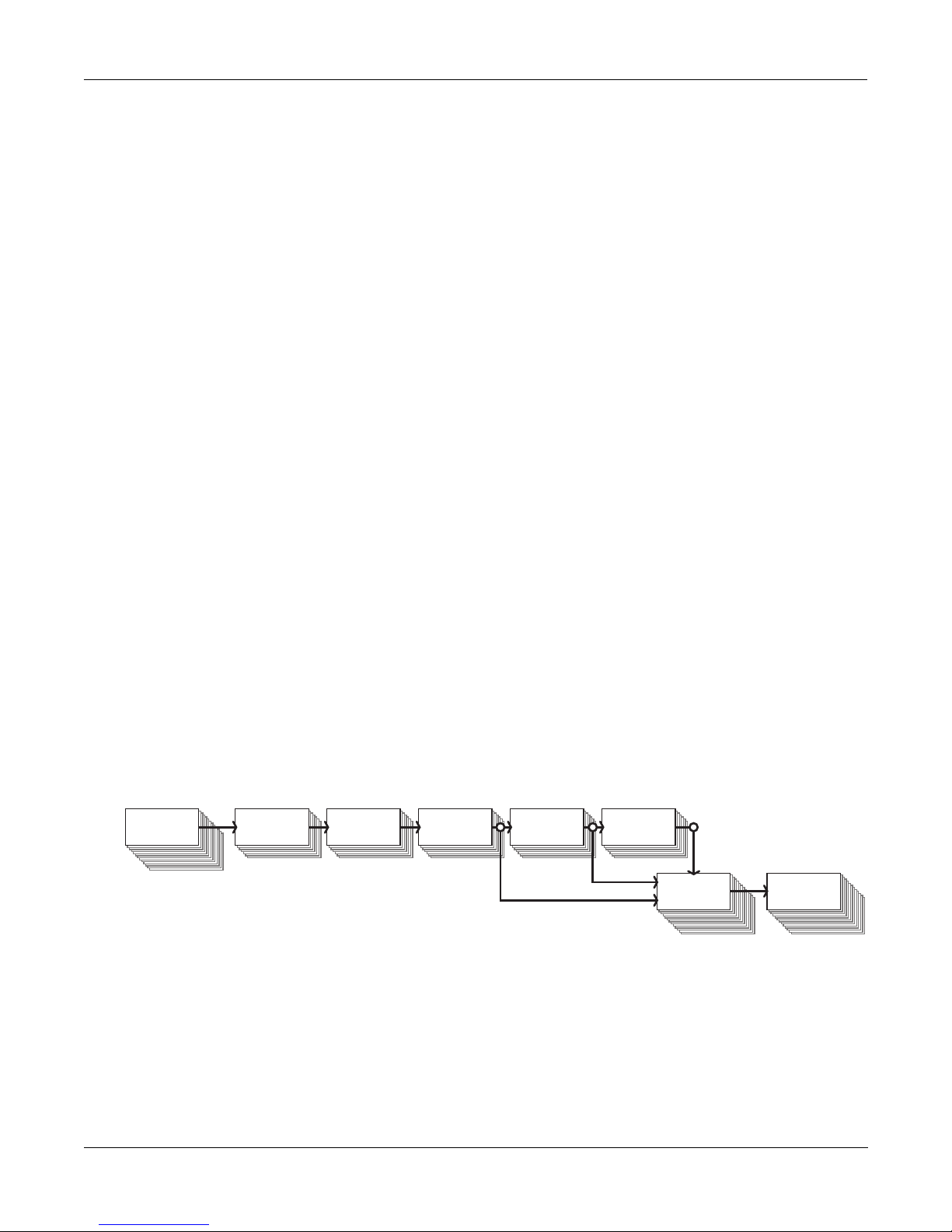
Here’s a quick look at the signal path through the KSP8. For details, see Chapter 3.
Input Select EQ Section
Figure 1-1. Signal path through the KSP8
FX Sends
FX Buses Mix Sends
& Buses
Out Select
Hard Outputs
(back panel)
Getting In and Out
Flexibility is the word when it comes to getting signals in and out of the KSP8. Four balanced/
unbalanced analog audio inputs and outputs are standard, as are an AES digital input/output
pair. With an I/O option card installed, the KSP8 is capable of handling up to 14 inputs and 14
outputs.
There’s MIDI In, Out, and Thru, a slot for a SmartMedia card, and an optional remote control
called the RSP8.
1-1
Page 14

Getting to Know Your KSP8
What It Is
Kurzweil Digital Effects (KDFX) Algorithms
The building blocks for the KSP8’s effects are the Kurzweil Digital Effects (KDFX®) algorithms
that the engineers at Kurzweil Music Systems developed for the digital effects in the K2500™
and K2600™ series synthesizers. The KSP8 gives you lots more, however, since it’s packed with
more than twice the KDFX power of the K2600.
KDFX algorithms from the K2600 are included in the KSP8, of course, augmented by even more
algorithms, including newly developed mono, stereo, and 5.1 Surround Sound algorithms. All
of the KSP8’s presets are based on these underlying algorithms. The KSP8’s algorithms are
divided into these categories:
•
Reverb
•
Delay
•
Chorus
•
Flange
•
Phaser
•
Tremolo
•
Rotary
•
Spatial
•
Distortion
•
Dynamics
•
Filters
•
Oscillators
•
Combinations
If you’d really like to dig in deep and edit algorithm parameters, we’ve provided you with
extensive documentation for each algorithm in the KSP8 Algorithm Reference Guide, which you
can download at http://www.kurzweilmusicsystems.com/ .
1-2
Page 15
KSP8 Front Panel
The KSP8 offers a familiar interface for anyone who has used Kurzweil products before. If
you’ve used a K2000™, K2500, or K2600, you will recognize the 240 x 64 pixel display, soft
buttons, edit and exit buttons, alpha wheel and other useful features. Even if you are not
familiar with other Kurzweil products, however, you will have no trouble navigating the KSP8.
Take a moment now to familiarize yourself with the KSP8’s front panel:
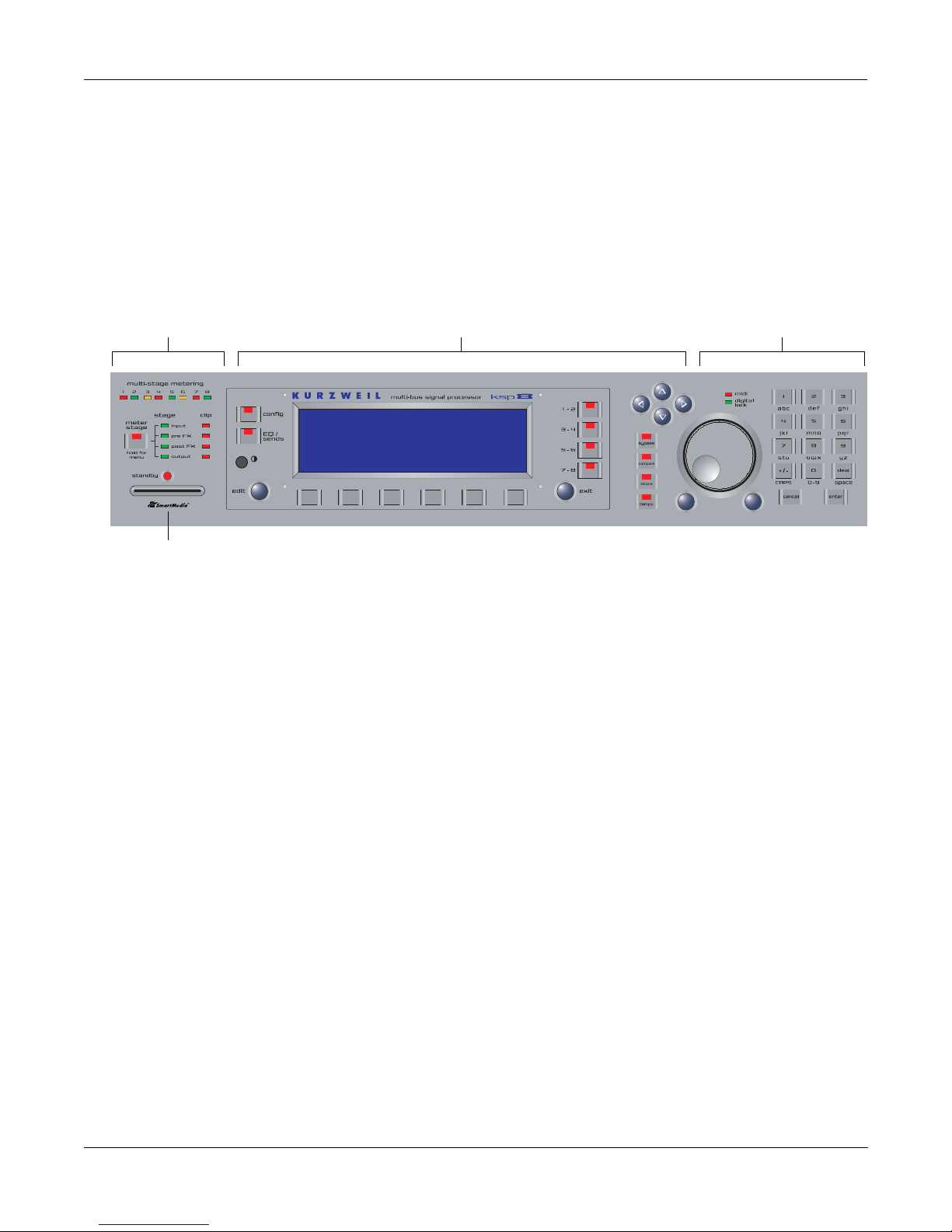
MeteringMetering Navigation Data Entry
Getting to Know Your KSP8
KSP8 Front Panel
Smart Media slot
Metering
As you can see, the front panel is clearly divided into three sections: metering, navigation, and
data entry. There’s also a slot for Smart Media memory cards that you can use for storing or
transferring your work, as well as for loading KSP8 operating system and effect object updates.
You can also update the KSP8 using MIDI.
The metering section contains eight tri-color LEDs that let you view signal levels at various
stages in the signal chain. These include:
•
input
•
pre FX
•
post FX
•
output
When you momentarily press the
meter stage button in the metering section, you select the
stage in the signal chain for which you wish to activate metering. The topmost eight LEDs
show the levels of all eight channels at a given stage. One of the green LEDs immediately to the
right of the meter stage button will light to indicate the current stage. There are also four
clipping LEDs which turn red to indicate that clipping has occurred on at least one channel at
the given stage in the signal path.
If you press and hold the meter stage button, the display screen shows horizontal bar-style
meters for all eight channels of the currently selected stage in the signal chain. Press and hold
the meter stage button a second time, or press exit , to cancel the meter display.
Standby LED
The standby LED will show you if the KSP8 is currently in standby mode. Standby mode lets
you turn off the KSP8’s display and audio output without turning off the unit. Choose Standby
from the Master page to put your KSP8 to “sleep.” Press any key on the front panel to “wake
up” the KSP8. Turning the alpha wheel does not wake up the unit, however.
1-3
Page 16
Getting to Know Your KSP8
KSP8 Front Panel
Navigation
The navigation section of the front panel consists of the display and the buttons surrounding it.
These navigation buttons will take you to every one of the KSP8’s pages and parameters.
The Display
Your primary interface with the KSP8 is its backlit graphic display. As you press various
buttons, this display reflects the commands you enter and the editing changes you make.
Contrast knob
You can adjust the KSP8 display for optimum viewing by turning the contrast knob (to the
lower left of the KSP8 display).
Pages
The KSP8’s functions and parameters are organized into smaller, related groups that appear
together in the display. You move between the various pages using the navigation buttons.
There are many pages, but there are a few features common to each page. The diagram below
shows the Studio:STUDIO page.
Studio:STUDIO|||||||||||||||||||||||||||
||||||||||||||||||#||98|Default|8|Mono||
FX1-2|||||||||||||#||99|Default|4|Stereo
FX3-4|||||||||||||#|||1|4SterIn>4SterFX|
FX5-6|||||||||||||#|||2|4MonoIn>4SterFX|
FX7-8|||||||||||||#|||3|8MonoIn>8MonoFX|
||||||||||||||||||$|||4|4StIn>4StFX->Mix
<more|MASTER|STUDIO|FXBUS||QUICK|||more>
soft buttons
The Top Line
On the top line of most pages, there’s a reminder about the current page. Many pages display
additional information in the top line, as well. The top line is almost always “reversed”—that
is, it has a white background with blue characters.
Soft Buttons
The bottom line is divided into six (sometimes fewer) sets of reversed characters that serve as
labels for the six buttons directly beneath the display. These labels—and the functions of the
buttons—change depending on the current page or mode. Consequently the buttons that select
these functions are called “soft” buttons; their functions change depending on the currently
selected page (that is, the screen currently visible on the KSP8’s display). Sometimes there are
more soft buttons available than can be displayed on one page. When this happens, buttons
labeled “more” will display on either side of the screen; press one of these soft buttons to
display additional soft buttons for the current page.
1-4
Page 17

Getting to Know Your KSP8
KSP8 Front Panel
The Config Button
The config button, to the left of the display, gives you access to the pages where you select and
set levels for your inputs and outputs. This is also where you group inputs and configure the
effects buses as stereo, mono, or surround.
The EQ/Sends Button
Press the EQ/sends button to display the EQ and Sends pages. The display will show two
channels at a time (as shown below) if you are currently in a stereo input grouping. For a
grouping such as this, you would press one of the bus select buttons (to the right of the display)
to change the pair of channels being displayed. If these channels were configured for mono or
surround sound, this display would be a little bit different, as would the function of the bus
select buttons.
Studio:INEQ||||||||||||I/O|Config=Studio
||||||||||||||||||||||||||||||||||||||||
||||||||e11111111t|errrrrrrrt|||||||||||
In|5-6--kNone||||g-kNone||||g-h|||||||||
||||||||CVVVVVVVVB|CVVVVVVVVB|||||||||||
Pad:0dB|||||||||||||||||||||||||||||||||
||||||||||||||||||||||||||||||||||||||||
IN|EQ||FXSEND|MIXSEND|||||||||||||||||||
Each KSP8 input group passes through two equalization (EQ) stages before being passed to the
effects buses. You can choose from a range of equalization options, as well as distortion, sine
and sawtooth waves, and noise generators.
The Bus Select Buttons
There are four bus select buttons to the right of the display. One or more of these will always be
lit, indicating which bus(es) is currently displayed and editable. The behavior of the bus select
buttons depends on configuration of the KSP8’s current bus: stereo, mono, or 5.1 surround.
With stereo buses, each button represents a stereo pair. If the current bus has been configured
for mono effects, pressing the lighted bus select button will toggle between adjacent mono
buses. When you configure the KSP8 for 5.1, the top three bus select buttons will light, telling
you that buses 1–6 are configured together as the six channels required to bring you surround
sound.
The complete scoop on bus select buttons is on page 3-14.
The MIDI LED
To the right of the cursor buttons is a red LED labeled MIDI. This LED will light whenever the
KSP8 receives MIDI information from a MIDI device.
The Digital Lock LED
Below the MIDI LED is an LED that indicates when the KSP8 is digitally synchronized with
another device. This LED will blink during loss of digital lock. The digital clock source is
determined by the setting of the Clock Source parameter on the Master page. See
“ClockSource” on page 10-2.
1-5
Page 18

Getting to Know Your KSP8
KSP8 Front Panel
The EDIT Button
The edit button is one of the two blue buttons diagonally beneath the KSP8’s display, and it
takes you deeper into the inner workings of the device. Pressing the edit button tells the KSP8
that you want to change some aspect of the object marked by the cursor. For example, when a
studio is selected and you press edit, you either gain access to the underlying parameters of the
algorithm(s) with the Preset editor, or else you end up on the Chain editor page, depending on
the setting of the studio’s FXBUS page. You can then select parameters (navigation) and change
their values (data entry). If the value of the selected parameter has its own editing page,
pressing the edit button will generally take you to that page.
The EXIT Button
Press the exit button (the other blue button diagonally beneath the KSP8’s display) to leave the
current editor or “back out” of an operation. If you’ve changed the value of any parameter
while in that editor, the KSP8 will ask you whether you want to save your changes before you
can leave the editor. In general, the exit button will move you back up through the KSP8’s
operating system until you are at a top level (Studio) page. If you ever find yourself lost, you
can usually press exit repeatedly until you’re back on familiar ground.
The Cursor Buttons
To the right of the display are four blue buttons arranged in a diamond fashion. These are
called the cursor buttons. They move the cursor around the currently selected page, in the
direction indicated by their labels. The cursor is a highlighted (reversed) rectangle, or in some
cases an underscore. It marks the value of the currently selected parameter.
Programming the KSP8 involves selecting various parameters and changing their values.
Parameters are selected by highlighting their values with the cursor. The highlighted value can
be changed with any of the data entry methods described in the data entry section below.
1-6
Page 19

Data Entry
The data entry section of the front panel includes the bypass, compare, store, and tempo
buttons, as well as the Alpha wheel, the Plus/Minus buttons, and the 14-button alphanumeric
pad.
The Alpha Wheel
The Alpha Wheel is especially useful because it can quickly enter large or small changes in
value. If you turn the Alpha Wheel one click to the right, you’ll increase the value of the
currently selected parameter by one increment. One click to the left decreases the value by one
increment. If you turn it rapidly, you’ll jump by several increments.
The Plus/Minus Buttons
These buttons are located just under the Alpha Wheel, and are sometimes referred to as the
increment/decrement buttons. The Plus button increases the value of the currently selected
parameter by one, and the Minus button decreases it by one. These buttons are most useful
when you’re scrolling through a short list of values, or when you want to be sure you’re
changing the value by one increment at a time. One press of the Plus or Minus button
corresponds to one click to the right or left with the Alpha Wheel. These buttons will repeat if
pressed and held.
Getting to Know Your KSP8
KSP8 Front Panel
Pressing the Plus and Minus buttons simultaneously jumps through the current list of values in
large chunks instead of one by one. For example, each time you press the Plus and Minus
buttons together while you’re scrolling through the preset list you will fast forward to the part
of the list where a new category starts. Similarly, when scrolling through the available values
for a parameter, the Plus/Minus double-press will move you through the list in large, logical
increments (groups of ten, for example). Don’t confuse these buttons with the +/- button on the
alphanumeric pad; that button is used primarily for entering negative numeric values and
switching from uppercase to lowercase letters (and vice versa).
The Alphanumeric Pad
As its name implies, this set of 14 buttons lets you enter numeric values, and to enter names
one character at a time. Depending on where you are, the KSP8 automatically enters letters or
numerals as appropriate (you don’t have to select between alphabetic or numeric entry).
When you’re entering numeric values, press the corresponding numeric buttons, ignoring
decimal places if any (to enter 1.16, for example, press 1, 1, 6, ENTER). The display will reflect
your entries, but the value won’t actually change until you press ENTER. Before pressing
ENTER, you can return to the original value by pressing CANCEL. Pressing CLEAR is the
same as pressing 0 without pressing ENTER.
When entering names, you’ll use the left/right cursor buttons or the >>End soft button to
move the cursor to the character you want to change. Use the labels under the alphanumeric
buttons as a guide to character entry. Press the corresponding button one or more times to
insert the desired character above the cursor. The cancel button is equivalent to the right cursor
button, and enter is the same as OK. The clear button replaces the currently selected character
with a space. The “+/-” button toggles between uppercase and lowercase letters.
The alphanumeric pad also provides a nifty search function that’s described along with other
useful shortcuts on page 5-3.
1-7
Page 20

Getting to Know Your KSP8
KSP8 Front Panel
The Bypass Button
The bypass button lets you bypass the entire KSP8 from your signal chain, or individually
bypass selected effects, EQs, or sends (to mute audio going to a bus). It’s described on page 5-11
of this manual.
The Compare Button
Use the compare button to listen to the difference between the current sound of an object that
you have been editing (e.g., a preset) and the sound of the previously saved version of that
object (i.e., how it sounded before you started the current editing session).
The Store Button
Whenever you make changes to an object, you’ll notice that the store button lights. If you are
happy with the changes you’ve made to the object and you want to save it, press store. A dialog
will display that allows you to name and store the object; other options will be available, too.
If you do not want to save the changes you’ve made to an object, press exit, then press no.
The Tempo Button
Press the tempo button to enter a page where you can tap in a tempo for use with tempo-based
effects such as delays or tremolos. Press the tap soft button at least four times at the speed you
wish to set. The KSP8 will calculate the tempo you have entered and will show the tempo in
beats per minute on the display. Press the exit button to leave this page.
Only presets made with algorithms that have a Tempo parameter can sync to System tempo.
These are often marked with the label “BPM”, for “beats per minute”. Presets or algorithms
marked “ms”, for “milliseconds” are strictly based on the specified time, and will not change
with the System tempo.
Finally, the Tempo parameter of a preset must be set to System, rather than a specific tempo, for
this to work. You can set this inside a preset, or set it with a Quick or MOD.
1-8
Page 21
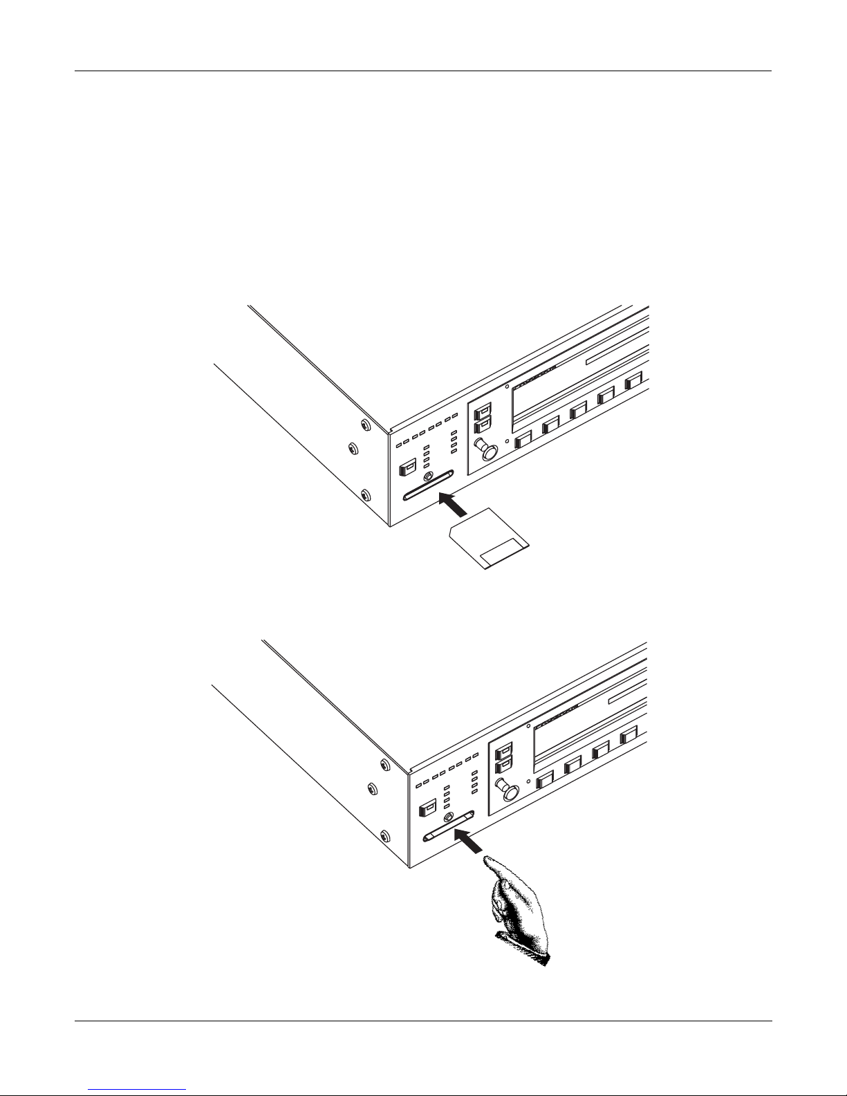
SmartMedia Card Slot
You can use 3.3v SmartMedia memory cards, in a variety of size configurations, to store and
transfer data to or from your KSP8. The cards are inexpensive and are available from a variety
of vendors. The SmartMedia card slot uses a built-in spring-loaded mechanism that makes it
easy to insert and remove cards.
To use a card, simply insert the notched end into the KSP8’s SmartMedia slot, making sure that
the side of the card with the gold plating is towards the bottom, and the notch is towards the
right, as shown in the picture below. The SmartMedia logo underneath the slot also has a small
image of a card with the notch correctly oriented to remind you of the correct way to insert it.
Getting to Know Your KSP8
KSP8 Front Panel
Note the orientation
of the notch on the card
To eject a card, push it in slightly and it will pop out:
Press the CARD soft button on the Master page to access SmartMedia card functions. See
Chapter 10 for complete information.
1-9
Page 22
Getting to Know Your KSP8
KSP8 Rear Panel
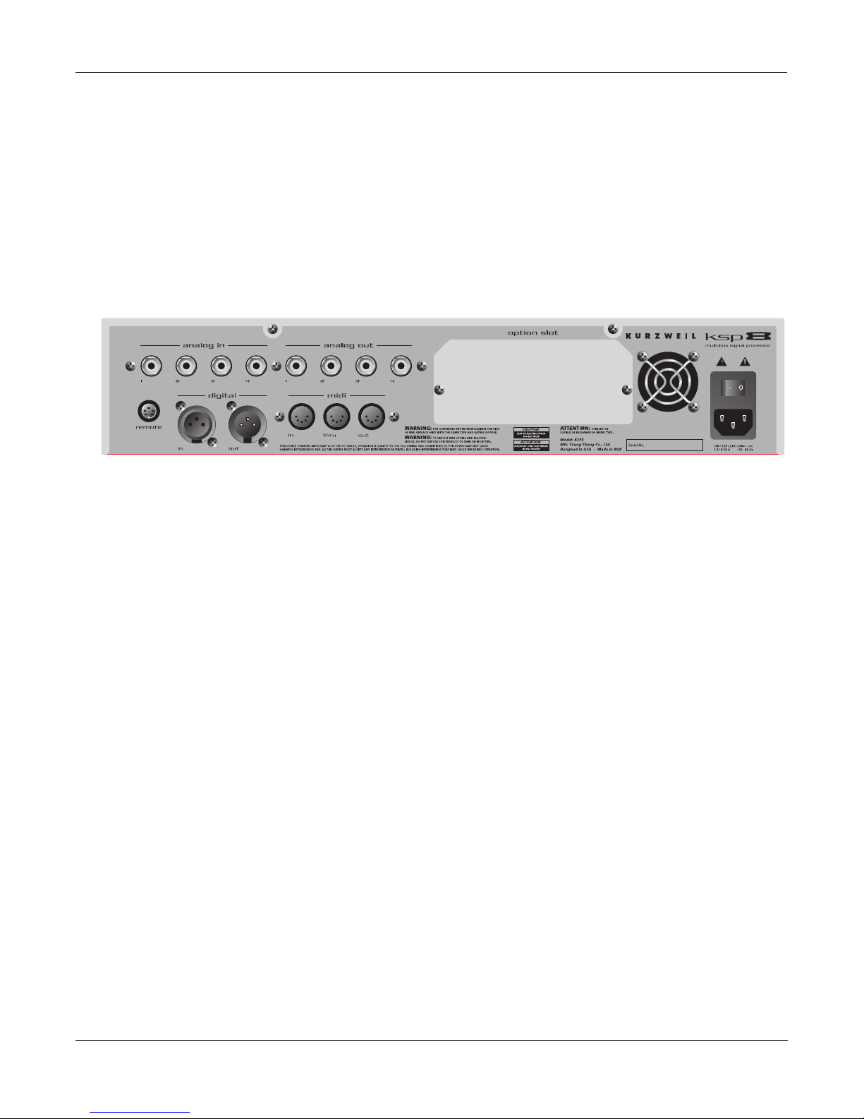
KSP8 Rear Panel
From both a hardware and a software point-of-view, the KSP8 is incredibly flexible. You can
choose from the standard analog and digital I/O offerings or add one of the available option
cards to customize the KSP8 to your liking. Throughout this manual, we’ll refer to the back
panel input and output jacks as “hard” inputs and outputs, to distinguish them from the “soft”
inputs and outputs on the KSP8’s internal buses.
Take a look at the rear panel of the KSP8 to see where the KSP8 hooks up with the other gear in
your rig:
Analog I/O
These are balanced (tip-ring-sleeve) connectors. You can add more with the Analog I/O option.
Digital I/O
These are XLR connectors; they function in either pro (AES/EBU) or consumer (S/PDIF) mode.
MIDI In, Out, Thru
MIDI In lets the KSP8 receive and slave to a sequencer. MIDI In also enables real-time control of
the KSP8 through devices such as MIDI slider and pedal boxes.
Use MIDI Out for SysEx dumps and for generating a MIDI master clock with the KSP8.
MIDI Thru duplicates whatever is received on the MIDI In port without altering it in any way.
Remote
This is where you connect either the RSP8 remote or the HUB7 multi-port hub. The RSP8
provides most KSP8 front panel functions, as well as a joystick and eight knobs for adjusting
quick parameters on the fly. The HUB7 enables you to use a single RSP8 to control up to seven
KSP8s; it also serves as a repeater, allowing you to extend the cable distance between the KSP8
and the RSP8.
Power Connection
Connect one end of the power cable provided with your KSP8 to the power connector on the
back panel of the unit; connect the other end to a power source. The type of cable provided will
depend on the country in which you’ve purchased your KSP8.
This is also the location of the on/off switch: press the “1” side of the switch to turn the KSP8
on; press the “0” side to turn the KSP8 off. For your convenience, the KSP8 also provides a
“standby” mode that you can access from the MASTER page.
1-10
Page 23
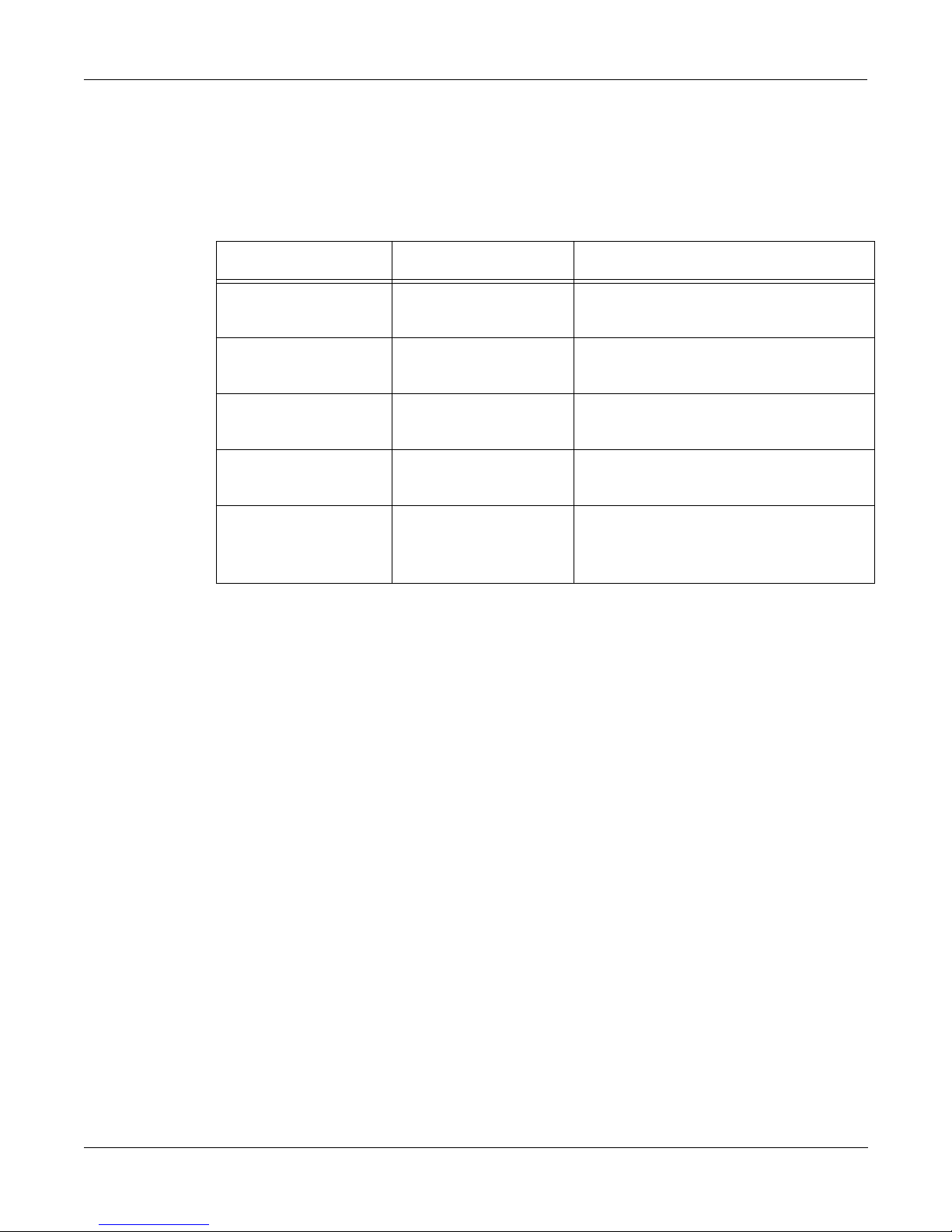
KSP8 Option Boards
To fully realize the KSP8’s eight-channel I/O capabilities, you’ll want to add one of the option
boards. The KSP8 options include:
I/O Option Name Channels Added Comments
Getting to Know Your KSP8
KSP8 Option Boards
Analog In/Out 4 channels in /
4 channels out
Increases analog capacity to 8 I/O
channels.
ADAT® In/Out 8 channels Allows the connection of products
using the ADAT optical standard.
AES In/Out 8 channels Allows the connection of products
using the AES/EBU digital standard.
TDIF In/Out 8 channels Allows the connection of products
using the TDIF standard.
KDS In/Out 8 channels Kurzweil Digital Stream - allows
direct connection with digitally
equipped Kurzweil instruments.
These options are user-installable, but they are NOT hot-swappable, so it is important that you
turn off the KSP8 (standby mode won’t be sufficient) if you are installing an option board.
Carefully follow the installation instructions provided with each option before you attempt any
work on your KSP8.
1-11
Page 24
Getting to Know Your KSP8
Basic Operations
Basic Operations
You will undoubtedly want to spend time experimenting with your KSP8. This section gives
you basic setup information. If you simply can’t wait to hear what the KSP8 can do, we’ve also
included a section called “Getting Started Really Quickly” on page 2-1.
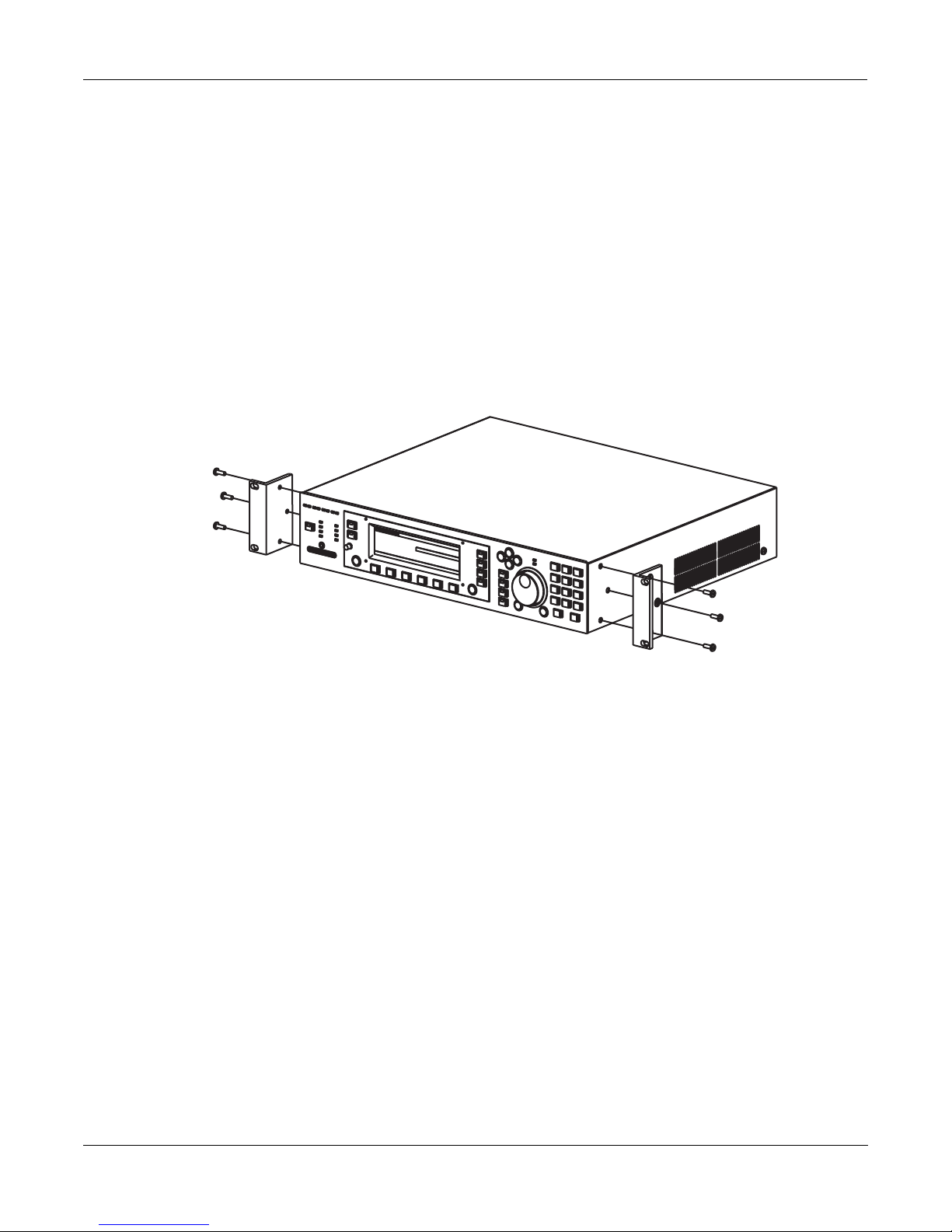
Setting Up the KSP8
1. Remove the KSP8 from its shipping box and carefully set aside the packing materials.
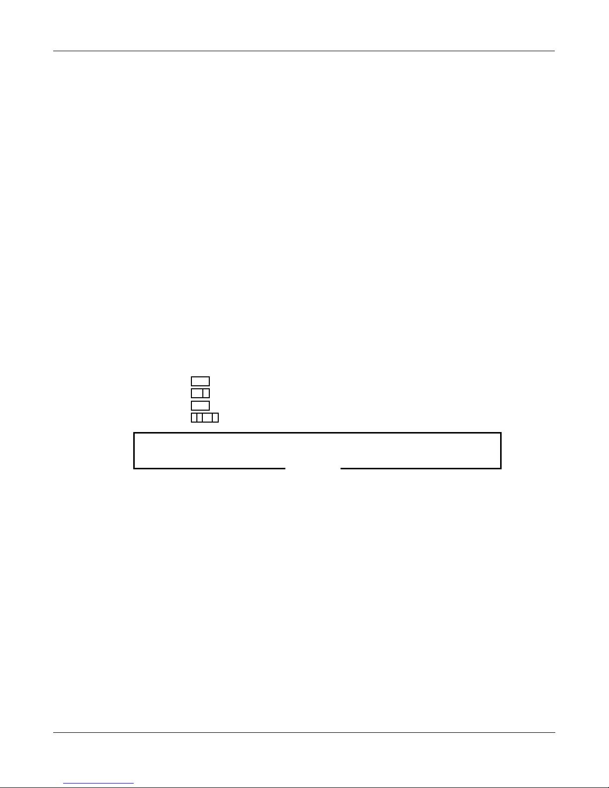
2. Install the unit into two spaces of a standard 19 inch rack using the supplied hardware to attach
the “rack ears,” as shown below:
Or, set the KSP8 on a convenient flat work space. If you will be doing this, attach the four
supplied adhesive-backed rubber feet to the bottom of the unit. Locate the rubber feet next to
the four sets of small double holes on the bottom of the unit.
3. Make audio connections between the KSP8 and your other gear.
4. Make MIDI connections (if any) from the KSP8 to your other gear.
5. Use the supplied power cable to connect the power connector on the back panel of the KSP8 to
an AC power supply.
6. Turn on the KSP8 by pressing the “1” side of the power switch on the back of the unit.
The KSP8 will display the Studio:STUDIO page. If necessary, you should adjust the screen
contrast with the contrast knob at this time.
1-12
Page 25

Studio: STUDIO Page
The first time you start up your KSP8 it displays the Studio:STUDIO page. In future sessions,
your KSP8 will remember if you were last on the Studio:STUDIO, FXBus or Quick mode page,
and will start up displaying the one of those pages that you were on most recently. You can
always get to the Studio:STUDIO page, however, by pressing the STUDIO soft button, or by
repeatedly pressing the exit button on the front panel to page back through the operating
system.
Studio:STUDIO|||||||||||||||||||||||||||
||||||||||||||||||#||98|Default|8|Mono||
Studio
Information
Display (SID)
FX1-2|||||||||||||#||99|Default|4|Stereo
FX3-4|||||||||||||#|||1|4SterIn>4SterFX|
FX5-6|||||||||||||#|||2|4MonoIn>4SterFX|
FX7-8|||||||||||||#|||3|8MonoIn>8MonoFX|
||||||||||||||||||$|||4|4StIn>4StFX->Mix
<more|MASTER|STUDIO|FXBUS||QUICK|||more>
The highest level object in a KSP8 is called the studio. The Studio:STUDIO Page shows all of the
KSP8 studios, including the ones provided with the KSP8 and any studios you may have
created. The Studio Information Display (SID) on the left side of the screen show how much of
the KSP8’s processing power is being used on each bus (you can read more about these on page
3-10).
Getting to Know Your KSP8
Basic Operations
Turn the alpha wheel or press a +, -, or cursor button to scroll through the studio list. Notice the
soft buttons on the bottom line of the display; press the front panel button beneath one of the
more> soft buttons to see the other soft buttons available from this page. A useful fact to bear in
mind is that when a soft button label is all capital letters that means that it takes you to another
page (rather than immediately performing a function).
Now look for the soft button labeled MASTER. (You may need to press one of the more>
buttons a time or two to bring this button into view.) Press the MASTER button to display the
KSP8 Master page.
Master Page
The Master page is where you set parameters that affect operation of the KSP8 at every level.
These include important things such as clock source and digital word length. Soft buttons on
the Master page give you access to the SmartMedia card page, Object page, and Util page. This
is also where you can reset the KSP8 to return it to its default state or put the unit into standby
mode.
MASTER|||||||||||||||||||||||Memory:749K
StudioChanl:|9|||||||||||||||SysEx|ID:|0
I/O|Config|:|Studio|||||||||||||||||||||
ClockSource:|48KHz|Int||||||||||||||||||
DigWordLen|:|16|Bit|||||||||||||||||||||
DitherType|:|Minimum||||||||||||||||||||
DigFormat||:|AES/EBU||||||||||||||||||||
<back|||CARD||OBJECT||UTIL|Standby|Reset
When you are on the Master page, as on any page in the KSP8, you can view and change the
parameters displayed. If you need to change one of the settings, use the cursor keys to
highlight an item, then change its value by turning the alpha wheel or pressing the + or button.
1-13
Page 26

Getting to Know Your KSP8
Basic Operations
Signal Routing
Once you’ve made all the necessary back panel connections to the KSP8, press the config button
on the front panel to access the Config pages (these are discussed in detail, starting on page 3-
11).
Studio:INSEL|||||||||||I/O|Config=Studio
||||||||||||||||||||||||||||||||||||||||
In|1:|Analog|1|||||||In|5:AES/EBU|1L||||
In|2:|Analog|2|||||||In|6:AES/EBU|1R||||
In|3:|Analog|3|||||||In|7:None||||||||||
In|4:|Analog|4|||||||In|8:None||||||||||
||||||||||||||||||||||||||||||||||||||||
INSEL||INLVL|INGRP||BUSCFG|OUTSEL|OUTLVL
Use the options on the INSEL and OUTSEL page to route signals through the KSP8.
By default, the KSP8 is set up to handle pro level signals (reference level +4 dBu). Press the
INLVL or OUTLVL soft buttons to change these levels.
Your options will be different depending on whether you are working with mono, stereo, or 5.1
surround signals. The pages displayed when you press the INGRP and BUSCFG soft buttons
let you set up the KSP8 for one of these configurations.
Syncing your KSP8 with Other Devices
When digitally synchronizing your KSP8 with other devices, either the KSP8 or another
connected device can serve as the clock master. Both 44.1 KHz and 48 KHz clock speeds are
supported, whether generated internally or externally. The KSP8 can sync to an external master
source via the AES/EBU input, or from a digital I/O option card. Each digital I/O option card
(ADAT, TDIF, AES/EBU, KDS) also includes a BNC word clock connector.
The Digital Lock LED on the front panel will light when the KSP8 is synced with another
device. The LED will blink if the lock is lost.
Processor Allocation Units (Us)
Each algorithm uses one or more Processor Allocation Units, which the KSP8 refers to simply as
“U”s. In general, the more Us an algorithm uses, the more powerful and complex the
algorithm. There are 16 Us available, and the KSP8 uses them in different quantities for
different algorithms. Depending on how many algorithms you are chaining together on
different buses, you may need to keep track of the number of Us you use. Also, it’s important to
realize that because of the way the KSP8 allocates U usage you may not be able to use all 16 Us
at once.
The documentation for each algorithm indicates the number of Us it requires.
1-14
Page 27

KSP8 Objects
As we mentioned above, the heart of the KSP8 is its collection of great sounding effects
algorithms. These are pre-loaded into the KSP8’s memory and are there for your use in studios,
chains, and presets.
The KSP8’s user interface is structured with a hierarchy of objects that (with the exception of
algorithms) you can edit and arrange for your effects needs. The illustration below shows this
basic hierarchy. If you’d like to check out lists of all the KSP8’s objects, they’re in Appendix C of
this manual.
Studio
Chain
Preset
Algorithm
Getting to Know Your KSP8
Basic Operations
you can edit and change copies of these objects.
you cannot edit algorithms
Starting at the top (since that’s how you’ll work with them), let’s take a quick look at each type
of KSP8 object:
Studio
A studio is a complete effects signal chain, from the inputs through two stages of equalization
and then on to the effects buses (where you make use of presets, chains, and algorithms –
objects that you’ll read about below) and outputs. A number of useful studios are provided
with the KSP8. You can use these as they are, edit and store them, or create your own studios
from scratch.
Chain
A chain is an object that consists of a number of presets (described below), quick parameters,
and MODs in a row. A chain can contain up to eight presets per effects bus. Refer to Chapter 7
for information on using chains.
Preset
Although you can’t change the algorithms stored in ROM, you can change the values of an
algorithm’s parameters and store that as a preset. A preset, then, is an algorithm, plus the
settings of the parameters associated with that algorithm. You can place a preset alone on a bus
in a studio, or use a series of presets in a chain. Refer to Chapter 6 for information on using
presets.
Algorithm
An algorithm is a specific type of signal processing, like a reverb, distortion, or flanger. These
are stored in ROM, and you cannot change them. You can change the values of an algorithm’s
parameters, however, and store them in a preset. The KSP8 is loaded with a few hundred
algorithms, and each one requires quite a bit of explaining – so much so, in fact, that the
algorithms have their own book, the KSP8 Algorithm Reference Guide which you can download
from the Kurzweil Music Systems web site.
1-15
Page 28
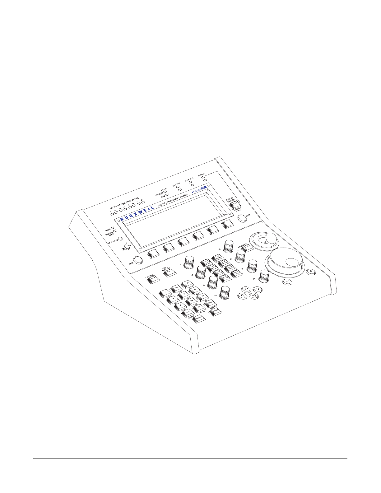
Getting to Know Your KSP8
Real-time Control of your KSP8
Real-time Control of your KSP8
You can control your KSP8 in real-time with the RSP8 remote option or use any MIDI controller
to access Quick parameters and MODs.
RSP8
The optional RSP8 remote has all the displays and controls from the front panel of the KSP8, as
well as eight dedicated knobs for fast access to Quick parameters. The RSP8 also has a joystick,
but it’s not a toy (at least as far as the IRS and your spouse are concerned). With the HUB7
multi-port hub/repeater, you can use one of these babies to control up to seven KSP8s. Yow.
Quick Parameters
Press the QUICK soft button to use “quick parameters,” which let you edit parameter values
without having to create a new preset. There are eight user-selectable defaults. The RSP8
provides eight knobs for real-time tweaking of the quick parameters.
See page 6-3 for a full explanation of quick parameters.
Using MODs for Real-time Control
You can use Studio MODs (S MODs – described on page 5-10) to control sends and EQs and
Chain MODs (C MODs – described on page 7-3) to control effects parameters.
1-16
Page 29

Upgrading, Updating, and Maintaining your KSP8
Upgrading, Updating, and Maintaining your KSP8
Like most of the professional products from Kurzweil Music Systems, the KSP8 is designed so
that it can be updated and upgraded in the future. These procedures are described in this
section, as well as information about your KSP8’s battery.
Adding Options to the KSP8
As described elsewhere, a number of option boards are available for the KSP8 to increase its
number and type of inputs and outputs. Options adding other features may also be available in
the future. In general, the KSP8’s options are user-installable. Refer to the instructions included
with each option for complete information.
Updating your KSP8’s Software
From time-to-time, Kurzweil Music Systems will release updates to the KSP8’s operating
software and soundware objects. Using the KSP8’s boot loader, you will be able to install an
update in one of the following ways:
• You can update the software or soundware from a .MID file, “playing” the data file on a
MIDI sequencer attached to the KSP8’s MIDI In port.
• You can load the software or soundware as .KOS or .KBB, or .KSP files from a SmartMedia
card.
Getting to Know Your KSP8
Refer to Appendix E for complete documentation on the KSP8’s Boot Loader.
Changing the Battery in your KSP8
CAUTION: Danger of explosion if battery is incorrectly replaced. Replace only with the same or
equivalent type.
Your KSP8 uses battery-backed memory to keep track of settings and programs. The battery is a
3 volt button type (CR 2032), and should last a long time – up to seven years, in fact. A message
on the KSP8 display at startup will indicate a low battery. Follow the instructions below to
change the KSP8 battery:
1. Back up all KSP8 data. Do this via MIDI with a SysEx dump or by saving to a SmartMedia card.
See Chapter 10 for information on these backup procedures.
2. Remove power from the KSP8
3. Turn the unit over and use a Phillips screwdriver to remove the six screws from the access
panel.
4. Locate the battery, and note the orientation of the + and - sides of the battery.
5. Remove the old battery.
6. Insert the new battery; do not use pliers, since this can short out the battery. Make sure that the
+ and - sides of the battery are oriented correctly. After installation, the + side will be visible
under the clip.
1-17
Page 30

Getting to Know Your KSP8
KSP8 Specifications
KSP8 Specifications
Dimensions
Height: 3.625 inches (92 mm)
Width: 17.125 inches (435 mm)
Depth: 15.125 inches (384 mm)
Weight: 13.25 lbs. (6 Kg)
Inputs
Analog
Four analog inputs, balanced differential using 1/4” Tip-Ring-Sleeve jacks
Input impedance: 20K ohms balanced, 10K or 20K ohms unbalanced
A/D converter: 24 bit, 128x oversampling
Maximum analog input level is +22 dBu; Minimum input level for 0 dBFS: +4dBu
Analog input level control (gain) of 0 dB to 18 dB in 1.2 dB steps, software programmable on a
per channel basis
Common Mode Rejection Ratio (CMRR): >60 dB @ ≤ 1KHz, > 40 dB @ 1 KHz – 20 KHz
Frequency response: 20 Hz - 20 KHz ± 0.15 dB
Dynamic range: > 110 dB unweighted @ 1 KHz
THD+N: <0.0015% @ 1 KHz, +19 dBu
Crosstalk: < -100 dB @ 1 KHz
Digital
Stereo AES/EBU (XLR) digital input pair
Synchronizes to AES or option card input clock or generates 48 or 44.1 kHz (all selected inputs
must be in sample rate sync)
Impedance: 110 ohms (AES) or 75 ohms (S/PDIF)
Formats: AES/EBU (AES3-1992) or S/PDIF (IEC 60958-3)
Input word length: up to 24 bits
1-18
Page 31

Outputs
Getting to Know Your KSP8
KSP8 Specifications
Analog
Four analog outputs, balanced differential using 1/4” Tip-Ring-Sleeve jacks (unbalanced TipSleeve plugs are also supported; for best results, set software for unbalanced connectors)
D/A converter: 24 bit, 128x oversampling
Output impedance: 100 ohms balanced, 50 ohms unbalanced
Maximum analog output level is +22 dBu for full-scale digital; Minimum output level for 0
dBFS: +4 dBu
Frequency response: 20 Hz - 20 KHz ± 0.15 dB
Dynamic range: > 110 dB unweighted @ 1 KHz
THD+N: <0.002% @ 1 KHz, +19 dBu
Crosstalk: < -100 dB @ 1 KHz
Digital
Stereo AES/EBU (XLR) digital output pair
Impedance: 110 ohms (AES) or 75 ohms (S/PDIF)
Formats: AES/EBU (AES3-1992) or S/PDIF (IEC 60958-3)
Output word length: 16, 20, or 24 bits
Engine
- 750K Bytes of fully static RAM battery backed
- 4M bytes of Flash ROM
MIDI
- One of each: In, Out, and Thru
Power Supply
- Universal switching supply for 90-250V, 50/60Hz
1-19
Page 32

Getting to Know Your KSP8
Stay in Touch
Stay in Touch
We’d like you to stay in touch and stay informed. Please surf on over to:
http://www.kurzweilmusicsystems.com
to keep up with all the latest from Kurzweil Music Systems, including late-breaking news, new
operating systems, and new soundware objects as they become available.
1-20
Page 33

Chapter 2
Connecting your KSP8
This chapter tells you everything you need to know about connecting your KSP8 with your
other equipment, including analog and digital audio gear and MIDI devices. For those of you
wishing to cut to the chase, however, the first part of this chapter, “Getting Started Really
Quickly” will tell you how to play with the KSP8’s multitude of effects in a matter of minutes.
Getting Started Really Quickly
We recognize that you probably want to make neat sounds and impress your friends right
away, so this section gives brief instructions to get you started now. No fancy routing will be
described here, just analog stereo in to analog stereo out (or for digital stereo in to digital stereo
out, see page 2-3). We also will assume that you have a pretty fair idea of how to hook up audio
equipment, so let’s go!
Connecting your KSP8
Getting Started Really Quickly
Analog Quick Start
1. Make sure the volume on your sound system is turned all the way down.
2. Connect your input and output cables to analog inputs 1 and 2 on the back panel; connect your
output cables to analog outputs 1 and 2.
3. Double check that the audio volume controls in your hookup are all the way down. Now, press
the switch on the back panel of the KSP8 to turn the unit on. (We are assuming that you have
taken the initiative to plug the KSP8 in already.)
The diagram below shows the Studio:STUDIO page, which will appear on the KSP8’s display
when you first power up the unit. If a different screen appears, despair not; simply press the
STUDIO soft button to bring up this screen.
Studio:STUDIO|||||||||||||||||||||||||||
||||||||||||||||||#||98|Default|8|Mono||
FX1-2|||||||||||||#||99|Default|4|Stereo
FX3-4|||||||||||||#|||1|4SterIn>4SterFX|
FX5-6|||||||||||||#|||2|4MonoIn>4SterFX|
FX7-8|||||||||||||#|||3|8MonoIn>8MonoFX|
||||||||||||||||||$|||4|4StIn>4StFX->Mix
<more|MASTER|STUDIO|FXBUS||QUICK|||more>
2-1
Page 34

Connecting your KSP8
Getting Started Really Quickly
4. Highlight “99 Default 4 Stereo” on the Studio:STUDIO page by using the alpha wheel or the +
or - keys to scroll through the list. Press the FXBUS soft button to bring up the FXBUS page:
Studio:FXBUS||||||||||||||||||||||||||||
FX1-2|||||||||||||||||||||||||||||||||||
||||||h--------------------------------h
||||||||||||||||||||||||||||||||||||||||
Type:Preset|:0|None||||||||||||||||(0U)|
||||||||||||||||||||||||||||||||||||||||
MIDICh:1||||Lock:Off||Mix|Mode:Insert|||
<more|MASTER|STUDIO|FXBUS||QUICK|||more>
5. The value of the Type parameter (that is, the text to the right of the word Type) will either be
Chain or Preset. If it is not set to this value already, highlight this field (by moving there with
left cursor button), then use the alpha wheel or + and - keys to set the type to Preset.
6. Now press the right cursor key on the front panel of the KSP8 to highlight the Preset name field
(the field to the right of the word Preset). You can now use the alpha wheel or + and - keys to
scroll through the KSP8’s different presets. Try pressing the + and - keys simultaneously to
jump between groups of different types of effects within the preset list.
Studio:FXBUS||||||||||||||||||||||||||||
FX1-2|errrrt||||||||||||||||||||||||||||
||||||kRvrbg---------------------------h
||||||CVVVVB||||||||||||||||||||||||||||
Type:Preset|:1|Small|Wood|Booth|||(2U)||
||||||||||||||||||||||||||||||||||||||||
MIDICh:1||||Lock:Off||Mix|Mode:Insert|||
<more|MASTER|STUDIO|FXBUS||QUICK|||more>
7. Finally, send an audio signal (such as the output of a CD player) to the KSP8’s input. Slowly
turn up the volume on your sound system and listen to the sounds of the KSP8’s different preset effects. We expect that this may keep you occupied for a while, but we do hope that you’ll
make time to read the rest of this manual when you’re ready to become a KSP8 power user.
2-2
Page 35

Connecting your KSP8
Getting Started Really Quickly
Digital Quick Start
1. Make sure the volume on your sound system is turned all the way down.
2. Connect your AES/EBU input to the Digital In connector on the back panel of the KSP8, and
connect another cable for AES/EBU output to the Digital Out connector.
3. Double check that the audio volume controls in your hookup are all the way down. Now, press
the switch on the back panel of the KSP8 to turn the unit on. (We are assuming that you have
taken the initiative to plug the KSP8 in already.)
The diagram below shows the Studio:STUDIO page, which will appear on the KSP8’s display
when you first power up the unit. If a different screen appears, despair not; simply press the
STUDIO soft button to bring up this screen.
Studio:STUDIO|||||||||||||||||||||||||||
||||||||||||||||||#||98|Default|8|Mono||
FX1-2|||||||||||||#||99|Default|4|Stereo
FX3-4|||||||||||||#|||1|4SterIn>4SterFX|
FX5-6|||||||||||||#|||2|4MonoIn>4SterFX|
FX7-8|||||||||||||#|||3|8MonoIn>8MonoFX|
||||||||||||||||||$|||4|4StIn>4StFX->Mix
<more|MASTER|STUDIO|FXBUS||QUICK|||more>
4. Highlight “99 Default 4 Stereo” on the Studio:STUDIO page by using the alpha wheel or the +
or - keys to scroll through the list. Press the FXBUS soft button to bring up the FXBUS page,
then press the 5-6 bus select button on the front panel of the KSP8 to display the FXBUS page
for buses 5 and 6 (which are the default buses for the KSP8’s base digital I/O).
Studio:FXBUS||||||||||||||||||||||||||||
FX5-6|||||||||||||||||||||||||||||||||||
||||||h--------------------------------h
||||||||||||||||||||||||||||||||||||||||
Type:Preset|:0|None||||||||||||||||(0U)|
||||||||||||||||||||||||||||||||||||||||
MIDICh:5||||Lock:Off||Mix|Mode:Insert|||
<more|MASTER|STUDIO|FXBUS||QUICK|||more>
5. The value of the Type parameter (that is, the text to the right of the word Type) will either be
Chain or Preset. If it is not set to this value already, highlight this field (by moving there with
left cursor button), then use the alpha wheel or + and - keys to set the type to Preset.
6. Now press the right cursor key on the front panel of the KSP8 to highlight the Preset name field
(the field to the right of the word Preset). You can now use the alpha wheel or + and - keys to
scroll through the KSP8’s different presets. Try pressing the + and - keys simultaneously to
jump between groups of different types of effects within the preset list.
2-3
Page 36

Connecting your KSP8
Getting Started Really Quickly
Studio:FXBUS||||||||||||||||||||||||||||
FX5-6|errrrt||||||||||||||||||||||||||||
||||||kRvrbg---------------------------h
||||||CVVVVB||||||||||||||||||||||||||||
Type:Preset|:1|Small|Wood|Booth||||(2U)|
||||||||||||||||||||||||||||||||||||||||
MIDICh:5||||Lock:Off||Mix|Mode:Insert|||
<more|MASTER|STUDIO|FXBUS||QUICK|||more>
7. Finally, send an audio signal (such as the output of a CD player) to the KSP8’s input. Slowly
turn up the volume on your sound system and listen to the sounds of the KSP8’s different preset effects. We expect that this may keep you occupied for a while, but we do hope that you’ll
make time to read the rest of this manual when you’re ready to become a KSP8 power user.
2-4
Page 37

Cable Connections
All cable connections to the KSP8 and its options are made on the back panel of the box. This
chapter describes the various ways that you’ll get signals and data into and out of your KSP8.
One thing to keep in mind when making your audio connections from the KSP8 is that some
presets and chains generate sounds all by themselves. Check out the chain “85 Scuba love!” for
a bubbly example of this.
Analog Connections
The KSP8 features balanced analog audio inputs and outputs via 1 / 4 -inch jacks. These inputs
and outputs, however, can be connected to either balanced or unbalanced equipment.
Although the KSP8 provides excellent unbalanced performance, you’ll get best results with
balanced connections if your other equipment provides balanced outputs and inputs.
Output
To connect the KSP8 outputs to balanced inputs, select balanced output mode on the KSP8’s
OUTLVL page (described in Chapter 3) and use balanced cables. Balanced cables should be
constructed using twisted-pair cable with 1 / 4 -inch stereo (tip-ring-sleeve) plugs on the end
that connects to the KSP8. The other end of each cable should have either 1 / 4 -inch stereo
plugs or XLR plugs to connect to balanced inputs. To connect to unbalanced inputs, select
unbalanced output mode on the KSP8’s OUTLVL page and use unbalanced cables. Unbalanced
cables should be constructed using coaxial cable with 1/4 -inch mono (tip-sleeve) plugs on both
ends.
Connecting your KSP8
Analog Connections
Input
To connect the KSP8 inputs to balanced outputs, use balanced cables as described above. To
connect to unbalanced outputs, use unbalanced cables. No selections are required on the KSP8
to select balanced or unbalanced operation.
Setting Levels
For best performance, set the KSP8's output level (also on the OUTLVL page) to the maximum
level that doesn't cause distortion in your system. If the output levels are set too low and must
be increased later on by adding gain (amplification), system noise will increase.
2-5
Page 38

Connecting your KSP8
Digital Connections
Digital Connections
A stock KSP8 has two AES/EBU digital connectors on the back panel: a female XLR for stereo
input and a male for stereo output.
Important: The digital connectors on a stock KSP8 are routed by default to buses 5 and 6.
Both Pro and Consumer formats (24 bit maximum) are supported, as described below.
The AES/EBU inputs and outputs can be used with S/PDIF digital audio signals (also known
as “CP-340 Type II” and “AES Consumer” formats). S/PDIF signals use single-conductor
shielded video cable, terminated in RCA (phono-type) jacks. (They can also use optical fiber
cables.) There are differences between AES/EBU and S/PDIF involving signal level, line
impedance, and channel status data. The circuits used at the KSP8’s digital inputs are sensitive
and tolerant enough to accept either kind of signal.
You can easily make an adaptor to bring S/PDIF signals into the KSP8’s AES/ EBU inputs. The
shield of the RCA connector is wired to pins 1 and 3 of the XLR connector, and the center (hot)
conductor of the RCA connector is wired to pin 2 of the XLR. Below is a diagram of such an
adaptor:
From S/PDIF Out
You can use a similar adapter to send AES/EBU signals from the KSP8 to an S/PDIF device.
Since these are not balanced cables, we recommend that you keep cable lengths to a minimum.
3
1
2
From AES Out
(solder side)
2
To AES In
To S/PDIF In
3
1
2-6
Page 39

MIDI Connections
Like most MIDI devices, the KSP8 is fitted with MIDI In, MIDI Out, and MIDI Thru connectors.
These are located on the back panel, and are 5-pin DIN connectors that will accept standard
MIDI cables.
MIDI In lets the KSP8 receive from and slave to a sequencer, and also enables real-time control
of the KSP8 from devices such as MIDI pedal or slider boxes. See Chapter 9 for information on
real-time control of the KSP8 through MIDI.
MIDI Out lets you send a SysEx dump or a KSP8-generated MIDI master clock. Information
about SysEx is included in Appendix D of this manual. Master clock information is included in
Chapter 10.
MIDI Thru duplicates whatever is received on the MIDI In port without altering it in any way.
You can see any MIDI events that the KSP8 receives by using MIDIScope, available from the
Master mode UTIL page (described in Chapter 10).
SmartMedia Cards
Connecting your KSP8
KSP8 Options
SmartMedia memory cards are available in a variety of size configurations, allowing you to
store and transfer data to or from your KSP8. The KSP8 uses 3.3v SmartMedia cards, by the
way, not the 5v variety. The 3.3v SmartMedia cards are the most common type, anyway, but
you’ll still want to check that you get the right kind when you go shopping.
The SmartMedia card slot uses a built-in spring-loaded mechanism that makes it easy to insert
and remove cards. To use a card, simply insert the notched end into the KSP8’s SmartMedia
slot, making sure that the side with the gold plating is facing towards the bottom. To eject a
card, push it in slightly until it pops out a bit allowing you to remove it.
Press the CARD soft button on the Master page to access SmartMedia functions for the KSP8.
These functions are described in Chapter 10 of this manual.
KSP8 Options
The following user-installable option boards are available for the KSP8:
• Analog In/Out
• ADAT In/Out
• AES In/Out
• TDIF In/Out
• KDS In/Out
Installation and usage documentation is provided with each option.
The following options are also available:
• RSP8 – remote control
• HUB7 – multi-port hub/repeater
2-7
Page 40

Connecting your KSP8
KSP8 Options
2-8
Page 41

Chapter 3
Configuring Your KSP8
Signal Routing in the KSP8
Before we look at the different ways you can configure your unit, let’s take a look at the path a
signal follows as it travels through the KSP8. Figure 3-1 provides an overview of the signal path
through the KSP8, as well as the patch points within a KSP8 studio.
KSP8 Studio
Pre FX
patch points
Post FX
patch points
Configuring Your KSP8
Signal Routing in the KSP8
Mix
patch points
Hard Inputs
(back panel)
Hard Inputs
Input Select EQ Section
Figure 3-1. KSP8 Studio showing signal path and patch points
FX Sends
FX Buses Mix Sends
& Buses
Out Select
Hard Outputs
(back panel)
With the exception of the physical connections made on the back panel, all of the signal routing
is defined within a studio, the KSP8’s top-level object (which we’ll get into in some detail in
Chapter 5). Signals pass through input, EQ, effects (FX sends and buses), mix (sends and
buses), and output sections, which are each discussed below.
We’ll refer to anything you plug into the back panel of the KSP8 as a “hard input.” For starters,
there are the four analog and two digital inputs on the plain vanilla KSP8. If you have one of
the KSP8 option boards (such as the digital I/O option) installed, you could have as many as
fourteen hard inputs on your KSP8.
Input Select
While you can have up to fourteen hard inputs, the KSP8’s eight bus architecture requires you
to select eight (or fewer) inputs to process. The INSEL page (described on page 3-11) is where
you’ll make this choice.
3-1
Page 42

Configuring Your KSP8
Signal Routing in the KSP8
EQ Section
You can configure up to two EQ functions (different types of equalization – a notch filter and a
parametric equalizer – perhaps) on each EQ bus. Notice that the output of the first function is
routed directly into the second function. So if you decide to configure two EQ functions the
signal will be affected by the two EQ boxes in series.
FX Sends
These are FX sends to the buses, similar to what you find on a mixing board. You can read more
about the FX sends on page 3-16.
FX Buses
The FX buses are where the actual effects processing occurs. Each bus can contain either a
preset or a chain (which can, in turn, consist of up to eight presets), so quite a bit of processing
can take place in this section. You can patch the outputs of the FX buses directly to the KSP8’s
outputs or send them on to the mix section.
Mix Buses
The mix section also has two sends. By default many studios are configured so that all your
buses are mixed to a stereo pair. This is done merely as a convenience, however, and you can
configure the mix buses any way that you wish.
Out Select
The OUTSEL page lets you select up to eight outputs. If you’ve got any of the KSP8 options
installed, however, some of the selections on the OUTSEL page may actually be wired to more
than one hard output (to a maximum total of fourteen). The chart on page 3-13 shows how this
works.
Hard Outputs
Anything you plug into the back panel of the KSP8 is called a “hard output.” If you have one of
the KSP8 option boards installed, you may have up to fourteen hard outputs available to you.
3-2
Page 43

Patch Points
The small circles in Figure 3-1 represent patch points, the places in each signal path where you
can route a signal directly to the output of the KSP8. Some patch points are also shown as little
circles on the KSP8’s display. The display below, for example, shows the MIXSEND page.
Configuring Your KSP8
Patch Points
Studio:MIXSEND||||||||||||||||(Studio)
||||||||||||||||||||||||||||||||||||||||
|||||||||||||||||||||||||||||
||||||||e1111111111t|||errrrrrrrt|||||||||||
Mix buses
FX5-6---kMix1-2|Balg-o|kNone||||g-oh||||||||
||||||||CVVVVVVVVVVB|||CVVVVVVVVB|||||||||||
|||||||||Gain|:0.0dB||||||||||||||||||
|||||||||Bal||:0%||||||||||||||||||||||||
patch points
|||||||||Width:100%||||||||
IN|EQ||FXSEND|MIXSEND||||||||||||||||||
The KSP8’s architecture provides the following patch points:
• Pre FX – after the signal passes through the EQ section, but before any actual effects
processing
• Post FX – after the signal passes through the EQ section and an FX bus
• Mix – after passing through the FX section, the signal from one or more buses can be
mixed, panned, or balanced
The OUTSEL page (described on page 3-12) is the place where you “patch” a signal to the
output section of the KSP8.
3-3
Page 44

Configuring Your KSP8
Configuration Basics
Configuration Basics
This section gives an overview of the three different ways you can configure the KSP8’s buses:
• Stereo
• Mono
• 5.1 Surround
Combining Different Bus Configurations
The flexible KSP8 architecture lets you combine differently configured buses, so that you can,
for example, configure buses 1–6 for 5.1 surround sound and leave buses 7 and 8 configured as
a stereo pair. You can also change the configuration of a bus after its signal is processed by the
EQ section. This means that if you wanted to you could EQ buses 1 and 2 as separate mono
buses, then process the pair as a stereo bus in the effects section.
The following pages will get you started with stereo, mono, and 5.1 bus configuration;
complete reference for all of the KSP8’s configuration pages is provided later in this chapter.
One more thing. The KSP8 always offers you eight internal buses for your routing pleasure. To
get eight signals in or out of the KSP8, however, (through the “hard” inputs and outputs on the
back panel, that is), you’ll need to install one of the option boards that offers additional ins and
outs. A stock KSP8 without any I/O options gives you four analog ins and outs and two for
digital. Internally, though, you will always have the flexibility of eight buses at your disposal,
and you can use the mix buses to digitally combine and output differently processed signals.
Bus Select Buttons
The bus select buttons are the four buttons directly to the right of the KSP8’s display. As you’ll
see, they function slightly differently depending on whether the current bus is configured as
stereo, mono, or 5.1.
Stereo bus
(button selects pair)
Mono bus
(button toggles
between buses)
5.1 surround bus
(button selects
buses 1–6)
3-4
Page 45

Stereo Buses
We’ll start with stereo bus configuration, since the KSP8’s eight buses are configured by default
as four adjacent stereo pairs. Stereo buses, in fact, must always be configured as adjacent pairs.
So you can configure all or some of the following pairs as stereo: 1 and 2, 3 and 4, 5 and 6, 7 and
8, but not 1 and 3, 2 and 6, or any other non-adjacent permutation. (And 2 and 3, 4 and 5, and 6
and 7 won’t cut it either, just in case you were wondering.)
The config button, located on the front panel of the KSP8 (to the left of the display), provides
access to all of your configuration screens, whether for stereo, mono, or 5.1. Press this button to
see a screen such as this one:
Studio:INLVL|||||||||||I/O|Config=Studio
||||||||||||||||||||||||||||||||||||||||
In|1:0.0dB||||||||||||||||||||||||||||||
In|2:0.0dB||||||||||||||||||||||||||||||
In|3:0.0dB||||||||||||||||||||||||||||||
In|4:0.0dB||||||||||||||||||||||||||||||
||||||||||||||||||||||||||||||||||||||||
INSEL||INLVL|INGRP||BUSCFG|OUTSEL|OUTLVL
Configuring Your KSP8
Configuration Basics
Notice the arrangement of the soft buttons at the bottom of the screen:
INSEL||INLVL|INGRP||BUSCFG|OUTSEL|OUTLVL
The arrangement of these buttons from left to right is, as we shall see, analogous to the path of
a signal through the KSP8. In conjunction with the bus select buttons (to the right of the
display), you can access input functions by pressing one of the left-side soft buttons (INSEL
and INLVL), perform internal bus configuration through the center soft buttons (INGRP and
BUSCFG), and make your output selection and output level setting with the right-side soft
buttons (OUTSEL and OUTLVL).
Pressing any one of these soft buttons will bring up the labeled page. So pressing INLVL, for
example, brings up the screen we are currently viewing.
Press the BUSCFG soft button to bring up the BUSCFG (Bus Configuration) page:
Studio:BUSCFG|||||||||||||||||||(Studio)
||||||||||||||||||||||||||||||||||||||||
FXBus1:Stereo|Left|||FXBus5:Stereo|Left|
FXBus2=Stereo|Right||FXBus6=Stereo|Right
FXBus3:Stereo|Left|||FXBus7:Stereo|Left|
FXBus4=Stereo|Right||FXBus8=Stereo|Right
||||||||||||||||||||||||||||||||||||||||
INSEL||INLVL|INGRP||BUSCFG|OUTSEL|OUTLVL
Since the KSP8’s default configuration is four stereo pairs, your BUSCFG screen should look
like the one shown above (unless your unit’s configuration has been changed already). You can
see that stereo left and stereo right are always on adjacent pairs. Also notice that an equals sign
is inserted in place of a colon to show a bus whose configuration is dependent on another bus.
FXBus2, for example, can’t be changed to a mono bus, since FXBus1 is set to Stereo Left forcing FXBus2 the next adjacent bus to be configured as Stereo Right.
Let’s stay on the BUSCFG page and see how you can use it to configure mono buses.
3-5
Page 46

Configuring Your KSP8
Configuration Basics
Mono Buses
Any bus can be a mono bus, although you may be constrained by the configuration of other
KSP8 buses. For example, as shown in the Stereo buses example above, if you configure FXBus1
as a Stereo Left bus, the KSP8 makes darn sure that FXBus2 is a Stereo Right bus. That’s simply
how the KSP8 architecture is designed to work.
Now, starting with the same BUSCFG screen used in the Stereo buses example (press Config >
BUSCFG to get back there, if necessary), highlight the setting of FXBus1 then turn the alpha
wheel one click to the left. The screen should look like this:
Studio:BUSCFG|||||||||||||||||||(Studio)
||||||||||||||||||||||||||||||||||||||||
FXBus1:Mono||||||||||FXBus5:Stereo|Left|
FXBus2=Mono||||||||||FXBus6=Stereo|Right
FXBus3:Stereo|Left|||FXBus7:Stereo|Left|
FXBus4=Stereo|Right||FXBus8=Stereo|Right
||||||||||||||||||||||||||||||||||||||||
INSEL||INLVL|INGRP||BUSCFG|OUTSEL|OUTLVL
Notice how the KSP8 automatically changed FXBus2 to a mono bus too. The equals sign shows
you that the setting of this bus remains dependent on the setting of FXBus1. Try pressing any of
the four cursor keys on the front panel of the KSP8, and you’ll see that the KSP8 prevents you
from even attempting to change the setting of any of the buses punctuated with equals signs.
5.1 Surround Buses
5.1 Surround (sometimes just known as “5.1”) is quickly becoming a popular audio format,
especially in the realm of film. The “5” in 5.1 refers to the five channels that carry left, right,
center, left rear, and right rear sound. The “.1” in 5.1 is the LFE (low frequency effects) channel
that provides bass sound and rumbly stuff. Its placement in the surround spectrum is not a
concern, since bass sounds are much less directional than their high frequency relations.
The five full range channels and one low frequency channel use six of your KSP8 buses, and are
always configured as shown below:
KSP8 bus 5.1 Channel
1 Left
2 Right
3 Center
4 Low Frequency Effects (LFE)
5 Left Rear
6 Right Rear
7 not used
8 not used
3-6
Page 47

Configuring Your KSP8
Configuration Basics
Buses 7 and 8, as you can see from the above table, are not used as 5.1 buses. They are, then,
available for your use as a stereo pair or two mono buses.
To configure your KSP8 for 5.1, start at the Bus Configuration page, just as you did for stereo
and mono above. As in the previous two examples, you reach this page by pressing the config
button on the front panel of the KSP8, then pressing the BUSCFG soft button.
Use the cursor keys to highlight the setting of FXBus1, then turn the alpha wheel to the right
until the screen looks like the one shown below. Notice, too that the 1–2, 3–4, and 5–6 bus select
buttons (to the right of the display) have now lighted. This shows that you are now active in all
six buses, 1–6.
Studio:BUSCFG|||||||||||||||||||(Studio)
||||||||||||||||||||||||||||||||||||||||
FXBus1:5.1|Left||||||FXBus5=5.1|L|Rear||
FXBus2=5.1|Right|||||FXBus6=5.1|R|Rear||
FXBus3=5.1|Center||||FXBus7:Stereo|Left|
FXBus4=5.1|LFE|||||||FXBus8=Stereo|Right
||||||||||||||||||||||||||||||||||||||||
INSEL||INLVL|INGRP||BUSCFG|OUTSEL|OUTLVL
As with Stereo and Mono configurations, a colon indicates the buses whose setting you can
change, while an equals sign will appear on any bus that you can not configure independently.
In the case of 5.1, six buses are required; the KSP8 will always use buses 1–6 for a 5.1
configuration.
Panning and Surround Sound
Depending on the surround techniques you are using, the FXSEND page (described on page 3-
16) may offer specific panning options. For example, you can specify whether or not to pan
through the center channel; if this channel is reserved for dialog you may not want a signal to
pan through it.
There’s more information on surround panning options in the section, “Signal Control through
FXSENDs and MIXSENDs” on page 3-17.
3-7
Page 48

Configuring Your KSP8
Putting It All Together
Putting It All Together
Here are two possible scenarios showing how you might use the KSP8 in your studio. The first
illustration shows two stereo pairs and three mono sources being processed on three stereo and
two mono effect buses with different effects. One mono source is panned to a stereo effect bus,
and the others to mono effect buses; these are then submixed to a single stereo mixdown bus.
Mixing Board
Stereo
FX
Sends
Mono
FX
Sends
Stereo
FX
Returns
KSP8 Inputs
KSP8 Outputs
Stereo EQ
Stereo EQ
Mono EQ
Mono EQ
Mono EQ
Mono EQ
(Not Used)
Stereo FX
Sends and
Panners
Stereo FX
Sends and
Panners
Mono FX
Sends and
Panners
Mono FX
Sends and
Panners
Mono FX
Sends and
Panners
Mono FX
Sends and
Panners
(Not Used)
FX Bus 1-2
(Stereo)
Rvrb
FX Bus 3-4
(Stereo)
Flng
FX Bus 5
(Mono)
Cmpr
FX Bus 6
(Mono)
Dist
FX Bus 7-8
(Stereo)
Lvrb
Mix Bus 1-2
(Stereo)
Figure 3-2. Configuration example
3-8
Page 49

Configuring Your KSP8
Putting It All Together
The next example shows a 5.1 channel stem plus two mono sources (panned independently
from the 5.1 stem) being processed together in a 5.1 channel surround reverb.
Mixing Board
Figure 3-3. Another configuration example
5.1 FX
Send
Mono
FX
Sends
5.1 FX
Return
KSP8 Inputs
KSP8 Outputs
5.1 EQ
Mono EQ
Mono EQ
5.1 FX Send
and Panner
5.1 FX Send
and Panner
5.1 FX Send
and Panner
FX Bus 1-6
(5.1)
Rvrb
FX Bus 7-8
(Not Used)
3-9
Page 50

Configuring Your KSP8
Meet SID
Meet SID
The Studio Information Display (affectionately known in these parts as SID) occupies most of
the left side of the Studio:STUDIO page. SID shows you the size and width of the effects buses
in the current studio (that is, the studio currently highlighted in the studio list on the right side
of the Studio:STUDIO page).
Stereo Buses
The example below shows a studio with four stereo buses (that’s the width part), and the size
(in Us) of the presets on these buses. When a chain is present on an effects bus (such as buses
FX3-4 and FX7-8 in the example below), multiple boxes will show you the number and size of
the presets in the chain.
Mono Buses
The example below shows eight mono buses.
5.1 Buses
This screenshot shows six buses dedicated to 5.1 surround, as well as a stereo bus.
3-10
Page 51

Config Pages
You reach the KSP8’s configuration (Config) pages by pressing the config button on the front
panel of the unit. The first time you press this button the INSEL page will display.
Subsequently, the page you have viewed most recently will display when you press the config
button.
The INSEL (Input Select) Page
Studio:INSEL|||||||||||I/O|Config=Studio
||||||||||||||||||||||||||||||||||||||||
In|1:|Analog|1|||||||In|5:AES/EBU|1L||||
In|2:|Analog|2|||||||In|6:AES/EBU|1R||||
In|3:|Analog|3|||||||In|7:None||||||||||
In|4:|Analog|4|||||||In|8:None||||||||||
||||||||||||||||||||||||||||||||||||||||
INSEL||INLVL|INGRP||BUSCFG|OUTSEL|OUTLVL
The INSEL page is where you specify which of your hard inputs (back panel connectors, that is)
you will be processing with the KSP8. Depending on which (if any) option board you have
installed, you may have up to 14 inputs from which to choose. Alas, you can’t process all 14
hard inputs at once. You will have to make selections on this page to choose the eight inputs
that you wish to process. You can combine analog and digital inputs in any order on this page,
and you can also do funky things like assign one hard input to all eight of your input buses.
Configuring Your KSP8
Config Pages
Only hard inputs that actually exist will be shown as choices for these buses. So for a stock
KSP8 without any option boards installed, your choices will be Analog 1–4, AES/EBU 1L and
AES/EBU 1R.
The INLVL (Input Level) Page
Studio:INLVL|||||||||||I/O|Config=Studio
||||||||||||||||||||||||||||||||||||||||
In|1:0.0dB||||||||||||||||||||||||||||||
In|2:0.0dB||||||||||||||||||||||||||||||
In|3:0.0dB||||||||||||||||||||||||||||||
In|4:0.0dB||||||||||||||||||||||||||||||
||||||||||||||||||||||||||||||||||||||||
INSEL||INLVL|INGRP||BUSCFG|OUTSEL|OUTLVL
Use the INLVL page to boost the level of any analog signal coming into the KSP8.
Your digital input levels are not affected by the settings that you make on this page.
3-11
Page 52

Configuring Your KSP8
Config Pages
The INGRP (Input Group) Page
Studio:INGRP|||||||||||I/O|Config=Studio
||||||||||||||||||||||||||||||||||||||||
In|1:Stereo|Left|||||In|5:Stereo|Left|||
In|2=Stereo|Right||||In|6=Stereo|Right||
In|3:Stereo|Left|||||In|7:Stereo|Left|||
In|4=Stereo|Right||||In|8=Stereo|Right||
||||||||||||||||||||||||||||||||||||||||
INSEL||INLVL|INGRP||BUSCFG|OUTSEL|OUTLVL
The INGRP page groups buses as they enter the EQ section of the KSP8. Choose from stereo,
mono, or 5.1 surround options. An equals sign indicates that a bus is linked to one of the buses
listed above it. You can only change the setting for a bus that is shown with a colon.
The BUSCFG (Bus Configuration) Page
Studio:BUSCFG|||||||||||||||||||(Studio)
||||||||||||||||||||||||||||||||||||||||
FXBus1:Stereo|Left|||FXBus5:Stereo|Left|
FXBus2=Stereo|Right||FXBus6=Stereo|Right
FXBus3:Stereo|Left|||FXBus7:Stereo|Left|
FXBus4=Stereo|Right||FXBus8=Stereo|Right
||||||||||||||||||||||||||||||||||||||||
INSEL||INLVL|INGRP||BUSCFG|OUTSEL|OUTLVL
The BUSCFG page configures the buses after their signals have been processed by the EQ
section, but before signals are sent to the mix or output sections. Choose from stereo, mono, or
5.1 surround options. An equals sign indicates that a bus is linked to one of the buses listed
above it. You can only change the setting for a bus that is shown with a colon.
The OUTSEL (Output Select) Page
Studio:OUTSEL||||||||||I/O|Config=Studio
||||||||||||||||||||||||||||||||||||||||
Out1|:PostFX|1||||||Out5/AESL:PostFX|5||
Out2|:PostFX|2||||||Out6/AESR:PostFX|6||
Out3|:PostFX|3||||||Out7|||||:PostFX|7||
Out4|:PostFX|4||||||Out8|||||:PostFX|8||
||||||||||||||||||||||||||||||||||||||||
INSEL||INLVL|INGRP||BUSCFG|OUTSEL|OUTLVL
On the OUTSEL page you can select the patch point at which the signal on each bus is sent to a
hard output (back panel connector, in other words). The Post-FX signal on each bus is the
default for OUTSEL, however you can choose to set an output to Pre-FX or Mix.
3-12
Page 53

Configuring Your KSP8
Config Pages
Out1–Out8 are basically “hard-wired,” although the signal at each out will depend on any
options you have installed in the KSP8. Each Out on this page, in fact, may represent more than
one hard out (physical connector on the back panel) of the KSP8. If you’ve got the analog I/O
option installed for example, the signal represented by Outs 5 and 6 will be both the AES stereo
pair of the stock KSP8 and analog outs 5 and 6 (from the option card). The following chart
shows the outputs:
Out Stock KSP8 Analog I/O option ADAT option Digital I/O option
Out1 Analog 1 Analog 1 Analog 1 &
ADAT 1
Out2 Analog 2 Analog 2 Analog 2 &
ADAT 2
Out3 Analog 3 Analog 3 Analog 3 &
ADAT 3
Out4 Analog 4 Analog 4 Analog 4 &
ADAT 4
Out5 AES/EBU 1L AES/EBU 1L &
Analog 5
Out6 AES/EBU 1R AES/EBU 1R &
Analog 6
AES/EBU 1L &
ADAT 5
AES/EBU 1R &
ADAT 6
Analog 1 &
Digital 1
Analog 2 &
Digital 2
Analog 3 &
Digital 3
Analog 4 &
Digital 4
AES/EBU 1L &
Digital 5
AES/EBU 1R &
Digital 6
Out7 not available Analog 7 ADAT 7 Digital 7
Out8 not available Analog 8 ADAT 8 Digital 8
Table 3-1. KSP8 Outputs
The OUTLVL (Output Level) Page
Studio:OUTLVL||||||||||I/O|Config=Studio
Out1|:0.0dB|||||||||Out5/AESL:0.0dB|||||
Out2|:0.0dB|||||||||Out6/AESR:0.0dB|||||
Out3|:0.0dB|||||||||Out7|||||:0.0dB|||||
Out4|:0.0dB|||||||||Out8|||||:0.0dB|||||
||||||||||||||||||||||||||||||||||||||||
AnalogOutputs|:Unbalanced|-12dB|||||||||
INSEL|INLVL||INGRP||BUSCFG|OUTSEL|OUTLVL
The OUTLVL page lets you boost or attenuate signal levels at your hard outputs. This is also
the place where you can switch your analog outputs between balanced or unbalanced signals
(see “Analog Connections” on page 2-5), as well as change the levels of these outputs.
3-13
Page 54

Configuring Your KSP8
EQ/Sends Pages
EQ/Sends Pages
To display the EQ/Sends pages, press the EQ/sends button on the front panel of the KSP8. As
with the config button, when you press the EQ/sends button the page that displays is the EQ or
Send page that you have viewed most recently. As you work with your KSP8, you will discover
that there are many details such as this that optimize the KSP8’s user interface for quick editing.
The Bus Select Buttons
The EQ/Sends pages work in conjunction with the bus select buttons (the four buttons to the
right of the display, labeled 1–2, 3–4, 5–6, and 7–8). You press one of these buttons to edit or
view settings for a bus (or buses), and they also serve as visual indicators of the bus or buses
currently being viewed or edited.
As shown in the chart on page 3-4, the buttons function slightly differently, depending on the
type of bus:
For a stereo bus, each button activates its labeled stereo pair. So pressing the 3–4 bus select
button, for example, will make the current page relevant to the stereo pair on buses 3 and 4.
With mono buses, the bus select buttons toggle between the labeled buses. If buses 3 and 4 were
configured for mono, then pressing the 3–4 bus select button would bring up either bus 3 or 4;
pressing it again would bring up the other bus.
5.1 surround, since it requires 6 buses, will cause the top three bus select buttons (1–2, 3–4, and
5–6) to light; the three buttons work in concert, so pressing any one is the same as pressing any
other. Since buses 7 and 8 can still be configured as either stereo or mono, the 7–8 bus select
button will function as described in either of the above two paragraphs.
The IN EQ Page
The functions on the INEQ page allow you to change the timbre of a sound by manipulating the
amplitude of specified frequency ranges. When using these functions, you usually set one or
more reference points (cutoff or center frequency) that determine where the tone will be affected.
Input to FX section
EQ function 1 EQ function 2
3-14
Page 55

EQ Functions
Listed below are the KSP8’s EQ functions. Complete information on the EQ functions,
including lots of pretty pictures, is in Appendix A of this manual.
• None
• Lo Shelf
• Parametric
• Hi Shelf
• HiPass 2P
• HiPass 3P
• LoPass 2P
• LoPass 3P
• Reson Bass
• Wide Mid
• Bandpass
• Notch
• LoShelf/HP
• HiShelf/HP
• Mid/HP
• Notch/HP
• LoShelf/LP
• HiShelf/LP
• Mid/LP
• Notch/LP
• HP 1/LP 2
• HP 2/LP 1
• Distulator
• Shaper 1LP
• Shaper 2LP
• Sine
• Sawtooth
• Sine+Shape
• Noise
• Pinker
• Impulse
Configuring Your KSP8
EQ/Sends Pages
3-15
Page 56

Configuring Your KSP8
EQ/Sends Pages
The FXSEND Page
Press the EQ/sends button on the front panel, then the FXSEND soft button to bring up the
FXSEND page. Use this page to route signals on the KSP8’s buses from the output of the EQ
section to the buses within the effects section of the KSP8. For stereo and mono buses, the signal
can be split at this point, as shown in the following diagram:
Output from
EQ section
All six buses in a 5.1 configuration must be routed to a single effect, so there will only be one
FXSEND box displayed on the FXSEND page.
Options for 5.1 Surround Panning
The FXSEND page offers some special panning options for 5.1 surround:
• Front (Frnt) – lets you specify whether or not to pan through the center channel. In films,
• Angle – relative to the front center speaker.
• Radius (Rad) – distance from the center of the room.
To FX section buses,
FXSend
FXSend
as routed by FXSends
the center channel is often reserved for dialog, which it may not be appropriate to pan.
Choose “LCR” to pan through the center channel; choose L-R to pan from left to right,
leaving the center channel unchanged.
There’s more information on surround panning options in the section, “Signal Control through
FXSENDs and MIXSENDs” on page 3-17.
The MIXSEND Page
Press the EQ/sends button on the front panel, followed by the MIXSEND soft button to bring
up the MIXSEND page. This page is where you route signals coming out of the FX section of
the KSP8. You can use the mix buses to create a submix of various FX buses before outputting
from the KSP8. For example, studios 4, 5, and 6 (unless you’ve changed them) are configured so
that all FX buses are mixed down to Mix 1-2, and the Mix 1-2 signal shows up at hard outputs 1
and 2. You can see how this is done by looking at the MIXSEND pages and the OUTSEL page.
You can also send Stereo and Mono signals to two separate mix sends at this point, as shown
below:
Output from
FX section
All six buses in a 5.1 configuration will be processed by a single mix send on this page.
MixSend
MixSend
3-16
Page 57

Signal Control through FXSENDs and MIXSENDs
Signal Control through FXSENDs and MIXSENDs
You can think of FXSENDs and MIXSENDs as being mixer controls. They send signals from
one bus to another with a variety of level and panner controls.
You access the sends pages by pressing the EQ/sends button while at the studio editor level.
The FXSEND page controls signal level and panning of input buses onto FX buses. The
MIXSEND page controls signal level and panning of FX buses onto the output mixer buses.
Let’s consider just the FXSEND page for now. What you see will depend on how your inputs
are configured on the INGRP page (reached by pushing the config button). The available send
controls are dependent on the settings in the BUSCFG page. The MIXSENDs work like the
FXSENDs, except that for the MIXSENDS there are no panners to 5.1 output mixer buses.
FXSENDs are the real place to finely control levels being sent to the effects (as opposed to
INLVL, which should be viewed as a coarse adjustment, used when configuring your KSP8
with the rest of your system). You will be able to access different send controls depending on
whether your inputs are configured as mono, stereo or 5.1 multi-channel. You can scroll
through the available send controls by moving the cursor so the send box is highlighted then
turning the alpha wheel. You can access the sends for different buses by pressing the bus select
buttons.
Configuring Your KSP8
When set to “None”, the sends do not pass audio to any FX bus. All other send controls will
include a Gain control which sets the signal level going to the FX bus. Maximum level is 24.0
dB, and minimum is -79.0 dB – there is also an “Off” position. 0.0 dB is unity gain.
When the INGRP bus configuration is set to mono for the bus being edited, the available send
controls include mono-to-mono, mono-to-stereo and mono-to-5.1 controls. The send controls
for INGRP stereo configuration include stereo-to-stereo and stereo-to-5.1. The 5.1 multi-channel
INGRP configuration sends a 5.1 input bus to a 5.1 FX bus. For each of the input to FX bus send
configurations, there may be more than one way of controlling the signals, especially when it
comes to panning. For example, the stereo-to-stereo configuration may have a balance control
(left and right channels rise and fall opposite to each other) or a pan control (the phantom
stereo image moves across the stereo field).
When sending to a mono or stereo FX bus, two separate mono or stereo sends are available for
the input. While you can send to any two mono or stereo sends, the two sends may not have FX
bus channels in common.
Send controls which send to 5.1 channel FX buses come in two variations. The “Frnt” (front)
parameter lets you switch between “LCR” and “L-R”. When set to “LCR”, sonic images panned
to the front will pan through to the front center channel. When panning an image from left to
right, the image will begin in the left speaker, form a phantom image between the left and
center speakers, then move into the center channel only. From there the image is a phantom
between center and right before moving fully into the right speaker. When Frnt is set to “L-R”
the center channel is taken out of the equation. Panning an image from left to right will produce
a phantom image between left an right speakers with none of the sound coming from the center
channel.
The panners produce phantom images between loudspeakers when panner positions are
between channels. A phantom image is produced when adjacent loudspeakers are producing
the same sonic output. The relative position of the sonic image between loudspeakers is
determined by the relative signal strengths that each loudspeaker produces. When the signal
strengths are equal, then the phantom image should be centered between speakers. With Gain
set to 0 dB (unity gain) and any Width or Rad parameters set to 100% (defaults), the KSP8
3-17
Page 58

Configuring Your KSP8
Signal Control through FXSENDs and MIXSENDs
panner implementation sets the signal level to 0 dB when an input channel is directed directly
to an output channel (there is no phantom imaging). When there is a phantom image centered
between two loudspeakers, the signal level to both loudspeakers is the same and both channels
are reduced by 3 dB.
The panners in KSP8 are simply level controlled. Level controlled panners do not perform
particularly well at producing sonic images to the sides of a 5.1 mix (between front and
surround). There are more sophisticated techniques for image positioning such as head related
transfer functions (HRTF) which are beyond the capabilities of the KSP8 send controls and
beyond the scope of this manual.
Let’s look at each send control in detail:
INGRP Send Options for Mono Configurations
FXBus1 through FXBus8
The mono-to-mono send has only a Gain control, though you can send any mono input channel
to any mono FX bus channel.
FX1-2 Pan through FX7-8 Pan
The mono-to-stereo panner has a Pan control in addition to the Gain control. The pan control
allows you to move the mono image from the left channel to the right channel of the stereo
effects bus. The -100% setting sends the signal to the left channel only, 100% sends to the right
channel only, while 0% sends to both channels equally (center).
FX1-6 X-Y
This is one of three mono-to-5.1 send controls. The LRPan control is the familiar left to right
panner: -100% is left, 100% is right and 0% is center. When set to 0%, the centered image will be
produced by the center channel (Frnt is “LCR”) or as a phantom image between left and right
channels (Frnt is “L-R”). The FSPan moves the sonic image between front speakers and the
surround speakers. When FSPan is 0% the sound will come out the front speakers, and when
FSPan is 100% the sound will come out the surround speakers. This panner is particularly
useful for simple joystick control (from the RSP8 or other device).
FX1-6 3-Way
This mono-to-5.1 panner is similar to the FX1-6 X-Y panner. The difference is that the LRPan
control affects the front channels only while there is a separate SurLR control for left-right
panning of the surrounds. This combination of controls allows some interesting panner
movements using a single control. For example, with LRPan set to -100% (left) and SurLR set to
100% (right), moving the FSPan from 0% (front) to 100% (surround) will cause the image to
move from front left to surround right through the center of the room.
FX1-6 R-Theta
The R-Theta mono-to-5.1 panner uses distance from the center of the room (R or Rad for radius)
and an Angle relative to the front center speaker to control the sonic image location. The
distance from the center of the room (Rad) is expressed as a percentage of the distance from the
center of the room to the ring formed by the loudspeakers. The Angle is expressed in degrees of
3-18
Page 59

Signal Control through FXSENDs and MIXSENDs
a circle. A circle has 360° (degrees). The center line facing forward is defined as the 0° angle.
Positive angles are to the right and negative angles are to the left. The right speaker is located at
30°, the left speaker is at -30°, and the right and left surround speakers are at 110° and -110°
respectively. 180° and -180° are the same angle which is directly to the rear.
INGRP Send Options for Stereo Configurations
FX1-2 Bal through FX7-8 Bal
The stereo to stereo balance control raises the gain of one input channel while lowering the
other. When the Bal control is set to 100% the right input will be sent fully to the right stereo FX
bus channel while the left input channel will not be heard at all. Likewise at -100% you will
hear only the left input channel passed to the left FX bus channel, with the right channel silent.
The stereo image width can be controlled with the Width parameter. 100% is full stereo width,
so the left input is sent to the left FX bus channel while the right input is sent to the right FX bus
channel. At 0% Width, the stereo width is narrowed to mono (left and right are summed), and
the balance behaves like the mono-to-stereo panner. Negative Width settings swap the left and
right channels.
Configuring Your KSP8
FX1-2 Pan through FX7-8 Pan
The stereo-to-stereo panner moves the stereo input across the FX bus stereo field. The stereo
image is maintained but is “tilted” to the right or left. When Pan is set to 0% there is no change
to the signal, while at 100% both input signals are sent to the right channel. At 50%, what had
been hard left at the input will now be in the center, and what had been in the center at the
input will now be halfway between center and right. Negative values tilt the signal to the left.
The stereo image width can be controlled with the Width parameter. 100% is full stereo width,
so the left input is sent to the left FX bus channel while the right input is sent to the right FX bus
channel. At 0% Width, the stereo width is narrowed to mono (left and right are summed), and
the panner behaves like the mono-to-stereo panner. Negative Width settings swap the left and
right channels.
FX1-6 R-Theta
The R-Theta stereo-to-5.1 panner uses distance from the center of the room (R or Rad for
radius) and an Angle relative to the front center speaker to control the sonic image location. The
distance from the center of the room (Rad) is expressed as a percentage of the distance from the
center of the room to the ring formed by the loudspeakers. The Angle is expressed in degrees of
a circle. A circle has 360° (degrees). The center line facing forward is defined as the 0° angle.
Positive angles are to the right and negative angles are to the left. The right speaker is located at
30°, the left speaker is at -30°, and the right and left surround speakers are at 110° and -110°
respectively. 180° and -180° are the same angle which is directly to the rear. The width of the
stereo image is controlled with the Width parameter. The stereo width is also expressed as an
angle in degrees of a circle. The width angle represents the angular distance between the left
and right input channels on the 5.1 FX bus. Normal stereo has a setting of 60° (when pan Angle
is 0°) while 0° collapses the stereo input to mono. Width angles greater than 90° move the image
behind you. Negative width angles swap the left and right channels. To determine the angle at
which the right input channel will appear in the 5.1 FX bus, divide the Width setting by 2 and
add the result to the pan Angle. The angular position of the left input channel is half the Width
subtracted from the pan Angle.
3-19
Page 60

Configuring Your KSP8
Master or Studio I/O
INGRP Send Options for 5.1 Configurations
FX1-6 Levels
This 5.1-to-5.1 send has only a Gain control. The gain controls all channels including center and
the low frequency effects (LFE) channel.
FX1-6 R-Theta
The R-Theta 5.1-to-5.1 panner uses distance from the center of the room (R or Rad for radius)
and an Angle relative to the front center speaker to control the sonic image location. The
distance from the center of the room (Rad) is expressed as a percentage of the distance from the
center of the room to the ring formed by the loudspeakers. The Angle is expressed in degrees of
a circle. A circle has 360° (degrees). The center line facing forward is defined as the 0° angle.
Positive angles are to the right and negative angles are to the left. The right speaker is located at
30°, the left speaker is at -30°, and the right and left surround speakers are at 110° and -110°
respectively. 180° and -180° are the same angle which is directly to the rear. When pan Angle is
set to 0° and Rad is 100%, all input channels pass directly to their corresponding 5.1 FX bus
channels. Increasing the panning angle moves all input channels to the right relative to their
former positions. The Gain controls all channels including center and the low frequency effects
(LFE) channel, whether Frnt is set to “LCR” or “L-R”.
Master or Studio I/O
You can lock into a particular input/output configuration so that the inputs and outputs you’ve
set do not change every time you change studios. The I/O Config option on the Master page is
the place where you set this parameter. It’s described on page 10-1.
You should also keep in mind that the Master I/O Config settings are saved with your KSP8’s
Master Table. This means that if you save objects and want to load them with the same Master
I/O Config settings at a later time, then you must also save (and subsequently reload) the
Master Table.
Most of the Config and EQ/Sends pages will indicate the setting of the I/O Config option. The
two exceptions are the BUSCFG and MIXSEND pages, since the information on these pages is
always saved as part of a studio.
3-20
Page 61

Chapter 4
Multi-stage Metering
The KSP8’s metering section lets you visually check signal levels on each bus by viewing the
eight LEDs labeled 1–8, in the top left corner of the unit. Additionally, four dedicated clip LEDs
let you see in an instant if a signal is clipping anywhere on the KSP8’s buses. Furthermore,
there are graphical bar-style meters that can be shown on the display screen.
Multi-stage Metering
Selecting Meter Stages
Selecting Meter Stages
You can view signal levels at these stages in the signal chain:
• input – shows levels for all eight input buses, just after analog level controls (INLVL page)
• pre FX – shows levels on FXBuses1-8, just prior to effects section (after input EQ, panning,
& send levels)
• post FX – shows levels on FXBuses1-8, after effects processing
• output – shows levels for all eight soft output buses, after output level controls
The eight LEDs at the top of the metering section show signal levels on each bus at the stage
you’ve selected. Press the meter stage button to select the stage in the signal chain that you
want to look at. For example, if you press the meter stage button until the green LED labeled
post FX lights, then each of the LEDs numbered 1 – 8 will now show the level of the signal after
it passes through the FX section on each corresponding bus.
4-1
Page 62

Multi-stage Metering
Viewing Bar-graph Meters
How to Read the Eight Level LEDs
A level LED is green when a signal is present, will turn amber when the signal reaches its
maximum usable level, and will become red if the signal clips (i.e., reaches a level where
distortion occurs). Remember that the KSP8 is a digital device, so distorting levels is unlikely to
enhance your sound in a mellifluous way. (If you’re looking for the “warmth” of analog
distortion, however, there are some wonderful tube amp simulators in the algorithm section.)
There are four dedicated clipping LEDs to the right of the meter stage LEDs. These LEDs also
turn red to indicate clipping on any channel at the indicated stage in the signal path. These
LEDs are always active, however, so they will show clipping regardless of the stage being
metered by the eight LEDs at the top of the metering section.
Viewing Bar-graph Meters
If you press and hold the meter stage button, the display shows horizontal bar-style meters for
all eight channels of the currently selected stage in the signal chain. Press and hold the meter
stage button a second time to cancel the meter display.
Meter:INPUT|||||||||||||||||||||||||||||
-dB60403020161286420!|-dB60403020161286420!
1||||||||||||||||||||5||||||||||||||||||
2||||||||||||||||||||6||||||||||||||||||
3||||||||||||||||||||7||||||||||||||||||
4||||||||||||||||||||8||||||||||||||||||
-dB60403020161286420!|-dB60403020161286420!
||||||||||||||||||||||||||||||||||||||||
INPUT|PREFX||POSTFX|OUTPUT||PEAK||||||||
Press an INPUT, PREFX, POSTFX, or OUTPUT soft button to select the stage to meter. Press
the PEAK soft button to go to the Peak view (described below).
Peak or Meters View
The Peak/Meters soft button toggles between meter view (as shown above) and peak view,
shown below. The peak levels, given in decibels (dB), show the hottest levels reached by the
signals on each bus since the last time the peak values were reset. Press the Clear button to reset
the peak levels.
Meter:OUTPUT||||||||PEAK|Levels|||||||||
||||||||||||||||||||||||||||||||||||||||
1:||||OVER!|||||||||5:|||<-127dB||||||||
2:||||-21dB|||||||||6:|||<-127dB||||||||
3:||||-86dB|||||||||7:|||<-127dB||||||||
4:||||-85dB|||||||||8:|||<-127dB||||||||
||||||||||||||||||||||||||||||||||||||||
INPUT|PREFX||POSTFX|OUTPUT|METERS|Clear|
4-2
Page 63

Gain Staging
As stated before, you probably don't want a signal to clip at any point within the KSP8. On the
other hand, you probably do want to keep your signal level as hot as possible throughout the
signal path, to maintain the best possible signal-to-noise ratio. Using the metering section, you
can check the signal levels at various stages, and boost or cut levels as necessary.
Keeping track of gain changes as a signal moves through the various sections of the KSP8,
making sure signals are optimal (neither too soft nor too loud) is known as “gain staging.”
While the KSP8 has plenty of headroom available for most processing, you may run into
problems of digital overload (clipping) if extremely high filter resonances or large amounts of
distortion or gain are used. Most headroom problems are best dealt with as “locally” as
possible; rather than just turning down a device's output to reduce clipping, you're better off
adjusting the gain at the point in the path where the level gets out of control. If the send from
the input section to the effects section is too high, adjust the send, not the input level; if a
particular chain or preset is clipping in the effects section, adjust the Out Gain of the preset (or
the Out Gain of the last preset in the chain) with a Quick Parameter or a Mod, or even within
the preset object itself. Factory presets and chains have been adjusted so that the level is
roughly the same whether the effect is active or bypassed. This is a good rule to follow in your
own work as well, to help avoid unpleasant surprises.
Multi-stage Metering
Gain Staging
Generally, you'll want each bus's signal to be hot enough that the level LEDs shine mostly
green, with some flashes of amber on transient sounds. If the LED is mostly off, with flashes of
green, then your signal is probably too soft. In the case of dense or overall loud material, the
LED may appear mostly amber, with flashes of green. This is OK, but remember that the more
amber than green, the less headroom you will have to work with before clipping occurs.
Clipping, of course, is indicated by red level LEDs and a corresponding warning from the red
clip LEDs.
4-3
Page 64

Multi-stage Metering
How to Find and Fix Clipping
How to Find and Fix Clipping
At some point, whether caused by a very hot input signal or some process inside the KSP8, you
will probably run into some unwanted digital clipping. In this case, you'll need to identify
which channels are overloading, and find a good place in the signal path to reduce the gain. To
identify an overloaded channel, press the meter stage button until the selected stage matches
the stage indicated as clipping by the clip LED. If more than one clip LED is lit, select the
earliest stage; sometimes an overload early in the signal path will cause clipping all the way
down the line. Now look to the eight level LEDs to see which channel(s) flashes red with the
clip LED.
For example, if the input clip LED is lighting, press the meter stage button until the green LED
labeled “input” is lit, then look up to the eight level LEDs; if LEDs 1 and 2 are flashing red with
the input clip LED, then you know that the clipping is occurring on input buses 1 and 2. This
means that the signal routed to inputs 1 and 2 is either too loud coming from your mixer or
external device, or the input level (INLVL) in the KSP8 is set too high.
The following chart will help you learn how to track down clipping:
If this clip LED lights: Adjust the signal level here:
input
pre FX
post FX
output
output level of device going into KSP8
or
Config>INLVL (Press config button, then INLVL soft button;
select the appropriate input and adjust the level
EQ/sends>FXSEND (Press EQ/sends button, then FXSEND
soft button; adjust the Gain for the relevant send)
or
EQ/sends>INEQ (Press EQ/sends button, then INEQ soft
button; adjust Pad setting or Gain in either processing block)
Out Gain parameter of the preset on the bus, or the Out Gain
parameter of the LAST preset in a chain on the bus. You can
adjust this parameter from multiple places: the
Studio:QUICK page, the Chain:QUICK page, as a Chain
MOD, or within a preset by pressing edit and locating the
Out Gain parameter, which is usually found on the PARAM1
page of a preset.
Config>OUTLVL (Press config button, then OUTLVL soft
button; select the appropriate output and adjust the level.
)
)
4-4
If you are using a Mixdown bus, and are getting clipping
from an output set to Mix, you may need to attenuate the gain
on the EQ/sends>MIXSEND page (Press EQ/sends button,
then MIXSEND; adjust the Gain for any relevant sends)
Page 65

Distortion Between Meter Stages
Sometimes you may encounter some distortion without seeing the clip LEDs light. This may
simply mean that you are overdriving some stage, but have not reached full-scale clipping.
Scan the four stages using the meter stage button, watching the level LEDs for predominantly
amber LEDs, and you may discover the source of the distortion.
Another possibility is that you are clipping or overdriving a signal between the meter points.
One place this could occur would be in the EQ section, where you can crank a signal up in the
first EQ block, then turn it down in the second block, or at the send; in this case neither the
input nor the pre FX clip LEDs would light because although the distortion occurs within the
EQ section, the signal is attenuated down to a nominal level by the time it reaches the pre FX
metering point.
Perhaps the most common case where this kind of distortion might occur is between the
multiple presets of a chain. As in the EQ section, it is possible to boost a signal in a preset in one
box of a chain, then cut the signal in the next box, or any later box of the chain.
There are no meter points between the individual boxes of a chain, so as long as the signal is
not clipping as it passes out of the last box of the chain, the post FX clip LED will not light. In
general you should try to maintain a reasonable level throughout the boxes in your chain, using
the Out Gain parameter which shows up in nearly every effect algorithm in the KSP8. Of
course, how you choose to construct your own chains is a matter of taste, intention, and need; if
you intend to overdrive the signal at one point and cut the gain later, that's perfectly viable and
perhaps even necessary for your specific application.
Multi-stage Metering
How to Find and Fix Clipping
4-5
Page 66

Multi-stage Metering
How to Find and Fix Clipping
4-6
Page 67

Chapter 5
Working with KSP8 Objects
Types of Objects
The KSP8’s user interface is structured with a hierarchy of objects that (with the exception of
algorithms) you can edit and arrange for your effects needs. The hierarchy of KSP8 objects
looks like this:
Studio
Working with KSP8 Objects
Types of Objects
Chain
Preset
Algorithm
Here is a brief description of each type of KSP8 object:
originals stored in ROM,
user-edited copies stored in RAM
stored in ROM (not editable)
Studio
A studio is a complete effects signal path, from the inputs through two stages of equalization
and then on to the effects algorithms and outputs. A number of useful studios are provided
with the KSP8. You can use these as they are, edit and store them, or create your own studios
from scratch. Figure 3-1 on page 3-1 shows the parts of a studio.
Effects (by which we mean presets and/or chains) are placed on the buses of a studio.
If your working environment doesn’t change much from session to session, you may find it
convenient to use a single studio that has inputs and outputs, as well as room equalization predefined. In this case, you may not need to create and save studios other than the one that works
for your standard configuration.
On the other hand, the studio object offers a convenient way to store all KSP8 settings from a
recording or performance session for future use. The important thing to know is that the KSP8’s
flexibility lets you use what works best for each situation.
Chain
A chain is an object that consists of a number of presets (described below), quick parameters,
and MODs in a row. A chain can contain up to eight presets per effects bus. Refer to Chapter 7
for information on using chains. Chains and presets can sit side-by-side on different buses in
the same studio.
5-1
Page 68

Working with KSP8 Objects
Object Type and ID
Preset
Although you can’t change the algorithms stored in ROM, you can change the values of an
algorithm’s parameters and store that as a preset. The preset object is the most basic editable
effect object in the KSP8. Each KSP8 preset is based on one algorithm (described below), and
contains values for all the parameters of that algorithm. You may place a preset directly on an
effects bus in a studio, or construct a chain of multiple presets. Refer to Chapter 6 for
information on using presets.
Algorithm
An algorithm is a specific type of signal processing, like a reverb, distortion, or flanger. These
are stored in ROM, and cannot be changed, although values of an algorithm’s parameters (and
there can be up to 92 of them!) can be changed and stored in a preset. Refer to the KSP8
Algorithm Reference Guide (provided electronically) for complete information on algorithms and
their parameters.
Object Type and ID
The KSP8 stores its objects using a system of ID numbers that are generally organized into
banks of 100. Each object is identified by its object type and object ID; these make it unique. An
object’s type is simply the kind of object it is, whether it’s a studio, preset, chain, or algorithm.
The object ID is a number from 1 to 999 that distinguishes each object from other objects of the
same type. For example, within the 200s bank, you can have a studio, a preset, and a chain, all
with ID 201; their object types distinguish them. You can’t, however, have two presets with ID
201.
When you save objects that you’ve edited, the KSP8 will ask you to assign an ID. If the original
object was a ROM object (i.e., one of the factory-supplied objects in the KSP8), the KSP8 will
suggest the first available ID. If the original object was a RAM object (i.e., one that you’ve
previously created), you’ll have the option of saving to an unused ID, or replacing the original
object.
Objects of different types can have the same ID, but objects of the same type must have
different IDs to be kept separate. When you’re saving an object that you’ve edited, you can
assign the same ID to an existing object of the same type, but if you do, the new one will be
written over the old one. For example, if you assign an ID of 1 to a preset you’ve edited, the
KSP8 will ask you if you want to “replace” the ROM preset currently stored with that ID. We’ll
discuss this further in “Saving and Naming,” later in this chapter.
The object type and ID enable you to store hundreds of objects without losing track of them,
and also to load files from disk without having to replace files you’ve already loaded.
5-2
Page 69

Shortcuts
Numeric Entry
Working with KSP8 Objects
Shortcuts
As you work with your KSP8, you will soon see how the interface is optimized for quick
editing. For example, between power cycles the KSP8 will remember whether you were on a
Studio, FXBus, or Quick page. When you restart the unit, it will bring up the page you
displayed most recently.
The paragraphs below describe the KSP8’s other shortcuts.
Any time you are choosing from a list of options, for example, the list of EQ functions available
for each box on the INEQ page, you can quickly move to a choice using numeric entry. Each
available option for the highlighted box or parameter (e.g., an EQ function box on the INEQ
page) has a numeric value associated with it. Simply type that number on the alphanumeric
pad (e.g., 2 for Parametric EQ), then press enter. Of course, the cursor must be located on the
correct field for this to work. In the case of an EQ function box, this means that your intended
box appears in reverse video on the KSP8’s display; if this is not so, then press the cursor keys
until it is.
In addition to the numbers for all of the KSP8’s soundware objects listed in Appendix C, there
are reference charts for other numeric entry shortcuts in Appendix G of this manual.
Quick Stops
When you are scrolling through lists of objects – presets, for example – simultaneously press
the plus (+) and minus (-) keys (just below the alpha wheel) to move to the next quick stop
within the list. Here’s an example: If you were currently scrolling through the chorus effects,
then pressing plus and minus simultaneously would take you to the part of the list where the
flange effects begin. This would be quicker than scrolling through the list of chori. Double-press
+ and - again to jump to the quick stop for the next type of effects in the list (phasers).
The KSP8 has been programmed with a number of other logical quick stops. It never hurts to
try the plus and minus double press to move through lists of objects.
Double and Triple Button Presses
These are a few “hidden” multiple-button presses that can speed up your work from any point
in the KSP8 editing environment. Just be sure to press the buttons at the same time.
• Press the two left soft buttons to enter Standby mode.
• Press the middle two soft buttons to bring up the Utilities page.
• Press the +/-, 0, and clear buttons on the alphanumeric keypad to perform a soft reset.
• When asked to save an object, pressing the + and - buttons together toggles between the
suggested ID#, and the original ID# of the edited object. (Pressing the up and down
arrows together does the same thing.)
• Pressing the store button twice will save the current object, either to a new location or
replacing at the current location, depending on whether the edited object was a factory
object (ROM) or a user object (RAM).
5-3
Page 70

Working with KSP8 Objects
Shortcuts
Search Feature
You can find any alphabetic or numeric string of characters within a currently selected list or
range of values. Hold the enter button and press any of the numeric keys on the alphanumeric
keypad. A dialog such as the following will appear:
||||||||||||||||||||||||||||||||||||||||
||||||||||||||||||||||||||||||||||||||||
||||||||||||||||||||||||||||||||||||||||
Search|string:|_||||||||||||||||||||||||
||||||||||||||||||||||||||||||||||||||||
||||||||||||||||||||||||||||||||||||||||
||||||||||||||||||||||||||||||||||||||||
Delete|Insert|>>End||Choose||OK|||Cancel
Type in the string of characters you want to find. For example, if you’re looking at the Studio
list and you want to find objects containing the word “Game,” you would type g-a-m-e. This
function is not case sensitive; it will find upper and lower case characters regardless of what
you type.
When you’ve typed the string of characters you want to find, press ENTER. The KSP8 searches
through the current list of values and finds all values that match the string of characters you
typed.
To search for the next higher- or lower-numbered object that contains the searched-for string of
characters, hold ENTER and press either the + or - button (the increment/decrement buttons
beneath the alpha wheel, that is). Remember that the KSP8 has many objects to search through,
so it may take a moment for it to find the next object.
The string you select will remain in memory. You can store and select a string of characters with
each of the numeric buttons. Hold ENTER and press one of the numeric buttons at any time to
select that string for a search. When the string appears, you can change it, or just press ENTER
to find that string.
5-4
Page 71

U Allocation
Each KSP8 algorithm uses one or more Processor Allocation Units, called “U”s. The more Us an
algorithm uses, the more powerful and complex the algorithm. There are 16 Us available, and
the KSP8 uses them in different quantities for different algorithms. Depending on how many
algorithms you are chaining together on different channels, you may need to keep track of the
number of Us you use. Also, it’s important to realize that because of the way the KSP8 allocates
U usage there may be times when you cannot use all 16 Us at once.
The list of algorithms on page Appendix C-21 shows the number of Us required by each
algorithm. Also, when you’re editing presets and chains there will be information about U
usage on your KSP8’s screen.
Parentheses Around an Object Name
If an object such as a preset or chain is not available, then the object’s name will be shown in
parentheses on the FXBUS page. There are two situations where this can happen: either the
object selected does not fit the width of the current bus (e.g., a stereo effect on a mono bus), or
the object requires more Us than are currently available.
In the case where insufficient Us are available, you can still add the object to a bus, but it will
not be available for actual signal processing unless Us are freed up elsewhere in the studio. You
can free up the Us you require by removing other presets from the studio, or by changing
presets to similar presets that use fewer Us.
Working with KSP8 Objects
U Allocation
Studio:FXBUS||||||||||||||||||||||||||||
||||||errrrterrrrterrrrt||||||||||||||||
FX7-8|kFreqg-Tremg-Filtg---------------h
||||||CVVVVBCVVVVBCVVVVB||||||||||||||||
Type:Chain||:801*(Synth|Pulsar)||(4U)|
||||||||||||||||||||||||||||||||||||||||
MIDICh:1||||Lock:Off||Mix|Mode:Insert|||
<more|MASTER|STUDIO|FXBUS||QUICK|||more>
Parentheses around an object name generally show that
this location, you must make more Us available for the
reduce the size of objects used on other buses in this studio.
Making the Most of Your Us
When allocating Us, keep in mind that the KSP8 is internally grouping them as four sets of four.
If you are chaining a number of U-intensive presets, you may find that you are not able to get
all sixteen Us available for your use at once. The best way to handle and anticipate this
situation is to try to use Us in groups of two and four. You’ll notice that some algorithms use
three Us, while some similar algorithms require only two. If you’re attempting max out your
KSP8’s U usage, try using the algorithm that requires only two Us. It may have slightly less
processing power than the three U algorithm, but it may free up the available processing
capacity to allow you to add another algorithm to your studio if necessary.
it requires more Processor Allocation Units (Us)
than are currently available. To use this object in
current studio. One way to do this would be to
Another thing to know is that the KSP8 gives priority to lower-number buses, so for example,
bus 1-2 would win out over bus 7-8 when free Us are scarce.
5-5
Page 72

Working with KSP8 Objects
Editing Objects
Editing Objects
Working “side to side,” “up and down,” and “in and out”
You may find it useful when working with KSP8 objects to visualize a three-dimensional
workspace.
• side to side – on any page you can choose options or bring up other pages with soft
buttons, including the more buttons.
• up and down – you can move between the KSP8’s eight buses using the bus select buttons
to the right of the display.
• in and out – you can move through the KSP8’s object hierarchy, from the top (studio) to
bottom (algorithm) using the edit (in) and exit (out) buttons.
Studios
The Studio:STUDIO page shows all available studios in the KSP8, including studios you have
created on your own:
Studio:STUDIO|||||||||||||||||||||||||||
||||||||||||||||||#||98|Default|8|Mono||
FX1-2|||||||||||||#||99|Default|4|Stereo
FX3-4|||||||||||||#|||1|4SterIn>4SterFX|
FX5-6|||||||||||||#|||2|4MonoIn>4SterFX|
FX7-8|||||||||||||#|||3|8MonoIn>8MonoFX|
||||||||||||||||||$|||4|4StIn>4StFX->Mix
<more|MASTER|STUDIO|FXBUS||QUICK|||more>
On the left side of this screen are visual indicators that show (by the height of the line or box)
whether the selected studio’s buses are configured as stereo, mono, or surround. The width of
these indicators shows the number and size of presets allocated on each bus
5-6
Page 73

KSP8 Studios
The studio names give a clue as to what they’re about. Here’s some more detailed information:
1 4SterIn>4SterFX – 4 stereo pairs of inputs routed to 4 stereo FX buses, which are sent to
corresponding outputs.
2 4MonoIn>4SterFX – each of the 4 analog ins are used a mono input to a stereo FX Bus,
sent to corresponding outputs.
3 8MonoIn>8MonoFX – 8 mono inputs routed to 8 mono FX buses, which are sent to
corresponding outputs.
4 4StIn>4StFX->Mix
5 4MnIn>4StFX->Mix
6 8MnIn>8MnFX->Mix
Working with KSP8 Objects
KSP8 Studios
Studios 4, 5, and 6 are identical to Studios 1, 2, and 3, except all FX Buses are routed to Mix
Bus 1-2, rather than to corresponding discrete outputs. The output of that Mix Bus goes to
analog outputs 1 and 2 and the AES pair.
7 Morph This – all 8 inputs are panned through 5 FX buses via a multichannel panner
controlled by an LFO.
8 AES >FX1-2 >AES – the AES input is routed to FX Bus1-2 which is sent to the AES output.
9 6 MonoIn>5.1 FX+ – each of the first 6 inputs gets its own surround panner and send to
the 5.1 FX Bus. The “+” denotes that a stereo pair of inputs and FX are also available.
10 8 MonoIn>5.1 FX – each of 8 inputs gets a surround panner and send to the surround FX
Bus.
11 MnIn>5.1 AutoPan – input 1 is auto panned through a 5.1 channel FX Bus by means of an
LFO.
12 3 SterIn>5.1 FX+ – each of 3 pairs of stereo inputs gets its own surround panner and send
to the 5.1 FX Bus. A stereo pair of FX are also available.
13 4 SterIn>5.1 FX – each of 4 pairs of stereo inputs gets its own surround panner and send
to the 5.1 FX Bus.
14 5.1 In>5.1 FX + – a 5.1 channel signal is panned and routed to the surround FX Bus. LFE is
passed on bus 4 uneffected. A stereo pair of FX are also available.
All studios described above use analog inputs 1-4 as inputs 1-4, and AES L and R as inputs 5-6, except
as noted.
5-7
Page 74

Working with KSP8 Objects
KSP8 Studios
FXBUS Page
The FXBUS page may be the most important page in the KSP8. It is the place where you specify
the types of effects you want to use, and the place where you can choose to string together
different effects into chains.
The FXBUS page is also your starting point for editing presets and chains in the KSP8. You can
reach the FXBUS page by either pressing the edit button or the FXBUS soft button while the
studio name of the studio you want to work with is highlighted on the STUDIO page.
Studio:FXBUS||||||||||||||||||||||||||||
FX7-8|errrrt||||||||||||||||||||||||||||
||||||kDstCg---------------------------h
||||||CVVVVB||||||||||||||||||||||||||||
Object
Number
Type:Preset|:490|Flg->GtrDst->Chr||(3U)|
||||||||||||||||||||||||||||||||||||||||
MIDICh:7||||Lock:Off||Mix|Mode:Insert|||
<more|MASTER|STUDIO|FXBUS||QUICK|||more>
Most of the parameters on the FXBUS page will be the same whether the current bus is
configured for a chain or a preset:
Object
Name
Us
• Type – lets you select which type of object you wish to place on the bus, a preset or a
chain.
• Object Number – you can select objects by either number or name.
• Object Name – a complete list of all objects is in Appendix C of this manual.
• Us – the number of processor allocation units required for this object.
• MIDICh – you can use a different MIDI channel for each FXBUS. By default, buses 1–8 are
assigned to MIDI channels 1–8 and studio is assigned to channel 9.
• Lock – prevents effects on a bus from being changed or interrupted when a change is
made on another bus. Effects may be briefly interrupted, however, at the moment when
you change the setting of the Lock parameter; for this reason, you should not change this
setting while you are doing critical audio work (such as printing a mix).
This parameter has to do with the KSP8’s processor allocation (U) usage. When you select
objects for a bus, the KSP8 looks at the number of available Us and attempts to optimize
their allocation so that all selected objects will function. As a result of re-linking objects to
maximum the usage of the KSP8’s processing power, however, audio can be briefly
interrupted (especially when changing the size of objects). When you set Lock to On, you
tell the KSP8 that it is not to change the effects on the current bus, even if the organization
of the Us on that bus could be optimized to make processor allocation units available for
effects on other buses. The advantage to this is that you can assure that there won’t be any
hiccups in the audio on the current bus caused by changes on other buses. The
disadvantage is that the total number of Us available for effects on the KSP8 may be
limited slightly, due to fragmentation. See the section “U allocation” on page 5-5 for
complete information on how the KSP8 makes use of its 16 Us.
• MixMode – This parameter affects reverbs and other effects with wet/dry parameters.
The setting can be Insert or Send/Return:
• Insert uses the default wet/dry values set for this preset. The quickest way to see these
settings is usually to look at the wet/dry parameter on the Quick page for the preset.
• Send/Return sets the wet/dry value, wherever applicable, to 100% wet.
5-8
Page 75

Presets
Working with KSP8 Objects
KSP8 Studios
Use the bus select buttons (to the right of the KSP8’s display) to move between the FXBUS
pages for the different buses within a studio. The above screen, for example, shows the stereo
buses 7 and 8, so bus select button 7-8 would be lighted while this page is displayed. Pressing
bus select buttons 1-2, 3-4, or 5-6, would display the other FXBUS pages for this studio.
To use a preset, start at the Studio page, then press the edit button or the FXBUS soft button to
bring up the Studio:FXBUS page. (Alternatively, you could press the bus select button for the
bus you want to use within the current studio.) Set the Type parameter to Preset, then highlight
the name field to the right of the Type parameter and choose from the available presets by
either scrolling through the list with the alpha wheel or increment/decrement buttons, or by
typing in the ID number of a preset, then pressing the enter button.
See Chapter 6 for complete information on presets.
Studio:FXBUS||||||||||||||||||||||||||||
FX1-2|errrrt||||||||||||||||||||||||||||
||||||kRvrbg---------------------------h
||||||CVVVVB||||||||||||||||||||||||||||
Type:Preset|:1|Nice|Little|Booth|||(1U)|
||||||||||||||||||||||||||||||||||||||||
MIDICh:1||||Lock:Off||Mix|Mode:Insert|||
<more|MASTER|STUDIO|FXBUS||QUICK|||more>
Chains
A chain is an object consisting of a number of presets, quick parameters, and MODs in a row; it
can contain up to eight presets per effects bus.
To use a chain, start at the Studio page, then press the edit button or the FXBUS soft button to
bring up the Studio:FXBUS page. Set the Type parameter to Chain, then highlight the name
field to the right of the Type parameter and choose from the available chains by either scrolling
through the list with the alpha wheel or increment/decrement buttons, or by typing in the ID
number of a chain, then pressing the enter button.
You access the chain editor by pressing the edit button while a chain box is highlighted.
The chain editor will only allow you to insert effects that are consistent with the “width” of the
current bus as specified on the BUSCFG page (for example, you can’t insert 5.1 surround effects
on a stereo bus).
The screen below shows a chain of three presets:
Studio:FXBUS||||||||||||||||||||||||||||
FX1-2|errrrterrrrterrrrt||||||||||||||||
||||||kGuitg-FRvbg-Rotog---------------h
||||||CVVVVBCVVVVBCVVVVB||||||||||||||||
Type:Chain||:800*St|Chain|3|box||(7U)|
||||||||||||||||||||||||||||||||||||||||
MIDICh:1||||Lock:Off||Mix|Mode:Insert|||
<more|MASTER|STUDIO|FXBUS||QUICK|||more>
See Chapter 7 for complete information on chains.
5-9
Page 76

Working with KSP8 Objects
KSP8 Studios
Algorithms
You cannot edit an algorithm directly. Instead, you make your edits at the preset level.
Furthermore, you can “override” the value of any parameter using either MODs or Quick
Parameters. When you override a parameter’s value, you don’t actually change the algorithm
or the preset. However, the override is stored as part of a chain or studio.
There’s more information on algorithms in Chapter 8 of this manual, and complete information
is provided in the KSP8 Algorithm Reference Guide, which you can download from the Kurzweil
Music Systems web site.
Studio MODs
You can Studio Mods (S Mods) to modulate the send and EQ settings of buses, as well as the
settings of the OUTLVL page. Press an S MOD soft button on any Studio page to bring up one
of the eight Studio MOD pages for that studio. Press one of the more soft buttons if necessary to
bring the S MOD soft buttons into view.
Studio:S|MOD1|||||||||||||||||||||||||||
Bus:||Param:||||||Adjust:|Source:|Depth:
In1-2|EQ1|BPWdth|0.260oct|MPrs+MW|0.50oc
None||None||||||||||||||||Off|||||||||||
None||None||||||||||||||||Off|||||||||||
None||None||||||||||||||||Off|||||||||||
None||None||||||||||||||||Off|||||||||||
<more|S|MOD1|S|MOD2|S|MOD3|S|MOD4||more>
To use a Studio MOD, first select the bus that you wish to modulate, then choose a parameter
from the available selections. The range of values for the other columns will be based on your
settings in the bus and parameter columns.
• Bus – this column lets you select any available bus (e.g., In, Mix, or Out) to control with a
Studio MOD.
• Param – is where you choose the specific parameter to control on the selected bus. You can
choose only parameters that are actually available on that bus. For example, the parameter
in the S MOD page shown above is set to width for the first EQ function (which has been
set to be a BandPass filter) on stereo input bus 1-2.
• Adjust – sets the starting value of the selected parameter.
• Source – designates a MIDI controller to modulate the value of the selected parameter
within the range allowed by the value of the depth setting (described below). You can
choose an internal (LFO, ASR, or FUN) or external MIDI controller. There’s a complete list
of these in Appendix F.
• Depth – is where you specify the amount of change in value that the real-time control will
make to the selected parameter, using the Adjust value as a minimum or starting point.
The amount of change can be positive or negative.
Intuitive Entry
There’s a shortcut for specifying a MIDI control source that we call “intuitive entry.” If you hold
the enter button on the front panel of the KSP while a MOD page is displayed, then make any
movement on an attached MIDI controller (e.g., turn the mod wheel on a synthesizer), the KSP8
will detect the movement and set that controller as the Source for the current MOD.
5-10
Page 77

Also, for any parameter on a MOD or QUICK page, holding the enter button links the KSP8 to
your MIDI controller’s Data Slider(s), regardless of the setting of MIDI channels. If you’re lucky
enough to own a K2500 or K2600 keyboard, this includes all eight of the MIDI faders, by the
way. Moving a Data Slider will run through the range of values for the currently selected
parameter. This is not as precise as the Alpha Wheel, but much faster.
Studio Quicks
Another way to manipulate parameters at the studio level is with the “quick parameters” that
you can access from the Studio:QUICK page. These are discussed on page 6-3.
Bypassing Effects
Press the bypass button (it’s on the front panel of the KSP8, under the cursor keys) to turn off
all effects and EQs on all buses. Press the bypass button a second time to re-enable everything.
Contextual Bypass
When you double-press the bypass button, you perform a “contextual bypass.” Basically, this
means that whatever is highlighted on the display when you perform the double-press will be
bypassed or muted (processor allocation units, however, will not be freed up).
Working with KSP8 Objects
Bypassing Effects
The LED in the bypass button will flash as long as a contextual bypass is in effect (and there can
be more than one at any time). Also, the bypassed item will be displayed differently on the
screen. In the case of an EQ, FX, or mix send, any lines that had been connected to that item on
the screen will be shown bypassing – rather than connecting – the item. For a chain or preset,
the appearance of the boxes on the FXBUS page will show you if an item is bypassed. During
this time you can again double-press the bypass button to cancel the contextual bypass, or you
can single-press the bypass button to display a screen that allows you to enable or bypass
everything.
You can use contextual bypass to bypass or enable multiple objects, although it’s up to you to
keep track of which objects are bypassed and which aren’t. If you bypass all objects (singlepress the bypass button), then double-press on an individual object to enable it, you can “solo”
that object to hear what it sounds like on its own.
Here are the different places where you can use contextual bypass:
• Studio:FXBUS page
– when type is preset, double-click the bypass button to bypass the preset on that bus.
– when type is chain, double-click on a box in the top half of the screen to bypass that box.
Or, double-click the chain name in the bottom half of the screen to mute the entire chain.
• Studio:INEQ page – double-click the bypass button to bypass the currently selected
function.
• Studio:FXSEND page – double-click the bypass button to mute the currently selected FX
send box.
• Studio:MIXSEND page – double-click the bypass button to mute the currently selected
mix send box.
• Studio:QUICK page – double-click the bypass button to bypass the current preset.
• Studio:STUDIO page – this is the same as bypassing all.
• Chain:QUICK page – double-click the bypass button to bypass the current preset.
• Chain:BUILD page – double-click on a box in the top half of the screen to bypass that box.
Or, double-click on the chain name in the bottom half of the screen to mute the entire
chain.
5-11
Page 78

Working with KSP8 Objects
Bypassing Effects
Bypassing boxes in a chain: a quick tutorial
The boxes in a chain will change appearance when bypassed. To see what happens, go first to
the FXBUS page:
1. Press the FXBUS soft button from any Studio page.
2. Use one of the four cursor buttons to move the cursor on the FXBUS page to the Type parameter. Set the Type parameter to “Chain” by turning the alpha wheel or pressing the + or - (increment/decrement) buttons.
3. Move the cursor to the object name field (to the right of the Type parameter field). Press 3, 7,
enter on the alphanumeric pad to select chain 37 “Flanging Verb”. The screen below shows that
nothing on this bus is being bypassed. Note the thick box around box 1 indicating that this box
is the currently selected box in the chain assigned to this bus.
4. Now double-click the bypass button to bypass this bus (i.e., this whole chain).
As you can see below, the chain name is still selected, but the appearance of the chain boxes
now shows that the current bus (i.e., the whole chain) is bypassed. The boxes around the
presets on the chain are no longer displayed, with the exception of a thin box around the phaser
effect, showing that this was the most recently selected box. Also, the bypass button on the
front panel of the KSP8 will blink as long as the bus is bypassed.
5. Double-click the bypass button again to re-enable the bus.
5-12
Page 79

Working with KSP8 Objects
Bypassing Effects
6. Press the up cursor button to move the cursor to the first box on the chain, as shown below. As
before, nothing is bypassed. The only difference is that the cursor is on box 1, not the chain
field, so the effect label is highlighted, making a filled-in box.
7. Double-click the bypass button to bypass this box. The selection box will remain on box 1, as
shown below, and the effect label will remain in reverse video, making a ring around the missing effect box. The display is telling you that the first box is bypassed, while the other boxes are
still active.
8. Press the down cursor button. The chain name is now selected, but box 1 is still bypassed, so its
selection box is still shown as a thin line:
9. At this point, you can double press the bypass button to return to business as usual. Or, just to
be sure you’re back where you started, press the bypass button once, then press the EnableAll
soft button.
5-13
Page 80

Working with KSP8 Objects
Dependent Objects
Dependent Objects
Dependent objects are KSP8 objects that make up part of larger objects: in a studio, for example,
the dependent objects are its presets and chains. When you save an object to an external device
such as a SmartMedia card, you will be given the opportunity to save any dependent objects
along with it. Normally you should do this.
The Compare Button
The compare button lets you listen to the difference between the current sound of an object that
you have been editing (e.g., a preset) and the sound of the previously saved version of that
object (i.e., how it sounded before you started the current editing session). Press the button once
to temporarily reset the current object to the unaltered settings (i.e., before the current editing
session); press the button again to return to the edited (but unsaved) settings.
5-14
Page 81

Saving, Loading, Cataloging, Dumping
The Store Button
The store button lights whenever you make a change to a KSP8 object. If you’re pleased with
your edits and are ready to save the object, now’s the time. Press the lighted store button to
bring up a Save dialog such as the one shown below. The same dialog will be displayed when
you press exit to leave a page with unsaved edits you have made.
EditStudio:Save|||||||||||||||||||||||||
||||||||||||||||||||||||||||||||||||||||
||||||||||||||||||||||||||||||||||||||||
Save|Analog/AES|Mn>Mn|as:|ID#801||||||||
||||||||||||||||||||||||||||||||||||||||
||||||||||||||||||||||||||||||||||||||||
||||||||||||||||||||||||||||||||||||||||
Object||||||||||||||Rename||Save||Cancel
Press the store button a second time or press the Save soft button if you want to save the
current object with the name and location as displayed by the dialog. Cancel will exit the
dialog.
Working with KSP8 Objects
Saving, Loading, Cataloging, Dumping
Press Object to access these database functions:
• Move
• Copy
• Name
• Delete
• Dump
Object Utility functions are described on page 10-5.
Press Rename to edit the displayed name of the object, as described in the following section.
5-15
Page 82

Working with KSP8 Objects
Saving, Loading, Cataloging, Dumping
Naming Dialog
There’s a standard procedure for saving and naming, which applies to all objects.
The best way through this process is to press the Rename soft button. This takes you
immediately to the naming dialog, where you assign a name to the object you’re saving. You
haven’t saved yet, but you’ll be able to after you’ve named the object.
EditFXPreset:Rename|||||||||||||||||||||
||||||||||||||||||||||||||||||||||||||||
||||||||||||||||||||||||||||||||||||||||
FXPreset|Name:|||Right|Angular||||||||||
||||||||||||||||||||||||||||||||||||||||
||||||||||||||||||||||||||||||||||||||||
||||||||||||||||||||||||||||||||||||||||
Delete|Insert|>>End||Choose||OK|||Cancel
The cursor underlines the currently selected character. Press the >>End soft button to move
the cursor to the end of the first word (“Right” in the above example) without changing any
characters. Press an alphanumeric button one or more times to enter a character above the
cursor. The characters that correspond to the alphanumeric buttons are labeled under each
button. If the character that appears is not the one you want, press the button again. Press the
+/- button on the alphanumeric pad to switch between upper and lower case characters.
Press 0 one or more times to enter the numerals 0 through 9. Press CLEAR (on the
alphanumeric pad) to erase the selected character without moving any other characters. Press
the Delete soft button to erase the selected character. All characters to the right of the cursor
will move one space left. Press the Insert soft button to insert a space above the cursor, moving
all characters to the right of the cursor one space to the right.
The Choose button on the Rename page lets you pick the name of an existing object (from the
displayed object list as the starting point for naming the current object. You can in fact use
another object’s name as the name for the current object (they’ll still have different ID numbers,
so they won’t conflict.
Press the Cancel soft button if you decide not to name the object. Press OK when the name is
set the way you want to save it.
In addition to the letters and numerals, there are three sets of punctuation characters. The
easiest way to get to them is to press one of the alphanumeric buttons to select a character close
to the one you want, then scroll to it with the Alpha Wheel. Here’s the whole list:
! “ # $ % & ‘ ( ) * + , - . / 0 1 2 3 4 5 6 7 8 9
: ; < = > ? @ A through Z
[ \ ] ^ _ ` a through z. (space).
Pressing the Plus/Minus buttons simultaneously will select 0, A, a and (space).
If you’re wondering how we came up with this sequence of characters, it’s composed of ASCII
characters 33 through 122.
When you press OK, the final Save dialog appears, where you assign an ID to the edited object.
If you change your mind about the name, press the Rename soft button for another try.
5-16
Page 83

Working with KSP8 Objects
Saving, Loading, Cataloging, Dumping
If the object you started from was a ROM (factory preset) object, the KSP8 will automatically
suggest the next available (unused) ID as the ID for the edited object. If that’s the ID you want,
press the Save soft button, and the object will be stored in RAM with that ID. Otherwise, you
can select any ID from 1 to 999. This screen also gives you the opportunity to return to the
naming dialog (as described above) or, by pressing the Object soft button, to access the Object
Utilities (described in Chapter 10 of this manual).
If you select an ID that’s already in use, the KSP8 will tell you that you’re going to replace the
ROM object that’s already been assigned that ID. If you don’t want to do that, you can select a
different ID. Or you can press the Plus/Minus buttons simultaneously to toggle between the ID
that the KSP8 suggested and the original ID. Or press the Cancel soft button to cancel the
operation.
If you decide not to cancel or change the ID, and you press the Replace soft button, the KSP8
will write your newly edited object over the existing ROM object. Actually, it only appears that
way, since you can’t truly write to ROM. The ROM object will reappear if you delete the newly
edited object.
RAM Objects
If the original object was a RAM object, the KSP8 will assume you want to replace it, and will
suggest the same ID as the original object (if it has an asterisk—*—between its ID and its
name, it’s a RAM object. As with ROM objects, you can cancel, replace, or change the ID and
save to an unused ID. If you replace a RAM object, however, it’s definitely gone!
5-17
Page 84

Working with KSP8 Objects
Deleting Objects
Deleting Objects
When you want to delete an object, press the Delete soft button on the Object Utilities page
(described in Chapter 10 of this manual), and the KSP8 will ask you if you want to delete the
object. Press OK if you want to delete it, or press Cancel if you don’t. Although it seems that
you can delete ROM objects, you can’t actually do it. The KSP8 will behave as if it’s deleting the
ROM object, but it will still be there the next time you select it. (What actually happens is that
the ROM object is copied to RAM as soon as you press edit, and when you “delete” the ROM
object, you’re actually deleting the RAM copy. The original ROM object remains in memory.)
RAM objects, on the other hand, are gone when you delete them! If you’ve “replaced” a ROM
object by saving a RAM object with the same ID, the ROM object is invisible, but still there.
Deleting the RAM object stored at the same ID will restore the ROM object.
You can use the Delete function to delete any RAM object from the current list of objects. After
you press the Delete soft button, use one of the data entry methods to select any other object in
the current list of objects. Then press Delete again.
You’ll probably need to delete objects from time-to-time to clean up your machine, or to gain
back some RAM space if you need it.
5-18
Page 85

Chapter 6
Using and Editing Presets
A KSP8 preset consists of an effects algorithm, plus the settings of the parameters associated
with that algorithm. The complete list of presets, algorithms, and other KSP8 objects is in
Appendix C of this manual.
Selecting Presets
To use a preset, start at the Studio page, then press the edit button or the FXBUS soft button to
bring up the Studio:FXBUS page:
Studio:FXBUS||||||||||||||||||||||||||||
FX1-2|||||||||||||||||||||||||||||||||||
||||||h--------------------------------h
||||||||||||||||||||||||||||||||||||||||
Type:Preset|:0|None||||||||||||||||(0U)|
||||||||||||||||||||||||||||||||||||||||
MIDICh:1||||Lock:Off|||||MixMode:Insert|
<more|MASTER|STUDIO|FXBUS||QUICK|||more>
Using and Editing Presets
Selecting Presets
Type can be Preset (which is what we’ll discuss in this chapter) or Chain. For information about
chains, see Chapter 7.
Make sure Type is highlighted (use the cursor keys to move the cursor there if it isn’t), then use
the alpha wheel, plus, or minus buttons to select Preset. Next, press the right cursor key to
highlight the Preset name (“0 None” in the above example). Now comes the fun part: turn the
alpha wheel to scroll through the whole list of the KSP8’s hundreds of glorious presets. Let’s
have a listen to the one called “40 Live Chamber.” (If you knew already that this was the preset
you wanted, an even faster method of selecting it would have been to highlight the preset name
field, then press 4, 0, enter on the alphanumeric pad.)
Studio:FXBUS||||||||||||||||||||||||||||
FX1-2|errrrt||||||||||||||||||||||||||||
||||||kRvrbg---------------------------h
||||||CVVVVB||||||||||||||||||||||||||||
Type:Preset|:40|Live|Chamber|||||||(3U)|
||||||||||||||||||||||||||||||||||||||||
MIDICh:1||||Lock:Off|||||MixMode:Insert|
<more|MASTER|STUDIO|FXBUS||QUICK|||more>
The line with the arrows, near the top of this screen, shows any effects on this bus. For a preset,
this is shown as a single effects box containing the label for the underlying algorithms, in this
case “Rvrb,” which is short for “reverb”. (A chain, by the way could include up to eight effects
in series on this bus, see Chapter 7 for information on chains).
6-1
Page 86

Using and Editing Presets
Three Ways to Use Presets
U Usage
When you select a preset, its name is displayed along with its the processor allocation unit (U)
usage. As you can see, on the right side of the display, the algorithm used by this preset requires
3Us. This is an important piece of information, because (as you undoubtedly recall from
Chapter 1) the KSP8 gives you up to 16 Us total for your use on its eight buses. The 3U
algorithm used by this preset, then, will eat up 3/16 of your KSP8’s processing power. There’s
nothing wrong with that, of course, you just need to be aware of these things if you’re planning
to make use of several algorithms simultaneously.
If perchance you select a preset that requires more Us than are currently available, the object’s
name will show up in parentheses on the FXBUS page. See page 5-5 for more information about
what to do when this happens.
Three Ways to Use Presets
Each KSP8 preset is based on an effects algorithm and provides a way to control and/or change
every parameter of the algorithm. The following sections describe the three ways of doing this:
• QUICKs – are the fastest way to change the values of up to eight of an algorithm’s
parameters.
• C MODs – give you real-time control over an algorithm’s parameters and also let you
make fixed adjustments to them. You can use the KSP8’s own LFOs, ASRs, or FUNS, or
you can use any MIDI control source from an external MIDI-attached controller.
• PARAM pages – each preset has one or more editable PARAM pages for accessing all of
the algorithm parameters. When you make changes here, you must save the new values as
a separate preset (or overwrite the original preset).
6-2
Page 87

Overriding Parameter Values with QUICKs
Overriding Parameter Values with QUICKs
Quick parameters, or “QUICKs” let you conveniently change up to eight of a preset’s
parameter values without actually changing the preset. You can use the parameters provided as
default “quick parameters,” or set a QUICK page to include any eight parameters of your
choosing. There are two flavors of Quick parameters: Studio QUICKs and Chain QUICKs. A
table on page 9-2 compares these with each other and with the two types of MODs available in
the KSP8.
Press the QUICK soft button on the Studio:FXBUS page to display the Studio:QUICK page.
Each KSP8 algorithm has eight default quick parameters that are accessible to you from a Quick
page. Shown below, for example, are the Quick Parameters for the algorithm 154 Spectral 4Tap, as used by the preset 176 Dub Skanque Dly. To change the Wet/Dry mix in this example,
you would just have to highlight that parameter’s value (as shown), then change the parameter
value by turning the alpha wheel or pressing one of the increment/decrement buttons on the
front panel. Or, you could enter the value you want (“50” in the example below) on the
alphanumeric keypad, then press enter.
Studio:QUICK|176|Dub|Skanque|Dly||2/2U||
FX1-2|errrt|||||||||||||||||||||||||||||
||||||kDlyg----------------------------h
Wet/DryVVVB:50%wet|Tempo|||||:120BPM||||
Fdbk|Level|:50%||||HF|Damping:5588Hz||||
LF|Damping|:262Hz||Tap2|PtAmt:75%||||
Tap3|PtAmt|:50%wet|Tap4|PtAmt:50%|||||||
<more|MASTER|STUDIO|FXBUS||QUICK|||more>
Using and Editing Presets
MIDI Control of Quick Parameters
You can use MIDI to control a preset’s quick parameters. First, however, you’ll have to do these
two things:
• Make the Studio:QUICK page the current page on the KSP8.
• Set your MIDI controller to transmit on the same channel that is set as StudioChanl on the
KSP8’s Master page. The default KSP8 Studio Channel is 9. (To check or change the Studio
Channel from the QUICK page, press the MASTER soft button to bring up the Master
page; StudioChanl is the first parameter on this page. Press the <back soft button to return
to the QUICK page from the Master page.)
For a Chain QUICK, the MIDI controller can transmit on either the StudioChanl set on the
Master page or any channel set by MIDICH on an FXBUS in the current studio.
6-3
Page 88

Using and Editing Presets
Overriding Parameter Values with QUICKs
The MIDI controller numbers for the quick parameters are 16, 17, 18, 19, 80, 81, 82, & 83, and are
based on the parameter’s position on the page, not the parameter itself. MIDI Ctrl 16 will adjust
the top quick parameter in the first column, Ctrl 17 will adjust the second in that column, and
so on from there.
MIDI Controller number to change the value of the quick parameter
in this location. (Quick page must be current page on the KSP8.)
Studio:QUICK|176|Dub|Skanque|Dly||2/2U||
||||||errrt|||||||||||||||||||||||||||||
FX1-2|kDlyg----------------------------h
16||
17||
18||
19||
XXXXXXXVVVB:|||||||XXXXX|||||:XXXXXX||||
XXXX|XXXXX|:XX|||||XX|XXXXXXX:XXXXXX||||
XX|XXXXXXX|:XXXXXX|XXXX|XXXXX:XXXXXX||||
XXXX|XXXXX|:XXXXXX|XXXX|XXXXX:XXXXXX||||
<more|MASTER|STUDIO|FXBUS||QUICK|||more>
Hierarchy of Quick Parameters
There are two levels of Quick Parameters, which is especially important to note when you start
making changes with Quick Mode. That’s because settings you change with a quick page can
override the settings of a parameter on a page that’s lower in the hierarchy of Studio > Chain >
Preset>Algorithm.
80||
81||
82|
83||
Fortunately, the KSP8 keeps track of these things for you. For example, if you were to change
the Wet/Dry level on the Quick Parameter page shown above to 51% (highlight the parameter
value, then turn the alpha wheel one click to the right), this would override the default value
used by the Dub Skanque Dly preset (without actually changing the preset).
You can see how the KSP8 keeps track of overrides on the preset’s parameter pages. To do this,
press the up cursor key to highlight the effect box (Dly), then press Edit. A screen such as the
following will appear:
Preset:PARAM1|||||||Stereo|||||||Size:2U
FXAlgorithm:154|Spectral|4-Tap||||||||||
||||||||||||||||||||||||||||||||||||||||
Wet/Dry||||:Quick||Out|Gain||:0.5dB|||||
Fdbk|Level|:51%||||Tempo|||||:120BPM||||
HF|Damping|:5588Hz|Diff|Delay:6.4ms|||||
LF|Damping|:262Hz||Diff|Amt||:100%||||||
||||||PARAM1|PARAM2|PARAM3||||||||||||||
As you can see, the preset’s parameter page shows that Wet/Dry has been overridden by a
Quick Parameter. Were the preset in a chain, and the parameter overridden by a C MOD, the
parameter’s value field would say “FXMOD”.
Selecting Quick Parameters
The Quick Parameters have been selected to be the most likely choices within each algorithm,
but you can select any eight of an algorithm’s parameters to be its Quick Parameters. To choose
a new Quick Parameter, simply select a Quick Parameter that you no longer wish to use, use the
arrow keys to select the name of the parameter, highlight it, then scroll through the list of the
available parameters until the one that you want to use is displayed. Now the Quick
Parameters you have selected will be saved with the studio. The complete list of every
parameter for every algorithm is in the KSP8 Algorithm Reference Guide.
6-4
Page 89

Overriding Parameter Values with MODs
The KSP8 gives you two kinds of MODs – modulators that you can use to change parameter
values in real time. These two kinds of MODs affect different aspects of the KSP8, and are
available at different places in the KSP8 editing environment.
• Chain Mods (C Mods) are available when you are in the chain editor, and modulate
effects parameters. See page 7-3 for information on Chain MODs.
• Studio Mods (S Mods) affect the send and EQ settings of buses. They’re described on
page 5-10.
Chain:C|MOD1||||||||||||||||||||||||||||
Box:|Param:||||||Adjust:||Source:|Depth:
None|None|||||||||||||||||Off|||||||||||
None|None|||||||||||||||||Off|||||||||||
None|None|||||||||||||||||Off|||||||||||
None|None|||||||||||||||||Off|||||||||||
None|None|||||||||||||||||Off|||||||||||
<more|C|MOD1|C|MOD2|C|MOD3|C|MOD4||more>
Using and Editing Presets
Overriding Parameter Values with MODs
6-5
Page 90

Using and Editing Presets
Editing Presets
Editing Presets
You can edit any parameter value of the algorithm on which the current preset is based, then
save your change(s) as a new preset.
First, highlight the preset name or preset box on the Studio:FXBUS page:
Studio:FXBUS||||||||||||||||||||||||||||
FX1-2|errrrt||||||||||||||||||||||||||||
||||||kRvrbg---------------------------h
||||||CVVVVB||||||||||||||||||||||||||||
Type:Preset|:18|SmallStudioRoom|||(2U)||
||||||||||||||||||||||||||||||||||||||||
MIDICh:1||||Lock:Off|||||MixMode:Insert|
<more|MASTER|STUDIO|FXBUS||QUICK|||more>
Press the edit button to bring up the first page of parameters for the algorithm on which the
preset is based. The parameter pages show you the names and values of all the parameters for
the selected algorithm. When a parameter’s value is being controlled by a Quick parameter or
FXMOD (C MOD or S MOD), the parameter value field on the PARAM page will indicate this.
Soft buttons at the bottom of the page will allow you to display the rest of the algorithm’s
parameters.
The examples below shows the three parameter pages (PARAM1, PARAM2, and PARAM3) for
the algorithm “Classic Place.” This algorithm has three pages of parameters for tweaking; other
algorithms have as many as eight pages, supporting up to a maximum of 92 parameters per
algorithm. (Remember that you can find the list of these parameters, as well as the parameters
for the other KSP8 algorithms, in the KSP8 Algorithm Reference Guide.)
Press the PARAM1 soft button to see the first set of parameters for the algorithm “Classic
Place”. Note that the FXAlgorithm field at the top of this screen is the place where you can
change algorithms, if you wish to.
Preset:PARAM1|||||Stereo|||||||||Size:2U
FxAlgorithm:4|Classic|Place|||||||||||||
||||||||||||||||||||||||||||||||||||||||
Wet/Dry|||:50%wet|||Out|Gain||:0.0dB||||
Absorption:40%||||||EarRef|Lvl:0%|||||||
HF|Damping:14917Hz||Late|Lvl||:100%|||||
L|Pre|Dly|:3.7ms||||R|Pre|Dly|:4.5ms||||
|||||||PARAM1|PARAM2|PARAM3|||||||||||||
Press the PARAM2 soft button to see the second set of parameters for this algorithm:
Preset:PARAM2|||||Alg:Classic|Place|||||
Room|Type|:Booth2|||DiffAmtScl:1.00x||||
Size|Scale:1.17x||||DiffLenScl:0.64x||||
||||||||||||||||||||LFO|Rate||:0.21Hz|||
||||||||||||||||||||LFO|Depth|:2.2ct||||
TrebShlf|F:7459Hz|||LF|Split||:65Hz|||||
TrebShlf|G:-4.5dB|||LF|Time|||:0.58x||||
|||||||PARAM1|PARAM2|PARAM3|||||||||||||
6-6
Page 91

Using and Editing Presets
Editing Presets
When you press the PARAM3 soft button, the third set of parameters is displayed:
Preset:PARAM3|||||Alg:Classic|Place|||||
E|DfDlyScl:1.00x||||E|X|Blend|:50%||||||
E|DiffAmt|:50%||||||||||||||||||||||||||
E|Dly|L|||:20.0ms|||E|Dly|R|||:20.0ms|||
E|Dly|LX||:30.0ms|||E|Dly|RX||:30.0ms|||
E|DifDlyL|:8.0ms||||E|DifDlyR|:8.0ms||||
E|DifDlyLX:10.0ms|||E|DifDlyRX:10.0ms|||
|||||||PARAM1|PARAM2|PARAM3|||||||||||||
It’s important to keep in mind that when you change a parameter on one of the PARAM pages
you will have to save the result as a new preset in order to use it again. You may find it more
expedient to change individual parameter values on the Quick mode page (see page 6-3).
Your safest bet when saving a preset, especially if you’ve changed the underlying algorithm
used by the preset, is to save it to a new location (i.e., with a new ID number). The reason for
this is that there may be a chain that uses the preset you’ve been editing, and the chain will still
look for the original unchanged preset at the indicated ID location. Since MODs are saved with
the chain, but based on the algorithm in the preset, some MODs for this chain could now be set
to unexpected values.
Of course if you’re certain that the preset with this ID number isn’t referenced elsewhere – or if
you just like to live dangerously – there’s no law that says you can’t overwrite the preset at the
current ID location. The original presets provided with the KSP8 will always be in ROM for
you, but you’ll have to perform a reset to get them back. We just want you to remain cognizant
of the potential consequences if you choose to overwrite a preset.
6-7
Page 92

Using and Editing Presets
Tempo-Based Effects
Tempo-Based Effects
Some algorithms have parameters expressed in beats, along with a Tempo parameter that you
can set as a fixed tempo in the preset or set to System for dynamic response to system tempo.
Press the tempo button on the front panel of the KSP8 to bring up the Tempo page. This is
where you set parameters relating to MIDI clock sync, and also the place where you can
manual set a tempo for tempo-based effects.
• Tempo – shows the currently set tempo in beats per minute.
• Source – can be Internal or External, indicating the location of the master MIDI clock.
• Sync – can be Off or Xmit (transmit). This sets whether or not the KSP8 will transmit MIDI
clock information (regardless of the source of the clock).
If tempo-based delays are not your cup of tea, look for presets and algorithms marked “ms” for
milliseconds. These use units of milliseconds, and do not make use of a Tempo parameter.
Tap Tempo soft button
Some effects are based on tempo information that you provide, either by entering a beats-perminute value or by tapping in a tempo. Tap or press on the Ta p soft button to send tempo
information, based on the average time between taps, to the KSP8’s internal clock.
It takes four taps to determine the tempo—if you tap fewer than four times, no information is
sent. If you tap more than four times, the average of all of your taps is continuously calculated
and sent to the clock. Later taps are weighted more heavily than earlier ones, so that if you
change the rate at which you tap, the tempo information being sent will change accordingly,
but there is a “flywheel” effect, so the clock’s tempo changes will lag somewhat behind the
changes in your tapping rate.
6-8
Page 93

Chapter 7
Chaining Effects
In KSP8-speak, a chain is an object consisting of a number of presets, quick parameters, and
MODs in a row.
A chain can contain up to eight presets per effects bus. You may, however, create a chain with
only a single preset. This enables you to control that preset with Chain MODs (see page 7-3).
Studio:FXBUS page
To work with the KSP8’s chains, or to create your own, start at the Studio:FXBUS page. Press
the FXBUS soft button from any Studio page to get there, then set the Type parameter to Chain.
The screen below shows the Studio:FXBUS displaying a chain of three presets, each represented
by a box:
Chaining Effects
Studio:FXBUS page
Studio:FXBUS||||||||||||||||||||||||||||
FX1-2|errrrterrrrterrrrt||||||||||||||||
||||||kGuitg-FRvbg-Rotog---------------h
||||||CVVVVBCVVVVBCVVVVB||||||||||||||||
Type:Chain||:800*St|Chain|3|box||(7U)|
||||||||||||||||||||||||||||||||||||||||
MIDICh:1||||Lock:Off||Mix|Mode:|Insert||
<more|MASTER|STUDIO|FXBUS||QUICK|||more>
You can use the cursor keys or the FXBUS soft button to move between boxes on this page.
Studio and Chain QUICKs
Before we move into the Chain editor, this is a good time to point out that there are two kinds of
QUICK parameters you can use with the KSP8: Studio QUICKs (described on page 6-3) and
Chain QUICKs (page 7-3). While they are similar in how they work and what they do, the
Chain QUICKs are the only ones that will be saved with a Chain object. So if you are editing a
chain, and want to use QUICK parameters with it, Chain QUICKs are probably what you want
them to be. The QUICK soft button on the Studio:FXBUS page, however, always takes you to
the Studio:QUICK page. It does not bring up the Chain:QUICK page, even if the Type on the
FXBUS page is Chain.
When you press the edit button while Chain is the Type on the Studio:FXBUS page, though,
you enter the Chain editor at the Chain:QUICK page. And that’s where we’ll go next.
7-1
Page 94

Chaining Effects
Chain Editor
Chain Editor
To enter the Chain editor, press edit while on the Studio:FXBUS page and the Type is Chain.
The chain editor lets you put up to eight presets in a series, but it will only allow you to insert
effects that are consistent with the “width” of the current bus as specified on the BUSCFG page
(for example, you can’t insert 5.1 surround effects on a stereo bus).
When you enter the chain editor from the Studio:FXBUS page, you are automatically brought to
the Chain:QUICK page. A screen such as the following will display:
Chain:QUICK||||6|Soundboard|||||||3/3U||
|||||errrrterrrrterrrrt||||||||||||||||
FX1-2kGuitg-FRvbg-Rotog---------------h
Wet/DryVVVB:50%wet|Tempo|||||:120BPM||||
Fdbk|Level|:51%||||Late|Lvl||:0%||||||||
HF|Damping|:5588Hz|LF|Time|||:1.00x|||||
Out|Gain|||:0.0dB||R|Pre|Dly|:10.0ms||||
<more||Add|||Remove|BUILD||QUICK|||more>
Notice that the first word on the top line of the display changes to say “Chain” when you enter
the Chain editor. This is important to keep in mind, since some Studio and Chain pages can be
very similar in appearance. You will not, however, be able to fully edit a chain unless you are in
the chain editor.
These are the soft buttons in the Chain editor:
Add – adds additional boxes for presets to the chain. The maximum number is eight. To select
the preset for a box, use the cursor keys to highlight the box, then use one of these selection
methods (the preset name will be displayed on the top line, and its type will be shown in the
box):
• Scroll with the alpha wheel or use the + and - buttons (double press the + and - buttons to
jump to the next type of effects in the list)
• Enter the number of the desired effect on the alphanumeric keypad, then press enter.
A complete list of presets is in Appendix C of this manual. Remember that the chain editor
only lets you add presets that will fit the current bus (so you can’t insert stereo effects on a
mono bus).
Remove – removes the selected box from the chain.
Build – brings up the Chain:BUILD page, which provides a convenient way to select presets for
the chain.
Quick – brings up the Chain:QUICK page, where you can add and remove boxes, as well as
tweak effect parameter values and customize the QUICK parameters that are shown for that
box of the chain. On the Chain:Quick page, pressing this soft button cycles through the boxes
within the chain.
C MODn – takes you to the Chain MOD pages, described below.
C LFO – Allows you to configure the four Chain LFOs. (See Chapter 9 for more information)
C ASR – Allows you to configure the four Chain ASRs. (See Chapter 9 for more information)
C FUN and C FUN2 – bring up the pages for the eight Chain FUNs. (See Chapter 9 for more
information)
7-2
Page 95

Chain QUICKs
As you move between boxes on the Chain:QUICK page, you’ll notice that the names and
values of the items on the page change with each box. These are the Chain QUICKs for each
preset. Like Studio QUICKs (described on page 6-3), Chain QUICKs provide fast access to eight
algorithm parameters per preset. The eight parameters shown for each box of a chain are
selectable so that you can bring to the QUICK pages the parameters that you want to see for
each box, depending on your intent and application. This sets you up for easier editing and
tweaking later. The parameters and their settings are saved as part of a chain object.
Refer to the section on Studio QUICKs to learn how to change and control Quick parameters,
but be sure to use Chain QUICKs it you want your edits to be saved as part of the chain. Also,
there’s a useful table on page 9-2 that compares the features of QUICKs and MODs.
Chain MODs
Chain Mods (C Mods) are available when you are in the chain editor, and modulate effects
parameters for all of the boxes on chain. Although the parameters you can control are different
from a Studio MOD, the method for programming the MOD is almost identical to that
described on page 5-10.
Chaining Effects
Chain MODs
To use a Chain MOD, first make sure that you’re in the Chain editor, as described on page 7-2.
Press one of the C MOD soft buttons to bring up a C MOD page. Select a Box (i.e., one of the
preset effects on the chain) and the Parameter for that box that you wish to modulate (e.g., the
wet/dry mix for the effect). Set Adjust and Depth values (as described for Studio MODs on
page 5-10), then choose a MIDI controller for Source. The controller can be an internal (LFO,
ASR, or FUN) or external MIDI controller. Check the complete list of MIDI controllers in
Appendix F if you have questions about this. You can also use intuitive entry (described on
page 5-10) to designate a MIDI controller.
Chain:C|MOD1||||||||||||||||||||||||||||
Box:|Param:||||||Adjust:||Source:|Depth:
Box1|Wet/Dry|||||28%wet|||MWheel||58%wet
None|None|||||||||||||||||Off|||||||||||
None|None|||||||||||||||||Off|||||||||||
None|None|||||||||||||||||Off|||||||||||
None|None|||||||||||||||||Off|||||||||||
<more|C|MOD1|C|MOD2|C|MOD3|C|MOD4||more>
7-3
Page 96

Chaining Effects
Getting Inside a Chain
Getting Inside a Chain
The best way to see how all the pieces of a chain work together is to get inside one, which is
what we’ll do here.
1. Start at the Studio:FXBUS page. Make sure you’re on a stereo bus.
Studio:FXBUS||||||||||||||||||||||||||||
||||||errrrterrrrterrrrterrrrt||||||||||
FX1-2|kFlngg-|Dlyg-Filtg-Rvrbg-----------------h
||||||CVVVVBCVVVVBCVVVVBCVVVVB||||||||||
Type:Chain||:84|Scorched|Earth||(9U)|
||||||||||||||||||||||||||||||||||||||||
MIDICh:1||||Lock:Off|||||MixMode:Insert|
<more|MASTER|STUDIO|FXBUS||QUICK|||more>
2. Set the Type to Chain, choose chain “84 Scorched Earth”, then press edit:
Chain:QUICK|||234|Soft|Edge|Flange|2/9U|
||||||errrrterrrrterrrrterrrrt||||||||||
FX1-2|kFlngg-|Dlyg-Filtg-Rvrbg-----------------h
||||||CVVVVBCVVVVBCVVVVBCVVVVB||||||||||
Wet/Dry|||:100%wet||Noise|Gain:98Hz
LFO|Period:8|bts||||HF|Damping:74%||||||||||||
Xcurs1|Crs:2.0ms||||Dly1|Crs||:2.0ms||||||||||
LFO|Fdbk||:91%||||||Out|Gain||:-6.0dB|||
<more|||ADD|||Remove|BUILD||QUICK||more>
3. On the Chain:QUICK page, use the cursor keys or the QUICK soft button to highlight box 3.
Notice how the quick parameters change as each box is highlighted.
Chain:QUICK|||356|Basic|Env|Filter|2/9U|
||||||errrrterrrrterrrrterrrrt||||||||||
FX1-2|kFlngg-|Dlyg-Filtg-Rvrbg-----------------h
||||||CVVVVBCVVVVBCVVVVBCVVVVB||||||||||
Wet/Dry|||:46%wet|||Min|Freq||:98Hz
Threshold|:FXMod||||Freq|Sweep:74%||||||||||||
Atk|Rate||:15.0dB/s|Resonance|:15dB|||||||||||
Rel|Rate||:7.6dB/s||FilterType:Low|Pass|
<more|||ADD|||Remove|BUILD||QUICK||more>
7-4
Page 97

Getting Inside a Chain
4. Press the more> soft button to bring the C MOD soft buttons into view:
Chain:QUICK|||234|Basic|Env|Filter|2/9U|
||||||errrrterrrrterrrrterrrrt||||||||||
FX1-2|kFlngg-|Dlyg-Filtg-Rvrbg-----------------h
||||||CVVVVBCVVVVBCVVVVBCVVVVB||||||||||
Wet/Dry|||:46%wet|||Min|Freq||:98Hz
Threshold|:FXMod||||Freq|Sweep:74%||||||||||||
Atk|Rate||:15.0dB/s|Resonance|:15dB|||||||||||
Rel|Rate||:7.6dB/s||FilterType:Low|Pass|
<more||C|MOD1|C|MOD2|C|MOD3|C|MOD4|more>
5. Press the C MOD1 soft button to display the Chain:C MOD1 page:
Chain:C|MOD1||||||||||||||||||||||||||||
Box:|Param:||||||Adjust:||Source:|Depth:
Box3|Threshold|||-64.0dB||LFO1||||3dB||||
Box3|Tempo|||||||120BPM|||OFF|||||0BPM
Box3|Diff|Delay||20.0ms|||OFF|||||0.0ms|
Box3|Diff|Amt||||100%|||||OFF|||||0%|
Box3|Fdbk|Image||61%||||||OFF|||||0%||||
<more||C|MOD1|C|MOD2|C|MOD3|C|MOD4|more>
Chaining Effects
6. Press edit. This takes you to the PARAM1 page of the preset in the box that is highlighted on
the Chain:QUICK page, regardless of what’s highlighted on the C MOD page. These are the
parameter pages for the “360 Env Follow Filt” algorithm, which is used by the preset “234 Basic
Env Filter” in box 3 of the current chain. Notice the parameters on the PARAM1 and PARAM2
pages that are overridden by Quick parameters (shown in the Chain:QUICK page, above).
Preset:PARAM1|||||Stereo|||||||||Size:2U
FxAlgorithm:360|Env|Follow|Filt|||||||||
||||||||||||||||||||||||||||||||||||||||
Wet/Dry|||:Quick||||Out|Gain||:-2.0dB||||
FilterType:Lowpass||Min|Freq||:Quick|||
F|||||||||||||||||||Freq|Sweep:Quick||||
0Hz||2k||||4k||6k|||Resonance|:Quick||||
|||||||PARAM1|PARAM2||||||||||||||||||
7-5
Page 98

Chaining Effects
Getting Inside a Chain
7. Press the PARAM2 soft button to see the second page of parameters for this algorithm. Notice
Preset:PARAM2|||||Alg:Env|Follow|Filt|||
Threshold|:FXMod||||Atk|Rate||:Quick|||
||||||||||||||||||||Rel|Rate||:Quick||||
||||||||||||||||||||Smth|Rate|:300.0dB/|||
|||||||||||||||||||||||||||||||
|||||||||||||||||||||||||||
||||||-dB|60||40||*|16|*|8|4|0||||||
|||||||PARAM1|PARAM2|||||||||||||||
that in addition to more parameters overridden by quick parameters there is also a parameter
(Threshold) that is overridden by an FXMod, in this case a Chain MOD, as shown above.
Press exit to return to the Chain:QUICK page.
7-6
Page 99

Chapter 8
Using Algorithms
This Chapter describes the processing algorithms found in the KSP8: what their parameters
mean, and how to use them. It is designed to be read through so that you can get a general
understanding of the algorithms.
The descriptions here do not include all of the parameters associated with every algorithm, and
some algorithms may not have some of the parameters described here for their category. A
more complete reference, with every algorithm and the meaning and range of every parameter,
arranged in the order they appear on the screen, can be found in the KSP8 Algorithm Reference
Guide.
General Parameters
There are a number of parameters that are common to all or almost all algorithms, and we’ll
deal with those first.
Using Algorithms
General Parameters
Wet/Dry balances the levels of the processed and unprocessed signals passing through the
preset. The range is 0% wet (the signal is unprocessed) through 100% wet (no dry signal is
present). A setting of 50% wet means the dry and processed signals are roughly equal in level.
In some algorithms, separate Wet/Dry parameters are provided for the Left and Right input
channels. In some cases, this parameters can have negative values, which indicate that the Wet
signal is polarity-inverted.
Out Gain sets the gain at the output of a preset.
In/Out enables or disables the effect. You can think of it as a Wet/Dry parameter with only two
positions: 100% (In) and 0% (Out).
HF Damping is the cutoff (-3 dB) frequency of a 6dB/octave lowpass filter that’s inserted
before the processor. In the case of processors where multiple iterations of the signal are heard,
such as in a delay, each iteration of the signal will pass through the filter, and will therefore be
duller.
XCouple (Cross Couple). In stereo effects, this controls how much of any signal being fed back
is going to the channel opposite to the one where it first appeared. At 100%, all feedback from
signals at the left input goes to the right channel and vice versa, causing a “spreading” or in the
case of delay lines, a “ping-pong” effect. At 0%, fed-back signals stay with the channel they
came in on.
A->B cfg (configuration). In combination algorithms that contain two (or more) components,
and whose name uses “<>”, as in 719 “Reverb<>Compress”, the order in which the signal
passes through the two components can be changed. For example, this algorithm can be
configured so the signal passes through the reverb first and then the compressor, or through the
compressor first and then the reverb. The cfg parameter determines the configuration, and its
value is context-sensitive—in this example, the choices would be “Rvb->Cmp” and
“Cmp->Rvb”.
A/Dry->B is also found in many combination algorithms, and controls the amount of signal
that will pass dry (unprocessed) through the first component into the second component.
Different combination algorithms use different variations on this parameter, depending on the
context. The range is 0 to 100%.
8-1
Page 100

Using Algorithms
Reverbs
Reverbs
Room Type changes the configuration of the algorithm to simulate a wide array of room types
and sizes including booths, small rooms, chambers, halls and large spaces. Because this
parameter changes the structure of the reverb algorithm, you need to be careful when assigning
it a MOD—changing it in real time while signal is passing through it is likely to cause audible
artifacts. Room types in different algorithms with similar names do not necessarily sound the
same.
Rvrb Time is the RT60—the time it takes for the reverb to decay to 60 dB below its initial level—
in seconds. It is accurate assuming that several other parameters (HF Damping, Diff Scale, Size
Scale, and Density) are at their nominal levels. It is adjustable up to “Inf”, which creates an
infinitely-sustaining reverb.
LateRvbTim adjusts the basic decay time of the late portion of the reverb after diffusion.
L/R Pre Dly (Pre-Delay) is the time between the start of a sound and the output of the first
reverb reflections from that sound. Longer pre-delays can help make larger spaces sound more
realistic. Longer times can also help improve the clarity of a mix by separating the reverb signal
from the dry signal, so the dry signal is not obscured.
EarRef Lvl adjusts the mix level of the early-reflection portion of algorithms which offer early
reflections.
Late Lvl adjusts the mix level of the late-reverb portion of algorithms which offer early
reflections.
Diff Scale scales the “diffusion“ of the early reflections, that is, how spread out they are as a
group over time. At very low settings, the early reflections start to sound quite discrete, and at
higher settings the early reflections are seamless. It is adjustable from 0.00 to 2.00, with 1.00
being nominal for the given Room Type.
Density controls how tightly the early reflections are packed in time. Low Density settings
group the early reflections close together, while higher values spread the reflections for a
smoother reverb. It is adjustable from 0.00 to 4.00, with 1.00 being nominal (and usually
optimal) for the given Room Type.
Expanse controls the amount of late reverb energy biased toward the edges of the stereo image.
A setting of 0% will bias energy towards the center. Moving away from 0% will bias energy
towards the sides. Positive and negative values will have a different character.
Build adjusts the envelope of certain portions of the reverb. Positive values speed up the
envelope, and negative values slow it down.
Size Scale changes the size of the current room. Altering this parameter will change the reverb
time and also cause some coloration of the reverb. It is adjustable from 0.00 to 4.00, with 1.00
being nominal (and usually optimal) for the given Room Type.
InfinDecay, when turned “On”, causes the reverb tail to decay indefinitely. When it’s “Off”, the
decay time is determined by the “Rvrb Time” or “LateRvbTim” parameters. This is a good
parameter to control with a footswitch.
Wet Bal (Wet Balance). Some reverb algorithms are actually two stereo reverbs in one, with
each one receiving a different mono signal. This balances the outputs of the two reverbs—0%
means they are being mixed equally.
8-2
 Loading...