

Page 1

P
K
2500
erformance Guide
©1996 All rights reserved. Kurzweil is a product line of Young Chang Co.; V. A. S. T. is a registered trademark, and Kurzweil, K2500, and K2000
are trademarks of Young Chang Co. All other products and brand names are trademarks or registered trademarks of their respective
companies. Product features and specifications are subject to change without notice.
Part Number: 910251 Rev. F
Page 2
CAUTION
RISK OF ELECTRIC SHOCK
DO NOT OPEN
CAUTION: TO REDUCE THE RISK OF ELECTRIC SHOCK,
DO NOT REMOVE THE COVER
NO USER SERVICEABLE PARTS INSIDE
REFER SERVICING TO QUALIFIED SERVICE PERSONNEL
The lightning flash with the arrowhead symbol,
within an equilateral triangle, is intended to alert
the user to the presence of uninsulated
"dangerous voltage" within the product's
enclosure that may be of sufficient magnitude
to constitute a risk of electric shock to persons.
The exclamation point within an equilateral
triangle is intended to alert the user to the
presence of important operating and
maintenance (servicing) instructions in the
literature accompanying the product.
IMPORTANT SAFETY & INSTALLATION INSTRUCTIONS
INSTRUCTIONS PERTAINING TO THE RISK OF FIRE, ELECTRIC SHOCK, OR INJURY TO PERSONS
WARNING - When using electric products, basic precautions should always be followed, including the following:
1. Read all of the Safety and Installation Instructions and Explanation of Graphic Symbols before using the product.
2. This product must be grounded. If it should malfunction or breakdown, grounding provides a path of least resistance for electric current
to reduce the risk of electric shock. This product is equipped with a power supply cord having an equipment-grounding conductor and a
grounding plug. The plug must be plugged into an appropriate outlet which is properly installed and grounded in accordance with all local
codes and ordinances.
DANGER - Improper connection of the equipment-grounding conductor can result in a risk of electric shock. Do not modify the plug provided
with the the product - if it will not fit the outlet, have a proper outlet installed by a qualified electrician. Do not use an adaptor which defeats
the function of the equipment-grounding conductor. If you are in doubt as to whether the product is properly grounded, check with a qualified
serviceman or electrician.
3. WARNING - This product is equipped with an AC input voltage selector. The voltage selector has been factory set for the mains supply
voltage in the country where this unit was sold. Changing the voltage selector may require the use of a different power supply cord or attachment plug, or both. To reduce the risk of fire or electric shock, refer servicing to qualified maintenance personnel.
4. Do not use this product near water - for example, near a bathtub, washbowl, kitchen sink, in a wet basement, or near a swimming pool, or
the like.
5. This product should only be used with a stand or cart that is recommended by the manufacturer.
6. This product, either alone or in combination with an amplifier and speakers or headphones, may be capable of producing sound levels that
could cause permanent hearing loss. Do not operate for a long period of time at a high volume level or at a level that is uncomfortable. If
you experience any hearing loss or ringing in the ears, you should consult an audiologist.
7. The product should be located so that its location or position does not interfere with its proper ventilation.
8. The product should be located away from heat sources such as radiators, heat registers, or other products that produce heat.
9. The product should be connected to a power supply only of the type described in the operating instructions or as marked on the product.
10. This product may be equipped with a polarized line plug (one blade wider than the other). This is a safety feature. If you are unable to
insert the plug into the outlet, contact an electrician to replace your obsolete outlet. Do not defeat the safety purpose of the plug.
11. The power supply cord of the product should be unplugged from the outlet when left unused for a long period of time. When unplugging
the power supply cord, do not pull on the cord, but grasp it by the plug.
12. Care should be taken so that objects do not fall and liquids are not spilled into the enclosure through openings.
13. The product should be serviced by qualified service personnel when:
A. The power supply cord or the plug has been damaged; or
B. Objects have fallen, or liquid has been spilled into the product; or
C. The product has been exposed to rain; or
D. The product does not appear to be operating normally or exhibits a marked change in performance; or
E. The product has been dropped, or the enclosure damaged.
14. Do not attempt to to service the product beyond that described in the user maintenance instructions. All other servicing should be referred
to qualified service personnel.
15. WARNING - Do not place objects on the product's power supply cord, or place the product in a position where anyone could trip over,
walk on, or roll anything over cords of any type. Do not allow the product to rest on or be installed over cords of any type. Improper installations of this type create the possibility of a fire hazard and/or personal injury.
RADIO AND TELEVISION INTERFERENCE
Warning: Changes or modifications to this instrument not expressly approved by Y oung Chang could v oid y our authority to operate the instrument.
Important: When connecting this product to accessories and/or other equipment use only high quality shielded cables.
Note: This instrument has been tested and found to comply with the limits for a Class B digital device, pursuant to Part 15 of the FCC Rules.
These limits are designed to provide reasonable protection against harmful interference in a residential installation. This instrument generates,
uses, and can radiate radio frequency energy and, if not installed and used in accordance with the instructions, may cause harmful interference
to radio communications. Ho we v er, there is no guarantee that interference will not occur in a particular installation. If this instrument does cause
harmful interference to radio or television reception, which can be determined by turning the instrument off and on, the user is encouraged to try
to correct the interference by one or more of the following measures:
• Reorient or relocate the receiving antenna.
• Increase the separation between the instrument and the receiver.
• Connect the instrument into an outlet on a circuit other than the one to which the receiver is connected.
• If necessary consult your dealer or an experienced radio/television technician for additional suggestions.
NOTICE
This apparatus does not exceed the Class B limits for radio noise emissions from digital appar atus set out in the Radio Interf erence Regulations
of the Canadian Department of Communications.
AVIS
Le present appareil numerique n’emet pas de bruits radioelectriques depassant les limites applicables aux appareils numeriques de la class B
prescrites dans le Reglement sur le brouillage radioelectrique edicte par le ministere des Communications du Canada.
SAVE THESE INSTRUCTIONS
ii
Page 3

Table of Contents
Young Chang Distributors ..................................................................................................x
Introduction ...........................................................................................................................................1-1
Welcome! ........................................................................................................................1-1
For K2500R Owners ...........................................................................................1-1
Overview of the K2500 ................................................................................................... 1-2
What is VAST? ...............................................................................................................1-3
How to use this manual ...................................................................................................1-4
Startup ...................................................................................................................................................2-1
Basic Startup Checklist: .................................................................................................. 2-1
Startup—the Details ........................................................................................................2-2
Before You Start... .............................................................................................. 2-2
Battery Installation ..............................................................................................2-2
Connecting the Power Cable (Line Cord) ........................................................... 2-3
Connecting the Audio Cables. ............................................................................2-3
Connecting MIDI ................................................................................................ 2-3
Connecting SCSI ................................................................................................. 2-4
Switching On the Power .....................................................................................2-4
Playing the Presets ..........................................................................................................2-4
Programs ............................................................................................................. 2-4
Setups ..................................................................................................................2-5
Quick Access ...................................................................................................... 2-6
Performance Controls .....................................................................................................2-7
K2500 Boot Loader .........................................................................................................2-8
Starting the Boot Loader ..................................................................................... 2-8
Boot-loader Main Menu ...................................................................................... 2-8
Install System / Install Objects ........................................................................... 2-8
Run System .........................................................................................................2-9
Hard Reset ......................................................................................................... 2-10
Run Diags ..........................................................................................................2-10
Fixed Diags .......................................................................................................2-10
Software Upgrades ........................................................................................................2-10
User Interface Basics ............................................................................................................................3-1
Mode Selection ............................................................................................................... 3-1
Data Entry .......................................................................................................................3-4
Intuitive Data Entry .........................................................................................................3-6
Search Function .............................................................................................................. 3-7
The Panel Play Feature (Rack Models) .......................................................................... 3-7
The Mixdown and MIDI Faders Pages (Keyboard Models Only) ................................. 3-8
The Operating Modes ........................................................................................................................... 4-1
What the Modes Are .......................................................................................................4-1
Selecting Modes ..............................................................................................................4-1
Using the Modes ............................................................................................................. 4-3
iii
Page 4

Editing Conventions ..............................................................................................................................5-1
Introduction to Editing ....................................................................................................5-1
Object Type and ID .........................................................................................................5-2
Saving and Naming .........................................................................................................5-2
Deleting Objects ..............................................................................................................5-4
Memory Banks ................................................................................................................5-5
Special Button Functions ................................................................................................5-6
Program Mode and the Program Editor ............................................................................................6-1
K2500 Program Structure ...............................................................................................6-2
The Program Mode Page .................................................................................................6-2
What are these programs in parentheses? ...........................................................6-3
Control Setup ......................................................................................................6-3
The Soft Buttons in Program Mode ....................................................................6-4
Using the Program Editor ...............................................................................................6-4
Algorithm Basics .................................................................................................6-5
Common DSP Control Parameters .................................................................................6-6
Program Editor—Algorithm (ALG) Page .....................................................................6-10
Program Editor—LAYER Page ....................................................................................6-11
Program Editor— KEYMAP Page ...............................................................................6-14
Program Editor— PITCH Page .....................................................................................6-17
Program Editor—F1–F3 Pages .....................................................................................6-18
Program Editor—F4 AMP Page ...................................................................................6-19
Program Editor—OUTPUT Page .................................................................................6-21
Program Editor—EFFECT Page ...................................................................................6-24
Program Editor—COMMON Page ...............................................................................6-25
Program Editor—Amplitude Envelope (AMPENV) Page ...........................................6-28
Program Editor—Envelopes 2 and 3 ............................................................................6-31
Program Editor—Envelope Control (ENVCTL) Page .................................................6-32
Program Editor—LFO Page ..........................................................................................6-34
Program Editor—ASR Page .........................................................................................6-36
Program Editor—FUN Page .........................................................................................6-37
Program Editor—VTRIG Page .....................................................................................6-38
Function Soft Buttons ...................................................................................................6-39
Setup Mode and the Setup Editor .......................................................................................................7-1
Setup Mode .....................................................................................................................7-1
K2500 Rack Models Only ...................................................................................7-2
The Control Setup ...............................................................................................7-2
The Setup Editor .............................................................................................................7-4
The Channel/Program (CH/PROG) Page .......................................................................7-4
The Key/Velocity (KEY/VEL) Page ..............................................................................7-9
The Pan/Volume (PAN/VOL) Page ..............................................................................7-16
The BEND Page ............................................................................................................7-17
Controllers .....................................................................................................................7-19
The MIDI Control Source List ..........................................................................7-21
Continuous Controller Parameters ................................................................................7-24
iv
Page 5

Destination (Dest) .............................................................................................7-24
Scale ..................................................................................................................7-24
Offset (Add) ......................................................................................................7-24
Curve (Curv) .....................................................................................................7-24
Entry (Ent) and Exit Values .............................................................................. 7-25
The SLIDER and SLID/2 Pages ................................................................................... 7-25
The Continuous Control Pedal (CPEDAL) Page ..........................................................7-26
The RIBBON Page ....................................................................................................... 7-27
The WHEEL Page .........................................................................................................7-28
The Pressure (PRESS) Page ..........................................................................................7-29
Switch Controller Parameters ....................................................................................... 7-30
Switch Type (SwType) ..................................................................................... 7-30
Destination ........................................................................................................ 7-30
On Value ...........................................................................................................7-30
Off Value .......................................................................................................... 7-31
Entry (Ent) and Exit States ............................................................................... 7-31
The Footswitch (FOOTSW) Page ................................................................................. 7-31
The SWITCH Page ....................................................................................................... 7-32
The COMMON Page ....................................................................................................7-32
The Arpeggiator (ARPEG) Page .................................................................................. 7-33
The Ribbon Configuration (RIBCFG) Page ................................................................. 7-39
The Utility Soft Buttons ................................................................................................7-41
Editing Hints and Suggestions ...................................................................................... 7-44
Do These Parameters Always Mean Something? ............................................. 7-44
Do I Need All Those Pedals? ............................................................................7-44
Multiple Controllers ..........................................................................................7-44
Editing Programs .............................................................................................. 7-44
Quick Access Mode and the
Quick Access Editor .............................................................................................................................. 8-1
Effects Mode and the Effects Editor ...................................................................................................9-1
The Effects Mode Page ................................................................................................... 9-1
The Soft Buttons on the Effects mode Page .......................................................9-1
Effects Mode Parameters ................................................................................................9-2
Understanding FX Mode and FX Channel .........................................................9-2
Another Use for Effects Mode ............................................................................ 9-5
The Effects Editor ...........................................................................................................9-6
Editing Effects .................................................................................................... 9-6
Configurations and Parameters .......................................................................................9-7
MIDI Mode .......................................................................................................................................... 10-1
The Transmit (XMIT) Page .......................................................................................... 10-1
The Receive (RECV) Page ...........................................................................................10-4
...........................................................................................................................10-6
The Channels Page ........................................................................................................ 10-8
Parameter Locks ................................................................................................10-9
Program Change Formats ........................................................................................... 10-10
v
Page 6

Extended and Kurzweil Program Change Types ............................................10-11
The Soft Buttons in MIDI Mode .................................................................................10-18
Master Mode ........................................................................................................................................11-1
The Master Mode Page .................................................................................................11-1
The Soft Buttons in Master Mode .................................................................................11-4
Guitar/Wind Controller Mode .......................................................................................11-5
Object Utilities ..............................................................................................................11-6
Move .................................................................................................................11-7
Copy .................................................................................................................. 11-8
Name ................................................................................................................. 11-9
Delete ................................................................................................................ 11-9
Dump ...............................................................................................................11-10
Accessing the Object Utilities from the Editor ...............................................11-10
Song Mode ...........................................................................................................................................12-1
Getting Started with the Sequencer ...............................................................................12-1
A Word about the Local Keyboard Channel .....................................................12-1
Tutorial: Recording a song ................................................................................12-2
MAIN Page .................................................................................................................12-11
Soft Buttons on the MAIN Page .....................................................................12-15
Save this song? Dialog ....................................................................................12-16
Save New song? Dialog ..................................................................................12-17
Erase Track Dialog ..........................................................................................12-17
MISC Page ..................................................................................................................12-18
Soft Buttons on the MISC Page ......................................................................12-22
MIX Page ....................................................................................................................12-23
Soft Buttons on the MIX Page ........................................................................12-24
The Edit Song Pages ...................................................................................................12-25
Edit Song: COMMON Page .......................................................................................12-25
Parameters used with the Arrangement Feature .............................................12-26
Soft Buttons on the Edit Song: COMMON Page ...........................................12-27
Edit Song: EVENT Page .............................................................................................12-28
Soft Buttons on the Edit Song: EVENT Page .................................................12-29
Edit Song: TRACK Page ............................................................................................12-31
Common Parameters for Edit Song: Track Functions ....................................12-32
Region / Criteria Window Parameters ............................................................12-32
Soft Buttons on the Edit Song: Track Page .....................................................12-33
Edit Song: Track Functions – Erase ............................................................................12-34
Edit Song: Track Functions – Copy ............................................................................12-34
Edit Song: Track Functions – Bounce ........................................................................12-35
Edit Song: Track Functions – Insert ...........................................................................12-35
Edit Song: Track Functions – Delete ..........................................................................12-36
Edit Song: Track Functions – Quantize ......................................................................12-36
Edit Song: Track Functions – Reference Quantize .....................................................12-37
Edit Song: Track Functions – Shift .............................................................................12-38
Edit Song: Track Functions – Transpose ....................................................................12-39
vi
Page 7

Edit Song: Track Functions – Change ........................................................................ 12-39
Edit Song: Track Functions – Thin ............................................................................. 12-40
Edit Song: Track Functions – Remap .........................................................................12-41
Edit Song: Track Functions – Grab ............................................................................ 12-41
Edit Song: STEP Page ................................................................................................ 12-43
Recording with the STEP editor ..................................................................... 12-43
Soft Buttons on the Edit Song: STEP Page .................................................... 12-45
Edit Song: ARRANGE Page ...................................................................................... 12-46
Triggering Steps from a Key ...........................................................................12-48
Soft Buttons on the Edit Song: ARRANGE Page .......................................... 12-49
Selecting a Song for Playback ....................................................................................12-49
Effect Selection During Recording and Playback ...................................................... 12-50
Synchronizing Songs ...................................................................................... 12-50
Memory Limits ........................................................................................................... 12-51
Loading Songs From Disk .......................................................................................... 12-51
Recording Multi-timbral Sequences via MIDI ........................................................... 12-52
Disk Mode ............................................................................................................................................ 13-1
Disk Mode Page ............................................................................................................ 13-1
File List Dialog ............................................................................................................. 13-6
Creating Directories ....................................................................................................13-11
Creating a Directory with NewDir .................................................................. 13-11
Creating a Directory with the Save and NewDir Soft Buttons .......................13-12
The Directory Selection Dialog .................................................................................. 13-12
Disk Mode Functions .................................................................................................. 13-13
Loading Files .................................................................................................. 13-13
Loading Individual Objects .............................................................................13-13
Shortcuts when Loading Objects .................................................................... 13-16
Loading Dependents of Selected Objects ....................................................... 13-17
Auditioning Samples from a Disk File ...........................................................13-17
Loading Objects from Floppy Disk Files ........................................................13-18
Load Function Dialog ................................................................................................. 13-18
Bank Status Indicator ...................................................................................... 13-18
Loading Methods ............................................................................................ 13-18
Multiple Selection of Files to Load ................................................................ 13-21
Aborting a Multiple File Load ........................................................................13-21
More Load Function Enhancements ...............................................................13-22
Saving Files ................................................................................................................. 13-22
Saving Individual Objects ...............................................................................13-24
Shortcuts when Saving Objects ...................................................................... 13-24
Auditioning Objects in RAM ..........................................................................13-25
Saving Dependent Objects .............................................................................. 13-26
The Name Table .............................................................................................. 13-27
Working with Relink-by-Name ......................................................................13-28
Not Loading the Name Table .......................................................................... 13-31
Relink-by-Name Processing Time .................................................................. 13-31
vii
Page 8

The Multiple Object Selector Page .............................................................................13-32
Macros .........................................................................................................................13-38
The Macro Page ..............................................................................................13-38
Macro Modes ..................................................................................................13-39
The Macro Table .............................................................................................13-40
How to Make a Macro File .............................................................................13-41
Macro Entries ..................................................................................................13-45
Using the Bank and Mode Fields ....................................................................13-46
Viewing the Object List for a Macro Entry ....................................................13-46
Unspecified Disk Drive ID .............................................................................13-47
The Library Disk .............................................................................................13-47
Loading Selected Entries from a Macro File ..................................................13-49
Editing Macros ................................................................................................13-50
Macro Insert ....................................................................................................13-53
Saving and Loading a Macro Table in a .KRZ file .........................................13-54
Aborting a Macro Load ...................................................................................13-54
Remote Macro Load ........................................................................................13-55
Disk Utilities ...............................................................................................................13-56
Find Files .........................................................................................................13-56
List ..................................................................................................................13-58
Free ..................................................................................................................13-58
Moving Files Between Directories .................................................................13-59
Renaming Files ...............................................................................................13-61
Deleting Files and Directories .........................................................................13-61
Backup and Copy Functions .......................................................................................13-62
File Copy .........................................................................................................13-64
Creating a Startup File ................................................................................................13-65
Deleting Banks in a Startup File .....................................................................13-65
MS-DOS File System Compatibility ..........................................................................13-66
File Name Compatibility .................................................................................13-66
Importing and Exporting Data using Standard File Formats ......................................13-67
AIFF and AIFF-C Files ...................................................................................13-67
WAVE Files ....................................................................................................13-68
Standard MIDI Files (MIDI Type 0 and Type 1 Files) ...................................13-68
DSP Functions .....................................................................................................................................14-1
Introduction to Algorithm Programming ......................................................................14-1
Additional Parameters .......................................................................................14-3
Filters ............................................................................................................................14-5
How to read the graphs .....................................................................................14-6
Equalization (EQ) .......................................................................................................14-22
Pitch / Amplitude / Panner ..........................................................................................14-31
Mixers .........................................................................................................................14-34
Waveforms .................................................................................................................. 14-35
Added Waveforms ......................................................................................................14-38
Non-linear Functions ...................................................................................................14-38
viii
Page 9

Waveforms Combined with Non-linear Functions .....................................................14-48
Mixers with Non-linear Inputs ....................................................................................14-50
Hard Sync Functions ...................................................................................................14-51
Sampling and Sample Editing ........................................................................................................... 15-1
Setting Up For Sampling .............................................................................................. 15-1
Cables and Input Jacks ......................................................................................15-1
Entering The Sampler - Two Different Ways ...............................................................15-2
Sampling Analog Signals .............................................................................................. 15-2
Recording Samples ...........................................................................................15-6
Sampling the K2500’s Output ...................................................................................... 15-8
Using the Sampler to Create Overdubs ......................................................................... 15-8
Sampling Digital Signals ............................................................................................ 15-10
Using the Digital Outputs ........................................................................................... 15-11
Editing Samples .......................................................................................................... 15-12
Crossfade and Volume Adjust Curves ............................................................ 15-33
Reading Samples ......................................................................................................... 15-34
The Keymap Editor .....................................................................................................15-36
Building a Keymap ..................................................................................................... 15-41
Using the Analog Inputs to Trigger Samples .............................................................. 15-42
FUNS .................................................................................................................................................... 16-1
The Mechanics of Control Sources ...............................................................................16-1
Programming the FUNs ................................................................................................16-2
The FUN Equations ...................................................................................................... 16-3
The List of Equations ........................................................................................16-4
Warp Equations ............................................................................................... 16-10
Sawtooth LFOs ............................................................................................... 16-13
Chaotic LFOs .................................................................................................. 16-13
Diode Equations ..............................................................................................16-14
The Order of Evaluation for FUNs .............................................................................16-16
Other Editors ....................................................................................................................................... 17-1
The Intonation Table Editor ..........................................................................................17-1
The Velocity Map Editor .............................................................................................. 17-3
Using the Velocity Map Editor .....................................................................................17-3
The Pressure Map Editor .............................................................................................. 17-6
Audio Outputs .....................................................................................................................................18-1
Audio Configurations ....................................................................................................18-1
Using the MIX Outputs ................................................................................................. 18-1
Using the Separate Outputs ........................................................................................... 18-2
Output Groups and MIDI Channels .............................................................................. 18-4
Programming Examples ..................................................................................................................... 19-1
Example 1 - Trumpet with Delayed Vibrato and Velocity-triggered Fall-offs ............ 19-1
Example 2 - Lowpass Filter, Envelopes ....................................................................... 19-4
Example 3 - Sample and Hold; Using a FUN ...............................................................19-6
Example 4 - SHAPER and PANNER ........................................................................... 19-7
Example 5 - Building a Drum Program; Using the Keymap Editor .............................19-9
ix
Page 10

Young Chang Distributors
Contact the nearest Young Chang office listed below to locate your local Young Chang/ Kurzweil representative.
Young Chang America, Inc.
13336 Alondra Blvd.
Cerritos, CA 90703-2245
Tel: (310) 926-3200
Fax: (310) 404-0748
Young Chang Co.
Kang Nam P.O.Box 998
Seoul, Korea
Tel: 011-82-2-3451-3500
Fax: 011-82-2-3451-3599
Young Chang Akki Europe GmbH
Industriering 45
D-41751 Viersen
Germany
Tel: 011-49-2162-4491
Fax: 011-49-2162-41744
Young Chang Canada Corp.
395 Cochrane Drive
Markham, Ontario L3R 9R5
Tel: (905) 513-6240
Fax: (905) 513-9445
x
Page 11
Introduction
Welcome!
Chapter 1
Introduction
Welcome!
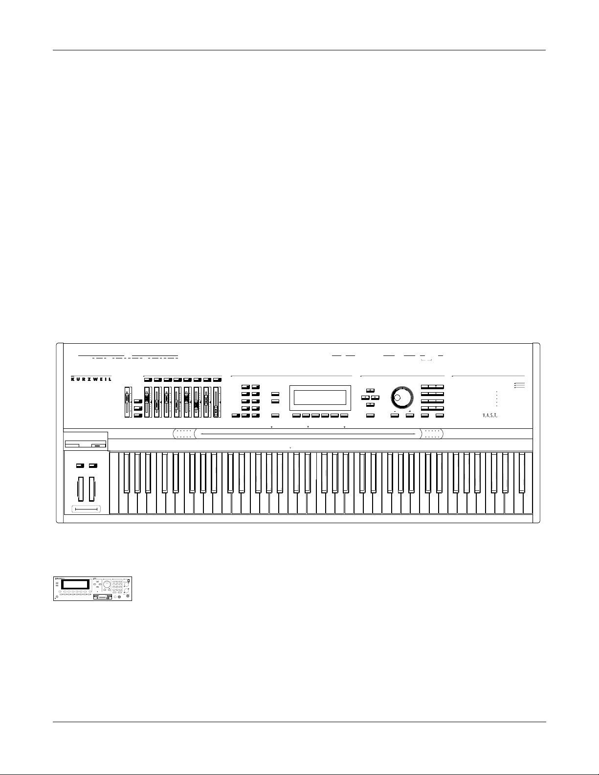
Congratulations, and thanks for purchasing a Kurzweil/Young Chang K2500 Series
instrument. Whether you’ve just gotten a K2500 (illustrated below), the 88-note K2500X, or the
rack-mountable K2500R, you’ve got your hands on an extremely capable musical instrument.
The K2500 Series instruments are packed with great acoustic, electric, and synth sounds—
combined with some of the most advanced synthesis features available, which you can use to
create almost any sound imaginable. If you liked the award-winning K2000, you’ll love the
K2500!
This manual and the accompanying Reference Guide , as well as the video tutorial, will get you
started with your new instrument. You’ll definitely want to keep the manuals handy as you
become an advanced user, too.
H
eadphones
SW1 SW2
ix
M
R
O
B
C
LDRL
R
aster Volume
M
olo
S
ixdown
M
Faders
MIDI
RL
ontrollers
ssignable
AC
132
A
A
LRL
D
igital OutOptical Out
4756 8
CB D
EF
O
ptical In
D
igital In
G
H
L
oZ Right In
L
oZ Left In
iZ In
H
rogram
P MIDI
Previous PgMute 1
Zoom -
Gain -
S
aster
M
etup
Mute 2
Mark
Zoom +
Gain +
C
Q
Mute 3
Samp/Sec
E
FX Bypass
lay/Pause
R
ecord
P
han/Bank
ong
S
Access
Jump
Link
Layer/Zone
ffects
isk
D
Compare
S
top
E
dit
4
C
MIDI
Select
MIDI
OutOut Thru
SCSI
InOut/Thru
SCSI
D
E
ata
ntry
S
witch Pedals
4
Thru
xit
E
Pedals / Breath
CC
213
or
1 32
ABC
4
JKL
7
STU
+/-
UPPER/lower
ancel
C
2Breath
DEF
MNO
8
VWX YZ
0
0 - 9
KDS
Output
1
GHI
695
PQR
C
lear
Space
E
nter
P
ower
K
2500
F
orty-Eight Voices
D
igital Multi Effects
ulti-Track Sequencer
M
xpandable to 28MB of Sound ROM
E
E
xpandable to 128MB of Sample RAM
ynthesisrchitectureariable
echnology
TSAV
A
udio
uts
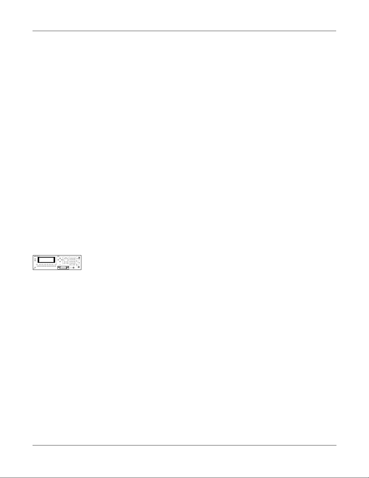
For K2500R Owners
echnology
TSAV
2500RS
K
Sampler
C
han/Bank
Layer/Zone
dit
E
P
rogram
ffects
Access
etup
QS E MIDI
Mute 1
FX Bypass
Mute 2
Mute 3
Zoom -
Zoom +
Samp/Sec
P
ower
ynthesisrchitectureariable
E
xit
MIDI
aster
M
ong
S
isk
D
Mark
Compare
Previous Pg
Jump
Gain +
Gain -
Link
Throughout the Performance Guide and Reference Guide we’ve simplified things by saying just
ptical In
O
3
1
2
oZ
L
ABC
DEF
GHI
5
6
4
JKL
MNO
PQR
Left
7
8
9
"K2500" any time we’re referring to features that are common to all instruments in the K2500
STU
VWX
YZ
+
/
0
CLR
UPPER/lower
0-9
Space
ancel
C
nter
E
Right
iZ
H
Tip=Left
Series. Obviously, though, there are some differences between the rack and keyboard models;
olume
V
eadphone
H
Ring=Right
we’ll point them out where they occur and mark them with a handy K2500R margin symbol
such as the one to the left of this paragraph.
1-1
Page 12

Introduction
Overview of the K2500
Overview of the K2500
The K2500 has been designed to be a versatile instrument both for performance, and for multitimbral sequencing and recording. Its Variable Architecture Synthesis Technology lets you
build sounds from realistic instrumental samples and sampled synth waveforms—then modify
the nature of those sounds through a dazzling array of digital signal processing (DSP)
functions. The K2500 also generates its own synth waveforms, which can be combined with the
samples or used on their own. The K2500 packs 8 Megabytes of on-board sound ROM, and you
can load samples from disk into optional sample RAM.
Before we get into explaining Variable Architecture Synthesis, here are a few of the features that
by themselves make the K2500 an impressive stage and studio machine. It’s fully multitimbral—different programs can be played on each MIDI channel. It’s 48-note polyphonic, for a
full sound no matter how many chords you play. There’s an on-board digital effects processor,
providing up to four simultaneous effects, including realtime effects control, internally or via
MIDI.
In addition to the standard stereo audio output pair, there are eight separate outputs that can be
configured as stereo pairs, or as individual mono outputs. You can also use the separate outputs
as insert points for outboard gear.
The K2500 offers eight SIMM sockets (single, in-line memory modules) so you can add optional
sample RAM, where you can store samples that you’ve loaded from disk. You can add up to
128 megabytes of sample RAM! (Sample RAM is not battery-backed, so RAM samples are
erased from memory when you power down.)
For offline storage, there’s also a floppy drive and two SCSI ports, so you can store files on
floppies or on an external hard disk or load them from a CD-ROM drive. The two SCSI ports
make it easy to chain multiple SCSI devices together. There’s also provision for an internal SCSI
hard disk. You’ll find all this storage potential extremely useful for saving and loading samples,
which can be transferred to and from the K2500 using the standard MIDI sample transfer
format, or the new, faster, parallel SMDI sample transfer format (SCSI Musical Data
Interchange). See the Reference Guide for information about MIDI and SMDI sample transfers.
The K2500’s battery-backed RAM will store about 400 of your own programs, or 30,000 notes
recorded in the sequencer. This sequencer (Song mode) lets you play back MIDI type 0
sequences, record and play back your own songs, and record multi-timbral sequences received
via MIDI. For more onboard storage you can add the P/RAM option, which will increase your
battery-backed RAM to about 1250K, enough to store hundreds of additional programs, setups,
songs, and other objects .
The Local Keyboard Channel feature enables you to use the K2500’s tri-zone setups even if
your MIDI controller can transmit on only one channel. The K2500 will also rechannelize
incoming MIDI information and send it to its MIDI Out port, enabling you to control additional
synths on three different channels.
An optional sampling feature is available, allowing you to make your own mono or stereo
samples using analog or digital inputs.
1-2
And, of course, there’s the incomparable Kurzweil sound. The K2500 comes to you with 200
preset factory programs (called patches, presets, voices, etc. on other synths), as well as 100
multi-zone performance setups. Play them straight from the box, tweak them in any number of
ways, or develop your own programs from scratch—which brings us back to the powerful
programming capabilities of the K2500.
Page 13

What is VAST?
Variable Architecture Synthesis gives the K2500 its unprecedented flexibility. While many other
synthesizers offer a fixed set of DSP tools (typically filtering, pitch, and amplitude modulation)
the K2500’s Variable Architecture lets you arrange a combination of any five DSP functions
from a long list of choices. The functions you choose define the type of synthesis you use.
Each layer of every program has its own DSP architecture, what we call an algorithm . Within
each algorithm, you can select from a variety of DSP functions. Each function can be
independently controlled by a variety of sources including LFOs, ASRs, envelopes, a set of
unique programmable functions (FUNs), as well as any MIDI control message. The many
different DSP functions and the wealth of independent control sources give you an extremely
flexible, truly vast collection of tools for sound creation and modification.
Introduction
What is VAST?
Variable Architecture Synthesis Technology
How the K2500 Works
The K2500 integrates two MIDI-driven components: a sound engine, and a global effects
processor. The sound engine responds to the MIDI events generated by your MIDI controller
and turns them into sounds that are processed within the variable architecture of the
algorithms. The resulting sound can then be routed through the effects processor and to the
MIX or separate audio outputs.
1-3
Page 14

Introduction
How to use this manual
How to use this manual
This manual includes the following:
•
how to connect and power up your K2500, getting around the front panel, and a brief
description of the operating modes.
•
basic editing, including the normal operations of each operating mode.
•
the advanced programming features that make the K2500 so powerful—a number of
familiar synthesis tools and quite a few new ones.
Even if you’re a complete techie, you should read Chapter 3, User Interface Basics. Here you’ll
get a tour of the K2500’s front panel and learn how to navigate through the major functions.
Chapter 4 describes the concept and operation of the K2500’s eight operating modes, with a
brief description of each. Chapters 6 through 13 describe each mode in detail, including the
editors contained within them. Chapters 14 through 17 discuss the advanced editing features.
Chapter 18 shows you how to use the multiple audio outputs to suit your needs. Chapter 19 is
a programming tutorial, giving you specific examples of many of the K2500’s programming
functions. Some are basic, some are advanced. By working through the tutorials, you’ll become
familiar with many synthesis techniques, and you’ll get a first-hand look at how to unleash the
power of the K2500.
When manual text appears in boldface italic ( like this ), you’ll find it described in the Glossary
in the Reference Guide . Only the first one or two occurrences of these words are highlighted.
The best way to read this manual is with your K2500 in front of you. By trying the examples we
give to illustrate various functions, you can get a quick understanding of the basics, then move
on to the more advanced features.
If you like to figure out your equipment for yourself, and normally use manuals only as
reference sources, you’ll probably get the most use out of the Reference Guide that accompanies
this manual, which contains brief descriptions of the K2500’s major operating features, and all
sorts of useful lists— programs , keymaps , algorithms , effects, control sources , and more. A
glossary and complete specifications for the K2500 are also included in the Reference Guide.
1-4
Page 15
Startup
Basic Startup Checklist:
Chapter 2
Startup
If hooking up new gear is familiar to you, and you just want to get going, here’s a quick
description of all the basic things you need to cover to get started with your K2500. The
procedure is pretty much the same whether you have a rack or a keyboard model. If you need
more information, thorough descriptions of each step follow. In either case, check out “Playing
the Presets,” later in this chapter.
Basic Startup Checklist:
•
Install the supplied batteries (if they are packaged separately). See "Battery Installation"
on page 2-2.
•
Mount your K2500R securely in a standard 19-inch MIDI rack, or set it on a hard flat
surface. Keyboard models should either be placed on a sturdy keyboard stand or table. In
either case, make sure to leave plenty of room for ventilation.
•
Connect the power cable.
•
Make sure your sound system is at a safe volume level.
•
Plug in a pair of stereo headphones or run standard (1/4-inch) audio cables from your
amplifier or mixer to the MIX audio outputs on the K2500 (Use the MIX L out for mono).
It’s good practice to make the cable connection to the K2500 (or any instrument) last, since
this will reduce the chance of creating static electricity that can cause an audible "pop"
(and, in extreme cases, cause equipment damage).
K2500R Only
•
echnology
TSAV
2500RS
K
Sampler
C
han/Bank
Layer/Zone
dit
E
P
rogram
ffects
Access
etup
QS E MIDI
Mute 1
FX Bypass
Mute 2
Mute 3
Zoom -
Zoom +
Samp/Sec
P
ower
ynthesisrchitectureariable
ptical In
O
3
1
2
oZ
L
ABC
DEF
GHI
5
6
4
JKL
MNO
PQR
Left
7
8
9
STU
VWX
YZ
+
/
0
E
xit
aster
M
ong
S
isk
D
Mark
Compare
Previous Pg
Jump
Gain +
Gain -
Link
CLR
MIDI
UPPER/lower
0-9
Space
ancel
C
nter
E
Right
iZ
H
Tip=Left
olume
V
eadphone
H
Ring=Right
IMPORTANT: If you will be transporting the rack containing the K2500R, you must
support the back of the unit. It’s fairly heavy, and you don’t want your K2500R to get
damaged when you move the rack around.
•
Most likely, you will connect a MIDI controller to your K2500R. Connect a MIDI cable
from the MIDI Out port of your MIDI controller to the MIDI In port of the K2500R.
•
If your MIDI controller can transmit on more than one MIDI channel, check out Setup
mode by pressing the Setup mode button. Then use the Alpha Wheel to select tri-zone
setups with independent programs, MIDI channels and controller assignments in each
zone.
Start Jamming!
•
Power up your K2500 and begin making some music.
•
If you hear distortion, reduce the gain on your mixing board, or use the pad if it has one.
•
Scroll through the Program list with the Alpha Wheel (the large knob to the right of the
display).
•
Press the Quick Access mode button and use the numeric keys to select from
programmable banks of ten programs or setups.
•
If you don’t hear anything, review these steps, or check the Troubleshooting section in the
Reference Guide .
2-1
Page 16
Startup
Startup—the Details
Startup—the Details
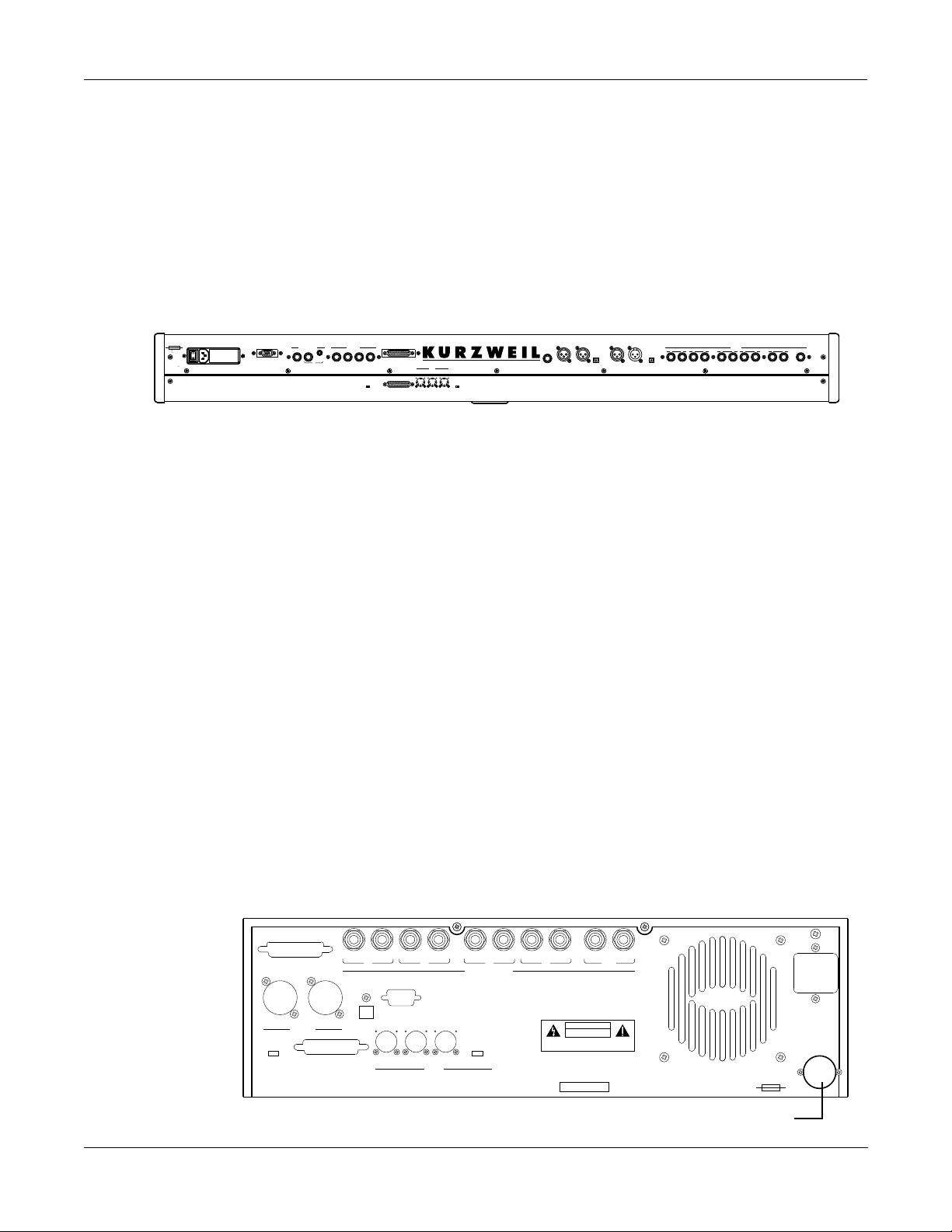
This section will walk you through the hookup of your K2500. We’ll take a look at the rear
panel, then describe the power, audio, and other cable connections.
Before Y ou Start...
Don’t connect anything until you make sure your K2500 is properly and safely situated. Also, if
your K2500 has been out in the cold, give the unit a little time to warm up to room temperature
before starting it, since condensation may have formed inside the K2500.
You’ll probably be mounting a K2500R in a standard 19-inch MIDI rack (it takes up three rack
echnology
TSAV
2500RS
K
Sampler
C
han/Bank
Layer/Zone
dit
E
P
rogram
ffects
Access
etup
QS E MIDI
Mute 1
FX Bypass
Mute 2
Mute 3
Zoom -
Zoom +
Samp/Sec
P
ower
ynthesisrchitectureariable
ptical In
O
3
1
2
oZ
L
ABC
DEF
GHI
5
4
6
JKL
MNO
PQR
Left
7
8
9
spaces). If you will be transporting the rack containing the K2500R, be sure to support the back
STU
VWX
YZ
+
/
0
E
aster
M
ong
S
isk
D
Mark
Compare
Previous Pg
Jump
Gain +
Gain -
Link
CLR
xit
MIDI
UPPER/lower
0-9
Space
ancel
C
nter
E
Right
iZ
H
Tip=Left
olume
V
eadphone
H
Ring=Right
of the K2500R within the rack. If you’re not installing the K2500R in a rack, it should rest on a
hard flat surface. In this case, it must rest on its rubber feet (supplied in the packing carton), and
NOT on the bottom panel.
NEVER block the ventilation openings on the bottom or rear panels; doing so can cause
overheating and serious damage. To provide adequate ventilation, the rear panel should be at
least four inches from any vertical surface. There are no user-serviceable parts in the K2500 .
Under no circumstances should you attempt to remove any panels (except for battery
installation or replacement). If you attempt to open your K2500, you’ll risk electric shock, and
you’ll void your product warranty.
Battery Installation
We’ve included three AA batteries for your K2500’s battery-backed RAM. Depending on when
your K2500 was shipped, we may not have installed the batteries at the factory because they
would drain during shipping. If you’ve found three batteries shipped in the box with your unit,
you should install the batteries before you start up your K2500. Otherwise, continue on to the
next section.
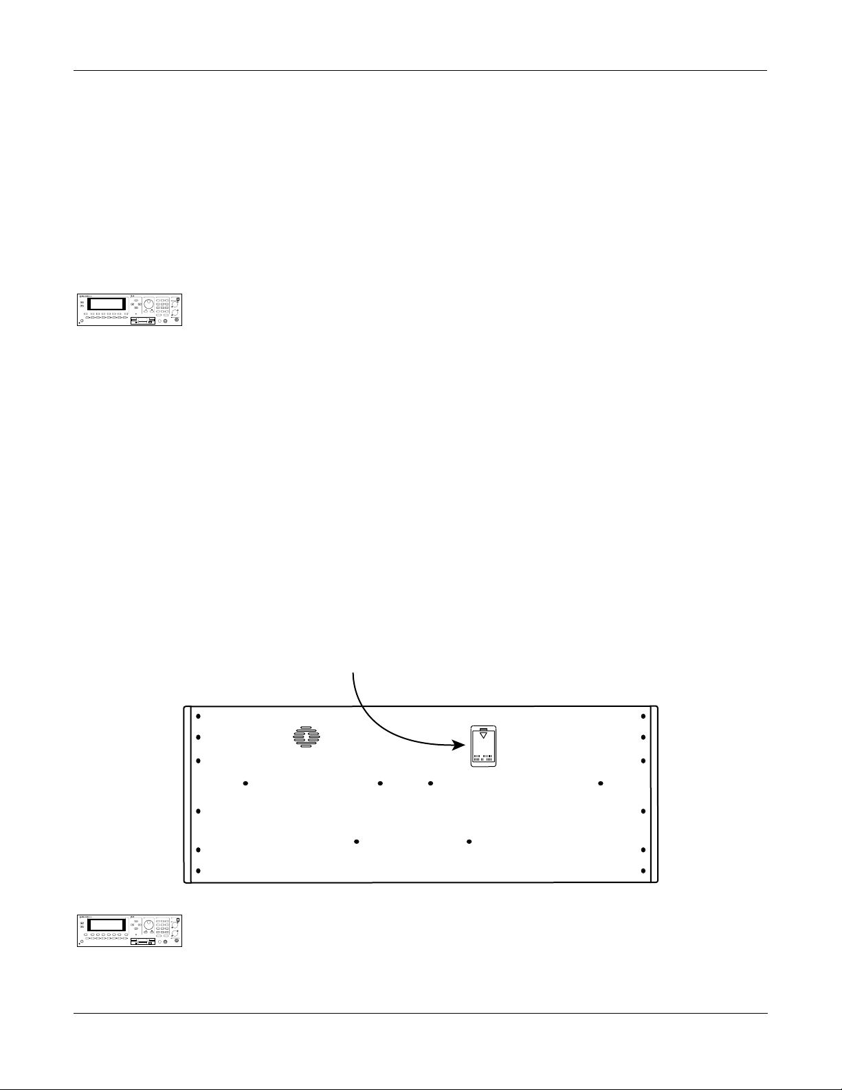
Locate the battery compartment in the lower right-hand corner of the rear panel of the K2500R
(refer the illustration on the following page) or the small door on the bottom of the K2500
keyboard models, as shown below.
Battery Compartment
K
C
han/Bank
Layer/Zone
dit
E
P
rogram
etup
Mute 2
Mute 1
Zoom +
Zoom -
P
ower
2-2
2500RS
QS E MIDI
Mute 3
Samp/Sec
Sampler
ffects
Access
FX Bypass
ynthesisrchitectureariable
ptical In
O
3
1
2
oZ
L
ABC
DEF
GHI
5
4
6
JKL
MNO
PQR
Left
7
8
9
then turning it counterclockwise until it pops out. Slide the three batteries, all positive side out,
STU
VWX
YZ
+
/
0
E
aster
M
ong
S
isk
D
Previous Pg
Jump
Mark
Compare
Gain -
Link
Gain +
CLR
xit
MIDI
UPPER/lower
0-9
Space
ancel
C
nter
E
Right
iZ
H
Tip=Left
olume
V
eadphone
H
Ring=Right
into the compartment. Install the battery compartment cover by lining up the tabs, pushing the
cap inward, then turning it 90
°
.
Remove the battery compartment cover by inserting a flat-head screwdriver or coin into its slot,
echnology
TSAV
When you start up your unit for the first time after installing the batteries, it will take a few
minutes to initialize all of its memory. This will not happen on every power up.
Page 17
Connecting the Power Cable (Line Cord)
The K2500 runs on 100-, 120-, 220-, or 240-Volt AC power at 50—60 Hz. Your dealer will set the
voltage switch to match the voltage in your area. The voltage level is set with a selector on the
rear panel of the keyboard models of the K2500. On the K2500R, however, the voltage setting
can only be changed by an authorized Kurzweil service center.
When you’ve connected the cable at the K2500 end, plug it into a grounded outlet. If your
power source does not have the standard three-hole outlet, you should take the time to install a
proper grounding system. This will assure you of avoiding problems with audio hum, and will
reduce the risk of a shock hazard.
witch Pedals12S
Pedals / Breath
Output
KDS
100/120V F 2.0A 250V slow-blow
230/240V F 1.0A 250V slow-blow
100/120/230/240V AC
1.5/.75 A
50-60 Hz
ATTENTION
WARNING
FOR CONTINUED PROTECTION AGAINST THE RISK OF FIRE,
REPLACE ONLY WITH THE SAME TYPE AND RATING OF FUSE.
UTILISER UN FUSIBLE DE RECHANGE DE MEME TYPE.
CC
21
reath
B
or
3
SCSI
Disable Enable
SCSI
Thru
4
SCSI
MIDI
Select
Termination
MIDI
Thru OutOut
In
Thru/Out
2
K
Connecting the Audio Cables
Did you turn down the level on your PA yet?!
After you’ve turned down the level on your sound system, you can rig the K2500’s audio
connections using a pair of mono audio cables. You’ll find ten 1/4-inch jacks near the top of the
rear panel. For now, connect one end of each audio cable to your mixing board or PA system
inputs, and connect the other end to the jacks marked MIX L and R on the rear panel of the K2500.
If you have only one input available, use the K2500’s MIX L output to get the full signal in mono.
It’s always a good idea to make the cable connection to the K2500 (or any instrument) after
you’ve made your other audio connections, since this will reduce the chance of creating static
electricity that can cause an audible "pop" (and, in extreme cases, cause equipment damage).
Turn to Chapter 18 for more detailed information about the K2500’s audio configuration.
050
H
iZ In oZ Right In
Ring=Right
Tip=Left
oZ Left In
LL
ptical InOigital InDigital OutDptical Out
Startup—the Details
A
uts
O
udio
C
D
LARLRBL
O
R
L
R RL
(mono)
ixMeadphones
H
Startup
Connecting MIDI
The simplest MIDI configuration uses a single MIDI cable, from the MIDI Out port of your
MIDI controller to the MIDI In port of the K2500. There are all sorts of possible configurations,
including additional synths, personal computers, MIDI effects processors, and MIDI patch
bays. Depending on your system, you may want to use the K2500’s MIDI Thru port to pass
MIDI information from your MIDI controller to the K2500 and on to the next device in your
system. You can also connect MIDI devices to the K2500’s MIDI Out port, which can send
channelized MIDI information from your MIDI controller. See the discussion of the Local
Keyboard Channel parameter in Chapter 10.
NOTE: You can perform a quick check of the K2500R and your audio system without a MIDI
controller connected to the K2500R. Hold down the CANCEL button on the alphanumeric pad
and press any other alphanumeric button, and you should hear notes. See "The Panel Play
Feature" in Chapter 3 for more information about this feature.
SCSI Thru
SCSI Term.
Disable / Enable
THIS DEVICE COMPLIES WITH PART 15 OF THE FCC RULES. OPERATION IS SUBJECT TO THE FOLLOWING
TWO CONDITIONS: (1) THIS DEVICE MAY NOT CAUSE HARMFUL INTERFERENCE, AND (2) THIS DEVICE MUST
ACCEPT ANY INTERFERENCE RECEIVED, INCLUDING INTERFERENCE THAT MAY CAUSE UNDESIRED OPERATION.
Digital
CAUTION
DO NOT OPEN
RLLR
Mix
Made in KoreaYoung Chang Akki, Co., LTD
FOR CONTINUED PROTECTION
WARNING:
AGAINST THE RISK OF FIRE, REPLACE ONLY
WITH SAME TYPE AND RATING OF FUSE.
ATTENTION:
UTILISER UN FUSIBLE DE
RECHANGE DE MEME TYPE.
100/120V ~ T 2.00A 250V SLOW-BLOW
220/240V ~ T 1.00A 250V SLOW-BLOW
100/120/220/240V ~ AC
1.5/0.75A
48-65HZ
RL
BA
KDS Output
Optical Out
OutIn
MIDI
RLLR
Audio Outs
MIDI Select
Thru / OutOutThru / OutInSCSI
Mfr: Serial No.
DC
ATTENTION:
WARNING:
SHOCK, DO NOT EXPOSE THIS PRODUCT TO RAIN OR
MOISTURE.
RISK OF ELECTRIC SHOCK
RISQUE DE CHOC ELECTRIQUE
NE PAS OUVRIR
TO REDUCE RISK OF FIRE OF ELECTRIC
Battery Compartment
2-3
Page 18

Startup
Playing the Presets
Connecting SCSI
Switching On the Power
You may not have a hard disk or other SCSI device to connect to your K2500 right away, but if
you do, you can connect it to either of the SCSI ports. Please read the following information
carefully; it’s very important. Also, there’s a collection of SCSI tips in Chapter 10 of the Reference
Guide.
CAUTION: If you plan to connect more than one SCSI device to the K2500 (including an Apple
Macintosh®), you must terminate your SCSI chain properly. Turn to Chapter 13 and read the section
called “SCSI Termination.” You can lose data, and possibly damage your K2500 and SCSI devices if
they’re not terminated properly.
The power switch is located at the lower left of the front panel. When you power up, the
display will briefly say “Welcome to the K2500!” The Program Mode display will then appear.
It looks like the diagram below (the programs shown in the diagram don’t necessarily exist):
ProgramMode||||Xpose:0ST|||<>Channel:1||
!!!!!!!!!!!!!!!!!!@|198|James|Jams||||||
KeyMap|Info|||||||#|199|Default|Program|
|Grand|Piano||||||#| ||1|Righteous|Piano|
||||||||||||||||||#|||2|Mondo|Bass||||||
||||||||||||||||||#|||3|Killer|Drums||||
%%%%%%^%%%%%%^%%%%$|||4|Weeping|Guitar||
Octav-| Octav+| Panic|| Sample| Chan-|| Chan+
Set the volume at a comfortable level. You’ll get the best signal-to-noise ratio if you keep the
K2500 at full volume (turn the volume knob fully clockwise), and adjust the level from your
mixing board. You may also want to adjust the display contrast. This is done with the Contrast
parameter in Master mode. See Chapter 11. As you trigger notes from your MIDI controller,
you’ll see the MIDI LED flash. If it doesn’t flash, check your MIDI cables and connections.
Playing the Presets
There are three things you’ll want to check out right away: programs, setups and Quick Access
banks. In performance situations, you’ll be selecting your sounds using one of these three
methods.
Programs
The K2500 powers up in Program mode, where you can select and play programs stored in
ROM or RAM . Programs are preset sounds composed of one to three layers of samples or
waveforms—they’re called patches, voices, and presets on other instruments. If you’ve left
Program mode, just press the Program mode button to return.
2-4
Take a minute to familiarize yourself with the Program mode display. It gives you some helpful
basic information, like the MIDI transposition, what MIDI channel you’re on, and which
program is currently selected. The box at the left of the display tells you which keymap is used
by each layer of the current program (a keymap is a collection of samples). The line under each
keymap name gives a rough indication of the keyboard range of the layer. In the figure below,
the Grand Piano keymap covers the full range from C 0 to C 8. You can change MIDI channels
with the Chan- and Chan+ buttons under the display. You can transpose by octaves by
pressing the Octav buttons under the display (if the LocalKbdCh parameter on the RECV page
in MIDI mode matches the transmitting channel of your MIDI controller—see Chapter 10). The
bottom line of the display identifies the function of each of the buttons beneath the display.
Page 19

Startup
Playing the Presets
ProgramMode||||Xpose:0ST|||<>Channel:1||
!!!!!!!!!!!!!!!!!!@|199|Default|Program|
KeyMap|Info|||||||#|200*Crystal|Horn||||
|Grand|Piano||||||#|||1|Righteous|Piano|
||||||||||||||||||#|||2|Mondo|Bass||||||
||||||||||||||||||#|||3|Killer|Drums||||
%%%%%%^%%%%%%^%%%%$|||4|Weeping|Guitar||
Octav-|Octav+|Panic||Sample|Chan-||Chan+
When you want to change programs, you have several options. The K2500 has six different
settings for responding to MIDI program change commands. These are explained in Chapter
10, so we won’t go into them here. You should be able to change programs by sending program
change commands from your MIDI controller. Of course, you can always change programs
from the K2500’s front panel using the Alpha Wheel. Turning it left or right will scroll through
the program list. You can also change programs using the cursor buttons, or the Plus/Minus
buttons under the Alpha Wheel. You can also use the CHAN/BANK buttons or the cursor
buttons while in Program mode.
Setups
Be sure to try whatever performance controls your MIDI controller has: the Pitch Wheel, Mod
Wheel, and switch or control pedals—different programs respond to them in different ways.
Attack velocity and aftertouch also have varying effects. Check the tear-out sheets at the back
of this manual for lists of factory programs and setups. There’s also a list of programs in the
Reference Guide, describing how each program responds to specific MIDI control messages.
If you don’t hear anything, see the troubleshooting section in the Reference Guide.
Setups are preset combinations of programs. Starting with V2 software, setups can have up to
eight zones, each of which can be assigned to any range of the keyboard (overlapping or split).
Each zone can have its own program, MIDI channel, and MIDI control assignments. You can
make use of setups even if your MIDI controller can transmit on only one MIDI channel at a
time. See the parameter called Local Keyboard Channel in Chapter 10.
Press the Setup mode button to the left of the display. Its LED will light, telling you that you’re
in Setup mode. Notice that the Setup mode display is similar to the Program mode display. If
the setup has three or fewer zones, the box at the left shows you the programs assigned to each
of the setup’s three zones, and which MIDI channel is used for each program. If the setup is
composed of more than three zones, then the box displays a series of horizontal lines
illustrating the approximate key ranges of the zones.
SetupMode||||||Xpose:0ST||||||||||||||||
!!!!!!!!!!!!!!!!!!@|201*Friday|Gig||||||
Chan/Program|Info|#|202*Bop|Rock|Reggae|
1||||9|Cool|Traps|#|||1|Jazz|Trio|||||||
2|||18|Sly|Acoust|#|||2|All|Percussion||
3|||22*Izit|Jimmy|#|||3|Heavy|Metal|||||
%%%%%%^%%%%%%^%%%%$|||4|To|Sequencer||||
Octav-|Octav+|Panic||Sample|||||||||||||
2-5
Page 20

Startup
Playing the Presets
Quick Access
A really convenient way to select programs and setups is to use Quick Access mode, where you
select a Quick Access bank from a list of factory preset or user-programmed banks. Each bank
contains ten memory slots, or entries, where you can store any combination of programs or
setups. While you’re in Quick Access mode, any program or setup can be selected with the
numeric buttons 0 through 9.
The K2500 comes with a few Quick Access banks already programmed so you can get an idea
of how they work. You’ll probably create your own Quick Access banks to help you select
programs and setups with a minimum of searching. Press the Quick Access mode button to the
left of the display. Its LED lights, to tell you you’re in Quick Access mode. You’ll see a display
that looks like this:
QuickAccessMode|||<>Bank:1|For|Show|1|||
Silk|Rhodes|||POLY|TOUCH||||Voice+String
NastyTrombone|SINK|MONSTA|||Waterflute||
Soon||||||||||Jazz|Trio|2|||Fretless|Bas
||||||||||||||VELVETEEN|||||||||||||||||
||||||||||||||||||||||||||||||||||||||||
|Xpose:0ST|||SINK|MONSTA||||||||Chan:1||
Octav-|Octav+|Panic||Sample|Chan-||Chan+
The top line of the display tells you which Quick Access bank is selected. Use the CHAN/
BANK buttons (to the left of the display) to scroll through the banks. The names of each of the
ten entries in the bank are listed in the center of the display. Many of their names will be
abbreviated. The currently selected entry’s full name is shown near the bottom of the display.
The amount of transposition is displayed to the left of the entry name. If the current entry is a
program, you’ll see the current keyboard (MIDI) channel displayed to the right of the entry’s
name. If it’s a setup, you’ll see the word “Setup.”
The entries on the Quick Access page are arranged to correspond to the layout of the numeric
buttons on the alphanumeric pad. On the page above, for example, the program “SINK
MONSTA” is entry 5, and can be selected by pressing 5 on the alphanumeric pad.
The Panic button (the button below the word “Panic” in the bottom line of the display) will
send an All Notes Off and an All Controllers Off message to the K2500, and over all 16 MIDI
channels. Press the View button to show the currently selected bank entry in large type. Press it
again to return to the normal view.
When you’re ready to create your own Quick Access banks, turn to Chapter 8 to learn about the
Quick Access Editor.
2-6
Page 21

Performance Controls
From your MIDI controller
The K2500 responds to attack velocity and release velocity, as well as mono and poly pressure
(aftertouch) messages. It will also respond to most standard MIDI control parameters; see
“MIDI and Setup Control Parameters" below.
Volume knob
The Volume knob controls the volume at the MIX (stereo) audio outputs and at the headphone
jack. The individual outputs and MIDI volume are not affected by this knob.
MIDI and Setup Control Parameters
The K2500 responds to most standard MIDI control messages, including Pitch Wheel, Mod
Wheel, switch pedals, control pedals, and control sliders. The K2500’s response to these
controls is set on the XMIT (Transmit) page in MIDI mode, and works in conjunction with the
Local Keyboard Channel parameter on the RECV (Receive) page in MIDI mode. This is
described fully in Chapter 10. For now, you’ll probably find that the K2500 responds
predictably to most of these controls. If you want to change its response, turn to Chapter 10 and
read the section covering the Local Keyboard Channel parameter.
Startup
Performance Controls
You can also use the K2500 to relay control messages from your MIDI controller to other MIDI
devices connected to the K2500’s MIDI Out port. This is also controlled by the Local Keyboard
Channel parameter (MIDI RECV page) in combination with the settings for the control
parameters on the MIDI XMIT (transmit) page or the Setup mode page.
2-7
Page 22

Startup
K2500 Boot Loader
K2500 Boot Loader
The Boot Loader lets you install a new K2500 operating system and/or new K2500 ROM
objects, from a SCSI device or the floppy drive into flash ROM. The Boot Loader also provides
hard reset and diagnostics options.
Note: Your K2500 comes from the factory with the operating system and ROM objects already installed.
You do not need to run the K2500 Boot Loader to start up a new K2500.
Starting the Boot Loader
When you start the K2500, it displays a "Please wait..." message and waits for approximately 2
seconds. Press and release the Exit key while the "Please wait..." message is displayed to start
the boot loader. Otherwise, the K2500 will start up normally.
The Boot Loader’s Menus resemble K2500 dialog boxes. That is, they consist of a series of
labels and a highlight bar that is used to select one of the labels. You can use the arrow keys to
move the highlight bar up, down, right, and left. Press the OK soft button to invoke the
highlighted menu option. Additionally, the data wheel and Enter key may be used to move the
highlight bar and invoke the selected action.
Boot-loader Main Menu
When the boot loader is first invoked, its main menu is displayed, as shown below.
-------|K2500|Boot|Loader|v1.01|------|||||||||||||||||||||||||||||||||||||||
|||Install|System|||||Hard|Reset|||||||
|||Install|Objects||||Run|Diags||||||||
|||Run|System|||||||||Fixed|Diags||||||
|||||||||||||||||||||||||||||||||||||||
||||||||||||||||||||||||||||||||||OK|||
Initially, the "Install System" option is highlighted. After invoking various actions, however,
other options may be selected by default, as the context suggests, upon returning to this menu.
Install System / Install Objects
Use "Install System" to install the K2500 operating system and diagnostics by loading them
from a floppy or from a SCSI device and programming them into Flash ROM. Use "Install
Objects" to install ROM objects into Flash ROM. After either option is invoked, a dialog box
such as the following will be displayed.
|||||||||||||||||||||||||||||||||||||||
|||||||||||||||||||||||||||||||||||||||
||Device|to|install|from:||floppy||||||
|||||||||||||||||||||||||||||||||||||||
||||SCSI|ID|of|this|unit:||N/A|||||||||
|||||||||||||||||||||||||||||||||||||||
|||||||||||||||||||||||||||Cancel|||OK|
2-8
From this dialog box, you can select which device contains the system or ROM-objects file. This
is done using the alpha wheel, the + and - keys, and the cursor control keys in the same way
that the K2500 engine software does. If you choose to install from a SCSI device, the SCSI ID of
this unit will change from "N/A" to "SCSI 6." If there is another device on your SCSI bus with
Page 23

Startup
K2500 Boot Loader
an ID of 6, you will need to change the SCSI ID of this unit to a free SCSI ID. At this point you
can continue by hitting the OK soft-button or abort the operation by pressing the one labeled
Cancel. Canceling the operation will return you to the Boot Loader menu, and the "Run
System" option will be highlighted.
When you press OK, the K2500 will try to access the drive in question and scan it for files. If it
is successful, a screen such as the following will then appear:
|||||||||||||||||||||||FILE1.KOS|||||||
|||||||||||||||||||||||DIR1||||<DIR>|||
|||||||||||||||||||||||FILE1.K25|||||||
|||||File|to|Install:||FILE1.KRZ|||||||
|||||||||||||||||||||||VLABEL|||<VOL>||
|||||||||||||||||||||||||||||||||||||||
|||||||NewDrv|Root|Parent||Cancel|||OK|
While this screen is displayed, you can use the up and down cursor keys, the alpha wheel, or
the + and - keys to highlight different items in the file list. Names that have "<DIR>" displayed
to their right are sub-directories. If the disk has a volume label, it will be displayed in the list,
marked with "<VOL>." Operating system files typically have a ".KOS" extension, while ROM
object files have a ".KRZ" extension. The OK soft-button selects the highlighted file for loading,
or changes to the highlighted directory. The Cancel button aborts the installation and returns
to the menu. Parent changes to the current directory's parent directory, while Root changes to
the disk's root directory. The NewDrv button returns to the previous screen, allowing you to
choose a different drive from which to install.
After you select a file by pressing the OK button, you will be asked to confirm the installation.
The K2500 will display a message of the form "Ready to install operating system from filename
on device" or "Ready to install ROM objects from filename on device." When it displays this
message, it will fill in filename and device with the name of the file and device you have selected.
To confirm that you want to proceed, press the OK soft-button. If you do so, you will not be
able to interrupt the installation. Alternatively, the Cancel button will return you to the menu,
or the Choose button will allow you to select a different device or file from which to install.
While the K2500 is installing the file into Flash ROM, the top line of the display will gradually
fill to indicate the progress of the operation. Note that operating system files and ROM object
files are of different formats. If you try to install a file using the incorrect menu option, the
K2500 will think the file is corrupt and will refuse to install it into Flash ROM. If this happens,
simply choose the correct menu option from the Boot Loader's main menu, and repeat the
installation.
If there is a problem accessing the drive or installing the file, an error message will be
displayed. At this point, you can (1) abort the operation with the Abort soft button and return
to the menu, (2) press the Retry button to try the operation again, or (3) choose another device
or file by pressing the Choose button.
Run System
The "Run System" option executes the engine software. When this option is invoked, the
operating system and ROM setups are checked for integrity. If either does not appear to be
installed, a message will be displayed explaining this. If this happens, you can (1) double press
the Run Anyhow soft buttons and be given a chance to try to run the system anyhow, knowing
that the machine might crash, (2) install the uninstalled portion with the Instal button, or (3)
return to the menu by using the Menu button. If you do the latter, the menu will be displayed
with the "Load System" or "Load Setups" option highlighted as appropriate.
2-9
Page 24

Startup
Software Upgrades
Hard Reset
Run Diags
The "Hard Reset" option causes all user RAM to be erased. When you select this option, a strict
warning message is displayed. You must press the up and down cursor keys simultaneously to
actually erase the RAM. If you push any other button or turn the data wheel, the operation is
aborted, and the menu is displayed with the "Run System" option highlighted. Otherwise, the
RAM will be marked for re-initialization, and a message declaring this fact will appear prior to
return to the menu. When the menu reappears, it will have the "Run System" option
highlighted.
The "Run Diags" option executes the diagnostics that are loaded with the system. When you
choose "Run Diags", the K2500 checks its operating system for integrity. If it does not appear to
be installed, a message will be displayed explaining this. If this happens, you can (1) double
press the Run Anyhow soft buttons and be given a chance to try to run the diagnostics anyhow,
knowing that the machine might crash, (2) install the operating system with the Instal button,
or (3) return to the menu by using the Menu button. If you do the latter, the menu will be
displayed with the "Load System" or "Load Setups" option highlighted as appropriate. Some
diagnostic tests erase the non-volatile user RAM, and you will be warned of this fact before
continuing.
Restart your K2500 to leave the diagnostics and return to regular operation.
Fixed Diags
The "Fixed Diags" option executes the diagnostics that are contained in the boot block. Some
diagnostic tests erase the non-volatile user RAM, and you will be warned of this fact before
continuing.
Restart your K2500 to leave the diagnostics and return to regular operation.
Software Upgrades
Part of the beauty of the K2500 is the ease with which you can upgrade its operating system
and objects (programs, setup, etc.) using the boot loader. Kurzweil and Young Chang have a
long history of support for our instruments; the K250, K1000, and K2000 were continuously
being improved, and these improvements were always made available to instrument owners in
the form of software upgrades. Upgrades to these instruments, however, usually required
replacing ROM chips, which had to be done at a service center. Even though this was usually
inexpensive, it did involve some costs.
Upgrading your K2500’s software is simple, painless, and – generally – free! As upgraded
software becomes available, you can either get new disks from your Young Chang dealer or
download the new stuff from a network bulletin board. For example, V2 software, released
concurrently with the K2500 keyboards, offers a greatly enhanced Setup mode – valuable for
racks as well as keyboards.
To stay in touch, check out our World Wide Web site:
2-10
http://www.youngchang.com/kurzweil/
Page 25

User Interface Basics
Mode Selection
Chapter 3
User Interface Basics
Chapter 3 will show you how to get around the front panel of your K2500. Your interactions can
be divided into three primary operations: mode selection, navigation, and data entry.
Mode Selection
The K2500 is always in one of eight operating modes. The modes are selected by pressing one
of the eight buttons beneath the display—the ones with LEDs to their right. Selecting a mode
gives you access to a large set of related parameters. Only one mode can be selected at a time.
The modes are:
•
PROGRAM MODE: Select and play programs, and modify them with the Program
Editor . Rearrange and modify samples in the Keymap and Sample Editors.
•
SETUP MODE: Select and play setups (eight keyboard zones with independent MIDI
channel, program and control assignments), and modify them with the Setup Editor.
•
QUICK ACCESS MODE: Select from a list of preset banks, each containing a list of ten
programs and/or setups that can be viewed in the display for easy selection. Modify the
preset banks and create your own with the Quick Access Editor.
•
EFFECTS MODE: Define the behavior of the on-board global effects processor. Modify
the preset effects and create your own with the Effects Editor.
•
MIDI MODE: Define how your K2500 sends and receives MIDI information, and
configure each channel to receive independent program, volume, and pan messages that
override the normal Program mode settings.
•
MASTER MODE: Define performance and control characteristics for the entire K2500.
•
SONG MODE: Use the K2500’s sequencer to record and play back your keyboard
performance, play type 0 MIDI sequences, and record multi-timbral sequences received
via MIDI.
•
DISK MODE: Interface with the K2500’s floppy disk drive, an external SCSI device, or an
optional internal SCSI disk to load and save programs, setups, samples, and more.
Mode Buttons
The mode buttons are labeled in white. When you press a mode button, the LED to its right
lights up to indicate that the mode has been selected. If pressing a mode button does not light
its LED, press the EXIT button one or more times, then try again.
The green labeling under each mode button indicates special functions that relate to some of
the K2500’s editors. These functions are described in Chapter 5.
Navigation
The navigation section of the front panel consists of the display and the buttons surrounding it.
These navigation buttons will take you to every one of the K2500’s programming parameters.
The Display
Your primary interface with the K2500 is its backlit graphic display. As you press various
buttons, this fluorescent display reflects the commands you enter and the editing changes you
make. The ample size of the display (240-by-64 pixels ) enables you to view lots of information
at one time.
3-1
Page 26

User Interface Basics
Mode Selection
Pages
ProgramMode||||Xpose:0ST|||<>Channel:1||
!!!!!!!!!!!!!!!!!!@|200*Analog|Jam||||||
KeyMap|Info|||||||#|202*Heart|Strings|||
|Grand|Piano||||||#| ||1|Righteous|Piano|
||||||||||||||||||#|||2|Mondo|Bass||||||
||||||||||||||||||#|||3|Killer|Drums||||
%%%%%%^%%%%%%^%%%%$|||4|Weeping|Guitar||
Octav-| Octav+| Panic|| Sample| Chan-|| Chan+
Within each mode, the functions and parameters are organized into smaller, related groups that
appear together in the display. Each one of these single-screen groups of parameters is called a
page . Each mode has what we call an entry level page; it’s the page that appears when you
select that mode with one of the mode buttons. Within each mode and its editor(s), the various
pages are selected with the navigation buttons. There are many pages, but there are a few
features common to each page. The diagram below shows the entry level page for Program
mode.
The T op Line
On the top line of most pages, there’s a reminder of which mode you’re in and which page
you’re on. Many pages display additional information in the top line, as well. The Program
mode page above, for example, shows you the current amount of MIDI transposition and the
currently selected MIDI channel. The top line is almost always “reversed”—that is, it has a
white background with blue characters.
The Bottom Line
The bottom line is divided into six (sometimes fewer) sets of reversed characters that serve as
labels for the six buttons directly beneath the display. These labels—and the functions of the
buttons—change depending on the currently selected page. Consequently the buttons that
select these functions are called “soft” buttons.
The Soft Buttons
The soft buttons are called “soft” because their functions change depending on the currently
selected mode. Sometimes they perform specific functions, like changing MIDI channels in
Program mode. In the Program Editor, they’re also used to move to different pages of
programming parameters.
The Cursor Buttons
To the right of the display are four buttons arranged in a diamond fashion. These are called the
cursor buttons. They move the cursor around the currently selected page, in the direction
indicated by their labels. The cursor is is a highlighted (reversed) rectangle (sometimes it’s an
underscore). It marks the value of the currently selected parameter.
3-2
Programming the K2500 involves selecting various parameters and changing their values.
Parameters are selected by highlighting their values with the cursor. The highlighted value can
be changed with any of the data entry methods described in the data entry section below.
Page 27
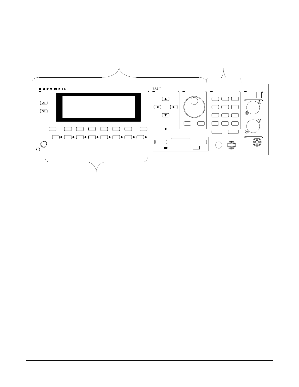
C
han/Bank
Layer/Zone
P
ower
E
dit
P
rogram
Mute 1
Zoom -
2500RS
K
Access
etup
QS E MIDI
Mute 2
Mute 3
Zoom +
Samp/Sec
Sampler
FX Bypass
Navigation Data Entry
echnology
TSAV
ynthesisrchitectureariable
E
ffects
Previous Pg
Gain -
M
Mark
Gain +
aster
S
Jump
Link
xit
ong
isk
D
Compare
MIDI
UPPER/lower
User Interface Basics
Mode Selection
ptical In
O
DEF
MNO
VWX
0-9
2
5
8
0
E
eadphone
H
CLR
Space
nter
PQR
3
oZ
L
GHI
6
9
YZ
iZ
H
1
ABC
4
JKL
7
STU
+
-
/
ancel
C
olume
V
Right
Tip=Left
Ring=Right
Left
Mode Selection
The MIDI LED
Below the cursor buttons is a red LED labeled MIDI. This LED will flash whenever the K2500
receives MIDI information from your MIDI controller.
The CHAN/BANK Buttons
To the left of the display are two buttons labeled “CHAN/BANK.” Their function is related to
the two small arrows— <|> —that appear in the top line of many different pages. When you
see these arrows, you can use the CHAN/BANK buttons to scroll the values of the parameter
that appears to the right of the arrows. The arrows don’t have to appear in the top line,
however, for the CHAN/BANK buttons to have an effect. In Program mode, for example, they
shift through the MIDI channels, showing the program assigned to each channel.
When you’re in the Program editor, the CHAN/BANK buttons let you view each layer in the
program. You can see the corresponding parameters in each layer by scrolling through the
layers with these buttons. In the Setup editor, the CHAN/BANK buttons scroll through the
zones in the current setup. In Quick Access mode, they scroll through the Quick Access banks,
and in Song mode they scroll through record tracks.
We’ll let you know, when applicable, what the CHAN/BANK buttons do.
The EDIT Button
The EDIT button activates each of the K2500’s editors, and acts as a shortcut to many pages
within the Program Editor. Pressing the EDIT button tells the K2500 that you want to change
some aspect of the object marked by the cursor. For example, when a program is selected and
you press EDIT, you enter the Program Editor. If a setup is selected, you enter the Setup Editor.
There are editors accessible from every mode except Disk mode. To enter an editor, choose one
of the modes (mode selection), and press EDIT. An editing page for that mode will appear. You
can then select parameters (navigation) and change their values (data entry). If the value of the
selected parameter has its own editing page, pressing the EDIT button will take you to that
3-3
Page 28

User Interface Basics
Data Entry
Data Entry
page. For example, in the Program Editor, on the PITCH page, you might see LFO1 assigned as
the value for Pitch Control Source 1. If you select this parameter (the cursor will highlight its
value—LFO1 in this case), then press the EDIT button, you’ll jump to the page where you can
edit the parameters of LFO1. Naturally, you can find every page in the current editor by using
the soft buttons, but often it’s easier to use the EDIT button shortcut.
The EXIT Button
Press EXIT to leave the current editor. If you’ve changed the value of any parameter while in
that editor, the K2500 will ask you whether you want to save your changes before you can leave
the editor. See Chapter 5 for information on saving and naming. The EXIT button also takes you
to Program mode if you’re on the entry level page of one of the other modes. If at some point
you can’t seem to get where you want to go, press EXIT one or more times to return to Program
mode, then try again.
The data entry section of the front panel includes the Alpha wheel, the Plus/Minus buttons,
and the 14-button alphanumeric pad.
The Alpha Wheel
The Alpha Wheel is especially useful because it can quickly enter large or small changes in
value. If you turn the Alpha Wheel one click to the right, you’ll increase the value of the
currently selected parameter by one increment. One click to the left decreases the value by one
increment. If you turn it rapidly, you’ll jump by several increments.
The Plus/Minus Buttons
These buttons are located just under the Alpha Wheel. The Plus button increases the value of
the currently selected parameter by one, and the Minus button decreases it by one. These
buttons are most useful when you’re scrolling through a short list of values, or when you want
to be sure you’re changing the value by one increment at a time. One press of the Plus or Minus
button corresponds to one click to the right or left with the Alpha Wheel. These buttons will
repeat if pressed and held.
Pressing the Plus and Minus buttons simultaneously will move you through the current list of
values in large chunks instead of one by one. Often this is in even increments (10, 100, etc.).
Don’t confuse these buttons with the +/- button on the alphanumeric pad. This button is used
primarily for entering negative numeric values and switching from uppercase to lowercase
letters (and vice versa).
The Alphanumeric Pad
As its name implies, this set of 14 buttons lets you enter numeric values, and to enter names one
character at a time. Depending on where you are, the K2500 automatically enters letters or
numerals as appropriate (you don’t have to select between alphabetic or numeric entry).
3-4
When you’re entering numeric values, press the corresponding numeric buttons, ignoring
decimal places if any (to enter 1.16, for example, press 1, 1, 6, ENTER). The display will reflect
your entries, but the value won’t actually change until you press ENTER. Before pressing
ENTER, you can return to the original value by pressing CANCEL. Pressing CLEAR is the same
as pressing 0 without pressing ENTER.
When entering names, you’ll use the left/right cursor buttons or the <<< / >>> soft buttons
to move the cursor to the character you want to change. Use the labels under the alphanumeric
buttons as a guide to character entry. Press the corresponding button one or more times to
insert the desired character above the cursor. The CANCEL button is equivalent to the >>>
soft button, and ENTER is the same as OK. The CLEAR button replaces the currently selected
character with a space. The “+/-” button toggles between uppercase and lowercase letters.
Page 29

User Interface Basics
Data Entry
Double Button Presses
Pressing two or more related buttons simultaneously executes a number of special functions depending on
the currently selected mode. Make sure to press them at exactly the same time.
In This Mode: These Buttons: Will Do This:
(Pressed simultaneously)
PROGRAM MODE
MASTER MODE
SONG MODE
DISK MODE
PROGRAM EDITOR CHAN/BANK Select Layer 1.
KEYMAP EDITOR Plus/Minus With cursor on the Coarse Tune parameter, tog-
SAMPLE EDITOR 2 leftmost soft buttons Toggle between default zoom setting and current
ANY EDITOR Plus/Minus Scroll through the currently selected parameter’s
Octav-, Octav+
Chan-, Chan+
Plus/Minus
CHAN/BANK
left/right cursor buttons Toggle between Play and Stop.
up/down cursor buttons Toggle between Play and Pause.
Plus/Minus
CHAN/BANK
2 leftmost soft buttons
CHAN/BANK
left/right cursor buttons
up/down cursor buttons Clear all selections in a list. Move cursor to begin-
Plus/Minus Set the value of the currently selected parameter
2 leftmost soft buttons Reset MIDI transposition to 0 semitones. Double-
Center soft buttons Select Utilities menu (MIDIScope, Stealer, etc.).
2 rightmost soft buttons Sends all notes/controllers off message on all 16
left/right cursor buttons Toggle between Play and Stop of current song.
up/down cursor buttons Toggle between Play and Pause of current song.
Reset MIDI transposition to 0 semitones. Doublepress again to go to previous transposition.
Set current MIDI channel to 1.
Step to next Program bank (100, 200, etc.)
Enables Guitar/Wind Controller Mode.
Select Quantize Grid values on MISC page and
Edit Song:TRACK Quantize page. Select duration
for a step on Edit Song:STEP page. Increment GateTime by 20% intervals on Edit Song: STEP page.
Select all tracks on any Edit Song:TRACK page.
Issue SCSI Eject command to currently selected
SCSI device.
Hard format SCSI device. List selected objects
when saving objects.
Select all items in a list. Move cursor to end of
name in naming dialog.
ning of name in naming dialog.
gles between default Coarse Tune of sample root
and transposition of sample root.
zoom setting.
at the next zero crossing.
list of values in regular or logical increments (varies with each parameter).
press again to go to previous transposition.
channels (same as Panic soft button).
SAVE DIALOG Plus/Minus Toggle between next free ID and original ID.
3-5
Page 30

User Interface Basics
Intuitive Data Entry
Intuitive Data Entry
Many parameters have values that correspond to the standard physical controls present on
most MIDI controllers (primarily keyboards). In many cases, you can select these values
“intuitively,” rather than having to scroll through the Control Source list. This is done by
selecting the desired parameter, then holding the ENTER button while moving the desired
physical control.
For example, on the LAYER page in the Program Editor, you can set the range of the currently
selected layer as follows: use the cursor buttons to move the cursor to the value for the
“LoKey” parameter, press (and hold) the ENTER button, then use your MIDI controller to
trigger the note you wish to be the lowest note for the currently displayed layer. The note you
triggered (it has to be between C 0—C 8) will appear as the value for the LoKey parameter.
Repeat the process for the HiKey parameter.
Another example: select Program 199 while in Program mode. Press EDIT to enter the Program
Editor. Press the PITCH soft button to select the PITCH page. Move the cursor to the Src1
parameter. Hold the ENTER button, and move your controller’s Pitch Wheel. PWheel will be
selected as the value for Src1.
You can also use the keyboard of your MIDI controller to choose control sources, since most key
numbers correspond to a value on the control source list. If you have a certain control source
that you use over and over (for example, LFO1), this can be the quickest way to enter its value.
To do this: highlight a parameter which uses a value from the control source list, hold down
ENTER, then strike the key corresponding to the control source you want to choose. LFO1, for
example, is assigned to B5. You’ll find a complete chart of these keyboard shortcuts in Chapter
6 of the Reference Guide.
Also, for almost every parameter, holding the ENTER button links the K2500 to your MIDI
controller’s Data slider, if it has one. Moving the Data Slider will run through the range of
values for the currently selected parameter. This is not as precise as the Alpha Wheel, but much
faster.
Changing the Current Layer in Multi-Layer Programs
When editing a multi-layer program (including drum programs), you can quickly switch
between layers by holding the ENTER button, then striking a key. The K2500 will change the
current layer to that key’s layer. If the key is part of more than one layer, subsequent key strikes
will cycle through each layer that has that key in its range.
Note: This method for changing the current layer in a multi-layer program will NOT work if the
currently highlighted parameter has a note number or control source for its value. In this case, the key
you strike will function as described in "Intuitive Data Entry," above.
3-6
Page 31

Search Function
There’s a convenient way to find any alphabetic or numeric string of characters within the
currently selected list, or range of values. Hold the ENTER button and press any of the numeric
keys. A dialog such as the one shown below will appear.
||||||||||||||||||||||||||||||||||||||||
||||||||||||||||||||||||||||||||||||||||
||||||||||||||||||||||||||||||||||||||||
Search|string:||Soul|Rebels|||||||||||||
||||||||||||||||||||||||||||||||||||||||
||||||||||||||||||||||||||||||||||||||||
||||||||||||||||||||||||||||||||||||||||
Delete|Insert||<<<||||>>>||||OK|||Cancel
Type in the string of characters you want to find. For example, if you’re looking at the Program
list and you want to find all programs containing the word “Horn,” you would type h-o-r-n.
This function is not case sensitive; it will find upper and lower case characters regardless of
what you type.
User Interface Basics
The Panel Play Feature (Rack Models)
When you’ve typed the string of characters you want to find, press ENTER. The K2500 searches
through the current list of values and finds all values that match the string of characters you
typed. Hold ENTER and press one of the Plus/Minus buttons to search for the next higher- or
lower-numbered object that contains the string of characters.
The string you select will remain in memory. You can store and select a string of characters with
each of the numeric buttons. Hold ENTER and press one of the numeric buttons at any time to
select that string for a search. When the string appears, you can change it, or just press ENTER
to find that string.
The Panel Play Feature (Rack Models)
You can play notes on the K2500R even if you don’t have a MIDI controller connected to its
MIDI In port. Using the alphanumeric pad, you can play the octave from C 4 to C 5 and send
the notes to the MIX and Headphone outputs.
echnology
TSAV
2500RS
K
Sampler
C
han/Bank
Layer/Zone
dit
E
P
rogram
ffects
Access
etup
QS E MIDI
Mute 1
FX Bypass
Mute 2
Mute 3
Zoom -
Zoom +
Samp/Sec
P
ower
ynthesisrchitectureariable
E
xit
MIDI
aster
M
ong
S
isk
D
Mark
Compare
Previous Pg
Jump
Gain +
Gain -
Link
While in any mode, press and hold the CANCEL button on the alphanumeric pad. Press one of
ptical In
O
3
1
2
oZ
L
ABC
DEF
GHI
5
6
4
JKL
MNO
PQR
Left
7
8
9
the other alphanumeric buttons to play various notes: 1 is C 4, 2 is C# 4, and so on up to
STU
VWX
YZ
+
/
0
CLR
UPPER/lower
0-9
Space
ancel
C
nter
E
Right
iZ
H
Tip=Left
ENTER, which plays C 5. Notes are sent to the K2500’s sound engine on the current MIDI
olume
V
eadphone
H
Ring=Right
channel.
Pressing the Up or Down cursor buttons while holding CANCEL will transpose up or down an
octave while using this feature. This transposition will be remembered the next time you use
this feature, but does not affect the K2500’s normal MIDI transposition.
Notes are played at approximately the mf velocity level. You can adjust the attack velocity of
the notes using the Plus/Minus buttons while holding down the CANCEL button. The velocity
values will continue to change if you hold the buttons down.
You can press the Right cursor button while holding CANCEL to sustain notes (if this doesn’t
work, set a value of Sustain for the FtSw1 parameter on the MIDI mode XMIT page). The Left
cursor button will release notes.
3-7
Page 32

User Interface Basics
The Mixdown and MIDI Faders Pages (Keyboard Models Only)
The Mixdown and MIDI Faders Pages (Keyboard Models Only)
There are two buttons below the SOLO button, labeled MIXDOWN and MIDI Faders. These
call up pages which are not Setup mode specific, but which can be used with setups.
The Mixdown Page
This page temporarily turns the K2500’s 8 sliders into MIDI pan and volume controls. You can
access this page from any mode by pressing the MIXDOWN button, located below the SOLO
button. Press MIXDOWN, and the screen looks similar to what you see on the Song mode
MIXER page. However, there are a few differences. On the Mixdown page, the sliders relate to
MIDI Channels instead of Tracks. If you highlight 1-8 for instance, moving slider D will always
affect volume or pan for MIDI channel 4.
Shows whether
physical sliders
control pan or
volume.
Mixdown||||<>Prog:|36|DuckWalk||||||||||
|||WXWXWXWX|WXWXWXWX|WXWXWXWX|WXWXWXWX||
|||wxwxC{wx|wxwxwxwx|wxwxwxwx|wxwxwxwx||
>>||z|z}~|z||z|z|z|z||z|z|z|z||z|z|z|z||
||||_|_|_|_||_|_|_|_||_|_|_|_||_|_|_|_||
||||||||||||||||||||||||||||||||||||||||
|||*****************||||||||||||||||||||
|Pan|||Volume|Ch|1-8|Ch9-16|||||||||Done
Shows which channels are affected
by physical sliders.
On the Mixdown page , pan and volume messages are sent to the internal K2500 sounds, to
MIDI Out, or both. All Mixdown page channels have the same destination, which is
determined by the Control parameter on the MIDI Transmit page. You can assign either volume
or pan to the sliders. The soft buttons at the bottom of the Mixdown page let you select Pan or
Volume control, on channels 1-8 or 9-16, allowing you to temporarily use the 8 sliders as pan or
volume faders. Keep in mind that MIDI volume is a channel-specific message. Therefore, if you
have more than one Zone assigned to the same channel, moving any one of the associated
sliders will affect all those Zones.
The MIDI Faders Page
The button just below Mixdown is called MIDI Faders. This page allows you to create a preset
configuration of any controller number assignment for each slider, along with an initial preset
value for that controller. For each slider, you assign the MIDI channel, MIDI Controller number,
and a value. You can enter the value using any normal data entry method, or by moving the
slider. You can also assign several sliders to the same channel, but assign each one to a different
controller number. There are four different configurations, which you select with the soft
buttons. Each configuration remembers the last value you set for each slider. If you want to
send those values without moving the slider, press the Send button.
Soft buttons for indicating
which channels are affected
by physical sliders.
3-8
MIDI|Faders:Page1|||||||||||||||||||||||
Chan|:|9|||10||11||12||13||14||15||16|||
Ctl||:|6|||6|||6|||6|||6|||6|||6|||6||||
Value:|50||0|||50||0|||50||0|||50||0||||
||||||||||||||||||||||||||||||||||||||||
||||||\]||}~||\]||}~||\]||}~||\]||}~||||
|||||||_|||_|||_|||_|||_|||_|||_|||_||||
Page1||Page2||Page3||Page4|||Send||Done|
You can save the settings on the four MIDI Faders pages to disk in a Master file. For more on
saving Master files, see "Saving Master and Everything Files" in Chapter 13.
Page 33

The Operating Modes
Selecting Modes
Chapter 4
The Operating Modes
In this chapter we’ll discuss the theory behind the mode system, and describe the basic
operating features of each mode.
What the Modes Are
The modes exist to make the K2500 logical to work with. With as many performance and
programming features as the K2500 has, it’s helpful to break them into groups. These groups
are called modes. There are eight of them; they’re described briefly in the section called “Using
the Modes,” below. Chapters 6 through 13 are dedicated to explaining each mode in turn.
Each mode is named for the kind of operations you perform while in that mode, and each
mode’s editor (if any) contains all of the parameters related to editing the type of object found
in that mode. In Setup mode, for example, you select setups (and only setups) for performance
or editing. All of the setup-editing parameters are grouped together on the Setup Editor page,
which is accessible through Setup mode.
Selecting Modes
When the K2500 is on, it’s always operating in one of the eight modes represented by the LEDhighlighted buttons beneath the display. Pressing one of the mode buttons selects that mode.
This is the mode’s entry level. At the entry level, the LED of the selected mode is lit. Only one
mode can be selected at a time.
At the entry level, you can exit any mode simply by pressing one of the other mode buttons. If
you enter the mode’s editor, however, you must press EXIT to return to the mode’s entry level
before selecting another mode.
All of the modes except Disk mode give you access to one or more editors for changing the
values of the parameters within that mode. Press the EDIT button to enter the editor of the
currently selected mode. When you do this, the mode LED goes out.
It’s possible to enter another mode’s editor without leaving the currently selected mode. For
example, if you press EDIT while in Setup mode, you’ll enter the Setup Editor. The Setup editor
page will appear, and one of the programs in the setup will be highlighted by the cursor. If you
press EDIT again, you’ll enter the Program Editor, where you can edit the currently selected
program. While you can edit and save programs as you normally would, you’re still in Setup
mode, and you can’t select another mode at this point. When you exit the Program Editor,
you’ll return to the Setup Editor page. Press EXIT again, and you’ll leave the Setup Editor,
returning to the Setup mode page.
4-1
Page 34

The Operating Modes
Selecting Modes
PROGRAM
MODE
SETUP
MODE
SETUP
EDITOR
PROGRAM
EDITOR
KEYMAP
EDITOR
SAMPLE
EDITOR
QUICK
ACCESS
MODE
QUICK
ACCESS
EDITOR
EFFECTS
MODE
EFFECTS
EDITOR
MIDI
MODE
VELOC.
MAP
EDITOR
MASTER
MODE
PRESS.
MAP
EDITOR
SONG
MODE
SONG
EDITOR
DISK
MODE
INT.
TABLE
EDITOR
4-2
Nested Editors
Starting at the Program mode level, there are three “nested” editors, each related to the
parameters that make up different components of a program. The first is the Program Editor,
which you enter when you press EDIT while in Program mode. Programs consist, among other
things, of keymaps ; they determine which samples play on which keys. Keymaps can be edited
as well. The Keymap Editor is entered from within the Program Editor, by selecting the
KEYMAP page with the soft buttons, then pressing EDIT.
Similarly, keymaps consist of samples , which also can be edited. The Sample Editor is entered
from the Keymap Editor, by selecting the Sample parameter and pressing EDIT. When you
enter the Sample Editor, you’ve worked through three nested levels of editors, all related to the
components that make up a program. And in fact, you’re still in Program mode (if that’s where
you started from). Pressing EXIT while in the Sample Editor will return you to the Keymap
Editor. Pressing EXIT again will return you to the KEYMAP page of the Program Editor. Once
more, and you’re back to Program mode’s entry level.
Page 35

Finding Square One
If, at any time, you don’t know where you are, and the mode LEDs are all unlit, press EXIT one
or more times. This will return you to the entry level of whatever mode you were in, and if you
press EXIT enough times, you will always return to Program Mode, the startup mode. If you’ve
made any changes, you’ll be asked whether you want to save before leaving any editor. Press
the No soft button or the EXIT button if you don’t want to save. If you want to save, press the
Rename or Yes soft button, and you’ll see the Save dialog, which is described in Chapter 5, in
the section called “Saving and Naming.”
Using the Modes
You can play your K2500 regardless of the mode you’re in. In fact, the only times you can’t play
it are when you’re in the middle of a disk operation (loading, saving, formatting) or a SMDI
sample transfer. With these two exceptions, the K2500’s MIDI response is almost always active.
Even so there are three modes that are more performance-oriented than the others. These are
Program, Setup, and Quick Access modes. We’ll describe each of the eight modes briefly in this
section.
The Operating Modes
Using the Modes
Program Mode
The K2500 starts up in Program mode, where you can select, play and edit programs. The
Program mode entry level page shows the currently selected program, as well as a small
segment of the program list.
The Program, Keymap, and Sample Editors are nested within Program mode. They take you to
the core of the K2500’s sound editing parameters. We’ll discuss them in Chapters 6 and 15.
Setup Mode
Setup mode lets you select, play, and edit setups. Setups consist of up to eight separate zones,
split or overlapping, each having its own program, MIDI channel, and control parameters.
Setups are great for performance situations, whether you’re playing multiple K2500 programs
or controlling additional synths connected to the K2500’s MIDI Out port. Chapter 7 describes
Setup mode and the Setup Editor in detail. You can make use of Setup mode even if your MIDI
controller can transmit on only one MIDI channel at a time. To do this, go to the RECV page in
MIDI mode (by pressing the RECV soft button while in MIDI mode), and set the Local
Keyboard Channel parameter to a value that matches the transmit channel of your MIDI
controller. When you select Setup mode, the K2500 will interpret incoming MIDI information
according to the settings for the currently selected setup. See the discussion of the Local
Keyboard Channel parameter in Chapter 10 for details.
Quick Access Mode
Another feature for live performance, Quick Access mode enables you to combine programs
and setups into banks of ten entries. Each of these programs or setups can be selected with a
single alphanumeric button. Different banks are selected with the CHAN/BANK buttons.
There’s a selection of factory preset banks, and you can use the Quick Access Editor to create
your own banks and store them in RAM. There’s a full description in Chapter 8.
Effects Mode
Effects mode sets the behavior of the K2500’s global effects processor. The Effects mode page
lets you tell the K2500 how to select preset effects when you change programs or setups, and
lets you choose a preset effect and mix level that’s applied to every K2500 program. (There’s
also an EFFECT page in the Program Editor, where you can select a preset effect and mix level
4-3
Page 36

The Operating Modes
Using the Modes
for each program individually.) The Effects Editor allows you to tweak the preset effects, and
create your own. Chapter 9 shows you how. You can also listen to the sounds of various effects
while in Effects mode, without selecting different programs.
MIDI Mode
You’ll use MIDI mode to configure the K2500’s interaction with other MIDI instruments, by
setting parameters for transmitting and receiving MIDI. You’ll also use it to configure your
K2500 for multi-timbral sequencing. On the CHANLS page, you can assign a program to each
channel, and enable or disable each channel’s response to three types of MIDI control messages:
program change, volume and pan. See Chapter 10.
Master Mode
Master mode, described in Chapter 11, contains the parameters that control the entire K2500.
Global settings for tuning, transposition, velocity and aftertouch sensitivity, and audio mix are
adjusted here, as well as the contrast of the backlit display. You can also access the Sample page
from here.
Song Mode
Song mode enables you to play MIDI type 0 sequences stored in the K2500’s RAM. It provides a
fully featured sequencer that you can use to record from the keyboard. You can also record
multi-timbrally via MIDI. See Chapter 12.
Disk Mode
Finally, Disk mode is used to load and save programs and other objects using the K2500’s
internal floppy disk drive, an optional internal SCSI disk, or an external SCSI disk (or CD-ROM
drive) connected to either of the K2500’s SCSI ports. Chapter 13 has the details.
4-4
Page 37

Editing Conventions
Introduction to Editing
Chapter 5
Editing Conventions
Introduction to Editing
Programming (editing) the K2500 always involves three basic operations: mode selection,
navigation, and data entry.
First, select the mode that relates to the object you want to edit—a program, a setup, etc. Then
select the object you want to edit, and press the EDIT button to enter the editor within that
mode. An editor contains all the parameters that define the object you’re programming.
Next, you navigate around the editor’s page(s) with the soft buttons, and select parameters
with the cursor buttons. When you’ve selected a parameter (its value is highlighted by the
cursor), you can change its value with one of the data entry methods. When you change a
value, you’ll normally hear its effect on the object you’re editing. The K2500 doesn’t actually
write your editing changes to memory until you save the object you’re working on. It then
allows you to choose between writing over the original object, or storing the newly edited
version in a new memory location.
What’s an Object?
If you’ve been wondering what we mean by the term “object,” it’s an expression we use for
anything that can be named, saved, deleted, or edited. Here’s a list of all the types of objects:
•
Samples —digital recordings of instrumental sounds or waveforms. Samples actually
have two separate parts: the actual sample data and the sample header information,
which contains start, alternative start, loop, and end points, as well as the information on
the MISC page.
•
Keymaps —collections of samples assigned to specific velocity ranges and/or keys.
•
Programs —factory preset or user-programmed sounds stored in ROM or RAM. A
program is one or more layers of sound, with programmable DSP functions applied to the
keymaps within each layer.
•
Setups —factory preset or user-programmed MIDI performance presets consisting of up
to eight zones, each with its own program, MIDI channel, and controller assignments.
•
Songs —Type 0 MIDI sequence files loaded into RAM, or MIDI data recorded in Song
mode.
•
Effects —factory preset or user-programmed configurations of the K2500’s onboard digital
audio effects processor.
•
Quick access banks —factory preset or user-programmed banks of ten entries each, that
store programs and setups for single-button access in Quick Access mode.
•
Velocity maps —factory preset or user-programmed curves that affect the K2500’s
response to, and MIDI transmission of, attack velocity values.
•
Pressure maps —factory preset or user-programmed curves that affect the K2500’s
response to, and MIDI transmission of, pressure (aftertouch) values.
•
Intonation tables —factory preset or user-programmed tables that affect the intervals
between the twelve notes of each octave.
•
Master table —the values that are set for the global control parameters on the Master
mode page, as well as the settings for the parameters on the CHANLS page in MIDI
mode, and the programs currently assigned to each MIDI channel.
•
Name table —contains a list of dependent objects needed by the other objects in a file at
the time the file was saved.
•
Macro —list of disk files to be loaded into the K2500’s memory at start-up time.
5-1
Page 38

Editing Conventions
Object Type and ID
Object Type and ID
The K2500 stores its objects in RAM using a system of ID numbers that are generally organized
into banks of 100. Each object is identified by its object type and object ID; these make it unique.
An object’s type is simply the kind of object it is, whether it’s a program, setup, song, or
whatever. The object ID is a number from 1 to 999 that distinguishes each object from other
objects of the same type. For example, within the 200s bank, you can have a setup, a program,
and a preset effect, all with ID 201; their object types distinguish them. You can’t, however, have
two programs with ID 201.
OBJECT TYPE OBJECT ID OBJECT NAME
Program 201 Hot Keys
Setup 404 Silicon Bebop
Velocity Map 1 Linear
Sample 3 Hey Moe
ROM (factory preset) objects have ID numbers from 1 to 199. When you save objects that
you’ve edited, the K2500 will ask you to assign an ID. If the original object was a ROM object,
the K2500 will suggest the first available ID, starting with 200. If the original object was a RAM
object, you’ll have the option of saving to an unused ID, or replacing the original object.
Objects of different types can have the same ID, but objects of the same type must have
different IDs to be kept separate. When you’re saving an object that you’ve edited, you can
assign the same ID to an existing object of the same type, but if you do, the new one will be
written over the old one. For example, if you assign an ID of 1 to a program you’ve edited, the
K2500 will ask you if you want to “replace” the ROM program currently stored with that ID.
We’ll discuss this further in “Saving and Naming,” later in this chapter.
Many parameters have objects as their values—the VelTouch parameter on the Master mode
page, for example. In this case, the object’s ID appears in the value field along with the object’s
name. You can enter objects as values by entering their IDs with the alphanumeric pad. This is
especially convenient for programs, since their ID numbers are the same as their MIDI program
change numbers (when you’re using the Extended or Kurzweil Program Change format—see
“Program Change Formats” in Chapter 10).
The object type and ID enable you to store hundreds of objects without losing track of them,
and also to load files from disk without having to replace files you’ve already loaded. See
“Memory Banks” later in this chapter for more information on object type and ID.
Saving and Naming
When you’ve edited an object to your satisfaction, you’ll want to store it in RAM. There’s a
standard procedure for saving and naming, which applies to all objects.
You can press the Save soft button, of course, but it’s easier to press the EXIT button, which
means “I want to leave the current editor.” If you haven’t actually changed anything while in
the editor, you’ll simply exit to the mode you started from. If you have made changes, however,
the K2500 will ask you if you want to save those changes. This is the first Save dialog. A dialog
is any display that asks a question that you need to answer before the K2500 can proceed.
5-2
Page 39

Editing Conventions
Saving and Naming
||||||||||||||||||||||||||||||||||||||||
||||||||||||||||||||||||||||||||||||||||
||||||||||||||||||||||||||||||||||||||||
Save|Righteous|Piano|before|exiting?||||
||||||||||||||||||||||||||||||||||||||||
||||||||||||||||||||||||||||||||||||||||
||||||||||||||||||||||||||||||||||||||||
|||||||||||||| Rename| Cancel| Yes|||| No|||
The best way through this process is to press the Rename soft button. This takes you
immediately to the naming dialog, where you assign a name to the object you’re saving. You
haven’t saved yet, but you’ll be able to after you’ve named the program.
||||||||||||||||||||||||||||||||||||||||
||||||||||||||||||||||||||||||||||||||||
||||||||||||||||||||||||||||||||||||||||
Program|Name:|||Righteous|Piano|||||||||
||||||||||||||||||||||||||||||||||||||||
||||||||||||||||||||||||||||||||||||||||
||||||||||||||||||||||||||||||||||||||||
Delete| Insert| |<<<||| |>>>||| |OK||| Cancel
The cursor underlines the currently selected character. Press the <<< or >>> soft buttons to
move the cursor without changing characters. Press an alphanumeric button one or more times
to enter a character above the cursor. The characters that correspond to the alphanumeric
buttons are labeled under each button. If the character that appears is not the one you want,
press the button again. Press the +/- button on the alphanumeric pad to switch between upper
and lower case characters.
Press 0 one or more times to enter the numerals 0 through 9. Press CLEAR (on the
alphanumeric pad) to erase the selected character without moving any other characters. Press
the Delete soft button to erase the selected character. All characters to the right of the cursor
will move one space left. Press the Insert soft button to insert a space above the cursor, moving
all characters to the right of the cursor one space to the right.
Press the Cancel soft button if you decide not to name the object. Press OK when the name is
set the way you want to save it.
In addition to the letters and numerals, there are three sets of punctuation characters. The
easiest way to get to them is to press one of the alphanumeric buttons to select a character close
to the one you want, then scroll to it with the Alpha Wheel. Here’s the whole list:
! “ # $ % & ‘ ( ) * + , - . / 0 1 2 3 4 5 6 7 8 9
: ; < = > ? @ A through Z
[ \ ] ^ _ ‘ a through z. (space).
Pressing the Plus/Minus buttons simultaneously will select 0, A, a and (space).
If you’re wondering how we came up with this sequence of characters, it’s composed of ASCII
characters 33 through 122.
When you press OK , the final Save dialog appears, where you assign an ID to the edited object.
If you change your mind about the name, press the Rename soft button for another try.
5-3
Page 40

Editing Conventions
Deleting Objects
||||||||||||||||||||||||||||||||||||||||
||||||||||||||||||||||||||||||||||||||||
||||||||||||||||||||||||||||||||||||||||
Save|Righteous|Piano|as: |ID#200|||||||||
||||||||||||||||||||||||||||||||||||||||
||||||||||||||||||||||||||||||||||||||||
||||||||||||||||||||||||||||||||||||||||
Object||||||||||||||Rename|Save|||Cancel
ROM Objects
If the object you started from was a ROM (factory preset) object, the K2500 will automatically
suggest the next available (unused) ID as the ID for the edited object. If that’s the ID you want,
press the Save soft button, and the object will be stored in RAM with that ID. Otherwise, you
can select any ID from 1 to 999. This screen also gives you the opportunity to return to the
naming dialog (as described in the previous section) or, by pressing the Object soft button, to
access the Object Utilities (described in Chapter 13 of this manual).
If you select an ID that’s already in use, the K2500 will tell you that you’re going to replace the
ROM object that’s already been assigned that ID. If you don’t want to do that, you can select a
different ID. Or you can press the Plus/Minus buttons simultaneously to toggle between the ID
that the K2500 suggested and the original ID. Or press the Cancel soft button to cancel the
operation.
If you decide not to cancel or change the ID, and you press the Replace soft button, the K2500
will write your newly edited object over the existing ROM object. Actually, it only appears that
way, since you can’t truly write to ROM. The ROM object will reappear if you delete the newly
edited object (there are soft buttons in each editor for deleting objects).
RAM Objects
If the original object was a RAM object, the K2500 will assume you want to replace it, and will
suggest the same ID as the original object (if it has an asterisk—*—between its ID and its name,
it’s a RAM object. As with ROM objects, you can cancel, replace, or change the ID and save to
an unused ID. If you replace a RAM object, however, it’s definitely gone!
Deleting Objects
Within most editors, there are soft buttons for deleting objects. When you want to delete an
object, press the Delete soft button, and the K2500 will ask you if you want to delete the object.
Press OK if you want to delete it, or press Cancel if you don’t. Although it seems that you can
delete ROM objects, you can’t actually do it. The K2500 will behave as if it’s deleting the ROM
object, but it will still be there the next time you select it. (What actually happens is that the
ROM object is copied to RAM as soon as you press EDIT, and when you “delete” the ROM
object, you’re actually deleting the RAM copy. The original ROM object remains in memory.)
5-4
RAM objects, on the other hand, are gone when you delete them! If you’ve “replaced” a ROM
object by saving a RAM object with the same ID, the ROM object is invisible, but still there.
Deleting the RAM object stored at the same ID will restore the ROM object.
You can use the Delete function to delete any object from the current list of objects. After you
press the Delete soft button, use one of the data entry methods to select any other object in the
current list of objects. Then press Delete again. You’ll often delete objects to gain RAM space, or
to organize the memory banks before saving objects to disk. To delete multiple objects, use the
Delete Objects utility available in Master mode. It’s described on page 11--9.
Page 41

Memory Banks
To help organize the storage of your edited objects, the K2500’s memory is divided into ten
banks, each of which stores objects having IDs within a certain range. Objects within the same
range of IDs are stored in the same memory bank, regardless of their types. The banks are in
increments of 100, that is, objects with IDs from 1 through 99 are stored in the first bank, IDs
from 100 to 199 in the second bank, and so on. We refer to them simply as the “Zeros bank,”
“100s bank,” “200s bank,” etc. If you save an object as ID 203, for example, it’s in the 200s bank.
You can store up to 100 objects of each type in each memory bank, The number of objects of a
given type that can be saved in a memory bank depends on its type. For example, you can store
20 Quick Access banks in each memory bank. As you begin to save objects that you’ve edited,
you’ll notice that the IDs suggested by the K2500 sometimes increase in large chunks—from
219 to 300, for example. This is due to the limit to the number of objects of a given type that can
be stored in a single memory bank. This limit can be important in terms of organizing your
objects for storing to disk. Check out the section called “Storing Objects in the Memory Banks”
in Chapter 2 of the Reference Guide for lists of how many objects of each type can fit into each
memory bank.
You’ll want to think about organizing your edited objects in the memory banks when you start
using the floppy disk drive or a SCSI device to store your programs, samples, and other objects.
Objects that are stored in the same memory banks are automatically stored in the same file on
disk. You can also store all the banks to one file by selecting “Everything” in the Disk mode
Bank dialog.
Editing Conventions
Memory Banks
The memory banks work automatically, that is, you don’t have to select the different banks to
gain access to the objects stored in them. The K2500 selects the appropriate bank when you
enter the object ID you want to work with. To select Program 201 while in Program Mode, for
example, just press 2, 0, 1, ENTER on the alphanumeric pad. The 200s bank is automatically
selected, and the program list will show programs numbered in the 200s. If your MIDI
controller can send program change commands from 0 to 127 or 1 to 128 only, you’ll probably
want to adjust the way the K2500 responds to program change commands. See the discussion
of the Program Change Type parameter (ProgChgType) in Chapter 10.
When you do a save operation in Disk mode, you’re creating a file to be saved to disk. This will
save either individually selected objects or an entire bank of objects from the K2500’s RAM. If
you choose to save a complete bank, then all objects with IDs in the range of the selected bank,
regardless of type, are saved as part of the file. For example, if you save the 200s bank (objects
with IDs from 200 - 299), then every object with an ID from 200 to 299 will be saved to the file.
This system makes it easy for you to keep track of everything you save. The first program you
save, for example, will have an ID of 200 (unless you specify another ID). The first setup you
create will also have an ID of 200 (since they’re different types of objects, the IDs can be the
same). If you were to save the 200s bank, both your program and your setup would be saved to
the same file.
Saving and Loading Files—Disk Mode
Saving to disk simply involves selecting objects or a complete bank of objects to be stored as a
single file. All objects with IDs within that range will be saved to the file. When you load a file,
the K2500 asks you which bank will receive the file. You can load a file into any of the ten
banks, regardless of the bank it was saved from. The K2500 will automatically reassign the
object IDs. A file saved from the 200s bank, for example will be stored on disk with its objects
numbered from 200–299. If you load it back into the 300s bank, its objects will be renumbered
from 300–399.
See Chapter 13 for more information on loading and saving files.
5-5
Page 42

Editing Conventions
Special Button Functions
Special Button Functions
The mode buttons, as well as few of the other buttons, have additional functions, as described below:
Program
Q Access
Effects
/ Mute 1 When you’re in the Program Editor, this button will mute Layer 1 of the current
program or the currently displayed layer for drum programs. While in the Setup Editor,
it will mute Zone 1 of the current setup, if the setup has three or fewer zones; mutes
current zone in setups with more than three zones. On MIXER page of Song mode,
mutes either track 1 or 9.
Setup
/ Mute 2 When you’re in the Program Editor, this button will mute Layer 2 of the current
program, if any. For drum programs, solos currently displayed layer. While in the Setup
Editor, it will mute Zone 2 of the current setup, if the setup has three or fewer zones;
solos current zone in setups with more than three zones. On MIXER page of Song mode,
mutes either track 2 or 10.
/ Mute 3 When you’re in the Program Editor, this button will mute Layer 3 of the current
program, if any. For drum programs, solos currently displayed layer. While in the Setup
Editor, it will mute Zone 3 of the current setup, if the setup has three or fewer zones;
solos current zone in setups with more than three zones. On MIXER page of Song mode,
mutes either track 3 or 11.
/ FX Bypass When you’re in the Program Editor, pressing this button will bypass (mute) the preset
effect assigned to the current program, letting you hear just the sound of the layer(s)
you want to hear. On MIXER page of Song mode, mutes either track 4 or 12.
MIDI
/ Prev pg In the Program Editor, pressing this button will take you to the previously selected
editing page. The K2500 remembers the four most recently selected pages, so you can
press this button up to four times to backtrack through the pages you’ve viewed.
Pressing it a fifth time will take you back to the ALG page. On MIXER page of Song
mode, mutes either track 5 or 13.
Master
Disk
Chan/Bank
/ Mark This is handy for marking Program Editor pages that you use frequently. Pressing this
button will mark the currently selected page. You can mark as many pages as you like.
Then you can use the Jump button to select the marked pages in the order you marked
them. Marked pages will show an asterisk in the top line of the display, just before the
name of the page. A marked page can be unmarked by pressing the Mark button while
the page is visible. On MIXER page of Song mode, mutes either track 6 or 14.
Song
/ Jump Use this button to jump to pages in the Program Editor that you’ve marked with the
Mark button. This will cycle through all the currently marked pages in the order they
were marked. On MIXER page of Song mode, mutes either track 7 or 15.
/ Compare This button works in most editors, and lets you compare your edits with the original
version of the object you’re editing. When you press the Compare button, the display
changes to remind you that you’re listening to the original version. Press any button to
return to the currently selected page of whatever editor you’re in. On MIXER page of
Song mode, mutes either track 8 or 16.
/ Layer/Zone In the Program Editor, these buttons let you scroll through the layers in the currently
selected program. In the Setup Editor, you can scroll through the zones. In the Effects
Editor, you can scroll through the effect configurations. In the Quick Access Editor, they
scroll through the entries in the currently selected Quick Access bank. In the Keymap
Editor, they scroll through the velocity levels of multi-velocity keymaps. In Song mode,
switches record track.
Edit
Whenever the selected parameter’s value is an editable object or a programmable
parameter, pressing the EDIT button will take you to that object’s editor, or to the
parameter’s programming page.
5-6
Page 43

Program Mode and the Program Editor
Chapter 6
Program Mode and the Program Editor
Program mode is the heart of the K2500, where you select programs for performance and
editing. The K2500 is packed with great sounds, but it’s also a synthesizer of truly amazing
depth and flexibility. When you’re ready to start tweaking sounds, the Program Editor is the
place to start. But first there’s a bit more general information about Program mode that wasn’t
covered in Chapter 2. Refer to the illustration below as you read the sections that follow.
K2500 Program Structure
Setup
Program
Layer
ZONE 1 ZONE 2 ZONE 3
KEYMAP
KEYMAP
KEYMAP
LFO ASR FUN ENV LFO
PITCH SINE+ SHAPER LOPASS AMP
+
+
+
ALGORITHM
ALGORITHM
ALGORITHM
LAYER 3
LAYER 2
LAYER 1
3 keyboard zones;
each with independent program,
MIDI channel,
and control
assignments
Selected for
performance
and editing in
Program mode;
up to 3 layers
per program (up
to 32 on the
Drum Channels)
Drum Channel)
A keymap processed through
an algorithm, modulated by control
sources
C2 - B2 C3 - D4 D#4 - D5 D#5 - C6 C#6 - C7
Keymap
Sample
Roots
Up to 61 sample
roots, assigned to
play at programmable key and
velocity ranges
Individual digital
sound recordings
stored in ROM or
RAM
6-1
Page 44

Program Mode and the Program Editor
K2500 Program Structure
K2500 Program Structure
Programs are the K2500’s performance-level sound objects. They’re preset sounds that can be
played on any of the 16 MIDI channels. Other synths refer to them as patches, presets, voices,
multis, etc. Each program consists of from one to three layers (or up to 32 layers for a drum
program - see below), each of which in turn consists of a keymap and an algorithm for
processing the samples that make up the keymap. Samples are stored in the K2500’s ROM, or
loaded into optional RAM via Disk mode, MIDI standard sample transfer, SMDI sample
transfer, or by your own sampling efforts. Each sample is a separate digital recording of an
instrumental note, a drum, a waveform or a sound effect. The individual samples are assigned
to specific key ranges and are assigned to be triggered at specific attack velocities. These
assignments constitute the keymap.
When you trigger a note, the K2500 looks to the keymap of each layer of the currently active
program(s) to determine which samples to play. The sound engine then fetches the requested
samples and generates a digital signal that represents the timbres of the samples. This signal
first passes through the five DSP functions that make up the algorithm, then through the global
effects processor (if assigned to an audio output pair that uses effects), then finally appears at
one or more of the audio outputs.
The layer is the K2500’s basic unit of polyphony, that is, each layer constitutes one of the 48
voice channels the K2500 can activate at any time. If you have a program that consists of two
layers covering the note range from C 0 to C 8, each note you trigger will trigger two voice
channels.
The Program Mode Page
ProgramMode||||Xpose:0ST|||<>Channel:1||
!!!!!!!!!!!!!!!!!!@|199|Default|||||||||
KeyMap|Info|||||||#|209*Dig|it|al|||||||
|Grand|Piano||||||#| ||1|Righteous|Piano|
||||||||||||||||||#|||2|Mondo|Bass||||||
||||||||||||||||||#|||3|Killer|Drums||||
%%%%%%^%%%%%%^%%%%$|||4|Weeping|Guitar||
Octav-| Octav+| Panic|| Sample| Chan-|| Chan+
The top line of the Program mode entry level page shows your location, the present MIDI
transposition, and the current MIDI channel.
The box at the left of the Program mode page tells you which keymap is assigned to each layer.
Layer 1 is at the top. Layers 2 and 3, if any, are listed below layer 1. If a drum program is
selected, the box tells you how many layers it has. If a drum program is selected, and the
current MIDI channel is not a drum channel, the program’s name will appear in parentheses in
the display, and the program will not play (more on this in the next section). The box at the left
of the display will tell you which channels are drum channels. (See the Drum Channel
parameter in Chapter 11).
6-2
The line beneath the name of the keymap indicates the keyboard range of the layer. On the
Program mode page above, for example, the layer extends from C 0 to C 8—the default range.
The representation of these layer ranges is approximate; they’re intended to let you know if you
have a layered keyboard (lines overlapping) or a split keyboard (lines not overlapping).
Page 45

Program Mode and the Program Editor
What are these programs in parentheses?
While you are scrolling through different programs on various MIDI channels, you may
occasionally see a program that is in parentheses and doesn’t make any sound. The parentheses
tell you that you have selected a drum program without being on one of the drum channels.
Unlike normal programs on the K2500, which can contain up to 3 layers, drum programs can
have as many as 32 layers.
Current drum channels are 1-7 and 12.
ProgramMode||||Xpose:0ST|||<>Channel:9||
!!!!!!!!!!!!!!!!!!@|141|Slo|Ensemble||||
Drum|Program||||||#|142|W|Tell|Orchestra
|11|layers||||||||#|143|(Jazz|Band)|||||
||||||||||||||||||#|144|(Rock|Quartet)||
DrumChans:|1-7,|12#|145|Gargantuanism|||
%%%%%%^%%%%%%^%%%%$|146|Weeping|Guitar||
Octav-|Octav+|Panic||Sample|Chan-||Chan+
The Program Mode Page
Even though drum programs don’t have to have drum sounds assigned to them, we use the
name drum program because that is the most likely purpose for a program with 32 layers. The
only limitation for a drum program is that it must be played on a MIDI channel that has been
designated as a drum channel. A drum channel can play any program - it does not have to play
a drum program, but a drum program must be played on a drum channel.
You can have up to 8 drum channels on the 2500. Channels 1 through 8 are drum channels by
default, but you can change this to be channels 1 through 7 plus the channel of your choice. To
set that channel, go to the Master page and set the Drum Channel parameter to any value
between 9 and 16 to select that channel plus 1 through 7. In the example above, DrumChan on
the Master page has been set to 12.
Control Setup
Version 2 of the K2500 software provides a new control setup feature. You specify the control
setup in the CtlSetup parameter on the MIDI XMIT page; by default it’s 99 DefaultSetup. Zone
1 of the control setup (which can be any available setup) defines the functions of the various
controllers on the K2500 for all programs. This is especially important on keyboard models of
the K2500, since they have eight programmable sliders, two ribbon controllers, and a number
of assignable buttons. So for example, if you want to reprogram the long ribbon to send to a
destination other than AuxBend2, you would either change the control setup or edit the current
control setup.
Current MIDI channel is 9. Parentheses
around drum program names show that
they won’t sound on this channel.
Two important things to remember about the control setup are:
The current control setup will be used by all programs. You cannot change the control
•
setup from within program mode.
The control setup does not affect the sound of a program. Samples and keymaps are still
•
assigned within the program editor. The local program(s) assigned to a setup are ignored
by programs that use the setup as a control setup.
Complete information on setups is in Chapter 7 of this manual.
6-3
Page 46

Program Mode and the Program Editor
Using the Program Editor
The Soft Buttons in Program Mode
If the value of the Local Keyboard Channel parameter (on the RECV page in MIDI mode)
matches the transmission channel of your MIDI controller, you can use the Octav- or Octav+
soft buttons for quick transposition. The top line will reflect the change. This will transpose the
K2500 as well as any MIDI devices connected to the K2500’s MIDI Out port. Press both Octave
soft buttons simultaneously to reset the transposition to zero. Changing the transposition with
the soft buttons will also change the corresponding setting on the MIDI XMIT page. If the Local
Keyboard Channel parameter is not set to match the transmission channel of your MIDI
controller, the Octave soft buttons will have no effect.
Pressing the Panic soft button will send an All Notes Off message and an All Controllers Off
message on all 16 MIDI channels.
Press the Sample soft button to enter the K2500’s sampler. Refer to Chapter 15 for complete
information on the sampler.
Use the Chan- and Chan+ soft buttons to change the current MIDI channel. This changes the
MIDI channel the K2500 uses internally, as well as the channel you’re using to send information to
other synths connected to the K2500’s MIDI Out port (MIDI slaves). Changing the current MIDI
channel with the soft buttons also changes the corresponding setting on the MIDI XMIT page.
Using the Program Editor
The Program Editor is where you begin to modify the K2500’s resident sounds, and to build
your own sounds around samples (ROM or RAM) and/or waveforms. There’s virtually no
limit to the sounds you can create using the tools in the Program Editor.
To enter the Program Editor, start in Program mode and press EDIT. The Program mode LED
will go out, and the ALG (Algorithm) page will appear.
EditProg:ALG|||||||||||||||<>Layer:1/1||
||||||||||||||||||||||||||||||||||||||||
Algorithm:1|||||||||||||||||||||||||||||
errR®rrte11231111112311111123114errR®rt|
dPITCH|gkNONE||||||||||||||||||0kAMP||gh
CVVVVVVBCVVVVVVVVVVVVVVVVVVVVVVBCVVVVVB|
||||||||||||||||||||||||||||||||||||||||
<more||ALG||||LAYER||KEYMAP|PITCH||more>
The top line of the display gives you the usual reminder of your location. It also tells you which
layer you’re viewing, and how many layers there are in the program. You can use the CHAN/
BANK buttons to scroll through the layers, if the program has more than one.
Here’s a method for jumping quickly to a specific layer in a program that is especially useful in
multi-layered drum programs. Hold the ENTER button and strike a key on your controller.
The display will change to the layer assigned to that key. If more than one layer is assigned to
the same key, repeatedly striking the key (while continuing to hold the ENTER button) will
cycle through all layers assigned to that key. This method will work in most places within the
Program Editor, but there is an exception: if the parameter you have highlighted has a note
number or control source as its value, then holding ENTER and striking a note will call up that
note or control source (as described in the "Intuitive Entry" section on page 3-6). For all other
parameters, however, this method will switch between layers.
6-4
Page 47

The Soft Buttons in the Program Editor
The Program Editor’s soft buttons are labeled by the words that appear in the bottom line of
the display. These buttons have two important jobs in the Program Editor: selecting pages, and
selecting specific functions. If a soft button is labeled in all uppercase letters, pressing it will
take you to the page it describes. If the button is labeled in mixed uppercase and lowercase
letters, pressing it will execute the software function described by the label. Pressing the PITCH
soft button, for example, will select the PITCH page, while pressing the Save soft button will
initiate the process for saving the currently selected program.
There are more pages and functions in the Program Editor than there are soft buttons.
Therefore, two of the soft buttons are dedicated to scrolling through the list of pages and
functions. If you don’t see the button for the page or function you want to select, press one of
the soft buttons labeled <more>, and the labels will change. This doesn’t change the currently
selected page, it merely changes the selection of available soft buttons.
Five of the soft buttons in the Program Editor are special cases. They’re the soft buttons that
select the editing pages for the five control input pages for the DSP functions. One of these soft
buttons is always labeled “PITCH,” since the first DSP function in every algorithm is the pitch
control. The remaining four vary somewhat depending on the DSP functions you choose for
the currently selected algorithm, but they always have the prefixes F1, F2, F3, and F4, and they
always take you to the pages for the four DSP functions that follow the pitch control function.
Program Mode and the Program Editor
Using the Program Editor
Algorithm Basics
The basic definition: an algorithm is the “wiring” (signal path) of a sample to the audio
outputs, through a series of digital signal processing (DSP) functions that you select. The
K2500’s algorithms are the core of Variable Architecture Synthesis Technology. The DSP
functions are synthesis tools (filters, oscillators, etc.) that you assign to the various stages of the
algorithm. The DSP functions you choose determine the type of synthesis you use.
Each of the 31 available algorithms represents a preset signal path. You can’t change the path of
the algorithms, but you can select different algorithms, and assign a wide variety of DSP
functions to the individual stages of each algorithm’s signal path. Take a look at Algorithm 1 in
the diagram below. It’s one of the simplest algorithms.
Algorithm|1||||||||||||||||||||||||||||||
|||||||||||||||||||||||||||||||||||||||||
errR®rrterrR®rrrrrrR®rrrrrrR®rrterrR®rrt|
dPITCH|gkHIFREQ|STIMULATOR|||||gkAMP|||gh
cvvvvvvbcvvvvvvvvvvvvvvvvvvvvvvbcvvvvvvb|
The DSP functions are represented by the rectangular blocks. The horizontal arrows indicate
the flow of the digital signal from left to right. They represent what we call the “wire” of the
algorithm, the actual physical path that the signal follows through the algorithm. Selecting
different algorithms can be compared to connecting different DSP functions with different
wiring diagrams.
Think of the left side of each block as its input, and the right side as its output. Depending on
the algorithm, the signal may split into two wires, enabling part of the signal to bypass certain
portions of the algorithm. Split wires may rejoin within the algorithm, or they may pass all the
way through as split signals. If the last block has two wires at its output, we call it a doubleoutput algorithm. If it has one wire, it’s a single-output algorithm, even if there are two wires in
earlier portions of the algorithm.
The five downward-pointing arrows indicate the five realtime control inputs to the DSP
functions. There are usually five inputs, each of which has its own page within the Program
6-5
Page 48

Program Mode and the Program Editor
Common DSP Control Parameters
Editor. (Algorithms 26-31, which use hard sync oscillation, have only four inputs; you can read
about hard sync functions on page 14-51.) Each of these pages has several parameters that can
modulate its related DSP function. Often a single DSP function will have more than one input.
That’s why some blocks are larger, and have more than one arrow pointing to them. Each
function can be independently controlled by a variety of sources (the Control Source list),
including LFOs, ASRs, envelopes, programmable functions, and external MIDI.
In Algorithm 1, the signal flows first through a one-stage DSP function that controls the pitch of
the samples in the keymap. In fact, the first DSP function in each algorithm always controls
pitch, even though it doesn’t apply in every instance. Similarly, the last DSP function always
controls the final amplitude of the signal. It can be a one-stage or two-stage function. In
Algorithm 1, it’s a one-stage function.
The second, larger block indicates a single three-stage DSP function, meaning that it has three
control inputs that can be adjusted to modulate the signal.
Once again, you can’t change the wiring path of an algorithm—you can simply select a
different algorithm to get a different path. And within each algorithm, you can assign a large
number of different DSP functions to each of the five control inputs. The diagram below, for
example, shows Algorithm 1 with all the possible values for each DSP function lined up under
the blocks that represent the DSP functions.
Algorithm|1||||||||||||||||||||||||||||||
|||||||||||||||||||||||||||||||||||||||||
errR®rrterrR®rrrrrrR®rrrrrrR®rrterrR®rrt|
d||||||gk||||||||||||||||||||||gk||||||gh
cvvvvvvbcvvvvvvvvvvvvvvvvvvvvvvbcvvvvvvb|
PITCH HIFREQ STIMULATOR
PARAMETRIC EQ
STEEP RESONANT BASS
4POLE LOPASS W/SEP
4POLE HIPASS W/SEP
TWIN PEAKS BANDPASS
DOUBLE NOTCH W/SEP
NONE
Notice that PITCH is the only value available for the first block, and AMP is the only value
available for the last block. The center, three-stage block, however, allows you to choose from
seven DSP functions. An eighth value, NONE, deactivates the block.
Common DSP Control Parameters
The type of DSP function available for any function block depends on the algorithm. Some of
the specialized functions like the PANNER are always located just before the final AMP
function. Others, like the three-input functions, appear only in algorithms that are structured
for three-input functions.
AMP
6-6
You can change the nature of each layer of a program simply by assigning different DSP
functions to the layer’s algorithm. Your level of control goes much deeper than that, however.
Each DSP function has one or more inputs to which you can patch a variety of control sources
to modify the behavior of the DSP functions themselves. These control inputs are represented
by the arrows pointing down at the blocks that make up the algorithm. For each input arrow,
there’s a corresponding control input page that you can select with the five special soft buttons
Page 49

Program Mode and the Program Editor
Common DSP Control Parameters
we mentioned above (PITCH, and F1–F4). All of the DSP functions have at least one control
input, but many of them have two or even three inputs.
The parameters on the various control input pages are very similar; in fact, there are six
parameters that appear on almost every page. Consequently we refer to them as the common
DSP control parameters. Although the parameters on the control input pages differ slightly
from function to function, you can expect to see some or all of the common DSP control
parameters whenever you select the control input page for any of the DSP functions. They are:
Initial Setting Parameters
These have no input, but set the overall level for the function, the starting point from which the
other parameters modulate the function.
Coarse adjust (abbreviated “Coarse”)
Fine adjust (Fine)
Hard-wired Parameters
These always take their input from your MIDI controller; the note number and the attack velocity values of each Note On event.
Key tracking (KeyTrk)
Velocity tracking (VelTrk)
Programmable Parameters
These can accept any control source as their input, and have related parameters for further control.
Source 1 (Src1)
Source 2 (Src2)
Take a look at the PITCH page, as an example—we’ll look at how these six control parameters
are used in the pitch control function. If you’re not already on the PITCH page, you can get
there by pressing the soft button labeled PITCH. If you don’t see PITCH on the bottom line of
the display, press one of the <more> buttons until it appears.
EditProg:PITCH||||||||||||||>Layer:1/1||
Coarse:0ST|||||||||Src1||:OFF|||||||||||
Fine||:0ct|||||||||Depth|:0ct|||||||||||
FineHz:|0.00Hz|||||Src2||:OFF|||||||||||
KeyTrk:0ct/key|||||DptCtl:MWheel||||||||
VelTrk:0ct|||||||||MinDpt:0ct|||||||||||
|||||||||||||||||||MaxDpt:0ct|||||||||||
<more||ALG||||LAYER||KEYMAP|PITCH||more>
You’ll recognize the common DSP control parameters, along with several other parameters.
Keep in mind that there’s a set of common control parameters for each of the DSP functions; in
this case we’re describing them only as they apply to the pitch control function.
Coarse Adjust
The Adjust parameter (sometimes coarse and fine adjust) is the fixed amount of adjustment you
add to any DSP function. On the PITCH page, the Coarse Adjust parameter will change the
pitch in semitone increments. Use this as a starting point to set the pitch where you want it to
be normally. This will shift the pitch of the currently selected layer, and will affect the playback
rate of sampled sounds. Sampled sounds have an upper limit on pitch adjustment. It’s normal
for the pitches of sampled sounds to “pin” (stop getting higher) when you adjust the pitch
6-7
Page 50

Program Mode and the Program Editor
Common DSP Control Parameters
upward in large amounts. The oscillator waveforms can be pitched higher. Any sound can be
pitched downward without limit.
The primary use of the Adjust parameters (Coarse and Fine) is to offset the cumulative effects of
the other parameters on the control input pages. For example, you might set a high value for
key tracking (defined below) for a dramatic change in effect across the keyboard. The effect
might be too much at one end of the keyboard, however, so you could use one of the Adjust
parameters to reduce the initial amount of that effect.
The K2500 always uses real values of measurement, rather than just arbitrary numbers, for
adjustable parameters. This means that you specify pitch in semi-tones and cents, amplitude in
dB, and filter cutoff frequency in hertz.
Remember that the parameters on the control input pages are cumulative—they can add to or
subtract from the effects of the other parameters on the page, depending on their values. For
example, even if you’ve adjusted the pitch of a sample so high that it pins, the effects of the
other parameters may bring the pitch back down to a workable range.
Fine Adjust
You can add slight detuning to the pitch by changing the fine adjust parameter. Notice that
there are actually two fine adjust parameters on the PITCH page: one that changes the pitch in
cents (100ths of a semitone), and one that changes it according to its frequency (in increments of
Hertz—cycles per second). Since we’re discussing the universal control sources here, and not
specifically pitch, we’ll move on for now, as the “Fine Hz” parameter applies only to pitchrelated functions. See “The PITCH Page,” later in this chapter, which describes Fine Hz more
thoroughly.
Key T racking
This is a quick way to get additional control based on the MIDI note number of each note you
trigger. Key tracking applies a different control signal value for each note number. In the case of
pitch, key tracking enables you to change the tuning of each note relative to its normal pitch.
Middle C is the zero point. Regardless of the key tracking value, there is no effect on Middle C.
If you set a non-zero value for key tracking, the effect increases for each note above or below
Middle C. In the case of pitch, for example, say you assign a value of 5 cents per key for the key
tracking parameter. Triggering Middle C (C 4 on the K2500) will play a normal C 4. Triggering
C# 4 will play a note 5 cents higher than C# 4. Triggering D 4 will play a note 10 cents higher
than D 4, and so on. Notes below Middle C will be tuned lower than their normal pitches. If
you set a negative value for key tracking, notes above Middle C will be tuned lower than their
normal pitches.
Keep in mind that key tracking on the PITCH page works in conjunction with the key tracking
parameter on the KEYMAP page. This is why you can set the KeyTrk parameter on the PITCH
page to 0ct/key, and the K2500 will still increases in pitch by 100 cents/key as you go up the
keyboard. It’s because the KeyTrk parameter on the KEYMAP page is already set at 100 cents/
key.
Velocity T racking
A positive value for velocity tracking will raise the pitch as you trigger notes with higher attack
velocities. This is great for getting a trace of detuning based on your attack velocity, especially
in drum programs, where you can make the pitch of the drum samples rise slightly with
higher-velocity Note Ons, just as drums do when you strike them harder. Negative values will
lower the pitch as you increase the attack velocity.
6-8
Page 51

Program Mode and the Program Editor
Common DSP Control Parameters
Source 1
This parameter takes its value from a long list of control sources (you can find it in the Reference
Guide—it’s called the Control Source list) including every MIDI control number, a host of LFOs,
ASRs, envelopes and other programmable sources.
Src1 works in tandem with the parameter beneath it on the page: Depth. Choose a control
source from the list for Src1, then set a value for Depth. When the control source assigned to
Src1 is at its maximum, the pitch will be altered to the full depth you set. For example, if you set
Src1 to “MWheel,” and set Depth to 1200 ct, the pitch will rise as you push the Mod Wheel up
on your MIDI controller, reaching a maximum of 1200 ct (12 semitones, or one octave).
Source 2
This one’s even cooler. Like Src1, you choose a control source from the list. But instead of
setting a fixed depth, you can set a minimum and maximum depth, then assign another control
source to determine how much depth you get. Try this example. (Make sure Src1 is set to OFF
first, so the two sources don’t interact). Start with Program 199, and press EDIT. Press the
PITCH soft button to select the PITCH page. Set the Src2 parameter to a value of LFO1, then set
the Minimum Depth parameter to 100 ct, and Maximum Depth to 1200 ct. Then set the Depth
Control parameter to MWheel. This lets you use your MIDI controller’s Mod Wheel to vary the
depth of the oscillation in pitch generated by the LFO.
Now, when the Mod Wheel is down, the pitch will oscillate between a semitone (100 ct) up and
a semitone down (the default waveform for LFO1 is a sine wave, which goes positive and
negative—if this perplexes you, see the Reference Guide, where there’s an explanation of how
the K2500 generates and interprets control source signals). With the Mod Wheel up, the pitch
will oscillate between an octave up and an octave down.
Since the Mod Wheel is a continuous control, you can achieve any amount of depth control
between the minimum and maximum. If you had set the Depth Control to Sustain, for example,
then you’d get only two levels of depth control: the maximum (1200 cents) with your MIDI
controller’s sustain pedal down, or the minimum (100 cents) with the sustain pedal up.
Summary of Common DSP Control Parameters
These six control source parameters are just a few of the control sources available throughout
the Program Editor. We’ve given them special attention because they appear on all the pages
relating to the DSP functions, not just on the PITCH page.
As with the PITCH parameters, you can go to each of the DSP functions’ control input pages,
and set a similar set of parameters to control each of those functions as well. The units of
measurement may differ, but you’ll almost always find one or two adjustment parameters, key
and velocity tracking, and two programmable control sources. And remember, we’ve been
talking about one layer in one program here. You can add one or two more layers to your
program, and start all over with another identical set of control sources for each layer, each of
which can be programmed independently.
On any given page, the settings for the control parameters are added to each other before the
signal leaves the DSP function. Depending on the values you set, they may cancel each other
out, or they may add up to huge amounts of modulation. If things get out of control, the easiest
way to get a handle on the situation is to set some of the parameters to values of 0 or OFF.
Adjust the value for one parameter at a time to hear the effect of that one parameter.
6-9
Page 52

Program Mode and the Program Editor
Program Editor—Algorithm (ALG) Page
Program Editor—Algorithm (ALG) Page
The ALG page is the first page you see when you enter the Program Editor. It enables you to select
from among the 31 possible algorithms, and assign the DSP functions within the current algorithm.
EditProg:ALG|||||||||||||||<>Layer:1/1||
||||||||||||||||||||||||||||||||||||||||
Algorithm:1|||||||||||||||||||||||||||||
errR®rrte11231111112311111123114errR®rt|
dPITCH|gkNONE||||||||||||||||||0kAMP||gh
CVVVVVVBCVVVVVVVVVVVVVVVVVVVVVVBCVVVVVB|
||||||||||||||||||||||||||||||||||||||||
<more||ALG||||LAYER||KEYMAP|PITCH||more>
The top line of the display gives you the usual mode reminder, and tells you which layer you’re
looking at, as well as how many layers are in the current program (in the diagram above, it’s
the first layer of a one-layer program). You can view the ALG pages of any other layers in the
program by using the CHAN/BANK buttons.
The central portion of the page shows the algorithm for the currently selected layer. You see the
number of the algorithm (from 1 to 31) and a graphic representation of the signal path, as well
as the currently selected DSP functions within the signal path.
To use a different algorithm, select the Algorithm parameter and use any data entry method to
select a different one. To change the DSP function within an algorithm, move the cursor to the
block you want to change, then use the Alpha Wheel or Plus/Minus buttons. There’s a
staggering number of combinations of algorithms and DSP functions alone, not to mention the
numerous controls that can be used to modify the DSP functions. the Reference Guide contains a
list of all 31 algorithms and the DSP functions available for each one.
NOTE: Changing a layer’s algorithm can affect the layer’s sound drastically. It’s a good idea to
bring down the volume of your K2500 or your sound system before changing algorithms.
The five downward-pointing arrows represent inputs to the DSP functions that are available for
the current algorithm. Each input arrow has its corresponding page. The first arrow points to
the PITCH function. The soft button for the PITCH page is already visible. Press it to view the
parameters affecting pitch for the currently selected layer. The buttons for the other four DSP
functions are not visible when you first enter the Program Editor. To see them, press the more>
soft button (on the right side of the page). You’re still on the same page, but the soft buttons’
labels change to let you select a different set of pages, as the diagram below shows.
6-10
PITCH
CONTROL
PARAMETERS
F1
FREQUENCY
CONTROL
PARAMETERS
F2
DRIVE
CONTROL
PARAMETERS
F3
AMP
CONTROL
PARAMETERS
F4
FINAL AMP
CONTROL
PARAMETERS
EditProg:ALG|||||||||||||||<>Layer:1/1||
||||||||||||||||||||||||||||||||||||||||
||||||||||||||||||||||||||||||||||||||||
errR®rrte11231111112311111123114errR®rt|
dPITCH|gkHIFREQ|STIMULATOR|||||0kAMP||gh
CVVVVVVBCVVVVVVVVVVVVVVVVVVVVVVBCVVVVVB|
||||||||||||||||||||||||||||||||||||||||
<more||F1|FRQ|F2|DRV|F3|AMP|F4|AMP|more>
The pages (F1–F4) that control the DSP functions are described later in this chapter. “Algorithm
Basics” on page 6-5 gives general information on algorithms, while Chapter 14 gives a thorough
description of each the DSP functions and the parameters found on their editing pages.
Page 53

Program Editor—LAYER Page
Press the LAYER soft button to call up the LAYER page. Here you’ll set a number of parameters
that affect the current layer’s keyboard range, attack and release characteristics, and response
to various controls.
EditProg:LAYER|||||||||||||<>Layer:1/1||
LoKey|:C|0||DlyCtl:OFF|||||||SusPdl:On||
HiKey|:C|8||MinDly:0.000s||||SosPdl:On||
LoVel|:ppp||MaxDly:0.000s||||FrzPdl:On||
HiVel|:fff||Enable:ON||||||||IgnRel:Off|
PBMode:All||S:Norm|64||127|||ThrAtt:Off|
Trig||:Norm|Opaque:Off|||||||TilDec:Off|
<more||ALG||||LAYER||KEYMAP|PITCH||more>
PARAMETER RANGE OF VALUES DEFAULT
LOW KEY C -1 to G 9 C 0
HIGH KEY C -1 to G 9 C 8
LOW VELOCITY ppp to fff ppp
HIGH VELOCITY ppp to fff fff
PITCH BEND MODE Off, Key, All All
TRIG Normal, Reversed Normal
DELAY CONTROL Control Source list OFF
MINIMUM DELAY 0 to 25 seconds 0
MAXIMUM DELAY 0 to 25 seconds 0
LAYER ENABLE Control Source list ON
ENABLE SENSE Normal, Reversed / Min. / Max. Normal / 64 / 127
OPAQUE LAYER Off, On Off
SUSTAIN PEDAL Off, On, On2 On
SOSTENUTO PEDAL Off, On On
FREEZE PEDAL Off, On On
IGNORE RELEASE Off, On Off
HOLD THROUGH ATTACK Off, On Off
HOLD UNTIL SUSTAIN Off, On Off
Program Mode and the Program Editor
Program Editor—LAYER Page
Low Key (LoKey)
This sets the lowest active note for the current layer. This parameter’s value cannot be set
higher than the value for HiKey. The standard MIDI key range is C -1—G 9 (0-127). Middle C is
C 4 (ISP).
High Key (HiKey)
Here you set the highest active note for the current layer. This parameter’s value cannot be set
lower than the value for LoKey.
Low V elocity (LoVel)
With this parameter you define the lowest attack velocity at which the layer will be enabled
(generate a sound). The values for this parameter and the next are expressed in the standard
musical dynamics markings, similar to the values available for the velocity maps. Attack
velocities that are below this velocity threshold will not trigger notes. If you set this
parameter’s value higher than the HiVel value, the layer will not play at all.
High Velocity (HiVel)
Similarly, this will set the highest attack velocity at which the layer will be enabled. Attack
velocities above this velocity will not trigger notes in this layer.
6-11
Page 54

Program Mode and the Program Editor
Program Editor—LAYER Page
Pitch Bend Mode (PBMode)
This determines how Pitch bend control messages will affect the current layer. A value of “All”
bends all notes that are on when the Pitch bend message is generated. A value of “Key” bends
only those notes whose triggers are physically on when the Pitch bend message is generated
(notes held with the sustain pedal, for example, won’t bend). This is great for playing guitar
solos on top of chords—play a chord, hold it with the Sustain pedal, then play your licks and
bend them all you want; the chord won’t bend with it. A value of “Off” disables Pitch bend for
the current layer.
Trigger (Trig)
Set Trig to "Rvrs" to have notes triggered on key-up. The initial velocities of notes triggered this way
are determined by the release velocities of the keys that trigger them. The default setting is "Norm"
Delay Control (DlyCtl)
Here you select, from the Control Source list, a control source that will delay the start of all
notes in the current layer. The length of the delay is determined by the following two
parameters. You’ll assign a continuous control like MWheel for the DlyCtl parameter when you
want to vary the delay time, and a switch control if you want the delay to either be its
minimum value (switch off), or its maximum (switch on). The delay control will affect only
those notes triggered after the delay control source is moved; the delay time is calculated at each
note start, based on the status of the delay control source at that time.
Minimum Delay (MinDly), Maximum Delay (MaxDly)
The length of the delay is determined by these two parameters. When the control source
assigned to DlyCtl is at its minimum, the delay will be equal to the value of MinDly. The delay
will be equal to the value of MaxDly when the control source is at its maximum. If DlyCtl is set
to OFF, you get the minimum delay. If it’s set to ON, you get the maximum delay. This doesn’t
change the note’s attack time, just the time interval between the Note On message and the start
of the attack. The delay is measured in seconds.
Enable
This selects a control source to activate or deactivate the layer. When the assigned control
source is on (or above the midpoint of 64 for continuous controls) the layer will be active. The
layer will not sound when the control source is off or below its midpoint. For example, if you
wanted to create an octave doubler that would kick in on demand, you could create a program
with a second layer, transpose it up or down an octave, and set its Enable parameter to any
control source, like MWheel. Then whenever your MIDI controller’s Mod Wheel is above its
midpoint, you’ll hear the second layer. Some local control sources (e.g., KeyNum and AttVel)
are not valid for the Enable parameter. In these cases, you should use the global equivalent
(e.g., GKeyNum and GAttVel).
Enable Sense (S)
This lets you reverse the orientation of the MIDI control you’ve assigned to enable the layer. A
value of Normal has no effect on the Enable parameter, while Reversed will activate the layer
when the Enable control source is off or below its midpoint, and deactivate the layer when the
Enable control source is on or above its midpoint. You could use this parameter to set up a twolayer program that would let you use a MIDI control to switch between layers, say a guitar
sound and a distorted guitar. Both layers would have their Enable parameters set to the same
control source, say MWheel. One would have its Enable Sense parameter set to Normal, and
the other would have it set to Reverse. Then the first layer would play when your MIDI
controller’s Mod Wheel was above its midpoint, and the second layer would play when the
Mod Wheel was below its midpoint.
This is also the place to set the minimum and maximum values at which the layer will be
enabled. The two numbers to the right of the Enable Sense parameter are the Minimum and
6-12
Page 55

Program Mode and the Program Editor
Program Editor—LAYER Page
Maximum values for the Enable parameter. .The range for each is -128-127. When the controller
is at a value between the Minimum and Maximum amount, the layer will be activated or
deactivated, (depending on the setting of the Enable Sense parameter). For example, you could
create a program with several layers, assign Mod Wheel for the Enable parameter on each layer,
and set different Minimum and Maximum amounts for each layer. Then as you move the Mod
wheel, you could trigger the different layers
Opaque
An opaque layer blocks all higher-numbered layers in its range, allowing only the opaque layer
to play. This is an easy way to change a small range of notes in a program, leaving the original
sound playing above and below the new sound. Just create a new layer (Layer 2), set its range
(say, C 3 to D 3), assign it the keymap you want, and set its Opaque parameter to On. Then
duplicate the original layer, so its number is higher than that of the new layer (the duplicate
layer is Layer 3). You’ll now have a three-layer program. Delete Layer 1 (the original layer), and
the new Layer will become Layer 1, while the duplicated original layer becomes Layer 2. Now
the new layer will block out the original layer at the notes C 3–D 3.
Sustain Pedal (SusPdl)
When this parameter is on, the layer will respond to all sustain messages (MIDI 64) received by
the K2500. When off, the current layer will ignore sustain messages. On2 means that the sustain
pedal will not catch the release of a note that is still sounding when the sustain message is
received; this can be very useful in a program that uses amplitude envelopes with a long
release time.
Sostenuto Pedal (SosPdl)
When Sostenuto is on, the layer will respond to all sostenuto messages (MIDI 66) received by
the K2500. When off, sostenuto messages are ignored by the layer.
Freeze Pedal (FrzPdl)
Activate or deactivate the layer’s response to Freeze pedal messages (MIDI 69). The Freeze
pedal control causes all notes that are on to sustain without decay until the Freeze pedal control
goes off. If a note is already decaying, it will freeze at that level.
Ignore Release (IgnRel)
When on, the layer will ignore all Note Off messages received by the K2500. This should be
used only with sounds that decay naturally, otherwise the sounds will sustain forever. When
IgnRel is off, the layer responds normally to Note Off messages. This parameter can come in
handy when your K2500 is slaved to a drum machine or sequencer, which sometimes generates
Note Ons and Note Offs so close together that the envelope doesn’t have time to play before the
note is released. You’ll also want to use this parameter when you’re playing staccato, and the
sound you’re playing has a long amplitude envelope. This parameter should be used only with
notes that eventually decay to silence. Sustaining sounds will sustain forever.
Hold Through Attack (ThrAtt)
When on, this parameter causes all notes in the layer to sustain through the entire first attack
segment of their amplitude envelopes, even if the notes have been released. If you have a
sound with a slow attack, or an attack that’s delayed with the delay control, setting this
parameter to On will make sure your notes reach full amplitude even if you’re playing fast.
When set to Off, notes will release as soon as you release the note (generate a Note Off). If the
first attack segment of the layer’s amplitude envelope is very short, you probably won’t notice
a difference between values of On and Off.
Hold Until Decay (TilDec)
When on, this parameter causes all notes in the layer to sustain through all three attack
segments in their amplitude envelopes even if the notes have been released. Looped amplitude
envelopes will not loop, however, if the notes are released before reaching the end of the final
attack segment. Notes will go into their normal releases if they are released after the envelope
has looped. When set to Off, notes will release as soon as a Note Off message is generated.
6-13
Page 56

Program Mode and the Program Editor
Program Editor— KEYMAP Page
Program Editor— KEYMAP Page
Press the KEYMAP soft button to call up the KEYMAP page. The parameters on this page
affect sample root selection—which samples are played on which keys.
EditProg:KEYMAP||||||||||||<>Layer:1/1||
||||||||||||||||||||||||||||||||||||||||
KeyMap:1|Grand|Piano|||||||||Stereo:Off|
Xpose|:0ST||||||||TimbreShift|:0ST||||||
KeyTrk:100ct/key||PlayBackMode:Normal|||
VelTrk:0ct||||||||AltControl||:MIDI70|||
SmpSkp:Auto|||||||AltMethod|||:Switched|
<more||ALG||||LAYER||KEYMAP|PITCH||more>
PARAMETER RANGE OF VALUES DEFAULT
KEYMAP Keymap list 1 Grand Piano
TRANSPOSE ± 60 semitones 0
KEY TRACKING ± 2400 cents per key 100
VELOCITY TRACKING ± 7200 cents per key 0
SAMPLE SKIPPING Auto, Off, On Auto
STEREO Off, On Off
TIMBRE SHIFT ± 60 semitones 0
PLAYBACK MODE Norm, Rvrs, Bidirectional, Noise Normal
ALT CONTROL Control Source list OFF
ALT METHOD Switched, Continuous Switched
Keymap
Assign a ROM or RAM keymap to the current layer. Keymaps are collections of samples
assigned to note and velocity ranges. There are nearly 200 ROM keymaps to choose from. You’ll
find a list of them in the Reference Guide.
Transpose (Xpose)
Transpose the current keymap up or down as much as 60 semitones (5 octaves).
Key T racking (KeyT rk)
This is one of the six common DSP control parameters. On the KEYMAP page, key tracking
affects the interval between notes. The default value of 100 cents (hundredths of a semitone)
gives you the normal semitone interval between each note. Higher values increase the interval;
lower values decrease it. Negative values will cause the pitch to decrease as you play higher
notes. You can create a mirror-image piano by setting the key tracking to –100 and transposing
the layer up 4 semitones. When you make changes to this parameter, you’ll need to keep in
mind that KeyTrk on the KEYMAP page works in conjunction with KeyTrk on the PITCH page.
Therefore, you’ll need to check the KeyTrk value on both pages to see how key tracking works
within a program.
Velocity T racking (VelT rk)
This is another common DSP control parameter. As with the other parameters on the KEYMAP
page, this shifts the position of the keymap. Different attack velocities will play different pitch
shifts of the sample root assigned to that note range. If the shift is great enough, the next higher
or lower sample root will be played, which in some cases (like the drum programs) will play an
entirely different sound. Positive values will play higher pitches of the sample root when you
use hard attack velocities (they shift the keymap downward), while negative values will play
lower pitches.
6-14
Page 57

Program Mode and the Program Editor
Program Editor— KEYMAP Page
Sample Skipping (SmpSkp)
Sample skipping is a new feature in V2 K2500 software that allows for increased upward
transposition of samples. By using a new sample playback algorithm, the K2500 increases the
maximum playback rate of a sample from 96 Khz to a maximum of 192 Khz. Needless to say,
though, there is a tradeoff. Unwanted artifacts may be added to a note’s sound as the result of
sample skipping. Therefore, the Auto value for this parameter is usually the best choice. Auto
means that the keymap in this layer will only employ sample skipping for those notes whose
upward transposition can be increased. Notes below a certain point would not benefit from
sample skipping and, therefore, Auto ensures that these notes will not use the feature
unnecessarily. The only disadvantage to using Auto sample skipping is that you cannot
pitchbend a note from below the cutoff point into the range of the sample skipped notes.
On means that sample skipping will be employed throughout the range of the keymap. This
eliminates the pitchbend limitation described above, but may add some artifacts to the sound.
Creative types may appreciate this form of distortion, however, so we’ve made it available.
Off means that sample skipping will not be used at all. Essentially, this means that sample
fetching will be done the same way it was done in pre-V2 software.
Stereo
You’ll use this parameter when you’re working with stereo samples. When you use the
optional stereo piano programs (included with the RMB-2 daughter board) or load stereo
samples from disk, the K2500 views both sides of the sample as a single sample object. When
you select a stereo sample as the value for the Sample parameter, you’ll see the letter “S” as part
of the sample name (for example, “204*StratoBlaster E3 S”.
When you set this parameter to On, the KEYMAP page changes slightly:
EditProg:KEYMAP||||||||||||<>Layer:1/1||
KeyMap1:1|Grand|Piano|||||||||||||||||||
KeyMap2:None|||||||||||||||||Stereo:On||
Xpose|:0ST||||||||TimbreShift|:0ST||||||
KeyTrk:100ct/key||AltAttackCtl:OFF||||||
VelTrk:0ct||||||||PlayBackMode:Normal|||
||||||||||||||||||||||||||||||||||||||||
<more||ALG||||LAYER||KEYMAP|PITCH||more>
An additional Keymap parameter appears. The two keymap parameters are distinguished as
Keymap 1 and Keymap 2. The KEYMAP page parameters will affect both keymaps. When the
Stereo parameter is on, the OUTPUT page for the current layer will show an additional pair of
Pan parameters.
To get the samples to play together, set the Stereo parameter to On, and select the keymap as
the value for both the Keymap 1 and Keymap 2 parameters. The K2500 automatically uses the
left side for Keymap 1, and the right side for Keymap 2. Then go to the OUTPUT page and set
the panning for each sample as desired. Keep in mind that using stereo keymaps reduces the
polyphony of the program. For example, if you had a two-layer program with stereo keymaps
in each layer, each note you play would use 4 of your 48 voices, allowing a total of 12 notes
before all the voices have been used.
This parameter is unnecessary if you’re not using stereo samples, and should be set to Off in
that case.
Timbre Shift
This parameter works only on multi-sample keymaps, and changes the root selection for each
key you play. With this parameter you can radically alter the current layer’s timbre (basic
6-15
Page 58

Program Mode and the Program Editor
Program Editor— KEYMAP Page
sound characteristics). The nature of the change depends on the timbre itself, so this parameter
calls for experimentation. Basically, timbre shifting changes a note’s timbre by imposing
different harmonic qualities onto the note. A timbre-shifted note retains its original pitch, but its
harmonics are those of the same timbre at a higher or lower pitch. Positive values for this
parameter tend to brighten a sound, while negative values darken.
Here’s an example. If you shift the timbre up 4 semitones, then playing C 4 will result in the
pitch C 4, but will actually play the sample normally assigned to G# 3, and shift its pitch up 4
semitones. This will increase the playback rate of the sample, so although the pitch remains
normal, the timbre is brighter. You’d get the same effect by setting the Xpose parameter on the
Keymap page to -4 semitones, then setting the Adjust on the PITCH page to + 4 semitones. For
multi-sample layers with narrow key ranges, large amounts of timbre shifting will cause
different sample roots to be played back.
Playback Mode
This gives you four options for manipulating the samples in the current layer as you trigger
them. Normal leaves the samples unaffected, while Reverse plays them in reverse. At a value of
Reverse, the samples will continue to loop as long as notes are sustained. To play them just once
in reverse, you would adjust the length of the layer’s amplitude envelope (explained later in
this chapter). BiDirect (bidirectional) causes the samples to loop infinitely, alternating between
normal and reversed playback. Finally, Noise replaces the samples with a white noise
generator.
Alternative Switch (AltControl and AltMethod)
You can assign a control source to change the sound by using an alternate start point or
alternate end point for the current keymap. Whether or not it is an alternate start or alternate
end depends on the position of the Alt parameter for the sample (set in the Sample Editor).
When set before the end point, it is used as an alternate start (the Alt point can be before or after
the normal Start point). When set after the end it is used as an alt end.
If you place the Alt point after the initial attack transients of the sample, then you can use the
Alt Switch to emulate legato playing in an acoustic instrument. As an example, set the Keymap
to "#14 Flute". Now set the AltControl parameter to Chan St (Channel State). Now if you play
notes separately, the initial breathy chiff will be heard. But if you play the notes legato
(connecting them smoothly), the Alt point is used and you do not hear the chiff. This is because
the Chan St is turned on as long as any note is being held. Most of the K2500’s ROM samples
have their Alt points set for purposes of legato play. In most cases the difference in attacks is
subtle, but for some sounds, like drums, the difference can be more noticeable.
The AltMethod parameter lets you choose between continuous or switched interpolation.
Continuous interpolation will set the alternate start or end point based on the value (0-127) of
the control source. Switched means that the control source will simply switch between using
the alternate or normal start or end point, depending on whether the control source transmits a
value greater or less than 64.
For more information, refer to the discussion of the TRIM page’s Alt point on page 15-17.
6-16
Page 59

Program Editor— PITCH Page
Press the PITCH soft button, and the PITCH page will appear. These parameters adjust the
pitch (playback rate) of the samples after the root has been selected by the keymap.
EditProg:PITCH|||||||||||||<>Layer:1/1||
Coarse:0ST|||||||||Src1||:OFF|||||||||||
Fine||:0ct|||||||||Depth|:0ct|||||||||||
FineHz:|0.00Hz|||||Src2||:OFF|||||||||||
KeyTrk:0ct/key|||||DptCtl:MWheel||||||||
VelTrk:0ct|||||||||MinDpt:0ct|||||||||||
|||||||||||||||||||MaxDpt:0ct|||||||||||
<more||ALG||||LAYER||KEYMAP|PITCH||more>
PARAMETER RANGE OF VALUES DEFAULT
COARSE ADJUST –120 to 60 ST (semitones) 0
FINE ADJUST (cts) ± 100 cents 0
FINE ADJUST (Hz) ± 6 Hz 0
KEY TRACKING ± 2400 cents per key 0
VELOCITY TRACKING ± 7200 cents per key 0
SOURCE 1 Control Source list OFF
DEPTH ± 7200 cents 0
SOURCE 2 Control Source list OFF
DEPTH CONTROL Control Source list MWheel
MINIMUM DEPTH ± 7200 cents 0
MAXIMUM DEPTH ± 7200 cents 0
Program Mode and the Program Editor
Program Editor— PITCH Page
These parameters were described in the section on common DSP control parameters earlier in
this chapter, so we won’t repeat them here, but a word about the Fine Hz parameter is in order.
Fine Hz
This measures pitch adjustment by the relative frequency (in Hertz) of each note. This is useful
for controlling the beat frequency between layers in a multi-layered program. Using this
parameter to detune chorusing layers will keep the beat frequency constant across much of the
keyboard. Although the ratio of frequencies between each layer remains constant, the detuning
will increase at lower pitches, and can become extreme. The K2500 automatically limits the
amount of detuning when it becomes extreme, so you’ll notice the beat frequencies moving out
of sync when you play low pitches.
6-17
Page 60

Program Mode and the Program Editor
Program Editor—F1–F3 Pages
Program Editor—F1–F3 Pages
These pages are reached by pressing the F1, F2, and F3 soft buttons, respectively. They contain
the parameters governing the three variable DSP functions in each algorithm. The pages vary
depending on the DSP functions selected for the three middle DSP control inputs, represented
by the downward-pointing arrows on the ALG page. See the Reference Guide for a complete list
of the algorithms and their available DSP functions.
6-18
Page 61

Program Editor—F4 AMP Page
Press the F4 AMP soft button to call up this page, which features five of the six common DSP
control parameters, in this case controlling the final amplitude of the current layer before it
reaches the audio outputs. There’s also a parameter that enables you to pad (attenuate) the
current layer’s signal before its final amplification.
EditProg:F4|AMP(FINAL|AMP)|<>Layer:1/1||
Adjust:6dB||||||||||Src1||:OFF||||||||||
||||||||||||||||||||Depth|:0dB||||||||||
||||||||||||||||||||Src2||:OFF||||||||||
KeyTrk:|0.00dB/key||DptCtl:MWheel|||||||
VelTrk:20dB|||||||||MinDpt:0dB||||||||||
Pad|||:0dB||||||||||MaxDpt:0dB||||||||||
<more||F1|||||F2|||||F3|||||F4|AMP|more>
PARAMETER RANGE OF VALUES DEFAULT
ADJUST –96 to 48 dB 6
KEY TRACKING ± 2 dB 0
VELOCITY TRACKING ± 96 dB 20
PAD 0, 6, 12, 18 dB 0
SOURCE 1 Control Source list OFF
DEPTH ± 96 dB 0
SOURCE 2 Control Source list OFF
DEPTH CONTROL Control Source list MWheel
MINIMUM DEPTH ± 96 dB 0
MAXIMUM DEPTH ± 96 dB 0
Program Mode and the Program Editor
Program Editor—F4 AMP Page
Adjust
Adjust the overall amplitude (gain) of the currently selected layer. In multi-layer programs, this
parameter adjusts the amplitude of the layers relative to each other. This is the final output
control for the layer (Post-amp pad). Be careful not to set this too high! If one of your layers is
too loud, it’s generally better to cut its level than to boost the others. This will keep distortion to
a minimum.
Key T racking
This uses the MIDI note numbers of the notes you play as a control source affecting the
individual amplitudes of each note in the current layer. Positive values increase the amplitude
as you play higher-pitched notes. For example, if the key tracking is .20 dB/key, then C#4 will
be .20 dB louder than C 4 if triggered with the same attack velocity. If the value for this
parameter were negative, C#4 would have less amplitude than C 4. A word of caution here:
values above 0.30 dB/key (or below –0.30) can generate extremely high amplitude levels. If you
set this parameter that high without lowering the value of the Adjust parameter to -12 dB or
lower, your sound may clip, which can be useful, but it isn’t necessarily what you want.
Velocity T racking
This uses the MIDI attack velocity value of the notes you play as a control source affecting the
individual amplitudes of each note in the current layer. This is the primary parameter to use for
adjusting the dynamics of a layer. At a value of 0, every note in the current layer would have
the same amplitude, regardless of its attack velocity. When the value is positive, note amplitude
increases as attack velocity increases. When the value is negative, note amplitude decreases as
attack velocity increases. Larger values increase the range between minimum and maximum
6-19
Page 62

Program Mode and the Program Editor
Program Editor—F4 AMP Page
amplitude, so with a large positive value, the amplitude will be low when you play softly.
Small values decrease the range between min and max, so with a small positive value, you’ll
get nearly full amplitude even with light attack velocities.
Pad
Select one of four attenuation levels for cutting the amplitude of the current layer before the final
amp stage (Pre-amp pad). Use the pad if the layer’s sound distorts when played. Note:
clipping can occur in earlier algorithm blocks as well. If this is the case, you’ll probably want to
try to remove the clipping in the earlier block, if possible.
Sources 1 and 2, Depth Controls
These are common DSP control parameters, which in this case let you assign control sources to
affect the amplitude of the current layer. The functions of common DSP control parameters are
explained in their own section earlier in this chapter.
6-20
Page 63

Program Editor—OUTPUT Page
This page is reached by pressing the OUTPUT soft button. This is where you route the signal to
the eight separate outs, and to the MIX outputs, with or without passing through the effects
processor on the way. If you’re using the MIX outputs, select Output Group A if you want the
layer to appear at the MIX outputs with effects, or Output Group B, C, or D if you want the
layer to appear dry at the MIX outputs.
Before we look at the OUTPUT page, we’ll take a quick look at the K2500’s audio outs. You will
see there are ten, configured as pairs labeled Mix, A, B, C, & D. It is important to understand
that even though there are ten jacks, there are only 8 routable outs. Here is the way it works:
When you route a signal, you choose the A, B, C, or D pairs and the appropriate panning
position. But all audio signals come out of the Mix pair, until you physically plug a cable into a
separate out. At that point, any signal routed to that out is removed from the Mix and comes
out of that particular out. So if you plug cables into all of the separate outs, there will be no
signal coming from the Mix outs.
To route something through the standard effects processor in your 2500, you need to set the
output to A. But the effects actually only come out of the MIX outs. So if you plug cables into
the A outs then, you will not be able to use the effects. For this reason, a typical way users will
wire their units is to plug into the MIX, B, C, and D pairs.
Program Mode and the Program Editor
Program Editor—OUTPUT Page
The OUTPUT page gives you broad control over the audio signal. You can adjust the output
routings of every layer in every program, enabling you to take maximum advantage of the
K2500’s flexible audio output capabilities.
There are actually four different configurations of the OUTPUT page. The one you see depends
on whether the current layer uses a stereo keymap, and whether it uses a double-output
algorithm. A double-output algorithm is one whose signal path is split into two parts before
final amplification.
Regardless of the page’s configuration, there are parameters for adjusting the Output Group,
the Pan position, the Output Mode, the Gain, the Crossfade control, and the Crossfade sense.
Layers that use stereo keymaps, or that use double-output algorithms, have additional sets of
Output Group and Pan parameters on their OUTPUT pages.
The following page is for a layer with one keymap and a single-path algorithm.
EditProg:OUTPUT||||||||||||<>Layer:1/1||
||||||||||||||||||||||||||||||||||||||||
Pair:A(FX)||||||||||||||||||||||||||||||
Pan|:L|||||||*|||||||R||||||||||||||||||
Mode:+MIDI||||||||||||||||||||||||||||||
Gain:6dB||||||||||||||||||||||||||||||||
CrossFade|:OFF||||||XFadeSense:Norm|||||
<more||OUTPUT|EFFECT|COMMON|SetRng|more>
PARAMETER RANGE OF VALUES DEFAULT
PAIR A(FX), B(DRY), C(DRY), D(DRY) A(FX)
PAN Left to Right (15 positions) Center
MODE Fixed, +MIDI, Auto, Reverse +MIDI
GAIN –12 to 30 dB (6 dB increments) 6 dB
CROSSFADE CONTROL Control Source list OFF
CROSSFADE SENSE Normal, Reversed Normal
6-21
Page 64

Program Mode and the Program Editor
Program Editor—OUTPUT Page
Pair
This parameter defines the Output Group of the current layer—that is, which group of audio
outputs the layer uses. If the layer is assigned to Pair A, for example, its audio signal will
appear at the Group A outputs. The signal will also appear at the mixed outputs, with effects
applied, if there are no cables inserted into the Group A outputs.
Pan
Use this parameter to position the current layer’s audio signal between the left and right
outputs of whichever Output Group they’re assigned to.
Mode
When the mode is Fixed the pan position remains as defined with the Pan parameter, ignoring
MIDI pan messages. When the mode is +MIDI, MIDI pan messages (MIDI 10) will shift the
sound to the left or right of the Pan parameter setting. Message values below 64 shift it left,
while those above 64 shift it right. A setting of Auto assigns the pan setting of each note based
on its MIDI note number. In this case, Middle C (MIDI note number 60) is equivalent to the Pan
parameter’s setting. Lower notes shift increasingly left, while higher notes shift increasingly
right. A setting of Reverse shifts low notes right, and high notes left. MIDI pan messages will
also affect the pan position when values of Auto and Reverse are selected.
NOTE: If you’re using the PANNER DSP function in the algorithm for any of the layers in a
program, that layer will respond to MIDI pan messages even if the Mode parameter is set to a
value of Fixed. That’s just the way it is.
Gain
Boost (or cut) the amplitude of the current layer. For layers using double-output algorithms, the
gain is divided evenly between the two signal paths. Since this gain is not affected by the
layer’s amplitude envelope, you can use it to add a constant amount of gain to a layer.
Crossfade, Crossfade Sense (XFadeSense)
The Crossfade parameter lets you select a control source to fade the current layer’s amplitude
from zero to maximum. When Crossfade Sense is Normal, the layer is at full amplitude when
the Crossfade control is at minimum. With Crossfade Sense set to Reverse, the layer is at zero
amplitude when the Crossfade control is at minimum.
This parameter is similar to the Src1 and Depth parameters on the F4 AMP page, but the
attenuation curve for the Crossfade parameter is optimized specifically for crossfades.
To crossfade two layers in the same program, assign the same control source for the CrossFade
parameters in both layers, then set one of their XFadeSense parameters to a value of Norm, and
the other’s to Rvrs.
6-22
Page 65

Program Mode and the Program Editor
Program Editor—OUTPUT Page
Other OUTPUT Page Configurations
The following page is for a layer with one keymap and a double-output algorithm. The U and L
stand for the upper and lower wires (signal paths). You have independent control of the output
parameters for each wire.
EditProg:OUTPUT||||||||||||<>Layer:1/1||
||||||||||||||||||||||||||||||||||||||||
||Pair:||Pan:||||||||||||||Mode:||Gain:|
U:A(FX)||L||||||||||||||*R|+MIDI||6dB|||
L:A(FX)||L*||||||||||||||R|+MIDI||6dB|||
||||||||||||||||||||||||||||||||||||||||
CrossFade|:OFF||||||XFadeSense:Norm|||||
<more||OUTPUT|EFFECT|COMMON|SetRng|more>
Next are the two page configurations for layers with stereo keymaps: the first one uses a singleoutput algorithm, and the second uses a double-output algorithm.
With a single-output algorithm, stereo keymap layers let you adjust the pan position of each
keymap, but all other parameters are identical for both keymaps.
EditProg:OUTPUT||||||||||||<>Layer:1/1||
Pair:A(FX)||||||||||||||||||||||||||||||
Pan1:L*||||||||||||||R||||||||||||||||||
Pan2:L||||||||||||||*R||||||||||||||||||
Mode:+MIDI||||||||||||||||||||||||||||||
Gain:6dB||||||||||||||||||||||||||||||||
CrossFade|:OFF||||||XFadeSense:Norm|||||
<more||OUTPUT|EFFECT|COMMON|SetRng|more>
When a stereo keymap layer uses a double-output algorithm, both keymaps are split between
the upper and lower wires. In other words, both wires carry the signal from each of the
keymaps. The Output Group (Pair), Output mode, and Gain level of Keymap 1 are mimicked
by Keymap 2 (that’s why these parameters aren’t displayed for Keymap 2 on the OUTPUT
page). You can, however, set the pan positions independently for the upper and lower wires of
both keymaps.
EditProg:OUTPUT||||||||||||<>Layer:1/1||
|||Pair:||Pan:||||||||||||||Mode:|Gain:|
U1:A(FX)||L*||||||||||||||R|+MIDI|6dB|||
L1:A(FX)||L||||||||||||||*R|+MIDI|6dB|||
U2:|||||||L||||||||||||||*R|||||||||||||
L2:|||||||L*||||||||||||||R|||||||||||||
CrossFade|:OFF||||||XFadeSense:Norm|||||
<more||OUTPUT|EFFECT|COMMON|SetRng|more>
6-23
Page 66

Program Mode and the Program Editor
Program Editor—EFFECT Page
Program Editor—EFFECT Page
On the EFFECT page you’ll adjust the parameters that control the preset effect that the global
effects processor applies to the currently selected program. Whether or not you will hear the
effect that you assign on this page is determined by the settings of the FX Mode and FX Chan
parameters, found in the Effects Mode; they’re described on page 9-2.
Press the EFFECT soft button and the EFFECT page appears:
EditProg:EFFECT||||||||||||||All|Layers|
EffectPreset:1|Sweet|Hall|2|||||||||||||
||||||||||||||||||||||||||||||||||||||||
|||||||||||||Adjust:||Source:||Depth:|||
Wet/Dry|Mix|:45%Wet|||OFF||||||0||||||||
(Realtime|1):0||||||||OFF||||||0||||||||
(Realtime|2):0||||||||OFF||||||0||||||||
<more||OUTPUT|EFFECT|COMMON|SetRng|more>
The top line of the page gives you the usual mode reminder, and shows that the preset effect
you select will apply to all layers of the program. Keep in mind that these parameters are
global—that is, they affect every part of the program’s sound that goes through the global
effects processor. The display reminds you of this by showing “All Layers” in the top line.
The Effect Preset parameter determines which preset effect will be selected when you select the
program in Program mode.
The remaining three parameters—Adjust, Source, and Depth—apply to three inputs that can be
used to modify the preset effect in real time, using any of the control sources. The inputs are the
Wet/Dry Mix, and two other realtime inputs that vary with the preset effect—chorus delay,
reverb time, and other similar multi-effects DSP functions.
The Adjust parameter sets the initial level for the three inputs. This defines the status of the
effect when no control source signal is applied to the inputs. For the Wet/Dry Mix, the range of
levels is 0 to 100%. For the two variable inputs, the ranges are –128 to 127.
This Source parameter lets you define which control source is used to modify each of the
inputs. The values are taken from the Control Source list.
The Depth parameter defines how much you can modify each input with its assigned control
source. The range for each input is –128 to 127.
Wet/Dry Mix
The Wet/Dry Mix parameter determines how much of the preset effect is applied to the
program. A value of 0% leaves the program dry; no effect is heard. A value of 100% removes all
of the dry signal, and you hear a full effect level on the sound. For best results, start with values
of near 50%, and tweak them from there.
Realtime 1 and 2
These two inputs differ with each preset effect. When you select different preset effects, the
names of these two inputs will change to reflect the effect parameter that can be modified via
the control source you’ve assigned with the Source parameter.
6-24
When you’re recording sequences and including realtime effects changes in the sequence, be
sure that the realtime effects messages occur at least 200 milliseconds after program or setup
changes. It takes the K2500 approximately 200 milliseconds to switch preset effects, and
realtime effects events can interfere with the selection of the new effect. The most likely result is
that the realtime effects messages will be ignored.
Page 67

Program Editor—COMMON Page
Here’s where you find six frequently-used parameters that affect the entire current program,
not just the current layer. The COMMON page is reached by pressing the COMMON soft
button in the Program Editor.
EditProg:COMMON||||||||||||||All|Layers|
Pitch|Bend|Range:200ct||||Globals:Off|||
Monophonic||||||:Off||||||||||||||||||||
||||||||||||||||||||||||||||||||||||||||
||||||||||||||||||||||||||||||||||||||||
||||||||||||||||||||||||||||||||||||||||
||||||||||||||||||||||||||||||||||||||||
<more||OUTPUT|EFFECT|COMMON|SetRng|more>
Notice that when the Monophonic parameter is set to its default value of Off, the four
monophonic parameters do not appear on the page.
PARAMETER RANGE OF VALUES DEFAULT
Program Mode and the Program Editor
Program Editor—COMMON Page
PITCH BEND RANGE ± 7200 cents 200 cents
MONOPHONIC Off, On Off
(LEGATO PLAY) Off, On Off
(PORTAMENTO) Off, On Off
(PORTAMENTO RATE) 1 to 3000 keys per second 70
(ATTACK PORTAMENTO) Off, On On
GLOBALS Off, On Off
Pitch Bend Range
Use this parameter to define how much the pitch will change when you move your MIDI
controller’s Pitch Wheel. Positive values will cause the pitch to bend up when the Pitch Wheel
is pushed up, while negative values will cause the inverse. Large positive values can cause
samples to bend to their maximum upward pitch shift before the Pitch Wheel is fully up. This
will not happen when bending pitch down.
Monophonic
When off, the program is polyphonic—it can play up to 48 notes at a time. Notice that when the
Mono Mode parameter is off, the three Portamento parameters do not appear on the
COMMON page. This is because only monophonic programs can use portamento.
When On, the program will play only one note at a time. This makes it possible to use
portamento, so the remaining parameters appear.
EditProg:COMMON||||||||||||||All|Layers|
Pitch|Bend|Range:200ct||||Globals:Off|||
Monophonic||||||:On|||||||||||||||||||||
Legato|Play|||||:On|||||||||||||||||||||
Portamento||||||:Off||||||||||||||||||||
Portamento|Rate|:70.0key/s||||||||||||||
AttackPortamento:Off||||||||||||||||||||
<more||OUTPUT|EFFECT|COMMON|SetRng|more>
6-25
Page 68

Program Mode and the Program Editor
Program Editor—COMMON Page
Legato Play
When Legato Play is on, a note will play its attack only when all other notes have been released.
This is useful for realistic instrumental sounds.
Portamento
This parameter is either on or off. The default value of Off means that portamento is disabled
for the current program.
Portamento is a glide between pitches. On actual acoustic instruments like violin and bass, it’s
achieved by sliding a finger along a vibrating string. On most keyboards that offer portamento,
it’s achieved by holding down a key that triggers the starting note, then striking and releasing
other keys. The pitch glides toward the most recently triggered note, and remains at that pitch
as long as the note remains on. The K2500 gives you two ways to get portamento. See the
Attack Portamento parameter below.
When you’re applying large amounts of portamento to multi-sampled sounds (Acoustic Guitar,
for example), the K2500 will play more than one sample root as the pitch glides from the
starting pitch to the ending pitch. This may cause a small click at each sample root transition.
You can reduce the number of clicks you’ll hear by entering the Program Editor and adjusting
the KeyTrk parameter on both the KEYMAP and PITCH pages. The quickest way is to set the
KeyTrk value on the KEYMAP page to 0, and to 100 on the PITCH page. This will stretch the
sample root that plays at C 4 across the entire keyboard. Now any amount of portamento will
play only one sample root, and the clicks will disappear.
There’s a tradeoff here, since many sounds will change in timbre as these single sample roots
are pitch-shifted during the portamento. This will be most noticeable for acoustic instrument
sounds, and may not be noticeable at all for single-cycle waveforms like sawtooth waves.
Furthermore, some samples will not glide all the way up to the highest notes—there’s a limit to
the amount of upward pitch-shifting that can be applied to samples. If this doesn’t work for
you, you can compromise between the number of clicks and the amount of timbre change by
further adjusting the KeyTrk parameters on the KEYMAP and PITCH pages.
As long as the combined values of the KeyTrk parameters on both pages add up to 100, you’ll
have normal semitone intervals between keys. If you set both parameters to values of 50, for
example, the sound will still play normally, and you’ll have several sample roots (about half the
number of the original sound) stretched evenly across the keyboard, instead of just one. This
will give you fewer clicks than in the original sound, but not as much change in timbre as
setting the KEYMAP KeyTrk value all the way to 0. Set the KEYMAP KeyTrk parameter higher
to reduce the change in timbre, or set the PITCH KeyTrk value higher to reduce the number of
clicks. Just make sure the combined values add up to 100, to preserve the normal intervals
between notes.
Portamento Rate
The setting for Portamento rate determines how fast the current note glides from starting pitch
to ending pitch. The value of this parameter tells you how many seconds the note takes to glide
one semitone toward the ending pitch. At a setting of 12 keys/second, for example, the pitch
would glide an octave every second. The list of values is non-linear; that is, the increments get
larger as you scroll to higher values.
Attack Portamento
This parameter toggles between two types of portamento. When set to On, the K2500
remembers the starting pitch so you don’t have to hold a note on to achieve portamento. The
pitch always glides to each new note from the previously triggered note. When set to Off, the
pitch will glide to the most recently triggered note only when the previous note is still on (in
other words, you must use legato fingering).
6-26
Page 69

Program Mode and the Program Editor
Program Editor—COMMON Page
Globals
This is another toggle, which affects LFO2, ASR2, and FUNs 2 and 4. When off, these four
control sources are local; they affect each individual note in the layers that use them as a control
source. They begin operating each time a note in that layer is triggered.
When the Globals parameter is set to On, these control sources become global, that is they affect
every note in every layer of the current program, not just the one to which they’re applied.
When these control sources are global, they begin operating as soon as the program is selected.
When Globals are on, LFO2, ASR2, and FUNs 2 and 4 will appear on their respective pages
preceded by the letter “G” to indicate that they’re global.
You’ll use global control sources when you want to affect each note in a given layer uniformly,
and local control sources when you want to affect each layer’s note independently. For
example, you’d use a global LFO controlling pitch to create a Leslie effect on an organ sound,
since you want the affect applied to all the notes you play. You’d use a local LFO controlling
pitch to create a vibrato for a solo violin, since you want to be able to vary the rate and depth of
the vibrato for each note.
6-27
Page 70

Program Mode and the Program Editor
User
Program Editor—Amplitude Envelope (AMPENV) Page
Program Editor—Amplitude Envelope (AMPENV) Page
Amplitude envelopes have three sections: attack, decay, and release. The attack section
determines how long each note takes to reach its assigned amplitude level after you trigger a
Note On event. The decay section determines how quickly and how much a sustained sound
fades before a Note Off is triggered. The release section determines how quickly a sound fades
to silence after a Note Off is triggered.
Press the AMPENV soft button to reach the Amplitude Envelope page. For many programs, it
will look like the diagram below, which tells you that the amplitude for the current layer is the
default, “natural” ROM amplitude envelope that’s applied to each sample and waveform
during its original development process. You’ll leave the amplitude envelope in Natural mode
when you don’t want to change the way the current layer’s loudness develops.
EditProg:AMPENV||||||||||||<>Layer:1/1||
||||||||||||||||||||||||||||||||||||||||
||||||||||||||||||||||||||||||||||||||||
|||||||||||||||||||||||||Mode:Natural|||
||||||||||||||||||||||||||||||||||||||||
||||||||||||||||||||||||||||||||||||||||
||||||||||||||||||||||||||||||||||||||||
<more||AMPENV|ENV2|||ENV3|||ENVCTL|more>
If you want to build your own amplitude envelope, just turn the Alpha Wheel a click. The word
“Natural” will change to “User,” and a set of AMPENV parameters will appear. The sound will
change when you do this, because the default settings for the User envelope, as shown in the
diagram below, take effect as soon as you leave Natural mode. Returning to Natural mode
applies the original amplitude envelope once again.
EditProg:AMPENV|||||[1/1]||<>Layer:1/1||
Att1:Att2:Att3:Dec1:Rel1:Rel2:Rel3:Loop:
0s|||0s|||0s|||0s|||0s|||0s|||0s|||Off||
100%|0%|||0%|||100%|0%|||0%|||0%|||Inf||
||||||||||||||||||||||||||||||||||||||||
||||||||||||||||||||||||||||||||||||||||
||||||||||||||||||||||||||||||||||||||||
<more||AMPENV|ENV2|||ENV3|||ENVCTL|more>
You’ll tweak the parameters on the AMPENV page when you want to shape the amplitude
characteristics of your sounds. A graphic view of the amplitude envelope will appear on the
display to give you a visual sense of the envelope’s characteristics. The dots along the envelope
graphic indicate the breakpoints between the envelope’s various segments. The small
horizontal arrow represents the end of the decay section. The small downward-pointing arrow
represents the beginning of the release section.
6-28
Because the K2500’s ROM samples are stored in a compressed format, applying an altered
amplitude envelope can change more than just the amplitude of your sound, since it also
changes the rate at which the samples are decompressed for playback. When the samples are
made to play back with altered envelopes, the timbres can evolve in new and interesting ways.
The AMPENV page’s top line gives you the usual location reminder, points out the currently
selected layer, and tells you the relative scale of the envelope’s graphic view. The envelope
Page 71

Program Mode and the Program Editor
Program Editor—Amplitude Envelope (AMPENV) Page
graphic shrinks in scale as the segment times get longer. This auto-zoom feature maximizes the
available display space. Try lengthening one of the segment times. The envelope graphic will
stretch to fill the display from left to right. When it fills the display, it will shrink to half its size,
and the top line will indicate that the scale has changed (from [1/1] to [1/2], for example).
Each parameter on this page has two values, as listed below. For the envelope segments, the
first (upper) value is the duration of the segment, and the second is the amplitude level at the
completion of the segment. For the Loop parameter, the values define how the envelope loops,
and how many times the loop cycles.
PARAMETER RANGE OF VALUES
ATTACK SEGMENT 1, 2, 3 TIME 0 to 60 seconds
LEVEL 0 to 100 %
DECAY SEGMENT TIME 0 to 60 seconds
LEVEL 0 to 100 %
RELEASE SEGMENT 1, 2, 3 TIME 0 to 60 seconds
LEVEL 0 to 100 %
LOOP TYPE Off, Forward, Bidirectional
# OF LOOPS Infinite, 1 to 31 times
Attack Segment Times
These indicate how long it takes for the current layer’s amplitude to reach its final level from its
starting level.
Attack Segment Levels
These are the final levels that each segment achieves at completion. The levels are expressed as
percentages of the maximum possible amplitude for the current layer. Attack segment 1 always
starts at zero amplitude, and moves to its assigned level in the time specified by its time value.
So the default settings of 0 seconds and 100% mean that the first segment of the attack section
moves instantly from zero amplitude to 100% amplitude. Increase the time of Attack segment 1
if you want the sound to ramp up more slowly.
Attack segments 2 and 3 affect the sound only when you set a non-zero value for time. They
will then move to their assigned levels in the time specified. Their starting levels are equal to
the final levels of the preceding segment.
Decay Segment
The decay section has only one segment. It has values for time and level, just as for the attack
section. The decay section begins as soon as the attack section has been completed. It starts at
the same amplitude level as the attack segment preceding it, and moves to its assigned level in
the time specified. You’ll hear a note’s decay section only when the attack section is completed
before a Note Off message is generated for that note.
To create a sustaining envelope, simply set the Decay segment to a non-zero value.
Release Segments
Like the attack and decay sections, each of the three segments in the release section has values
for time and level. Each segment reaches its assigned level in the time specified for that
segment. Release segment 1 starts at the Note Off event for each note, at the current amplitude
level of that note—whether it’s in the attack section or the decay section. It then moves to its
assigned level in the time specified. Release segments 2 and 3 start at the final levels of the
segments before them. Release segments 1 and 2 can be set to any level from 0 to 100%. Release
segment 3 always has a level of 0%, so you can’t adjust its level. In place of its Level parameter
6-29
Page 72

Program Mode and the Program Editor
Program Editor—Amplitude Envelope (AMPENV) Page
you see a parameter that lets you toggle between User envelopes and the sound’s
preprogrammed “natural” envelope.
Loop Type
There are seven different values for Loop type.
A value of Off disables looping for the current layer’s amplitude envelope.
Values of seg1F, seg2F, and seg3F are forward loops. In each case, the amplitude envelope plays
through the attack and decay sections, then loops back to the beginning of the first, second, or
third attack segments, respectively.
Values of seg1B, seg2B, and seg3B, are bidirectional loops. The amplitude envelope plays
through the attack and decay sections, then reverses and plays backward to the beginning of
the first, second, or third attack segment, respectively. When it reaches the beginning of the
assigned attack segment, it reverses again, playing forward to the end of the decay section, and
so on.
Number of Loops
A value of Inf makes the amplitude envelope loop until a Note Off is generated. Values of 1
through 31 indicate how many times the loop will repeat after the amplitude envelope has
played once through its normal cycle.
Regardless of the loop type and the number of loops, each note goes into its release section as
soon as its Note State goes off (that is, when a Note Off is generated). The envelope will
continue to loop as long as Note State remains on, whether it’s held on by a pedal, by the IgnRel
parameter (described in the section entitled “The LAYER Page”), or whatever.
6-30
Page 73

Program Editor—Envelopes 2 and 3
The K2500 offers two envelopes in addition to the amplitude envelope. Like the amplitude
envelope, Envelopes 2 and 3 can be assigned like any other control source. The only difference
between these two envelopes and the amplitude envelope is that Envelopes 2 and 3 can be
bipolar. This means that you can set negative values for them. (Obviously, you can’t have an
amplitude less than zero, so the amplitude envelope is unipolar—the values range from 0 to
100%). A bipolar envelope controlling pitch, for example, could modulate the pitch both above
and below its original level.
EditProg:ENV2|||||||[1/1]||<>Layer:1/1||
Att1:Att2:Att3:Dec1:Rel1:Rel2:Rel3:Loop:
2.00|2.00|2.00|0s|||0s|||0s|||0s|||Off||
100%|-100|100%|100%|0%|||0%|||0%|||Inf||
||||||||||||||||||||||||||||||||||||||||
||||||||||||||||||||||||||||||||||||||||
||||||||||||||||||||||||||||||||||||||||
<more||AMPENV|ENV2|||ENV3|||ENVCTL|more>
The pages for Envelopes 2 and 3 are reached with the soft buttons ENV2 and ENV3. When you
select these pages, you’ll find a display that looks very much like the AMPENV page. The only
differences are that you can program an amount for Rel3, and in the envelope graphic, which
has a dotted line running horizontally across the display. This is the zero level line; negative
level values for the various envelope segments will cause the envelope graphic to dip below
this line.
Program Mode and the Program Editor
Program Editor—Envelopes 2 and 3
6-31
Page 74

Program Mode and the Program Editor
Program Editor—Envelope Control (ENVCTL) Page
Program Editor—Envelope Control (ENVCTL) Page
Envelopes are control sources with outputs that evolve over time without repeating (unless you
want them to). You can make the envelopes even more powerful by using envelope control.
This gives you realtime control over the rates of each section of the envelopes. Press the
ENVCTL soft button to reach the ENVCTL page.
EditProg:ENVCTL||||||||||||<>Layer:1/1||
||||||||||||||||||||||||||||||||||||||||
|||||Adjust:KeyTrk:VelTrk:Source:Depth:|
Att:|1.000x|1.000x|1.000x|MIDI73|1.000x|
Dec:|1.000x|1.000x||||||||MIDI72|1.000x|
Rel:|1.000x|1.000x||||||||MIDI72|1.000x|
Imp:|0.0dB|||0.00d|0.0dB||OFF||||0.0dB||
<more||AMPENV|ENV2|||ENV3|||ENVCTL|more>
The display’s top line reminds you of the current layer. The first line of text in the center of the
display shows five of the common DSP control parameters: Adjust, Key tracking, Velocity
tracking, and Source/Depth.
This page is a table showing the five envelope control parameters, and their values for each of
the three sections of the envelopes. Additionally, the line above the soft buttons lets you make
use of the Impact feature, which adds an amplitude overshoot to the first 20 milliseconds of a
note’s attack. It’s important to keep in mind that if you set up an envelope control source, it
affects Envelopes 2 and 3, as well as the amplitude envelope (Natural or User). Furthermore, the
values for the various parameters are cumulative. With the exception of Impact, though,
ENVCTL does not affect the attack sections of natural envelopes.
The parameters and values in the following list apply to each of the three envelope sections—
attack, decay, and release. We’ll describe them only once, since their functions are largely the
same for each envelope section. The only difference is with velocity tracking, which is hardwired to control only the attack sections of the envelopes (you can assign attack velocity as the
value for the Source parameter in each of the sections, however).
The values of each of these parameters multiply the rates of the envelope sections they control.
Values greater than 1.000x make the envelope sections run faster (they increase the rate), while
values less than 1.000x make the envelope sections run slower. Say for example that on the
current layer’s AMPENV page you had set the Decay section’s time at 2.00 seconds, and its
level at 0%. This sets the layer’s amplitude to fade to silence two seconds after the completion
of the last attack segment. The decay time is two seconds; the decay rate is 50% per second.
Now if you select the ENVCTL page and set the Decay Adjust parameter to a value of 2.000x,
you’ve increased the decay rate by a factor of two. The rate increases to 100% per second, and
the decay time is now one second instead of two.
6-32
PARAMETER RANGE OF VALUES
(Att, Dec, Rel)
ADJUST 0.018 to 50.000x
KEY TRACKING 0.018 to 50.000x
VELOCITY TRACKING 0.018 to 50.000x
SOURCE Control Source list
DEPTH 0.018 to 50.000x
Adjust
This is the familiar Coarse adjust found on many other pages. Use it here to change the rate of one
of the envelope sections without reprogramming the envelope itself. This parameter doesn’t give
Page 75

Program Mode and the Program Editor
Program Editor—Envelope Control (ENVCTL) Page
you realtime control over the envelope. It is, however, a good way to adjust the natural envelopes
without switching to a User envelope and trying to approximate the Natural envelope.
Key T racking
This uses the MIDI note number of each key as the control input for the current layer’s
corresponding envelope section. When the value of this parameter is greater than 1.000x, notes
above C 4 will make the envelope section run faster, while notes below C 4 will make it run
slower. When the value of this parameter is less than 1.000x, notes above C 4 will make the
envelope section run slower, and notes below C 4 will make it run faster. This gives you
realtime envelope control right from your MIDI controller. You might use it, for example, to
cause an acoustic guitar sound to decay quicker at the high end (set the key tracking to a
positive value).
Velocity T racking
Use your attack velocity as the control input for the current layer’s attack section (this
parameter doesn’t apply to decay or release). When the value of this parameter is greater than
1.000x, attack velocities greater than 64 make the attack section run faster, and attack velocities
below 64 make it run slower. This gives you realtime attack control over the envelope.
Source, Depth
These two parameters work together to let you assign a control like the Mod Wheel to affect the
current layer’s envelopes in realtime. The value of the Source parameter defines which control
affects the envelope section, and the value of the Depth parameter defines how much the rate is
multiplied when the control is at its maximum.
Impact
Impact punches the volume during the first 20 milliseconds of the attack of an envelope. Use
this feature to get maximum "thump" from your bass and drum sounds. Programs you create
that use Impact will not work on a K2000.
6-33
Page 76

Program Mode and the Program Editor
Program Editor—LFO Page
Program Editor—LFO Page
These are low-frequency oscillators. You’ll use the LFO page to define the behavior of the two
LFOs available to each layer. LFOs are periodic (repeating) control sources. The basic elements
are the rate and shape, which define how frequently the LFO repeats, and the waveform of the
modulation signal it generates.
With the K2500, you can set upper and lower limits on each LFO’s rate, and assign a control
source to change the LFO’s rate in realtime, if you wish.
Because of its periodic nature, the LFO is perfect for creating effects like vibrato (cyclic variation
in pitch) and tremolo (cyclic variation in amplitude). When you’re editing LFOs, or any control
source, remember that it must be assigned to control some parameter before you’ll hear the
effects of your edits.
LFO1 is always local, meaning that it’s triggered with each Note On event, and runs
independently for each note in the layer. LFO2 is local by default, but can be made global. This
is done on the COMMON page, by setting the Globals parameter to On, which causes LFO2,
ASR2, FUN2 and FUN4 all to become global. Global controls uniformly affect every note in
each layer.
EditProg:LFO|||||||||||||||<>Layer:1/1||
||||||||||||||||||||||||||||||||||||||||
||||||MnRate:MxRate:RateCt:Shape:|Phase:
LFO1:||2.00H||0.00H|OFF||||Sine|||Odeg||
LFO2:||OFF||||0.00H|OFF||||Sine|||Odeg||
||||||||||||||||||||||||||||||||||||||||
||||||||||||||||||||||||||||||||||||||||
<more||LFO||||ASR||||FUN||||VTRIG||more>
The top line of this page gives the usual mode reminder and tells you which layer you’re
looking at. There are five parameters for each of the LFOs.
PARAMETER RANGE OF VALUES DEFAULT
MINIMUM RATE 0 to 24 Hz 2.00 (OFF for LFO2)
MAXIMUM RATE 0 to 24 Hz 0.00
RATE CONTROL Control Source list OFF
LFO SHAPE LFO Shape list (Ref. Guide) Sine
LFO START PHASE 0, 90, 180, 270 degrees 0
Minimum Rate
This is the slowest rate at which the LFO will run. When its Rate control is set to OFF, or when
the control source assigned to it is at its minimum, the LFO runs at its minimum rate.
Maximum Rate
This is the fastest possible rate for the LFO. When its Rate control is set to ON, or when the
control source assigned to it is at its maximum, the LFO runs at its maximum rate.
Rate Control
Assign any control source in the list to modulate the LFO’s rate between its minimum and
maximum. A continuous control like the Mod Wheel is a natural choice, enabling you to get
just about any rate between min and max. But you can use a switch control too, to get just the
min or max with nothing in between. Assigning MPress as the rate control for an LFO vibrato
6-34
Page 77

Program Mode and the Program Editor
Program Editor—LFO Page
gives you an easy way to increase the vibrato rate in realtime, as you can on many acoustic
instruments.
LFO Shape
The shape of the LFO waveform determines the nature of its effect on the signal its modulating.
There are diagrams of each LFO shape in the Reference Guide; these will give you an idea of how
each LFO shape affects the signal. An easy way to check the effects of the different LFO shapes
is to set LFO1 as the value for the Src1 parameter on the PITCH page, and set the Depth for Src1
to 400 cents or so. Then go to the LFO page, set the Min and Max rates for LFO1 at 0.00 Hz and
4.00 Hz or so, and set the Rate control to MWheel. Now play your MIDI controller and you’ll
hear the LFO’s rate change when you move its Mod Wheel. Select different LFO Shapes and
check out the effect on the pitch.
LFO Phase
Use this parameter to determine the starting point of the LFO’s cycle. One complete cycle of the
LFO is 360 degrees. 0 degrees phase corresponds to a control signal value of 0, becoming
positive. Each 90-degree increment in the phase represents a quarter-cycle of the LFO.
When an LFO is local, the phase parameter gives you control over the starting point of the LFO
for each note (for example, you could make sure every vibrato started below the pitch you
played instead of at the pitch you played). The LFO’s phase also affects global LFOs, although
it’s often indistinguishable, since global LFOs start running as soon as the program containing
them is selected, even if you don’t play any notes.
6-35
Page 78

Program Mode and the Program Editor
Program Editor—ASR Page
Program Editor—ASR Page
ASRs are three-section unipolar envelopes—attack, sustain, and release. The K2500’s ASRs can
be triggered by a programmable control source, and can be delayed. ASR1 is always a local
control. ASR2 is local by default, but becomes global if the Globals parameter on the COMMON
page is set to On. ASRs are frequently used to ramp the depth of pitch or amplitude in a vibrato
or tremolo, enabling delays in those effects. Chapter 19 gives an example of creating a delayed
vibrato. The ASR page consists of two rows of five parameters, one row for each of the ASRs.
EditProg:ASR|||||||||||||||<>Layer:1/1||
||||||||||||||||||||||||||||||||||||||||
||||||Trig:||Mode:|Delay:|Attack:Releas:
ASR1:|ON|||||Hold||1.00s||1.00s||1.00s||
ASR2:|ON|||||Rept||1.00s||1.00s||1.00s||
||||||||||||||||||||||||||||||||||||||||
||||||||||||||||||||||||||||||||||||||||
<more||LFO||||ASR||||FUN||||VTRIG||more>
PARAMETER RANGE OF VALUES
TRIGGER Control Source list
MODE Normal, Hold, Repeat
DELAY 0 to 60 seconds
ATTACK 0 to 60 seconds
RELEASE 0 to 60 seconds
Trigger
This defines the control source that starts the current layer’s ASRs. The ASR starts when the
trigger switches from off to on. If the Trigger parameter is set to ON, global ASRs will run as
soon as the program containing it is selected. Switch controls are better suited for ASR triggers
because of their binary (on/off) nature. A continuous control will trigger the ASRs when its
signal value is above its midpoint.
Mode
This parameter sets the sustain section of the ASR. The ASR’s mode determines what the ASR
does when it finishes its attack section. If the Mode parameter is set to Normal, the ASR will run
directly from its attack section to its release section (no sustain). At a setting of Repeat, the ASR
will cycle through the attack and release sections, then loop forward and cycle through again
until the ASR’s trigger switches off. If the mode is set to Hold, the ASR maintains its position at
the end of the attack section until the ASR’s trigger switches off. The ASR then goes into its
release section. If the ASR’s trigger switches off before the attack section is complete, the ASR
goes directly to its release section.
Delay
When the ASR’s trigger switches on, the ASR will start immediately if this parameter is set to
zero. Non-zero values will cause a corresponding delay between the ASR trigger and the start
of the ASR.
Attack
This defines how long the ASR takes to ramp up from minimum to maximum effect on
whatever it’s patched to.
6-36
Release
This defines how long the ASR takes to fade to minimum from its maximum. If the ASR’s
trigger switches off before the ASR has reached maximum, the ASR releases from that level.
Page 79

Program Editor—FUN Page
“FUN” is short for “function.” The K2500’s four FUNs greatly extend the flexibility of the
control sources. Each FUN accepts input from any two control sources, performs a selectable
function on the two input signals, and sends the result as its output, which can be assigned like
any other control source. Using the FUNs involves defining them on the FUN page, then
assigning one or more of them as control sources. The FUN page looks like this:
EditProg:FUN|||||||||||||||<>Layer:1/1||
||||||||||||||||||||||||||||||||||||||||
||||||Input|a:|Input|b:|Function:|||||||
FUN1:|OFF||||||OFF||||||a+b|||||||||||||
FUN2:|OFF||||||OFF||||||a-b|||||||||||||
FUN3:|OFF||||||OFF||||||(a+b)/2|||||||||
FUN4:|OFF||||||OFF||||||a/2+b|||||||||||
<more||LFO||||ASR||||FUN||||VTRIG||more>
There are three parameters for each FUN. Inputs a and b can be any control source from the
Control Source list. The control sources you want to combine are the ones you’ll assign as the
values for these parameters.
Program Mode and the Program Editor
Program Editor—FUN Page
The Function parameter determines what mathematical function is applied to the two inputs.
When a FUN has been assigned as a control source, the K2500 reads the values of the two
control sources defined as Inputs a and b. It then processes them according to the setting for the
Function parameter, and the resulting value is the FUN’s output.
Chapter 16 describes each of these functions, and provides a few diagrams to give you a hint of
the immense control (as well as some chaos) that these functions make possible.
6-37
Page 80

Program Mode and the Program Editor
Program Editor—VTRIG Page
Program Editor—VTRIG Page
The velocity triggers base their operation on the attack velocity of each note you play. To use a
VTRIG, you simply set its velocity level (threshold), then set it to switch on or off when your
attack velocities exceed that threshold. Then assign it as a control source for some other
parameter. They’re handy for triggering ASRs, for example.
EditProg:VTRIG|||||||||||||<>Layer:1/1||
||||||||||||||||||||||||||||||||||||||||
VTrig1|Level:ppp||||||||||||||||||||||||
VTrig1|Sense:Norm|||||||||||||||||||||||
VTrig2|Level:ppp||||||||||||||||||||||||
VTrig2|Sense:Norm|||||||||||||||||||||||
||||||||||||||||||||||||||||||||||||||||
<more||LFO||||ASR||||FUN||||VTRIG||more>
PARAMETER RANGE OF VALUES DEFAULT
VEL. TRIGGER LEVEL ppp to fff ppp
VEL. TRIGGER SENSE Normal, Reversed Normal
The velocity trigger’s level is expressed in terms of the standard dynamic markings of western
music—ppp, pp, p, mp, mf, f, ff, and fff. The K2500 converts each attack velocity value it
receives into one of these eight levels. When a velocity trigger has been assigned as a control
source, the K2500 compares the velocity trigger’s level and sense with the attack velocity values
it receives. If the sense is Normal and the attack velocity value is greater than the velocity
trigger’s level, the trigger switches on. When the velocity trigger’s sense is reversed, the trigger
switches on when the attack velocities it receives are lower than the velocity trigger’s level.
Keep in mind that you won’t hear the effect of editing the VTRIG page until you’ve assigned a
VTRIG as a control source for some other parameter.
6-38
Page 81

Function Soft Buttons
The remainder of this chapter describes the soft buttons that perform specific functions, as
opposed to selecting programming pages. The descriptions below are arranged in the order in
which you would see the soft buttons if you pressed the more> button repeatedly. You can
always get to these buttons, regardless of which page is currently selected.
Set Range (SetRng)
The SetRng soft button gives you a quick way to set the lowest and highest notes in the
currently selected layer. Press this button, and the K2500 will prompt you to trigger the note
you want to set as the low note for the layer. Press the Cancel soft button if you change your
mind. Otherwise, trigger the desired note on your MIDI controller. When you trigger a note,
the K2500 prompts you to trigger the note you want to be the highest in the layer. When you
trigger another note, the previously selected page returns, and the notes you triggered will be
recorded as the new values for the LoKey and HiKey parameters on the LAYER page. You’ll
notice that the higher of the two notes you triggered is entered as the HiKey value, regardless
of the order in which you triggered the two notes.
Name
Call up the page that enables you to change the name of the current program.
Program Mode and the Program Editor
Function Soft Buttons
Save
Start the process of saving the current program.
Delete
Delete the current program from RAM. You can also delete any other RAM program by
scrolling through the list that appears when you press the Delete soft button, then pressing
Delete again when the desired program is selected. If you attempt to delete a ROM program,
the K2500 will say it’s deleting the program, but it doesn’t actually do it.
Dump
Send a MIDI System Exclusive dump of the current program’s settings. See the Reference Guide
for more information about System Exclusive messages.
New Layer (NewLyr)
Create a new layer, numbered one above the highest existing layer. The new layer’s parameters
are those of the single layer in Program 199, called “Default Program.” When you press this
button, the K2500 will tell you that it is creating a new layer, then will return to the page you
were on. The new layer becomes the current layer. If the current program already has its
maximum number of layers, the K2500 will tell you that you can’t add any more. If the current
keyboard channel is a drum channel, you can add up to 31 additional layers, for a total of 32.
Otherwise, the maximum is a total of three.
Program 199 makes a good template for programs that you build from the algorithm up. You
might want to edit Program 199 to adjust one or more parameters to values you want to use in
your template program. If you like the settings of the default layer as they are, however,
remember not to make any permanent changes to Program 199.
Duplicate Layer (DupLyr)
Create a copy of the current layer, duplicating the settings of all its parameters. The copy
becomes the current layer, and is numbered one higher than the original.
6-39
Page 82

Program Mode and the Program Editor
Function Soft Buttons
Import Layer (ImpLyr)
Copy a specific layer from another program into the current program. This button brings up a
dialog that prompts you to select a layer number and a program number. The dialog tells you
the currently selected layer, and the total number of layers in the program. Use one of the two
leftmost soft buttons (or the up/down cursor buttons) to change the layer number. If the
current program has only one layer, pressing these buttons will have no effect. Use one of the
two center soft buttons (or the left/right cursor buttons) to change the program number.
While you are on this screen, you can listen to the layer you are selecting to import, along with
all other layers in the current program. If you want to hear the layer to be imported by itself,
you must mute the other layers.
When you have selected the desired layer from the desired program, press the Import soft
button, and the selected layer will be copied from the selected program, becoming the current
layer. Importing layers is a convenient alternative to creating layers from scratch. If you have a
favorite string sound, for example, and you want to use it in other programs, just import its
layer(s) into the program you’re building. This will preserve the envelopes and all the control
settings so you don’t have to reprogram them.
Delete Layer (DelLyr)
Delete the current layer. When you press this button, the K2500 asks you if you want to delete
the layer; press the Yes soft button to start the deletion process, or the No soft button to cancel
it. This prompt prevents you from accidentally deleting a layer.
6-40
Page 83

Setup Mode and the Setup Editor
Setup Mode
Chapter 7
Setup Mode and the Setup Editor
Setup Mode
In Setup Mode, the K2500 can take on the identity of eight distinct instruments and eight
distinct MIDI transmitters, each of which can use the same set of physical controllers, or any
subset of those controllers. For example, you can create a keyboard which is split into eight
different regions, each of which has its own instrument (say, drums, bass, piano, sax, guitar,
percussion, violin, and organ), and each of which also transmits on its own MIDI channel, so
that eight different internal programs and external MIDI instruments can be played
individually on different parts of the K2500 keyboard.
Selecting setups in Setup mode is much like selecting programs in Program mode—just use one
of the normal data entry methods to scroll through the list of setups. Standard program
changes select the correspondingly numbered setups while the K2500 is in Setup mode.
echnology
TSAV
2500RS
K
Sampler
C
han/Bank
Layer/Zone
dit
E
P
rogram
ffects
Access
etup
QS E MIDI
Mute 1
FX Bypass
Mute 2
Mute 3
Zoom -
Zoom +
Samp/Sec
P
ower
ynthesisrchitectureariable
ptical In
O
3
1
2
oZ
L
ABC
DEF
GHI
If you’re using a K2500R, or any K2500 receiving MIDI program changes, you must set the
5
6
4
JKL
MNO
PQR
Left
7
8
9
STU
VWX
YZ
+
/
0
E
xit
aster
M
ong
S
isk
D
Mark
Compare
Previous Pg
Jump
Gain +
Gain -
Link
CLR
MIDI
UPPER/lower
0-9
Space
ancel
C
nter
E
Right
LocalKbdCh parameter on the MIDI RECV page to match the transmit channel of your MIDI
iZ
H
Tip=Left
olume
V
eadphone
H
Ring=Right
controller.
There are some important differences between a program and a setup . A program comprises
several layers, but plays on only one keyboard region, called a “Zone”, and only one MIDI
channel. A setup enables you to use up to eight keyboard (or MIDI controller) Zones, each of
which can have its own program, MIDI channel, and control assignments. The parameters you
define for each setup only affect programs while you are in Setup Mode . The only exception to
this is the Control Setup, which we’ll cover shortly.
SetupMode||||||Xpose:0ST||||||||||||||||
!!!!!!!!!!!!!!!!!!@|221|Friday|Gig||||||
Chan/Program|Info|#|222|Bop|Rock|Reggae|
1||||9|Cool|Traps|#| 301|Jazz|Trio|||||||
2|||18|Sly|Acoust|#|302|All|Percussion||
3|||22|Izit|Jimmy|#|303|Heavy|Metal|||||
%%%%%%^%%%%%%^%%%%$|304|To|Sequencer||||
Octav-| Octav+| Panic|| Sample|||||||||||||
Press the Setup mode button to enter Setup mode. You’ll see a list of setups that you can select
with any data entry method. For setups containing three or fewer Zones, the box at the left side of
the display shows you the programs assigned to each Zone in the currently selected setup, and the
MIDI channels on which they’re being transmitted. An “L” or an “M” next to the channel number
indicates that the Zone transmits only to Local or MIDI programs, respectively. “Off” indicates that
the Zone has been turned off completely.
The lines beneath the program names represent the approximate key range of each Zone, and let
you know whether any of the Zones overlap. For setups with four or more Zones, the box displays
only the lines representing key range information.
You can transpose the entire setup up or down with the two Octav soft buttons. Press them
simultaneously to set the transposition back to zero. When you transpose a setup, the split points
between Zones remain in place; each program is transposed within its respective Zone.
7-1
Page 84

Setup Mode and the Setup Editor
Setup Mode
The Panic soft button sends “all notes off” and “reset all Controllers” messages to all Zones. The
Sample soft button provides convenient access to the K2500’s sampler. Refer to Chapter 15 for
complete information on the sampler.
When you select a setup in Setup mode, the K2500 sends a number of MIDI messages, on each
of the MIDI channels used by the setup. Some of these include: Program Change commands,
MIDI Bank Select messages, Pan and Volume messages, and Entry Values for physical
controllers. The values of all these messages depend on the parameters you define in the Setup
Editor.
Loading Older Setup Versions
You can load K2000 setups, or setups which used a previous version of the K2500’s software,
into the Version 2 Setup mode. You can then edit your older setups to take advantage of the
K2500’s expanded features. Keep in mind though that once you save these setups in the new
version of Setup mode, you won’t be able to play them on a K2000, or on a K2500 with preVersion 2 software.
K2500 Rack Models Only
2500RS
K
Sampler
C
han/Bank
Layer/Zone
dit
E
P
rogram
ffects
Access
etup
QS E MIDI
Mute 1
FX Bypass
Mute 2
Mute 3
Zoom -
Zoom +
Samp/Sec
P
ower
ynthesisrchitectureariable
ptical In
O
3
1
2
oZ
L
ABC
DEF
GHI
5
6
4
JKL
MNO
PQR
Left
7
8
9
splitting and layering capabilities as the keyboard version. Even if your MIDI controller can
STU
VWX
YZ
+
/
0
E
xit
aster
M
ong
S
isk
D
Mark
Compare
Previous Pg
Jump
Gain +
Gain -
Link
CLR
MIDI
UPPER/lower
0-9
Space
ancel
C
nter
E
Right
iZ
H
Tip=Left
transmit on only one MIDI channel at a time, you can use the K2500’s setups by setting the
olume
V
eadphone
H
Ring=Right
With software version 2.0 or higher installed, the rack version of the K2500 offers the same
echnology
TSAV
Local Keyboard Channel parameter on the MIDI mode RECV page to match the channel you’re
using to transmit from your MIDI controller. This will enable you to play the setup’s eight
Zones, and send the MIDI information from your MIDI controller to the K2500R’s MIDI Out
port, on the channels used by the current setup.
Once you have properly set the Local Keyboard Channel, the K2500R will remap Controller
messages from your MIDI controller. Some examples of these Controller messages include:
Modulation (01), Foot (04), Data (06), Mono Pressure (32), Sustain (64), and Sostenuto (66). By
sending preset controller numbers, you can remap them to the controllers assigned within the
Setup Editor. For these preset numbers, along with more on using a MIDI controller with the
K2500R, see the discussion of the Local Keyboard Channel in Chapter 10.
If you send data on a channel other than the Local Keyboard Channel, no remapping will occur.
You will only hear the program assigned to the channel your MIDI controller is transmitting on.
For the remainder of the chapter, we’ll cover topics that apply to both the rack and keyboard
versions of the K2500. However, any references to the sliders, ribbons, wheels, buttons, or
other physical controllers are intended primarily for K2500 keyboard owners.
The Control Setup
In addition to Zone splitting and layering, Setup Mode is a powerful way to take advantage of
the K2500’s programmable sliders, ribbon controllers, and assignable buttons. However, you
may wish to modify the behavior of those controllers in Program mode as well. The Control
Setup defines the controller assignments for programs in Program Mode.
7-2
In previous versions of the K2500 operating system, the MIDI mode XMIT page contained
several parameters for controller assignments. However, with the large number of features
newly available on the K2500, it has been necessary to put physical controller parameters in the
Control Setup.
The default Control Setup is "97 Control Setup", but you can choose any Control Setup you
want. To do this, enter the MIDI mode XMIT page and use any normal data entry method to
change the CtlSetup parameter. When you re-enter Program Mode, all programs will now
Page 85

Setup Mode and the Setup Editor
Setup Mode
respond to the controller assignments defined in Zone 1 of the Control Setup (Zones 2–8 are not
relevant in Program mode, because a Program can only occupy one MIDI channel).
To edit the Control Setup, press the EDIT button while the CtlSetup parameter is highlighted
on the MIDI XMIT page. This brings you to the Setup Editor, which is described in the
following sections. The table below shows which Control Setup Parameters will affect
programs in Program mode.
Control Setup–Setup
Editor Page, Zone 1
Parameters Affecting
Program Mode
Parameters
Program Mode
Not
Affecting
CH/PROG ZoneArpeg LocalPrg, Channel, MIDIBank,
MIDIProg, Status, Destination,
MIDIBankMode,
EntryProgChg,
KEY/VEL V elScale, VelOffset, VelCurve LoKey/HiKey , Transpose,
NoteMap, LoVel/HiVel
PAN/VOL None
BEND All
COMMON None
ARPEG All
RIBCFG All
Continuous Controller
Dest, Scale, Add, Curv Ent and Exit
assignment pages (SLIDER,
SLID/2, CPEDAL, RIBBON, WHEEL, PRESS
Switch Controller assign-
SwType, Dest, On, Off Ent and Exit
ment Pages (FOOTSW,
SWITCH)
In summary, physical controller destinations, their curves and states, and the Arpeggiator
parameters all define controller assignments for programs in Program Mode. The other
parameters have no effect; this keeps Program mode from being too complex. Program mode
lets you change values for transposition, MIDI Channels, and programs independently of the
Control Setup.
Once you save changes to the Control Setup, those changes will affect all programs when you
are in Program mode. For example, programming the Large Ribbon in the Control Setup to
have three sections will mean that in every program in Program mode, you will have a threesection Large Ribbon.
You may find that it’s a good idea to program several different Control Setups, and switch
among them for different applications.
7-3
Page 86

Setup Mode and the Setup Editor
The Setup Editor
The Setup Editor
From Setup mode, press the EDIT button to enter the Setup Editor, and you can make changes
to the currently selected setup. The Setup Editor consists of pages that you access by using the
K2500’s soft buttons. The upper line of each page displays the usual mode reminder, the
current Setup Editor page, and the current Zone. Use the CHAN/BANK buttons to select one
of up to eight different Zones, each having its own Setup Editor page.
The parameters on the Setup Editor’s pages define what each of a setup’s Zones sends, both to
internal programs and to the MIDI Out port. They also determine how the K2500 responds to
MIDI signals received from a MIDI controller connected to the K2500’s MIDI In port (when the
Local Keyboard Channel matches the transmit channel of your MIDI controller).
The Channel/Program (CH/PROG) Page
This is the first page you see when you enter the Setup Editor. Here, you can select programs,
MIDI channels, and MIDI bank numbers for each of the setup’s eight Zones. You can also solo
or mute each Zone, and assign Zones to be controlled by the K2500’s Arpeggiator.
EditSetup:CH/PROG||||||||||||||<>Zone1/1
||||||||||||||||||||||||||||||||||||||||
LocalPrg: 1|Acoustic|Piano|||||||||||||||
Channel|:1||||||Destination|:Local+MIDI|
MIDIBank:0||||||MIDIBankMode:Ctl|32|||||
MIDIProg:1||||||EntryProgChg:On|||||||||
Status||:Active|Arpeggiator:Off|||||||||
<more|| CH/PRG| KEYVEL| PANVOL| BEND||| more>
PARAMETER RANGE OF VALUES DEFAULT
LOCAL PROGRAM Program list 1 Acoustic Piano
CHANNEL 1-16 1
DESTINATION Destination list Local+MIDI
MIDI BANK None, 0-127 0
MIDI BANK MODE MIDI Bank Mode list Ctl 32
MIDI PROGRAM None, 0-127 1
ENTRY PROGRAM CHANGE On/Off On
STATUS Status list Active
ZONE ARPEGGIATION On/Off On
Local Program (LocalPrg)
This selects an internal program to play on each Zone. As you change the Local Program,
notice that MIDI Program and MIDI Bank match the Local Program and Bank numbers. If
want to transmit different program and bank numbers over MIDI, highlight either MIDI
Program or MIDI Bank and select a new value. Note that changing the Local Program
parameter again will reset both the MIDI Program
local program and bank numbers.
and MIDI Bank parameters to match the
7-4
Channel
The Channel parameter defines the MIDI transmit channel for the currently selected Zone. You
can set it to any of the 16 MIDI channels. Normally, you will want each Zone on a separate
MIDI channel. This is necessary if you want to combine different programs in the setup.
Page 87

Setup Mode and the Setup Editor
The Channel/Program (CH/PROG) Page
If two Zones have the same MIDI channel (and destination), but they have different Program
settings, there will be conflicts: no MIDI device, including the K2500, can respond correctly to
two different simultaneous Program Change commands on one channel. The result will be that
only one Program Change will be recognized, and every note played will sound double (if
Note Maps are on). This can create unpredictable odd timing effects, and will reduce
polyphony by 50%.
There will, however, be occasions when “stacking” Zones on the same MIDI channel might
come in handy. Suppose you want a physical controller on the K2500 to send data out for two
different numbered MIDI Controllers on the same channel. In this case, you must create two
Zones assigned to the same channel, but with different controller assignments.
Here’s one example: if a receiving synth is using Controller #1 for modulation depth and
Controller #13 for modulation speed, you can increase both the depth and the speed with
Slider A. Start by assigning that slider in Zone 1 to MWheel and in Zone 2 to MIDI 13; then
assign both Zones to the same MIDI channel. (You may want to make sure you aren’t sending
doubled notes. Use the Note Map parameter on the KEY/VEL page to set one Zone’s Note Map
to "Linear" and the other Zone’s Note Map to "Off").
Another example: create two or more Zones that are identical except for their transposition
settings. Now you can play parallel intervals (or chords) with single keystrokes.
MIDI Bank
The K2500’s programs are divided into ten MIDI banks, numbered 0-9. Program 22 in Bank 1,
for example, is 122 "Treble Flute". The MIDI Bank parameter displays which Bank the current
program is assigned to, and automatically changes to match the Local Program value you set.
You can send Bank Select messages to external MIDI devices as well, by setting Destination to
MIDI or Local + MIDI, then changing MIDI Bank. Some instruments may have more than ten
banks; the MIDI Specification says a device can have up to 16,384(!) banks, and the K2500 gives
you access to every single one of them. Bank switching over MIDI makes it easy for the K2500
user to select sounds on external instruments, no matter how many banks they might have.
If you select an empty Bank (like Bank 16, 383), the Zone will still produce sound on the K2500,
provided that Destination is set to Local or Local + MIDI. The LocalPrg parameter will display
whatever internal program you set, but the bank number transmitted over the MIDI Out port
will be different from the internal program’s bank number.
MIDI Program (MIDIProg)
MIDI Program defines which program number is transmitted out the MIDI Out port on the
current Zone’s MIDI channel.
Status
This parameter defines whether the current Zone is Active (sends and receives normally over
MIDI), Muted (sends and receives program changes but doesn’t play notes), Soloed (all other
Zones are muted, but the current Zone plays), or Solo/M (the current Zone is both soloed and
muted; when the Zone isn’t soloed, it won’t produce sound).
The K2500 features a set of eight buttons, located above the programmable sliders. Each button
mutes, un-mutes, or solos its correspondingly numbered Zone. A green light means the Zone
is active; press a Zone’s button once to mute it, and the light turns orange. Unlighted buttons
indicate empty Zones.
To solo the current Zone, first press the "SOLO" button, located to the left of the eight sliders.
The SOLO button will turn red and the current Zone’s button will turn red, indicating that the
Zone is soloed; all other Zone buttons will remain green. While the SOLO button is lighted, you
7-5
Page 88

Setup Mode and the Setup Editor
The Channel/Program (CH/PROG) Page
can solo any other Zone by pressing its button. Press the SOLO button again to un-mute all
Zones.
You can change Status by using any normal data entry method; buttons 1–8 will light to
correspond with the values you select.
2500RS
K
Sampler
C
han/Bank
Layer/Zone
dit
E
P
rogram
ffects
Access
etup
QS E MIDI
Mute 1
FX Bypass
Mute 2
Mute 3
Zoom -
Zoom +
Samp/Sec
P
ower
ynthesisrchitectureariable
ptical In
O
3
1
2
oZ
L
ABC
DEF
GHI
5
6
4
JKL
MNO
PQR
Left
7
8
9
PROGRAM (Mute 1), SETUP (Mute 2) , and QACCESS (Mute 3). For setups containing up to
STU
VWX
YZ
+
/
0
E
xit
aster
M
ong
S
isk
D
Mark
Compare
Previous Pg
Jump
Gain +
Gain -
Link
CLR
MIDI
UPPER/lower
0-9
Space
ancel
C
nter
E
Right
iZ
H
Tip=Left
three Zones, pressing each button mutes or un-mutes Zone 1, 2, or 3. For setups containing
olume
V
eadphone
H
Ring=Right
K2500R owners can mute and un-mute Zones by using the first three mode select buttons:
echnology
TSAV
four or more Zones, pressing Mute 1 will mute the current Zone; pressing Mute 2 or Mute 3 will
solo the current Zone. You can then press the CHAN/BANK buttons to solo each Zone.
On the K2500R, each button turns only one color (red); a system of lighted/unlighted buttons
lets you know that certain Zones are soloed or muted. When you use the CHAN/BANK
buttons to scroll to other Zones, the buttons will light according to each Zone’s status. The
illustration below explains how to interpret this system.
Setups containing 3 or fewer Zones
All Zones Active.
P
rogram
Mute 1
Zoom -
etup
Mute 2
Zoom +
Access
QS
Mute 3
Samp/Sec
Setups containing 4 or more Zones
Press Mute 1, and the current Zone
is Muted.
P
rogram
Mute 1
Zoom -
etup
Mute 2
Zoom +
Current Zone Active–some other
Zones Muted.
P
rogram
Mute 1
Zoom -
etup
Mute 2
Zoom +
Access
QS
Mute 3
Samp/Sec
Access
QS
Mute 3
Samp/Sec
Press Mute 1, Mute 2, or Mute 3 to
Mute each Zone.
P
rogram
Mute 1
Zoom -
etup
Mute 2
Zoom +
Access
QS
Mute 3
Samp/Sec
Press Mute 2 or Mute 3,
and the current Zone is Soloed; press
CHAN/BANK buttons to solo each Zone.
P
rogram
Mute 1
Zoom -
etup
Mute 2
Zoom +
Access
QS
Mute 3
Samp/Sec
Some Zones Muted, including
Current Zone.
P
rogram
Mute 1
Zoom -
etup
Mute 2
Zoom +
Access
QS
Mute 3
Samp/Sec
7-6
All Zones Active.
P
rogram
Mute 1
Zoom -
etup
Mute 2
Zoom +
Access
QS
Mute 3
Samp/Sec
All Zones Muted.
P
rogram
Mute 1
Zoom -
etup
Mute 2
Zoom +
Access
QS
Mute 3
Samp/Sec
The K2500 keyboard’s mode select buttons also light as shown above. However, buttons 1–8
provide a more convenient and useful way to mute, un-mute, and solo Zones.
Page 89

Setup Mode and the Setup Editor
The Channel/Program (CH/PROG) Page
I Don’t Hear a Zone: Is It Active (But Not Soloed), Muted, or Empty?
There are important differences between a Zone that is silent because a different Zone has been
soloed (green light, when another Zone is red); a Zone that is muted (orange light); and one
that is empty (no light).
A Zone not soloed (but otherwise active) doesn’t send notes or controllers, but will send exit and
entry values for its programs and controllers when you enter or leave the Setup.
A Zone that is muted behaves just like a Zone that is not soloed; notes and controllers are not
sent to internal programs or to MIDI. A muted Zone does have a program number and a MIDI
channel, as well as a complete set of other parameters, all of which come into play when the
Zone is un-muted.
A Zone that is empty has no MIDI channel. It generates no data until you create it by pressing
the NewZn soft button (see the New Zone section on page 7-41).
Color:
State: Active Active
Data Generated:
Notes √√
Controllers √√
Program number √√√√
Entry and Exit values √√√√
You can quickly disable and enable an individual sound or a MIDI instrument by changing a
Zone’s status from active to muted. This can be very useful for live performance, to bring layers
of sound in and out quickly. When you save a Setup, the mute and solo statuses of the Zones
are stored along with the rest of the parameters, and when you recall the Setup, those statuses
are automatically enabled. So, you could call up a Setup that has one Zone Soloed, and
instantly add instruments by turning off Solo. Or you can select a Setup that has one or more
muted Zones, and un-mute them as you play.
Green Green
(but another is Red)
(not Soloed)
Red Orange None
Soloed Muted Empty (no
Zone Present)
Destination
This determines whether the currently selected Zone transmits only to the K2500 (Local), gets
sent only via MIDI (MIDI), controls both the K2500 and connected MIDI instruments
(Local+MIDI), or is disabled (Off). Setting Destination to "Off" turns the Zone off completely;
no MIDI data will be sent and no local program will sound.
MIDI Bank Mode
The MIDI Bank Mode you choose determines how bank numbers will be sent over MIDI when
the Setup is selected, and in what format. It also affects how many MIDI banks you can choose.
None means no bank number is sent, just the program number. Ctl 0 means that the bank number
is sent as a MIDI Controller #0 message. Ctl 32 means it is sent as MIDI Controller #32. Ctl 0/32
means it is sent as a dual-controller (two-byte) message, with the MSB of the bank number sent as
Controller #0 and the LSB as Controller #32. Single-byte Bank Select messages (either 0 or 32) allow
you to specify banks numbered 0-127. Two-byte messages allow you to specify banks numbered 0-
7-7
Page 90

Setup Mode and the Setup Editor
The Channel/Program (CH/PROG) Page
16,383. With 128 programs per bank, this allows you to access 2,097,152 different programs on one
instrument.
The MIDI Specification is a little ambiguous when it comes to Bank Select messages, as to
whether they should be only Controller 0, only Controller 32, or both Controllers sent as a pair.
Different manufacturers design their instruments to respond to different schemes, and if you
send Bank Select in a form an instrument doesn’t like, it may ignore it or interpret it incorrectly.
This K2500 parameter is designed to allow the greatest flexibility in addressing other MIDI
instruments. Usually you can look on the MIDI Implementation chart in the user’s manual of
an instrument to determine how it likes to receive Bank Select messages, and then set this
parameter for each Zone to suit the instrument that is receiving data from it. The default
setting, which will work with the largest number of other instruments, is Ctl 32.
There are two other options, which will be of special interest to owners of other Kurzweil
instruments. The K2000 Bank mode is designed to work with the K2000 or the K2500. The Bank
Select message is sent as Controller #32, with a value between 0 and 9. Remember, the K2000
and K2500 only support 10 banks and 99 programs per bank, so Program Changes 100 or
higher are sent as Bank Select 1, followed by the last two digits as a Program Change. For
example, if Program 124 is assigned to the Zone, this will be sent out the MIDI jack as Bank
Select (Controller #32) 1, and then Program Change 24.
K1000 is used with any of the 1200-series keyboards or modules, or any of the 1000-series
instruments that have version 5 software installed. Those instruments pre-date the adoption of
standard Bank Select messages; instead, they use Program Changes 100-109 as Bank Selects. If
you select Bank 5: Program 42 for a K2500 Zone, for example, it will send out Program Change
105 followed by Program Change 42. K2500 program numbers over 99 are not sent.
Entry Program Change (EntryProgChg)
This enables or disables bank and program change commands sent to internal programs or to
the MIDI Out jack when you select setups. If it’s set to On, then the program numbers for the
programs in the eight Zones will be sent via MIDI when a setup is selected. By setting this
parameter to Off, you can select a setup on the K2500, without changing the internal programs
or those on MIDI devices receiving from the K2500. This is useful if you want to send only
controller data to the K2500 or to MIDI devices, without changing program assignments.
Zone Arpeggiation (ZoneArpeg)
Zone Arpeggiation determines whether the Arpeggiator will play notes in the selected Zone.
Turning some Zones On and not others means that some programs will be Arpeggiated and
some will not. If all Zone Enables are Off, then the Arpeggiator won’t transmit to the current
Zone.
The notes that are generated by the Arpeggiator are restricted in each Zone to that Zone’s Key
Range. If the Arpeggiator, for example, tries to play a C#4 in a Zone, but that Zone’s Key Range
ends at C4, the note will not sound. However, another Zone whose Key Range ends at C5 will
be able to play the C#4 from the Arpeggiator. Therefore, setting a Zone’s Key Range can be
important in deciding how it will respond to the Arpeggiator. (A separate Key Range, found on
the ARPEG page, defines which notes the Arpeggiator will recognize.)
7-8
Page 91

The Key/Velocity (KEY/VEL) Page
The Key/Velocity page allows you to set key range, velocity range, transposition, and Note
Maps for each Zone.
EditSetup:KEY/VEL||||||||||||||<>Zone1/1
||||||||||||||||||||||||||||||||||||||||
LoKey:C|-1||Transpose:0ST|||||||||||||||
HiKey:G|9|||Notemap||:Linear||||||||||||
||||||||||||VelScale|:100%||||||||||||||
LoVel:1|||||VelOffset:0|||||||||||||||||
HiVel:127|||VelCurve|:Linear||||||||||||
<more||CH/PRG|KEYVEL|PANVOL|BEND|||more>
PARAMETER RANGE OF VALUES DEFAULT
LOW KEY C –1 to G9 C –1
HIGH KEY C –1 to G9 G9
TRANSPOSE -128 to +127 semitones 0 semitones
NOTE MAP Note Map list Linear
LOW VELOCITY 1-127 1
HIGH VELOCITY 1-127 127
VELOCITY SCALE ±300% 100%
VELOCITY OFFSET -128 to +127 0
VELOCITY CURVE Velocity Curve List Linear
Setup Mode and the Setup Editor
The Key/Velocity (KEY/VEL) Page
Low Key (LoKey), High Key (HiKey)
The LoKey and HiKey parameters define the note range of the currently selected Zone. The
easiest way to change these values is to press the SetRng soft button, which you can access by
pressing either of the more soft buttons. You’ll be prompted to trigger the notes you want to be
the lowest and highest notes for the Zone. When you do, you’ll return to the Setup Editor page,
and the notes you triggered will be reflected in the values for LoKey and HiKey. They’ll also be
represented by the lines beneath the program names in the box at the left of the Setup mode
page. You can set these values with normal data entry methods as well.
You can create “negative” ranges as well. To do this, select the HiKey parameter and set its
limit lower than the LoKey limit. This results in the Zone being active at the top and bottom of
the keyboard, but being silent in the range between the two limits. This lets you create a layer
with a “hole” in the middle, which you can then fill with a different sound on another Zone
(either an internal or on an external program).
Note that using the SetRng soft button won’t allow you to create a negative range, since it
always defines the higher keystrike as the HiKey value. If you want to set HiKey lower than
LoKey (or vice versa), use a normal data entry method. Unfortunately Intuitive Entry is not a
good way to set note ranges (see the discussion on Intuitive Entry in Chapter 3).
The limits of MIDI are C-1 to G9. The untransposed 88-key range is A0 to C8. The untransposed
76-key range is E1 to G7.
Transpose
This changes the pitch of the Zone, without changing its position on the keyboard. It changes
the MIDI note numbers generated by the keys in the Zone, without physically shifting the
Zone. The range is ±127 semitones. Since there are 12 semitones (or half steps) to an octave, you
can transpose up or down over ten octaves. If you transpose out of the range of the active voice,
however, no notes will sound; MIDI note numbers will transmit, but notes will not.
7-9
Page 92

Setup Mode and the Setup Editor
The Key/Velocity (KEY/VEL) Page
Note Map
Note Map lets you change the way notes are sent from the K2500. The default setting is Linear:
all notes go out as played. Moving decrementally takes you to Off: no notes are sent, but
controllers and other non-note data are.
Next comes Inverse, which turns the keyboard upside-down, with the highest key being A 0
and the lowest C 9. If you set Note Map to Constant, all of the keys on the keyboard will play
the same note. The note defaults to C4, but you can change this with the Transpose parameter.
This comes in handy when you’re laying a ride cymbal over a bass, or a wood block over a
flute.
Next are the alternating Note Maps, which let you divide the keyboard up in some unique
ways. If you are using two or more MIDI devices (including the K2500), you can expand
polyphony by assigning each Zone to a different alternating Note Map. For example, if you
have two K2500s, you can assign two Zones to each play the same program on a different
K2500, thereby doubling polyphony.
To split a Zone into one of two alternating Note Maps, set Note Map to "1 of 2"; now the Zone
plays on every second key, starting on C, but won’t play on any other keys. Set another Zone to
"2 of 2", and this Zone will play on every second key, starting on C#, thus covering the
remaining keys.
Three- and four-zone alternating Note Maps work the same way, but cause each Zone to play
only on every third and every fourth key, respectively.
White and Black allow you to compensate for the differing velocity responses of white versus
black keys on some keyboards. By choosing White for one Zone and Black for another, you can
modify velocity curves and limits independently for the white and black keys.
7-10
Page 93

Setup Mode and the Setup Editor
The Key/Velocity (KEY/VEL) Page
Velocity Scale (VelScale)
This lets you amplify or diminish velocity response. Normal response is “100%”. Higher values
make the keyboard more sensitive (you don’t need to play as hard to get higher MIDI
velocities) while lower values make it less sensitive (playing harder doesn’t change MIDI
velocity as much). You can also set the scale to a negative number, in which case the velocity
response is turned upside-down: playing harder produces a softer sound and vice versa. See
the following section on Velocity Offset for ideas about negative scaling. A neat thing to try is to
set up two Zones with opposite scale factors so that key velocity acts as a crossfade between the
two sounds. Maximum scale values are +300% and -300%.
The illustration that follows shows what happens when you change Velocity Scale. Note that
Velocity Scale is the only parameter changed in this example; the other parameters are set to
their defaults (offset = 0, curve = linear, min = 1, max = 127).
127
Velocity Scale: 100%
as you strike the keys harder (increase the
velocity) MIDI velocity increases proportionally
Velocity Scale: 200%
MIDI velocity reaches maximum on
medium strike velocity
64
Velocity Scale: 50%
MIDI V elocity
0
64
127
MIDI velocity never reaches maximum, even on
maximum strike velocity
Strike V elocity
Velocity Offset
VelOffset also changes the response, but in a more direct way, by adding or subtracting a
constant to the key velocity. For example, if this is set to 25 (assuming a scale of 100%), then 25
is added to the velocity of every keystroke, usually making the sound that much louder. The
softest possible keystroke will have a value of 25, while a keystroke with velocity of 102 will
produce the same sound as a note with velocity 127 (102+25=127). Negative values diminish
the response: a setting of -25 means the loudest velocity available will be 102, while any
keystroke 25 or below will produce a velocity of 1 (a velocity value of zero has a special
meaning in MIDI and cannot be used for note-ons).
7-11
Page 94

Setup Mode and the Setup Editor
The Key/Velocity (KEY/VEL) Page
You can think of Scale as being a proportional change to the velocity, while Offset is a linear
change. The maximum values for Offset are ±127. The illustration below shows the effects of
Velocity Offset. Note that Velocity Offset is the only parameter changed in this example; the
other parameters are set to their defaults (scale = 100%, curve = linear, min = 1, max = 127).
127
64
MIDI V elocity
Velocity Offset: +64
low velocity keystrikes produce
medium MIDI velocity and greater
Velocity Offset: -64
low velocity keystrikes result in MIDI velocity of 1;
maximum MIDI velocity reduced
0
64
127
Strike V elocity
Offset and Scale work together. If scaling takes the velocity out of the ballpark — for example,
you want to set it to 300% but that puts all of your notes at maximum velocity — using a
negative offset, say around -60, can make it possible to still play at different volumes, although
your curve will still be a lot steeper than normal. If you use a negative scaling, then you must
use an offset: otherwise all of your velocities will end up as zeroes (well, ones actually, since a
MIDI note-on with velocity zero is something else). So to get true inverse scaling (that is, minus
100%), you must set an offset of 127 to get the full range of velocities. Setting the offset to 127
and the scale to -100% produces a slope like this:
127
64
MIDI V elocity
7-12
0
64
127
Strike V elocity
Note that Offset and Scale only affect MIDI velocities; that is, these parameters don’t change
Velocity Tracking in the programs themselves. Therefore, some programs (such as organ
sounds, which often have low VelTrk values) may respond only subtly to Offset and Scale, or
not at all.
Page 95

Setup Mode and the Setup Editor
The Key/Velocity (KEY/VEL) Page
Velocity Curve (VelCurve)
VelCurve lets you taper the velocity response. The default setting is Linear, which means that
the output velocity changes directly proportionally to the played velocity. Expand sets the
taper such that a “dip” occurs as the velocity increases from 1 to 64: the change in response is
slower than normal as you approach the velocity midpoint, and then increases faster than
normal as you play harder.
Compress sets the taper such that there is a “bulge” as the velocity increases from 1 to 64. If you
start playing softly, and then progressively louder, the response will increase more quickly than
normal until you reach the middle of the velocity range. If you keep playing harder, the sound
will continue to get louder, but the increase will be less than it would be normally.
Crossfade (Xfade) is designed to be used in tandem with the Reverse Crossfade curve,
enabling you to perform smooth crossfades between different programs.
Bump tapers velocity response to resemble a bell-curve, making its response greatest at
medium strike velocity, and progressively weaker as strike velocity increases or diminishes. If
you start playing softly, then progressively louder, the response will increase from 1 to 64; if
you keep playing harder, the sound will get softer.
127
Velocity Curve: Linear
as you hit the keys harder (increase the
velocity) MIDI velocity increases proportionally
64
MIDI V elocity
0
64
Strike V elocity
127
Velocity Curve: Compress
MIDI velocity is greater at
medium strike velocity than with Linear curve
Velocity Curve: Expand
MIDI velocity is less at
medium strike velocity than with Linear curve
7-13
Page 96

Setup Mode and the Setup Editor
The Key/Velocity (KEY/VEL) Page
127
Velocity Curve: Linear
as you hit the keys harder (increase the
velocity) MIDI velocity increases proportionally
Velocity Curve: Bump
MIDI velocity is greatest at
medium strike velocity
64
Velocity Curve: Crossfade
MIDI V elocity
0
64
127
Below medium strike velocity, MIDI velocity is less
than with Linear curve; above medium strike velocity,
MIDI velocity is greater than with Linear curve
Strike V elocity
The next five velocity curves are Reverse Linear (revrsLin), Reverse Expand (revrsExp),
Reverse Compress (revrsCmp), Reverse Crossfade (revrsXfd), and Reverse Bump
(revrsBmp). These taper velocity in reverse of the five curves we just covered. For example,
Reverse Linear’s response is such that striking a key harder will produce a lower volume,
striking it softer will produce a higher volume, and so on. This provides a convenient way to
achieve negative scaling, by letting you set one parameter instead of two.
127
Velocity Curve: Reverse Linear
as you hit the keys harder (increase the
velocity) MIDI velocity decreases proportionally
64
MIDI V elocity
0
64
Strike V elocity
127
Velocity Curve: Reverse Bump
MIDI velocity is lowest at medium strike velocity
Velocity Curve: Reverse Crossfade
Below medium strike velocity, MIDI velocity is greater
than with Reverse Linear curve; above medium strike
velocity, MIDI velocity is less than with Reverse Linear
curve
7-14
Page 97

Setup Mode and the Setup Editor
The Key/Velocity (KEY/VEL) Page
Low Velocity (LoVel), HighVelocity (HiVel)
LoVel and HiVel set minimum and maximum velocity limits that the Zone will transmit.. A
keystroke whose velocity — after it has been scaled and offset — is below the minimum will not
make a sound in the Zone. Similarly, a keystroke whose velocity after processing is above the
maximum will not play the Zone. These parameters are useful for “velocity switching” —
having a note play different sounds depending on how hard you strike it.
The values can be anywhere from 1 to 127. As with other parameters, Zones can overlap or be
totally discrete, or be identical. Usually, LoVel will have a smaller value than HiVel, but as with
LoKey and HiKey, you may also create a gap in velocity response, by setting negative ranges
for velocity.
127
Velocity Min: 1, Max: 64
no MIDI velocity is transmitted when you strike
keys with medium velocity or greater
64
MIDI V elocity
0
127
64
MIDI V elocity
0
64
Strike V elocity
64
Strike V elocity
127
127
Velocity Min: 64, Max: 127
MIDI velocity isn’t produced unless you strike keys
with velocity of medium or greater
7-15
Page 98

Setup Mode and the Setup Editor
The Pan/Volume (PAN/VOL) Page
The Pan/Volume (PAN/VOL) Page
By changing the parameters on this page, you can define how each Zone sends MIDI volume
and pan messages.
EditSetup*PAN/VOL||||||||||||||<>Zone1/1
||||||||||||||||||||||||||||||||||||||||
EntryVolume:127|||EntryPan:None|||||||||
ExitVolume|:None||ExitPan|:64|||||||||||
||||||||||||||||||||||||||||||||||||||||
||||||||||||||||||||||||||||||||||||||||
||||||||||||||||||||||||||||||||||||||||
<more||CH/PRG|KEYVEL|PANVOL|BEND|||more>
PARAMETER RANGE OF VALUES DEFAULT
ENTRY VOLUME None, 0-127 127
EXIT VOLUME None, 0-127 None
ENTRY PAN None, 0-127 None
EXIT PAN None, 0-127 64
Entry V olume, Exit Volume
Entry Volume enables you to control the initial MIDI volume setting for each Zone of the
current setup. When you select a setup in Setup mode, the K2500 sends MIDI volume control
(MIDI Controller 07) messages on each of the setup’s MIDI channels, according to the value of
Entry Volume. This sets the starting volume level for each Zone, for any value other than
"None". Subsequent MIDI volume control signals sent to the setup’s MIDI channels will affect
the volume normally.
When you exit the current setup, Exit Volume sends another MIDI Controller 07 message.
The setting of the "Volume Lock" parameter on the MIDI mode CHANNELS page (see Chapter
10) determines whether this parameter will have any effect.
Entry Pan, Exit Pan
You can set entry and exit values for Pan as well. When you select a setup, the K2500 sends a
MIDI pan control (MIDI Controller 10) message on each MIDI Channel in each Zone; another
MIDI pan control message is sent when you exit the setup. The Entry and Exit values for Pan
are the same as those for Volume. There is also a "Pan Lock" parameter on the MIDI mode
CHANNELS page, which overrides the Setup Editor’s Pan settings.
If you are trying to set the Pan and the program doesn't seem to be responding, you should
check the Mode parameter, found on the Output page in the Program editor. If it is set to Fixed,
then it is ignoring the MIDI Pan message; setting Mode to "+MIDI" will allow you to control the
program’s panning from the Setup Editor.
Most programs will respond to pan messages on the next keystrike. This means that if you
hold a note and change the pan, the note will stay at its current position until you strike it
again. However, a K2500 program that uses the PANNER algorithm will respond to real-time
pan adjustments as well.
7-16
Page 99

The BEND Page
The parameters on the BEND page define the bend ranges for each of the three types of pitch
bend messages the K2500 can respond to.
EditSetup:BEND|||||||||||||||||<>Zone1/6
||||||||||||||||||||||||||||||||||||||||
BendRange(ST):0ST||AuxBend1Up|:12ST|||||
BendRange(ct):0ct||AuxBend1Dwn:12ST|||||
|||||||||||||||||||AuxBend2Rng:2ST||||||
||||||||||||||||||||||||||||||||||||||||
||||||||||||||||||||||||||||||||||||||||
<more||CH/PRG|KEYVEL|PANVOL|BEND|||more>
PARAMETER RANGE OF VALUES DEFAULT
BEND RANGE (semitones) Prog, 0–60 semitones Prog
BEND RANGE (cents) ±100 cents 0 cents
AUX BEND 1 UP 0–60 semitones 12 semitones
AUX BEND 1 DOWN 0–60 semitones 12 semitones
AUX BEND 2 RANGE 0–60 semitones 2 semitones
Setup Mode and the Setup Editor
The BEND Page
Bend Range (semitones) and Bend Range (cents)
Bend Range (semitones) sends a bend range message to an internal program or a MIDI device,
telling it how to define subsequent pitch bend messages. Some programs may behave strangely
when you change the Bend Range value, because they use FUNs (see Chapter 16) or DSP
Functions (see Chapter 14) to affect the pitch wheel. You should either set the value of Bend
Range to "Prog", or edit the program itself.
Bend Range (cents) lets you fine-tune the value for Bend Range (semitones). 100 cents equals
one semitone, or one half-step; you can set this parameter anywhere between ±100 cents.
Bend Range, in both semitones and cents, affects the "BendUp" Destination for physical
controllers. Physical controllers assigned to "BendDwn" will use the same range, but will bend
notes in the opposite direction. You can assign the Destination of any physical controller to
BendUp or BendDwn. To keep things simple though, you will normally want to use BendUp
as a Pitch Wheel destination and use Aux Bend 1 and Aux Bend 2 for other controllers, such as
the Large and Small Ribbons.
Keep in mind that not all MIDI devices respond to Bend Range messages. The K2500 and the
PC88 do support these messages, but with many older MIDI instruments (like the K2000 and
K1000), you must set bend ranges on the devices themselves.
Aux Bend 1Up and Aux Bend 1 Down
Like Bend Range, Aux Bend 1 defines the range for Pitch Bend messages, but does so for those
physical controllers sent to MIDI Controller 21. You define both an upward value (Aux Bend 1
Up) and a downward value (Aux Bend 1 Down). This means that you can set different values
for upward and downward pitch-shifting. For example, by setting AuxBend1 Up to 2ST and
AuxBend1Dwn to -12ST, you can assign the Pitch Wheel in a guitar sound to Aux Bend 1, then
use the wheel to create both vibrato and whammy bar effects, depending on the Pitch Wheel’s
position.
In most factory setups, Aux Bend 1 is assigned to the Large Ribbon.
7-17
Page 100

Setup Mode and the Setup Editor
The BEND Page
Aux Bend 2 Range
The K2500 allows you to specify a third pitch bend range; this is called Aux Bend 2, and it
defines the range for MIDI Controller 15 messages. You can only set one range for both upward
and downward pitch bending.
In most factory setups, Aux Bend 2 is assigned to the Small Ribbon.
7-18
 Loading...