

Page 1
©
KROHNE 12/2004 7.02391.22.00
Technical Data Sheet
GR
Subject to change without notice.
Electromagnetic flowmeters
Variable area flowmeters
Mass flowmeters
Ultrasonic flowmeters
Vor tex flowmeters
Flow controllers
Level measuring instruments
Pressure and temperature
Heat metering
Communications technology
Switches, counters, displays and recorders
Engineering systems & solutions
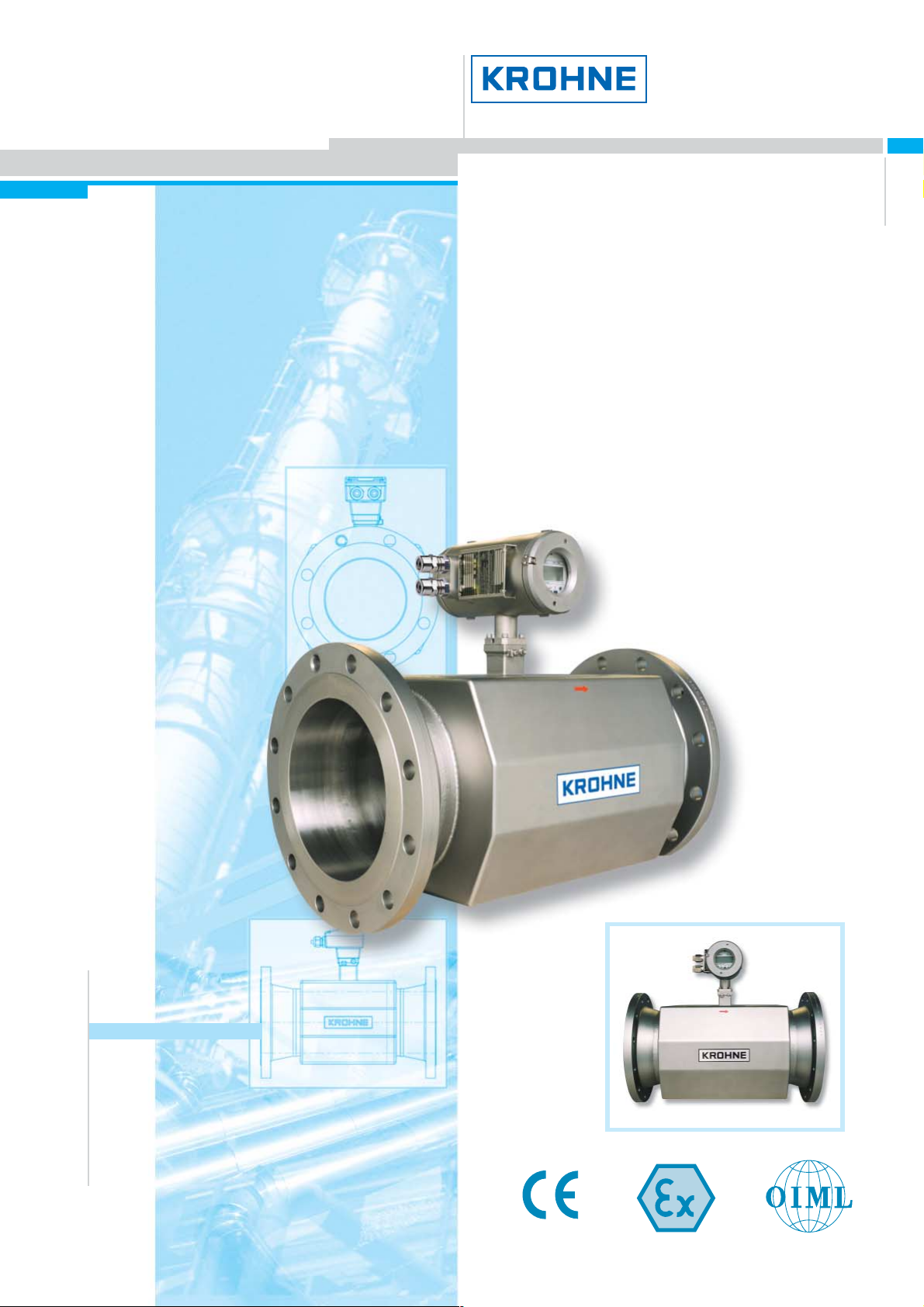
ALTOSONIC III
3-Beam ultrasonic flowmeter
for custody transfer of
liquid hydrocarbons
Designed for custody transfer of light
products
Long-term stability and high reliability
Eliminates maintenance
Non-intrusive
No wear
No pressure loss
Bi-directional
Compliant with OIML R-117, API
Page 2
2ALTOSONIC III
Custody transfer of light
hydrocarbon products
Fiscal metering
Duty metering
(with the ALTOSONIC V as
reference meter)
Allocation metering
Pipeline leak detection
Fields of application
Refineries
Pipeline systems for refined
products
Terminal loading and offloading
of refined products
Truck and rail loading
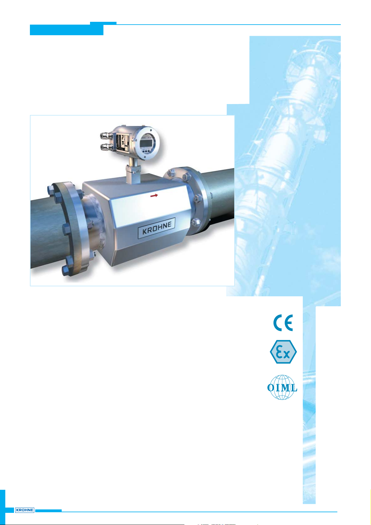
ALTOSONIC III
The flow metering
solution for the oil
and petrochemical
industry
ALTOSONIC III
3-Beam ultrasonic flowmeter for custody transfer
of liquid hydrocarbons
Eliminates maintenance
KROHNE is innovation
The introduction of the ALTOSONIC V, the highly accurate, five-beam liquid ultrasonic
flowmeter in the 1990's for multiple products was a true revolution in the flow market for
custody transfer and master metering.
Over the past years ultrasonic flowmeters have gained full acceptance and have become
the fastest growing flow metering technology in the world. KROHNE's UFM 3030, the first
truly universal and easy to use ultrasonic flowmeter for process applications, created a
breakthrough in the widespread application of ultrasonic flowmeters worldwide.
Introducing ALTOSONIC III
Now, KROHNE is proud to introduce the ALTOSONIC III, an innovative and economical
solution for custody transfer of light oil products. The 3-beam ALTOSONIC III is the outcome
of our revolutionary development of liquid multiple beam ultrasonic flowmeters. It combines
innovative technology with long-term experience to guarantee superior performance at an
attractive price.
KROHNE is experience
The ALTOSONIC III is the result of years of experience in the field with ultrasonic
flowmeters for custody transfer including fiscal metering for a very wide range of
applications.
25 Years ago KROHNE was already one of the pioneers in ultrasonic flow metering. In line
with our vision, we continue to develop and perfect a wide range of single and multiple
beam ultrasonic flowmeters for liquids and gases. Since 1980 over 30,000 KROHNE
ultrasonic flowmeters have been installed showing reliable and trouble-free operation.
KROHNE is quality
It is KROHNE's policy to calibrate each flowmeter that leaves our factory by means of wet
calibration to guarantee the highest possible accuracy and quality. Therefore KROHNE
owns accredited calibration rigs that comply with the most stringent demands (according to
IEC-ISO 17025).
Page 3
ALTOSONIC III
3ALTOSONIC III
A cost effective ultrasonic flowmeter concept for custody transfer
Excellent repeatability
Reliable flow measurement with long-term stability
Large dynamic range: measures from zero flow up to 20 m/s.
Light, compact and robust flowmeter
Bi-directional
Compliant with OIML R-117 and API
Integrated diagnostics
ALTOSONIC III
The alternative for conventional flowmeters
The ALTOSONIC III offers decisive advantage over mechanical flowmeters
like turbine meters and PD meters.
No obstructions in the pipeline
ALTOSONIC III has no parts protruding the flow, in other words no
risks of flow obstruction or blockage.
No moving parts
ALTOSONIC III has not a single internal moving part that can break
down or suffer neither from wear caused by corrosive or abrasive
fluids, gas and solids or from build-up like wax. This means maintenance-free and excellent long term stability.
No filters
For ALTOSONIC III filters are not required, which results in costs
savings on regular inspection, maintenance and cleaning of filters
and no additional pressure drop.
Low pressure drop
Unrestricted flow means no loss of pressure. Reducing pressure drop
means smaller pump capacity, improved pipeline efficiency, and
savings on energy costs.
Minimal maintenance
and substantial savings in cost of ownership.
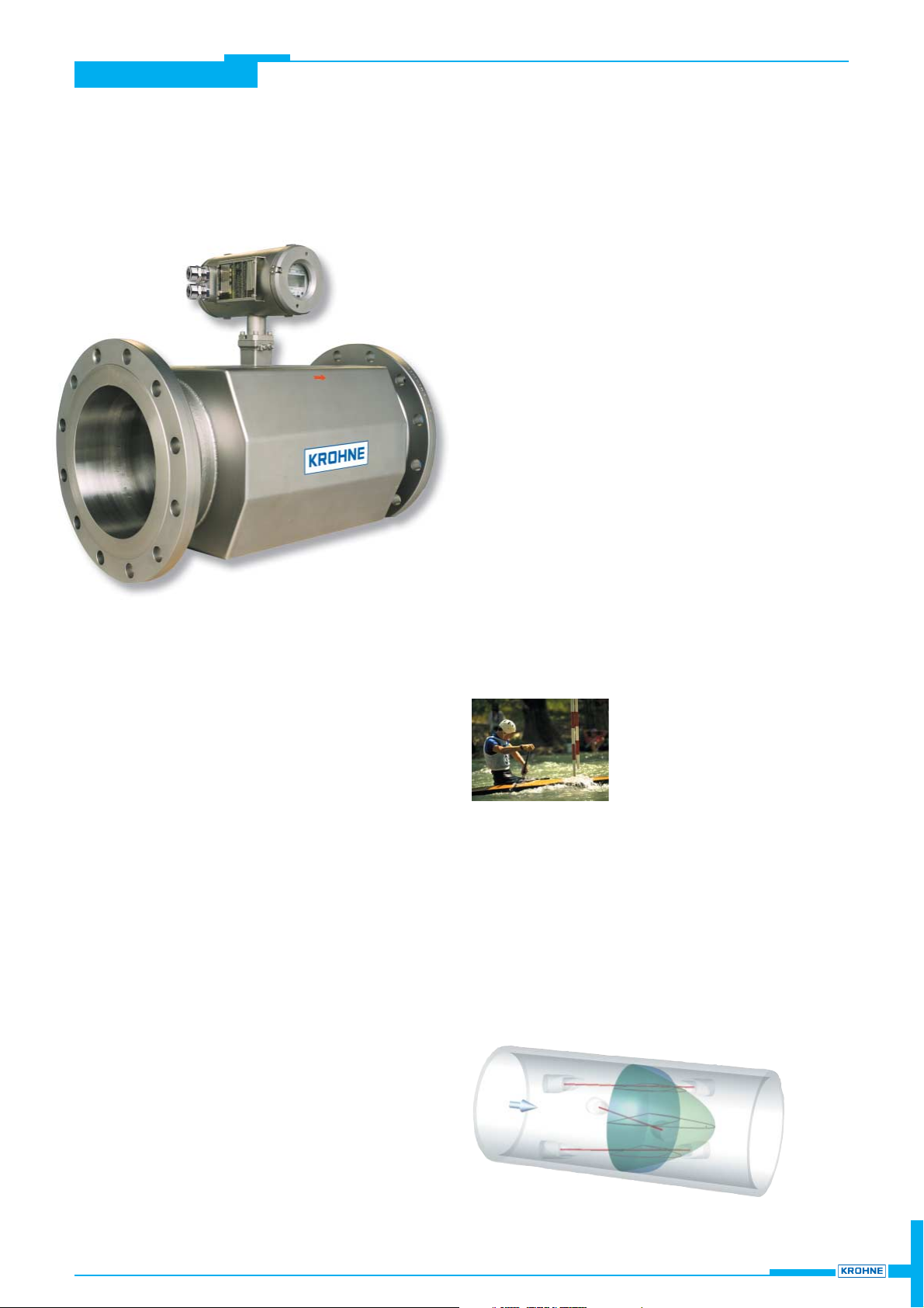
Multi-channel ultrasonic flow measurement
Like all KROHNE ultrasonic flowmeters,
ALTOSONIC III operates by the transit-time
differential method. The measurement principle
is based on a simple physical principle. Imagine
two canoes crossing a river diagonally, one with
the flow and one against the flow. Naturally the
canoe that is travelling with the flow will reach the opposite side sooner than
the canoe that is travelling upstream. Acoustic signals behave in a comparable
way.
By means of patented ultrasonic transducers, the transit time of acoustic
signals that travel upstream and downstream are measured. The difference in
transit time is proportional to the mean liquid flow velocity and is transformed
into an output signal and display of volumetric liquid flow rates.
The 3 measuring beams of the ALTOSONIC III make a 3-dimensional crosssection of the velocity distribution, or flow profile of the medium that flows
through the flow sensor. These measuring beams are positioned such that the
influence of the flow profile is strongly reduced.
ALTOSONIC III
eliminates maintenance in flow metering
Page 4
4ALTOSONIC III
The responsibility as to the suitability, intended use and corrosion-resistance of the materials used in
their construction rests solely with the purchaser.
Versions
ALTOSONIC III/C-EEx
UFS-III/F-EEx
UFC-III/F-EEx
Approvals
Maximum solid particle content < 5% (by v olume)
Maximum gas content < 2% (by v olume)
OIML R-117 Class 0.3
ANSI/API MPMS 5.8-2004
Performance
Custody transfer
API MPMS Chapter 5 Section 8, M easurement of Liquid H y drocarbons by
Ultrasonic Flowmeters U sing Transit Time Technology
Viscosity
Up to 10 cS t for standard operation. For higher v iscosities contact KROH N E
< 1 mm/s
< ± 0.027% conforms to AP I standard
UFC III C flow converter directly mounted on UFS III C flow sensor
Process conditions
Zero stability
ALTOSONIC III is available in a separate and in a compact v ersion and consists of a UFS III ultrasonic flow sensor combined
with a UFC III ultrasonic flow conv erter to make a complete flowmeter. Both the sensor and conv erter are approv ed for use in
hazardous areas.
Measurement functionality
Measuring range
< ± 0.15% of measured v alue (under reference conditions)
Linearity
ALTOSONIC III C (compact)
ALTOSONIC III F (separate)
Uncertainty
Repeatability
CSA Class I, Div . 1 & 2, G roups A, B, C & D
UFC III F flow converter remotely mounted from UFS III F flow sensor
Standard actual volume
0 to 20 m/s (0 ft/s to 66 ft/s), higher flow v elocities on request
< ± 0.05%
EEx zone 1 (ATEX)
CSA Class II, Div. 1 & 2, Groups E, F & G
II 2 G EEx d [ib] IIC T6 …T3 or II 2 G EEx de [ib] II C T6 … T3
II 2 G EEx ib IIC T6 …T3
II 2 G EEx d [ib] IIC T6
FM Class I, Div . 1 & 2, G roups B, C & D
Standard Optional - On request
ALTOSONIC III Ultrasonic flowmeter
FM
CSA
CSA Class III, Div. 1
FM Class II, Div. 1, Groups E, F & G and Div . 2, Groups F & G
FM Class III, Div. 1 & 2
ALTOSONIC III
min. max. min. max. min. max. min. max.
Compact -25°C 140°C -40°C 70°C Compact -13°F 284°F -40°F 158°F
Separate -25°C 180°C -40°C 70°C Separate -13°F 356°F -40°F 158°F
Process temp.
Ambient temp.
°C
Process temp.
Ambient temp.
°F
Temperature Limits
Page 5

5ALTOSONIC III
2"3"4"6"8"
10"
12"
14"
16"
18"
20"
24"
28"
32"
36"
40"
150 lbs RF
300 lbs RF
600 lbs RF/ RTJ -------
900 lbs RF/ RTJ ---------
Pressure rating according to ASME B16.5 Group 2.3 materials. Other combinations of diameter/pressure class are av ailable on request.
UFS III C (compact)
UFS III F (separate)
Flanges
Measuring tube
Housing
Connection box
Blasted
Offshore paint sy stem, silv er
6 points, 1 point 3 repeats, w ith w ater
According to OIML:
6 points, each point 3 repeats, w ith water
Witnessed calibration
RVA certificate
Calibration with hy drocarbon
Protection category
to IEC 529
IP 67 / IP 66 eq. NEMA 4/4X / 6
M20 x 1,5
1/2" N PT
PF 1/2
5 m / 15 ft
10 m / 30 ft
15 m / 45 ft
20 m / 60 ft
25 m / 75 ft
30 m / 90 ft
For a detailed ov erview , see the dimensions and w eights tables in this datasheet.
UFC III C flow converter directly mounted on UFS III C flow sensor.
UFC III F flow converter remotely mounted from UFS III F flow
Versions
Stainless steel A ISI 316 L (1.4408)
Stainless steel A ISI 316 L (1.4404)
Materials used
Other materials (e.g. Duplex)
available o n req uest
Stainless steel A ISI 316 L (1.4404)
Stainless steel A ISI 316 L (1.4404)
Finish
Other f inishes on request
Ultrasonic flow sensor UFS III
Sensor cable connection
for separate v ersions only
Pressure cl ass
Nominal diameter [inch]
ASME B16.5
ASME B16.47, A
Standard Optional - On request
Sensor cable length
for separate v ersions only
Cable ty pe MR06,
O.D. = 11 mm / 0.43"
Calibration
Calibration options
ALTOSONIC III
The responsibility as to the suitability, intended use and corrosion-resistance of the materials used in
their construction rests solely with the purchaser.
Page 6

6ALTOSONIC III
2"3"4"6"8"
10"
12"
14"
16"
18"
20"
24"
28"
32"
36"
40"
150 lbs RF
300 lbs RF
600 lbs RF/ RTJ -------
900 lbs RF/ RTJ ---------
Silver
Offshore paint sy stem, silv er
Typ ical flowmeter configuration
ASME B16.5
Pressure rating according to AS M E B16.5 G roup 2. 3 materials.
For a detailed ov erv iew , see the dimensions and w eights section of this datasheet.
Standard Optional - On request
Nominal diameter [inch]
ASME B16.47, A
Inlet flow conditioner and outlet section
The flow sensor is deliv ered as standard w ith a 10D inlet flow conditioner. For optimal performance the flow sensor and flow conditioner are calibrated
together. The flow sensor has to be installed w ith a straight outlet section w ith a minimum length of 5D.
Finish*
Other paint systems on request
Materials used
Other materials (e.g. Duplex)
available o n req uest
Pressure cl ass
Carbon steel ASTM A 105 / C arbon steel A S TM A106
Stainless steel A ISI 316 L (1.4404)
Flange / Tube
10D
5D
ALTOSONIC III
Installation
General
For specific information please consult the operating and installation instructions or contact KRO H NE.
Position
The flow meter can be installed in a horizontal or v ertical position. In a horizontal pipeline ensure that
the acoustic channels are alw ay s in the horizontal plane.
Completely filled flow sensor
Install the UFS III ultrasonic flow sensor at a location where it will be completely filled under all
circumstances, including at zero flow v elocity .
Flow conditioning
Standard a 10D inlet section w ith ISO tube bundle flow conditioner must be installed upstream of the
flow meter. A fter the meter a straight outlet section of 5D should be installed.
Zero checking
Zero setting is not required w ith ultrasonic flow meters. For zero checking it is adv ised to install shutoff
valves before or after the flow sensor.
Cavitation
At operation sufficient backpressure is required to prev ent cav itation
Page 7

ALTOSONIC III
7ALTOSONIC III
General
UFC III C (compact) UFC III C flow converter directly mounted on UFS III C flow sensor.
UFC III F (separate) UFC III F flow converter remotely mounted from UFS III F flow sensor.
Materials used Conv erter housing Stainless steel AISI 316 L (1.4408)
Blasted
Offshor e paint system, silv er
Protection category
to IEC 529
IP 67 / IP 66
eq. N EM A 4/4X / 6
Operation
Cover remov ed: All display operations, including changing of settings and parameters can
be done by using the push buttons.
Cover in place: M easured v alues and (error) messages can be v iew ed. Resetting of errors
is still possible using a hand-held bar magnet.
Units
Actual flow rate in liter/s, m3/h, US gall/min or user-defined unit (e.g. U S million gall/day).
English (GB)
English (U S )
German
French
Gal van ic isolation
Time constant
Mains supply 100 – 240 V AC (48-63 Hz) +10% / -15%
Low v oltage supply 24 V (AC or DC ), A C : -10% / +15% , DC : 18 - 35 V
M20 x 1,5
1/2" N PT
PF 1/2
Standard Optional - On request
Ultrasonic flow converter UFC III
All inputs and outputs are galv anically isolated from the power supply , but not from each other
Finish
Other paint systems on request
Versions
Overall functionality /
Measurem ents available
Self diagnostics, e.g. v elocity of sound w ithin range, reliability of received acoustic signal, flow sensor not filled
Errors (flashing display and error code)
0.025 - 99 seconds (programmable in increments of 0.01; 0.1 and 1.0 seconds)
The conv erter has a backlit local display with 3 push buttons.
1st line 8 character 7 segment alphanumeric display and sy mbols for key
acknowledgement
2nd line 10 character, 14 segment text display
3rd line 5 markers to identify display in measuring mode
3-field
LC D
Actual v olume flow rate (continuous measurement) in m3, liters, U S gallons, Bbl or user defined v olume unit per hour,
minute, second, or user defined time unit
Flow direction (forw ard or rev erse)
Velocity of sound in m/s or ft/s, per acoustic channel
Signal attenuation (in dB), per acoustic channel
Low-flow cut-off
Power consumption approx . 10 V A (A C ) or approx. 10 W (DC )
Cut-off activ e value 1 - 19% programmable in increments of 1%
Cut-off de-activ e v alue 2 - 20%
The conv erter is fully digital. M easured v alues are obtained using DSP (Digital Signal Processing) to ensure accurate and
highly repeatable measurements.
Power supply
Local display
Cable connecti on
(for power supply and
signal cables)
Languages
Page 8

ALTOSONIC III
8ALTOSONIC III
Ex-connection (standard)
⊥ Common ground
P1 Pulse, frequency output
P2 Pulse, frequency output
90 or 180 degrees phase shifted from P1
S Status output
I/C 0(4) ... 20mA current output
N / L~ Neutral power supply
L/ L~ Live power supply
SizingElectrical connections
Please refer to the instruction manual in the
Dowload Center of the KROHNE internet site on
www.krohne.com for detailed information on how to
connect signal inputs and outputs.
1 m/ s 10 m/s 1 m/s 10 m/s 1 m/s 10 m/s
3.3 ft/s 30 ft/s 3.3 ft/s 30 ft/s 3.3 ft/s 30 ft/s
(m3/h) (m3/h)
(GPM) (GPM) (BBL/hr) (BBL/hr)
2" 7 73 32 321 46 459
3" 16 164 72 723 103 1033
4" 29 292 129 1285 184 1836
6" 66 657 289 2891 413 4132
8" 117 1167 514 5140 735 7345
10" 182 1824 803 8032 1148 11477
12" 263 2627 1157 11565 1653 16527
14" 358 3575 1574 15742 2249 22495
16" 467 4670 2056 20561 2938 29381
18" 591 5910 2602 26022 3719 37186
20" 730 7297 3213 32126 4591 45908
24" 1051 10507 4626 46261 6611 66108
28" 1430 14301 6297 62967 8998 89980
32" 1868 18679 8224 82243 11752 117525
36" 2364 23641 10409 104088 14874 148742
40" 2919 29186 12850 128504 18363 183632
Nominal
diameter
Choosing the correct size is v ery simple due to the extremely wide range of possible
velocities. Typical flow rates for 1 m/s (3,3 ft/s) and 10 m/s (33 ft/s) are specified in the
attached table. P ending on the application the ALTOS ON I C III has a virtually unlimited
flow v elocity range.
Q = 0 % 0 - 16 mA programmable in increments of 1 mA
Q = 100 % 4 – 20 mA
Connection Passive External v oltage 18 - 24 V DC , load ≤ 680 Ohm, (current limit 22 mA)
Pulse duty cy cle 50%
Connection
Alarm trip point (high and low ) based on actual v olume flow rate
Settings
Connection
Flow direction indication (forw ard or rev erse)
Velocity of Sound (VOS )
Tr ansducer signal amplification
Settings
Function
Dual pulse output, 90° or 180° phase shifted from each other
Pulse/unit (max . 1500Hz) (ex ample: 1000 pulses/barrel)
Pulse per v olumetric unit (m3, liters, U S gallons, Bbl or user defined v olume unit)
Current output
Settings
Function
Actual v olume flow rate (continuous measurement)
Status output
Function
Pulse output
Passive mode connection to electronic counter (EC ). E x ternal v oltage ≤ 19 - 32 V DC / I ≤ 150 mA
Diagnostics alarm path errors, all errors
Flow direction indication (forw ard or rev erse)
Passive mode connection to electronic input. E x ternal v oltage ≤ 19 - 32 VD C / I ≤ 150 mA
On or Off
Outputs
Page 9

ALTOSONIC III
9ALTOSONIC III
Dimensions and weights
78 (3.07)
w
Flow direction
a
j
98 (3.86)
ØDi
h
71 (2.8)
e
Flow direction
a
j
160 (6.3)
ØDi
h
165 (6.5)
e
Ø122 (4.8)
206 (8.11)
w
aDih j ew aDih j ew
2" 290 49.2 180 139 100 150 14 11.42 1. 94 7.09 5.47 3.94 5. 91 31
3" 330 73.7 215 170 130 200 26 12.99 2. 90 8.45 6.69 5.12 7. 87 57
4" 380 97.2 247 190 155 220 33 14.96 3. 83 9.74 7.48 6.10 8. 66 73
6" 440 154.1 301 240 210 270 45 17.32 6. 07 11. 84 9.45 8.27 10.63 99
8" 600 202.7 358 370 260 370 72 23.62 7. 98 14. 09 14. 57 10.24 14.57 159
10" 640 254.5 417 415 315 420 105 25.20 10.02 16.41 16.34 12.40 16. 54 231
12" 710 304.7 480 465 365 470 145 27.95 12.00 18.91 18.31 14.37 18. 50 320
14" 770 336.5 522 495 395 500 179 30.31 13.25 20.53 19.49 15.55 19. 69 395
16" 830 387.3 579 550 445 550 221 32.68 15.25 22.78 21.65 17.52 21. 65 487
18" 900 438.1 623 595 500 600 256 35.43 17.25 24.53 23.43 19.69 23. 62 564
20" 950 484.0 680 645 550 650 335 37.40 19.06 26.78 25.39 21.65 25. 59 739
24" 1080 579. 6 788 745 650 750 500 42.52 22.82 31.03 29. 33 25. 59 29.53 1102
28" 1140 691. 2 896 865 750 870 577 44.88 27.21 35.28 34. 06 29. 53 34.25 1272
32" 1260 792. 8 1014 955 855 960 786 49.61 31. 21 39. 91 37.60 33.66 37.80 1733
36" 1400 884. 4 1118 1055 955 1060 1136 55.12 34.82 44.03 41.54 37.60 41.73 2504
40" 1500 986.0 1230 1150 1055 1150 1359 59.06 38.82 48.41 45.28 41.54 45.28 2996
a = flange to flange
Di = inner diameter
h = height flow sensor
Approx.
weight
in kg*
ANSI 150 lbs
dimensions in mm
Nominal
diameter
For compact (C) v ersion: add 6.4 kg (14.1 lbs).
*Approx. w eight of flow sensor in separate (F) v ersion.
Weight conv erter incl. w allmount separate (F) v ersion: 14 kg (30.9 lbs).
Approx.
weight
in lbs*
ANSI 150 lbs
dimensions in inch
Inner diameters based on schedule standard.
j = length housing
e = height housing
w = width housing
aDi
weight
in kg
aDi
Approx.
weight
in kg
aDi
weight
in lbs
aDi
Approx.
weight
in lbs
2" 508 54.8 8 254 54.8 6 20.00 2.16 17. 6 10. 00 2.16 13
3" 762 77.9 20 381 77.9 13 30.00 3.07 44.1 15.00 3.07 29
4" 1016 104.7 32 508 104.7 18 40.00 4.12 70.5 20.00 4.12 40
6" 1524 158.7 65 762 158.7 31 60.00 6.25 143. 3 30.00 6.25 68
8" 2032 206.3 125 1016 206. 3 60 80.00 8.12 275.6 40. 00 8.12 132
10" 2540 260.2 190 1270 260. 2 89 100.00 10.24 418. 9 50.00 10.24 196
12" 3048 309.6 325 1524 309. 6 141 120. 00 12.19 716.5 60.00 12.19 311
14" 3556 339.8 490 1778 339. 8 197 140. 00 13.38 1080.3 70.00 13.38 434
16" 4064 390.6 560 2032 390. 6 255 160. 00 15.38 1234.6 80.00 15.38 562
18" 4572 441.4 700 2286 441. 4 307 180. 00 17.38 1543.2 90.00 17.38 677
20" 5080 489.0 1080 2540 489.0 431 200.00 19.25 2381.0 100.00 19. 25 950
24" 6096 590.6 1425 3048 590.6 615 240.00 23.25 3141.6 120.00 23. 25 1356
28" 7112 695.4 1725 3556 695.4 766 280.00 27.38 3803.0 140.00 27. 38 1689
32" 8128 797.0 2400 4064 797.0 1054 320.00 31.38 5291. 1 160.00 31. 38 2324
36" 9144 898.6 3055 4572 898.6 1338 360.00 35.38 6735. 2 180.00 35. 38 2950
40" 10160 996. 0 4235 5080 996.0 1895 400.00 39. 21 9336. 6 200.00 39. 21 4178
Nominal
diameter
ANSI 150 lbs
dimensions in inch
ANSI 150 lbs
dimensions in mm
10D inlet spoolpiece
5D outlet spoolpiece
10D inlet spoolpiece
5D outlet spoolpiece
Dimensions in mm (inch)
Page 10

ALTOSONIC III
10 ALTOSONIC III
Dimensions and weights
aDih j ew aDih j ew
2" 300 49.2 185 139 100 150 15 11.81 1.94 7. 28 5.47 3. 94 5.91 33
3" 350 73.7 224 170 130 200 30 13.78 2.90 8. 83 6.69 5. 12 7.87 66
4" 400 97.2 260 190 155 220 42 15.75 3.83 10.24 7. 48 6.10 8.66 93
6" 470 146.4 320 240 210 270 69 18.50 5.76 12.59 9. 45 8.27 10.63 152
8" 620 193.7 377 370 260 370 115 24.41 7.63 14.84 14.57 10.24 14.57 254
10" 670 247.6 436 415 315 420 156 26.38 9.75 17.16 16.34 12.40 16.54 344
12" 750 298.4 499 465 365 470 213 29.53 11.75 19.66 18.31 14.37 18.50 470
14" 810 325.6 547 495 395 500 290 31.89 12.82 21.53 19.49 15.55 19.69 639
16" 870 376.4 604 550 445 550 358 34.25 14.82 23.78 21.65 17.52 21.65 789
18" 940 417.2 661 595 500 600 482 37.01 16.43 26.03 23.43 19.69 23.62 1063
20" 1000 468.0 718 645 550 650 578 39.37 18. 43 28. 28 25. 39 21.65 25.59 1274
24" 1110 569.6 839 745 650 750 811 43.70 22. 43 33. 03 29. 33 25.59 29.53 1788
28" 1300 661.2 950 865 750 870 1223 51.18 26.03 37.41 34. 06 29. 53 34.25 2696
32" 1440 752.8 1058 955 855 960 1714 56.69 29.64 41.66 37.60 33.66 37.80 3779
36" 1580 854.4 1169 1055 955 1060 2131 62.20 33.64 46. 03 41. 54 37.60 41.73 4698
40" 1580 946.0 1204 1150 1055 1150 2100 62.20 37.24 47.41 45. 28 41.54 45.28 4630
Inner diameters based on schedule standard.
*Approx . w eight of flow sensor in separate (F) v ersion.
j = length housing
w = width housing
e = height housing
a = flange to flange
Di = inner diameter
h = height flow sensor
Nominal
diameter
For compact (C) v ersion: add 6. 4 kg (14.1 lbs).
Weight conv erter incl. w allmount separate (F) v ersion: 14 kg (30.9 lbs).
Approx.
weight
in lbs*
Approx.
weight
in kg*
ANSI 300 lbs
dimensions in mm
ANSI 300 lbs
dimensions in inch
aDi
weight
in kg
aDi
weight
in kg
aDi
weight
in lbs
aDi
weight
in lbs
2" 508 53.9 10 254 53.9 7 20.00 2.12 22.0 10.00 2.12 15
3" 762 77.9 24 381 77.9 16 30.00 3.07 52.9 15.00 3.07 35
4" 1016 104.7 40 508 104.7 26 40.00 4.12 88.2 20.00 4.12 57
6" 1524 154.1 95 762 154.1 54 60.00 6.07 209. 4 30.00 6.07 119
8" 2032 206.4 150 1016 206. 4 84 80.00 8. 13 330. 7 40.00 8.13 185
10" 2540 257.4 250 1270 257. 4 137 100.00 10.13 551. 2 50. 00 10.13 302
12" 3048 307.0 390 1524 307. 0 204 120.00 12.09 859. 8 60. 00 12.09 450
14" 3556 339.8 500 1778 339. 8 270 140.00 13.38 1102.3 70.00 13.38 595
16" 4064 387.3 710 2032 387. 3 376 160.00 15.25 1565.3 80.00 15.25 829
18" 4572 434.9 1000 2286 434.9 509 180.00 17.12 2204.6 90.00 17.12 1122
20" 5080 482.6 1280 2540 482.6 672 200.00 19.00 2821.9 100.00 19. 00 1482
24" 6096 581.1 2065 3048 581.1 1047 240.00 22. 88 4552. 6 120.00 22. 88 2308
28" 7112 679.4 3023 3556 679.4 1543 280.00 26. 75 6664. 6 140.00 26. 75 3402
32" 8128 781.0 3995 4064 781.0 2035 320.00 30. 75 8807. 5 160.00 30. 75 4486
36" 9144 876.3 5635 4572 876.3 2877 360.00 34. 50 12423.1 180. 00 34.50 6343
40" 10160 976. 0 6665 5080 976.0 3103 400.00 38.43 14693.9 200.00 38. 43 6841
Nominal size
ANSI 300 lbs
dimensions in inch
ANSI 300 lbs
dimensions in mm
10D inlet spoolpiece
5D outlet spoolpiece
10D inlet spoolpiece
5D outlet spoolpiece
Page 11

ALTOSONIC III
11ALTOSONIC III
aDih j ew aDih j ew
2" 320 49.2 185 139 100 150 17 12.60 1. 94 7.28 5.47 3. 94 5.91 37
3" 370 73.7 224 170 130 200 33 14.57 2. 90 8.83 6.69 5. 12 7.87 73
4" 440 97.2 270 190 155 220 53 17.32 3. 83 10. 62 7.48 6.10 8. 66 117
6" 530 131.8 339 240 210 270 111 20. 87 5.19 13.34 9.45 8.27 10.63 245
8" 660 189.1 396 370 260 370 165 25. 98 7.44 15.59 14. 57 10.24 14.57 364
10" 770 233.0 468 415 315 420 272 30. 31 9.17 18.41 16. 34 12.40 16.54 600
12" 830 273.8 518 465 365 470 359 32. 68 10. 78 20.41 18.31 14.37 18.50 791
14" 880 305.6 556 495 395 500 423 34. 65 12. 03 21.91 19.49 15.55 19.69 933
16" 960 346.4 623 550 445 550 603 37. 80 13. 64 24.53 21.65 17.52 21.65 1329
Approx.
weight
in lbs*
Approx.
weight
in kg*
ANSI 600 lbs
dimensions in mm
ANSI 600 lbs
dimensions in inch
Nominal
diameter
aDi
weight
in kg
aDi
weight
in kg
aDi
weight
in lbs
aDi
weight
in lbs
2" 508 52.5 11 254 52.5 9 20. 00 2.07 24.3 10.00 2.07 20
3" 762 77.9 26 381 77.9 19 30.00 3.07 57.3 15.00 3.07 42
4" 1016 102.3 55 508 102.3 38 40.00 4.03 121.3 20.00 4.03 84
6" 1524 146.4 140 762 146.4 92 60. 00 5.76 308. 6 30.00 5.76 203
8" 2032 193.7 250 1016 193. 7 154 80.00 7.63 551.2 40. 00 7.63 340
10" 2540 242.8 445 1270 242. 8 268 100.00 9.56 981.1 50.00 9.56 591
12" 3048 295.3 570 1524 295. 3 339 120.00 11.62 1256.6 60.00 11.62 747
14" 3556 325.4 760 1778 325. 4 432 140.00 12.81 1675.5 70.00 12.81 952
16" 4064 373.1 1105 2032 373.1 618 160. 00 14.69 2436.1 80.00 14.69 1362
ANSI 600 lbs
dimensions in inch
ANSI 600 lbs
dimensions in mm
10D inlet spoolpiece
5D outlet spoolpiece
10D inlet spoolpiece
5D outlet spoolpiece
Nominal
diameter
a Di h j e w a Di h j e w
2" 380 49.2 210 139 100 150 27 14.96 1. 94 8.27 5.47 3. 94 5.91 60
3" 420 66.7 240 170 130 200 46 16.54 2. 63 9.45 6.69 5. 12 7.87 101
4" 470 87.3 279 190 155 220 69 18.50 3. 44 10. 99 7.48 6.10 8. 66 152
6" 570 131.8 352 240 210 270 138 22. 44 5.19 13.84 9.45 8.27 10.63 304
8" 750 169.1 422 370 260 370 256 29. 53 6.66 16.59 14. 57 10.24 14.57 564
10" 840 213.0 487 415 315 420 385 33. 07 8.39 19.16 16. 34 12.40 16.54 849
12" 920 263.8 544 465 365 470 507 36. 22 10. 39 21.41 18.31 14.37 18.50 1118
Nominal
diameter
Approx.
weight
in lbs*
Approx.
weight
in kg*
ANSI 900 lbs
dimensions in mm
ANSI 900 lbs
dimensions in inch
aDi
weight
in kg
aDi
weight
in kg
aDi
weight
in lbs
aDi
weight
in lbs
2" 508 49.3 22 254 49.3 19 20.00 1.94 48.5 10.00 1.94 42
3" 762 73.7 40 381 73.7 30 30.00 2.90 88.2 15.00 2.90 66
4" 1016 97.2 70 508 97. 2 51 40.00 3.83 154.3 20.00 3.83 112
6" 1524 146.4 165 762 146.4 116 60.00 5.76 363.8 30.00 5.76 256
8" 2032 182.6 350 1016 182.6 231 80.00 7.19 771. 6 40.00 7.19 509
10" 2540 230.2 580 1270 230.2 371 100. 00 9.06 1278.7 50.00 9.06 818
12" 3048 280.9 815 1524 280.9 514 120. 00 11. 06 1796.8 60.00 11.06 1133
Nominal
diameter
ANSI 900 lbs
dimensions in inch
ANSI 900 lbs
dimensions in mm
10D inlet spoolpiece
5D outlet spoolpiece
10D inlet spoolpiece
5D outlet spoolpiece
 Loading...