

Page 1
CMD
©
KROHNE 07/2005 7.30950.31.00
Variable area flowmeters
Vortex flowmeters
Flow controllers
Electromagnetic flowmeters
Ultrasonic flowmeters
Mass flowmeters
Level measuring instruments
Communications technology
Engineering systems & solutions
Switches, counters, displays and recorders
Heat metering
Pressure and temperature
Installation and
operating instructions
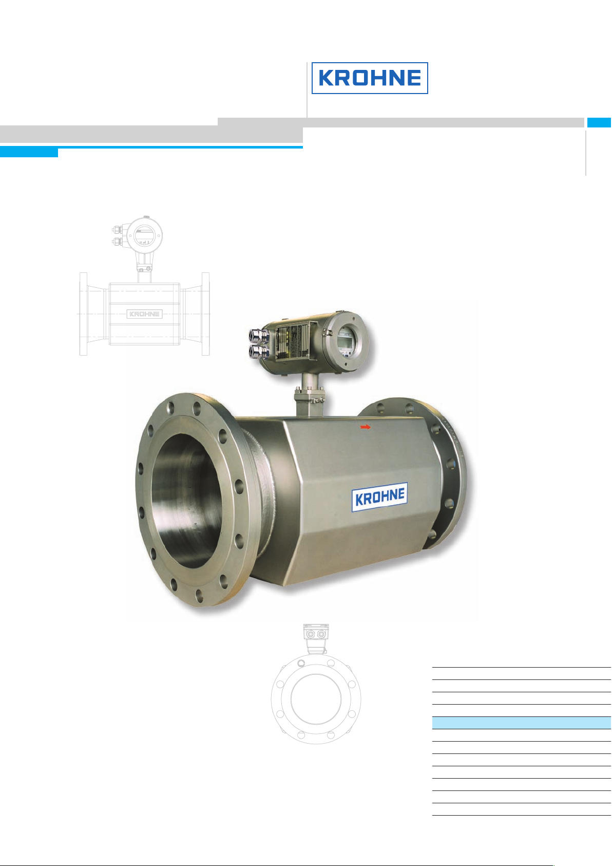
ALTOSONIC III
3-beam ultrasonic flowmeters
for custody transfer
of liquid hydrocarbons
UFC III F/...EEx ultrasonic flow converter
UFS III F/...EEx ultrasonic flow sensor
Subject to change without notice.
●●
Long term stability; high reliability
●●
Eliminates maintenance
●●
Non-intrusive
●●
No wear
●●
No pressure loss
●●
Bi-directional
●●
Compliant with OIML R-117, API
Page 2
General advice on safety
• Do not install, operate or maintain this flowmeter without reading, understanding and following the factory-supplied
instructions, otherwise injury or damage may result.
• Read these instructions carefully before starting installation and save them for future reference.
• Observe all warnings and instructions marked on the product.
• Use only mains supply with protective earthing connected.
• Do not use the product with removed covers under wet conditions.
• Consider handling and lifting instructions to avoid damage.
• Install the product securely and stable.
• Install and connect cabling proper to exclude damage or harmful situations.
• If the product does not operate normally, refer to the service instructions or refer to qualified KROHNE service
engineers. There are no operator-serviceable parts inside the product.
The following symbols may appear in this manual or on the product.
Attention: Refer to operating and installation instructions!
Disclaimer
Product liability
and warranty
Items included with order
Danger: Risk of electric shock!
Protective Earth (PE) conductor terminal!
These terms may appear in this manual or on the instrument:
Warning statement: Identify conditions or practice that could result in injury or loss of life.
or
Caution statement: Identify conditions or practice that could result in damage to the instrument or other property.
• This document contains important information on the instrument. KROHNE attempts to be as accurate and up-to-
date as possible but assumes no responsibility for errors or omissions. Nor does KROHNE make any commitment
to update the information contained herein. This manual and all other documents are subject to change without
prior notice.
• KROHNE will not be liable for any damage of any kind by using its instrument, including, but not limited to direct,
indirect, incidental, punitive and consequential damages.
• This disclaimer does not apply in case KROHNE has acted on purpose or with gross negligence. In the event any
applicable law does not allow such limitations on implied warranties or the exclusion of limitation of certain
damages, you may, if such law applies to you, not be subject to some or all of the above disclaimer, exclusions or
limitations.
• Any instrument purchased from KROHNE is warranted in accordance with the relevant product documentation and
our Terms and Conditions of Sale.
• KROHNE reserves the right to alter the content of its documents, including this disclaimer in any way, at any time,
for any reason, without prior notification, and will not be liable in any way for possible consequences of such
changes.
• Responsibility for suitability and intended use of this ultrasonic flowmeter rests solely with the user. Improper
installation and operation of the flowmeter (syste m) may lead to loss of warranty.
• In addition, the Terms and Conditions of Sale are applicable and are the basis for the purchase contract.
• If flowmeters need to be returned to KROHNE, please note the information given on the last pages of the
installation and operating instructions. KROHNE regrets that they cannot repair or check flowmeter(s) unless
accompanied by the completed form (see last pages of the installation and operating instructions).
• ALTOSONIC III ultrasonic flowmeter, consisting of a flow sensor (UFS III) and a flow converter (UFC III) either built
together as a compact system or supplied as two separate pieces, in the size as indicated on the packaging box.
• Signal cable (only in case of a separate system).
• Special tool for opening the converter housing.
ALTOSONIC III 2
Page 3
Installation and operating instructions
Documentation supplied
• Handbook; manual and installation and operation instructions
• Approval documents and certificates
• Report of factory settings of the flow converter
• Certificate of flowmeter calibration data
This instrument is developed and manufactured by:
KROHNE Altometer
Kerkeplaat 12
3313 LC Dordrecht
The Netherlands
For information, maintenance or service, please contact your nearest local KROHNE representative.
See www.krohne.com.
WARNING!
No changes may be made to the devices. Unauthorized changes might affect the explosion safety of the devices.
Be sure to follow these instructions!
IMPORTANT!
• The prescriptions and regulations as well as the electrical data described in the EC type examination certificate
must be obeyed.
• Beside the instructions for electrical installations in non-hazardous locations according to the applicable national
standard (equivalent of HD 384 or IEC 364, e.g. VDE 0100), especially the regulations in EN 60079-14 "Electrical
installations in hazardous locations" or equivalent national standard (e.g. DIN VDE 0165 Part 1) must be strictly
followed.
• Installation, establishment, utilization and maintenance are only allowed to be executed by personnel with an
education in explosion safety!
WARNING!
When removing the front or rear cover of the converter any sealing will be broken.
3 ALTOSONIC III
Page 4

Table of contents
1. Introduction.....................................................................................................................................................5
1.1 Cautions................................................................................................................................................................................................................ 5
1.2 Unpacking and inspection.................................................................................................................................................................................. 5
1.3 System description.............................................................................................................................................................................................. 5
1.4 Approvals.............................................................................................................................................................................................................. 5
2. Mechanical Installation...................................................................................................................................6
2.1 Handling the flowmeter....................................................................................................................................................................................... 6
2.2 Installation location and position....................................................................................................................................................................... 6
2.3 Accessibility and environmental precautions .................................................................................................................................................. 8
2.4 Special installation requirements....................................................................................................................................................................... 8
2.5 Pipe flanges.......................................................................................................................................................................................................... 9
2.6 Pipes with cathodic protection........................................................................................................................................................................... 9
3. Connecting the signal converter..................................................................................................................10
3.1 Safety instructions............................................................................................................................................................................................. 10
3.2 Installation in hazardous areas ........................................................................................................................................................................ 10
3.3 Converter terminal box...................................................................................................................................................................................... 10
3.4 Power supply connection .................................................................................................................................................................................10
3.5 Connection of sensor cables............................................................................................................................................................................ 11
3.6 Electrical connection of the signal inputs and outputs................................................................................................................................. 12
3.7 Connection diagram examples......................................................................................................................................................................... 12
3.8 Start-up ............................................................................................................................................................................................................... 14
3.9 Operating the signal converter......................................................................................................................................................................... 14
3.10 Menu structure and function of operating keys ............................................................................................................................................. 15
3.11 Description of functions.................................................................................................................................................................................... 20
4. Functional checks and service....................................................................................................................26
4.1 Functional checks.............................................................................................................................................................................................. 26
4.2 Device information............................................................................................................................................................................................. 26
4.3 Measuring zero flow value................................................................................................................................................................................ 26
5. Installation in hazardous areas, zone 1 and zone 2 ...................................................................................27
5.1 Approvals............................................................................................................................................................................................................ 27
5.2 Compact flowmeter............................................................................................................................................................................................ 27
5.3 Flow sensor........................................................................................................................................................................................................ 27
5.4 Flow converter.................................................................................................................................................................................................... 28
5.5 Technical data.................................................................................................................................................................................................... 29
6. Electrical installation....................................................................................................................................30
6.1 General................................................................................................................................................................................................................ 30
6.2 Connecting cables............................................................................................................................................................................................. 30
6.3 Connection diagrams........................................................................................................................................................................................ 30
7. Service and maintenance.............................................................................................................................33
7.1 Introduction........................................................................................................................................................................................................ 33
7.2 Replacement of electronics unit or power fuse(s) ......................................................................................................................................... 33
7.3 Replacement of electronics unit....................................................................................................................................................................... 34
7.4 Replacement of mains fuse .............................................................................................................................................................................. 34
7.5 Returning the flowmeter to KROHNE for service or repair............................................................................................................................ 35
ALTOSONIC III 4
Page 5
Installation and operating instructions
1. Introduction
1.1 Cautions
For flowmeters supplied with a voltage over 50 V AC:
• Refer all maintenance or service to trained KROHNE service engineers.
• Mains power shall be disconnected from the product before performing any maintenance.
• This product is prepared for and can only function with the rated AC mains or DC supply voltage as indicated on
the type plate.
For 100 – 240 V AC supplied flowmeters:
• This product is a Class 1 device (earthed) and requires a correct connection to protective earth. The protective
earth conductor of the main power shall be properly connected to the marked protective earth terminal to ensure
safety from electric shock for the operator and its environment.
1.2 Unpacking and
inspection
• The product has been thoroughly inspected and tested before shipment and is ready for operation.
• After carefully unpacking, inspect for shipping damage before attempting to operate. If any indication of mechanical
damage is found, immediately contact the responsible transport service and your local KROHNE representative.
• A simple operating check of the electronics after unpacking and before permanent installation is advisable to
ascertain whether it has suffered damage during shipment.
• Confirm for the correct mains voltage printed on the type plate. If it differs from the ordered product please contact
your local KROHNE representative.
• After connecting to the mains, check if there is any indication on the display and if the backlight of the display is
lighted. If not, contact your local KROHNE representative.
1.3 System description
The ALTOSONIC III ultrasonic flowmeter is a precision instrument designed for linear, bi-directional flow measurement
of liquids. Flow measurement values can be outputted via the standard analog and-or pulse/frequency outputs. Via a
user friendly operator interface (HMI) the flow can be read. Next to actual volumetric flow measurement the converter
can be configured to perform measurement and output of the liquid sonic velocity and acoustic signal attenuation.
1.4 Approvals
CE Approvals
EMC, Electromagnetic Compatibility Directive
EMC directive 89/336/EEC.
Low Voltage Directive
73/23/EEC and is designed in accordance with EN IEC 61010-1 first and second edition.
Pressure Equipment Directive 97/23/EC / Module H
The KROHNE organization complies with the requirements of Module H of the Pressure Equipment Directive 97/23/EC
(full quality assurance).
ATEX directive ATEX Directive 94/9/EC
Both the flow sensor and the flow converter are in compliance with the European Directive 94/9 EG (i.e. ATEX 100A).
5 ALTOSONIC III
Page 6
2. Mechanical
Installation
2.1 Handling the
flowmeter
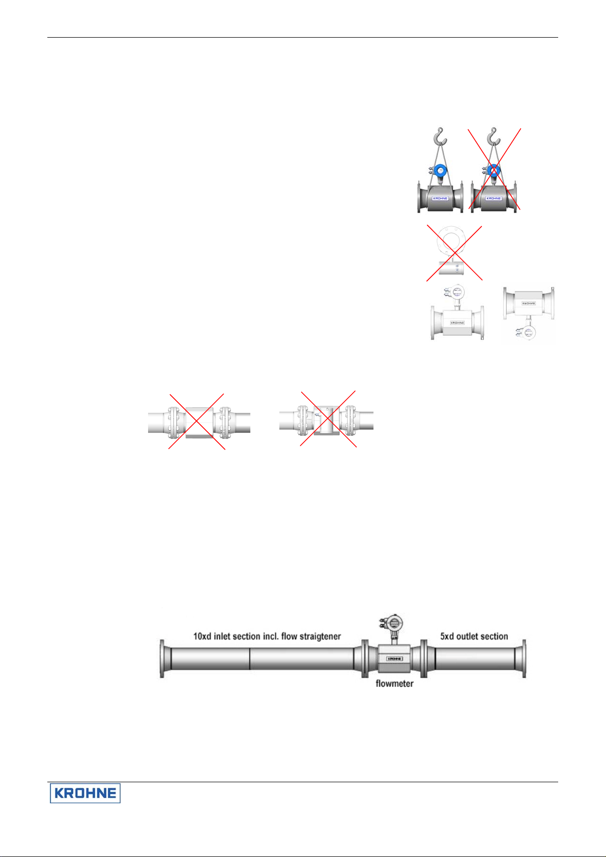
Important: Do not lift the flowmeter by the signal converter housing or the
terminal box. Check the weight of the flowmeter as indicated on the type
plate before handling the unit. When handling the flowmeter avoid hard
blows, jolts or impacts.
2.2 Installation location
and position
Do not place the flowmeter on the signal converter housing.
As the ALTOSONIC III is used in hydrocarbon pipelines, be aware of
potentially explosive atmospheres. Local standards and regulations must be
respected.
The flow sensor must be completely filled at all times for proper flow
measurement. Non-wetted sensors show loss of signal. There is no damage
when this occurs.
The sensor must be installed in a horizontal or vertical position. A correct
position of the unit guarantees a completely filled flow sensor and accurate
flow measurement.
Inlet and outlet sections
For functioning within stated accuracy the flow sensor has to be installed with specified inlet flow conditioner and outlet
sections. The flow conditioner is delivered as a part of the flowmeter as the flow sensor and flow conditioner are calibrated
together for optimal performance.
Inlet configurations (upstream): Straight inlet section, length 10 D with ISO tube bundle flow conditioner.
Outlet configuration (downstream): Straight outlet section, length 5 D.
D = nominal diameter of the flow sensor.
It is advised to keep length of 5 D straight pipe section upstream between flow conditioner and upstream disturbances.
ALTOSONIC III 6
Bush guides
Every ALTOSONIC III is calibrated in combination with a dedicated inlet flow
conditioner. To minimize the installation effects on the performance of the
ALTOSONIC III a provision is made to assure that the flow conditioner
versus the ALTOSONIC III have the same position at operation as during the
initial calibration.
Page 7
Installation and operating instructions
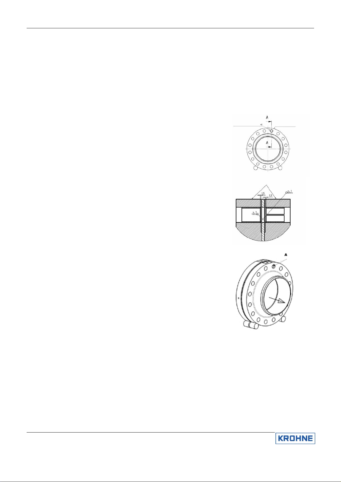
During the mechanical installation of the ALTOSONIC III and the flow
conditioner it is absolutely required that both parts are aligned with high
accuracy.
“Bush Guides” are permanently welded in one of the top bolt holes of the
inlet flange of the ALTOSONIC III and the outlet flange of the flow
conditioner. The position of these “Bush Guides” is marked on the flange
with “BG”. This provision is integrated to assure the position and to align the
ALTOSONIC III in combination with the flow conditioner as accurate as
possible. If the ALTOSONIC III is used bi-directionally the outlet flange is
provided with a ”Bush Guide” as well.
Seen upstream, only the right top hole is fitted with a bush guide. When the
flowmeter is bidirectional, both flanges of the flowmeter are fitted with a bush
guide, which are placed collinear.
Mark the location of the bush guide in both flanges
Flow direction
Please note to the forward direction of the flow sensor indicated by the
direction arrow on the body. If the flow has this direction the output indication
will be positive.
Bolts and nuts
Use the specified bolts and nuts and gaskets, according to the ordered
flange type and pressure rating and mount according the general or local
requirement.
Vibration
Do not expose the sensor unit to intensive vibrations. Support of the flow
sensor is only allowed at the in- and outlet sections near the flowmeter.
7 ALTOSONIC III
Page 8

2.3 Accessibility and
environmental
precautions
2.4 Special installation
requirements
Gas inclusion
To avoid measuring errors due to gas inclusion, adequate measures have to
be taken. Gas inclusion should be limited to the lowest possible value and
shall be < 1 vol. % according to OIML R117 for accurate measuring.
Particle inclusion
To avoid measuring errors due to particle inclusion, adequate measures
have to be taken. Particle inclusion should be limited to the lowest possible
value and shall be < 5 % for accurate measurement.
Cavitation
In order to prevent cavitation in the following formula should be applied to
calculate the minimum required back pressure:
Pb ≥ 2.65 10E-5 ρL* vL
Pb Back pressure [bar]
ρL Liquid density [kg/m3]
vL Liquid velocity [m/s]
Pv Vapour pressure [bar] (at operational temperature)
If required the position of the signal converter can be modified by turning the
display through 90° or 180°.
In case of direct sunlight, we recommend installation of a sunshield to
prolong the life of the meter. No direct damage will occur without a sunshield.
Do not expose the signal converter to excessive vibration. For this, support
the pipeline on either side of the flowmeter.
Ambient temperature: -40°C to +70°C/ -40°F to +158°F
Product temperature: -25°C to +180°C/ -13°F to +356°F
Storage temperature: -40°C to +80°C/ -40°F to +176°F
Keep a minimum distance between pipe centerline and adjacen t wall of at
least 0.5 m (1.6 ft).
To avoid measuring errors and malfunctioning of the flowmeter due to gas or
air inclusions or an empty pipe, please observe the following precautions:
Since gas will collect at the highest point of a pipe, installation of the
flowmeter at that location should be avoided at all times. Also installation in a
down going pipe should be avoided since a completely filled pipe may no t be
guaranteed due to cascading affects. Additionally flow profile distortion is
possible.
2
+ 1.25 Pv
Long horizontal pipes
Install in slightly ascending pipe section. If not possible, ensure adequate
velocity to prevent air, gas or vapor from collecting in upper part of flow tube
As a partially filled meter will report higher than actual flow rates, or not
measure (as transducer pairs become non-wetted).
Mixing different fluid products
Install the flowmeter upstream of mixing point or at minimum distance of 30
D (D = flowmeter diameter) downstream of the mixing point, otherwise the
flow measurement may be unstable.
ALTOSONIC III 8
Page 9
2.5 Pipe flanges
Installation and operating instructions
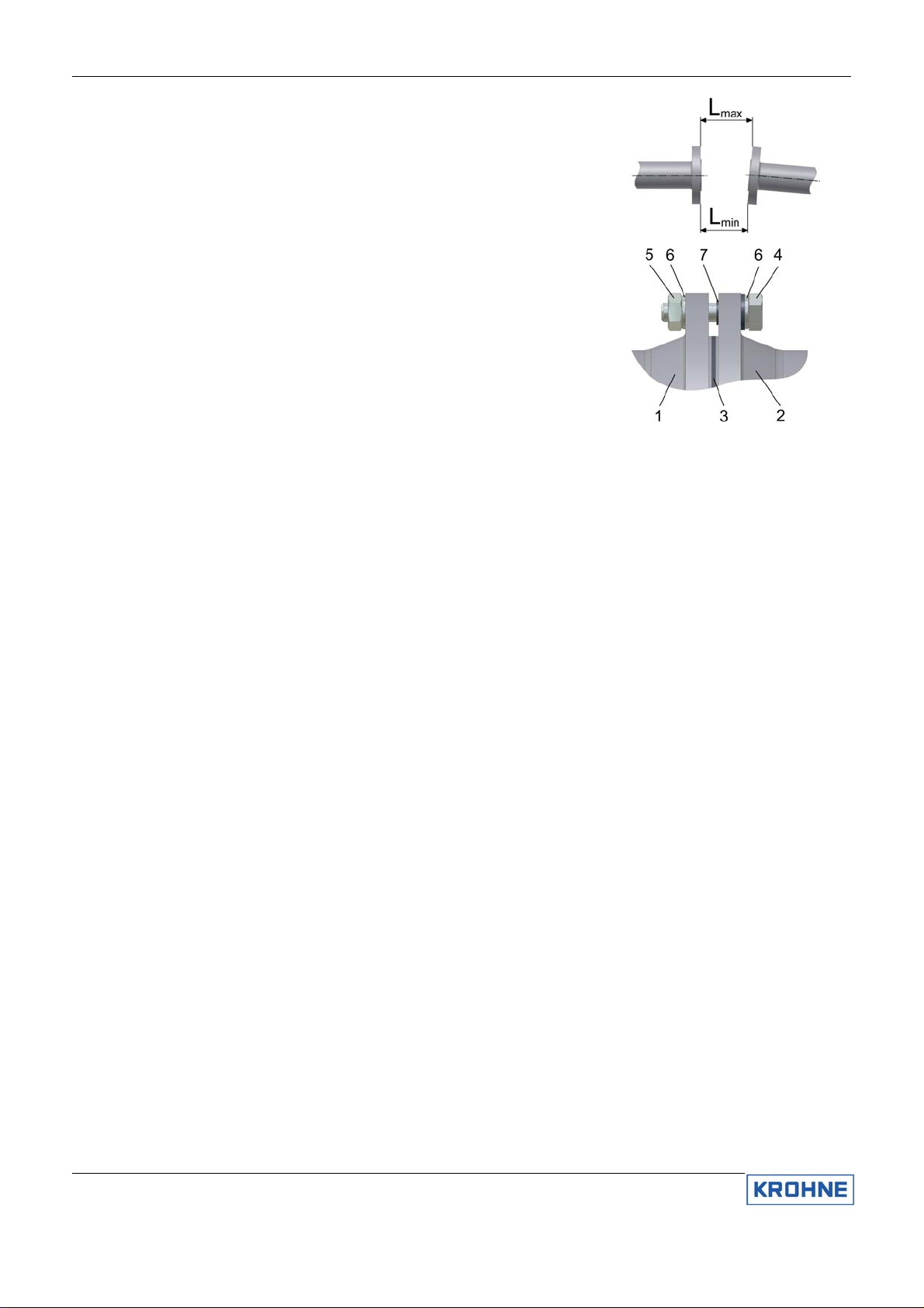
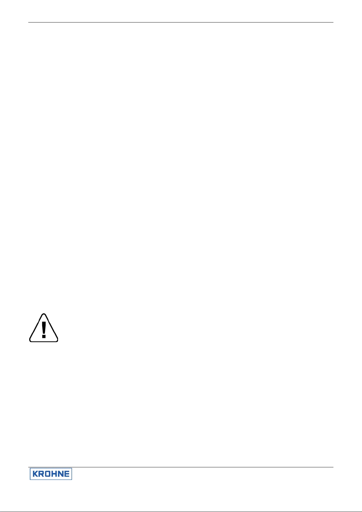
Refer to dimensional drawings for flange spacing and in addition allow for
thickness of gaskets. Install flowmeter in line with pipe axis. Pipe flange
faces must be parallel to each other, max.
Permissible deviation: Lmax - Lmin ≤ 0.5 mm (0.02").
2.6 Pipes with cathodic
protection
Pipes with electric corrosion protection
are generally insulated inside and
outside so that the fluid has no
conductive connection to ground. The
flowmeter must be insulated from the
pipe. Note the following when installing
the flowmeter:
The pipe flanges must be connected to
each other using a copper cable (L), but
must not be connected to the flowmeter.
The bolts for the flange connections and
the gaskets must be insulated. Use
sleeves and washers that are made of
insulating material (these must be
provided by customer).
Follow grounding instructions.
Use ≥ 4 mm² (≥ AWG 11 cable).
Note: No earthing cables are supplied by KROHNE.
1. Flange of flow sensor
2. Pipe flange
3. Gasket
4. Bolt
5. Nut
6. Washer
7. Insulating sleeve
9 ALTOSONIC III
Page 10
3. Connecting
the signal
converter
3.1 Safety
instructions
3.2 Installation in
hazardous
areas
3.3 Converter
terminal box
3.4 Power supply
connection
This product is designed for use in accordance with EN IEC 61010-1 for Installation Category 2 and Pollution Degree 2.
Hazardous voltages are present within this product during normal operation.
The product is designed for Protection Class I and should never be operated without protective earthing.
The product shall also never be operated with covers removed unless equivalent protection of the operator and its environment
from accidental contact with hazardous internal voltages is provided. Always follow basic and local safety precautions when
using this product to reduce risk of injury from electrical shock, spread of fire or other dangerous situations.
All ultrasonic flowmeters of the ALTOSONIC III series must always be incorporated within the equipotential bonding system of
the hazardous area. For this purpose it is provided with an external PE-terminal. The external PE-terminal is located on the
connecting flange at the bottom of the flow converter housing and on top of the support of the flow sensor, just below the junction
box.
A separate bonding conductor must be at least 4 mm
Clause 413 of HD 384.4.41 or IEC 364-4-41. Make sure that the core of the bonding wire is properly mounted under the U-clamp
of the PE-terminal and that the screw is tightly fixed.
• The converter terminal box is accessible after removing the rear (blind) cover of the electronics section using the special
wrench supplied with the flowmeter.
• Do not damage the screw thread and the gasket, never allow dirt to accumulate, and make sure that the screw thread is well
greased, using Teflon grease at all times. A damaged gasket must be replaced immediately!
• Do not cross or loop the cables in the terminal box of the signal converter. Use separate cable entries for power supply and
signal cables.
Environmental conditions
The ALTOSONIC III is designed to operate safely under the following conditions:
• Suitable for indoor and outdoor use, the instrument is usable up to protection category IP 67 (IEC 60529).
• Use up to an altitude of 2000 m above sees.
• Suitable for an operation ambient temperature range: - 40°C to +70°C / - 40°F to +158°F.
• Suitable for an storage temperature range: -40°C to + 80°C / -40°F to + 176°F.
• Suitable for use in atmospheres with a relative humidity up to 80%.
• Mains supply voltage fluctuations up to -15 and +10% of the specified voltage range.
• Over voltages up to category II on the main supply voltage (IEC 60364-4-443).
• Connected to protective earth conductor (Protection Class I).
• Rated pollution degree 2.
• This instrument is intended for permanent connection to the mains. It is required (for example for service) to mount an
external switch or circuit breaker near the product for disconnection from the mains. It must be easily reachable by the
operator and marked as the disconnecting device for this product. The switch or circuit breaker has to be suitable for the
application and shall also be in accordance with to local (safety) requirements and of the building installation (IEC 60947-1/-
3).
• The protective conductor clamp terminal size M5, press-fitted in the terminal compartment (near the main connection
terminals), shall always to be connected to the protective earth conductor of the mains supply. Conductors up to 4 mm² (11
AWG) be connected to this terminal. The diameter of the conductors of the mains supply, including the protective earth
conductor shall be in accordance with the general and local requirements.
• It is not allowed to use the protective conductor terminal for any other connection than the protective earth conductor.
• IP 67 is only warranted when using suitable cabling with the cable glands and covers mounted as specified.
2
(11 AWG) or 2,5 mm2 (14 AWG) in case it is mechanical protected, see
ALTOSONIC III 10
Page 11
Installation and operating instructions
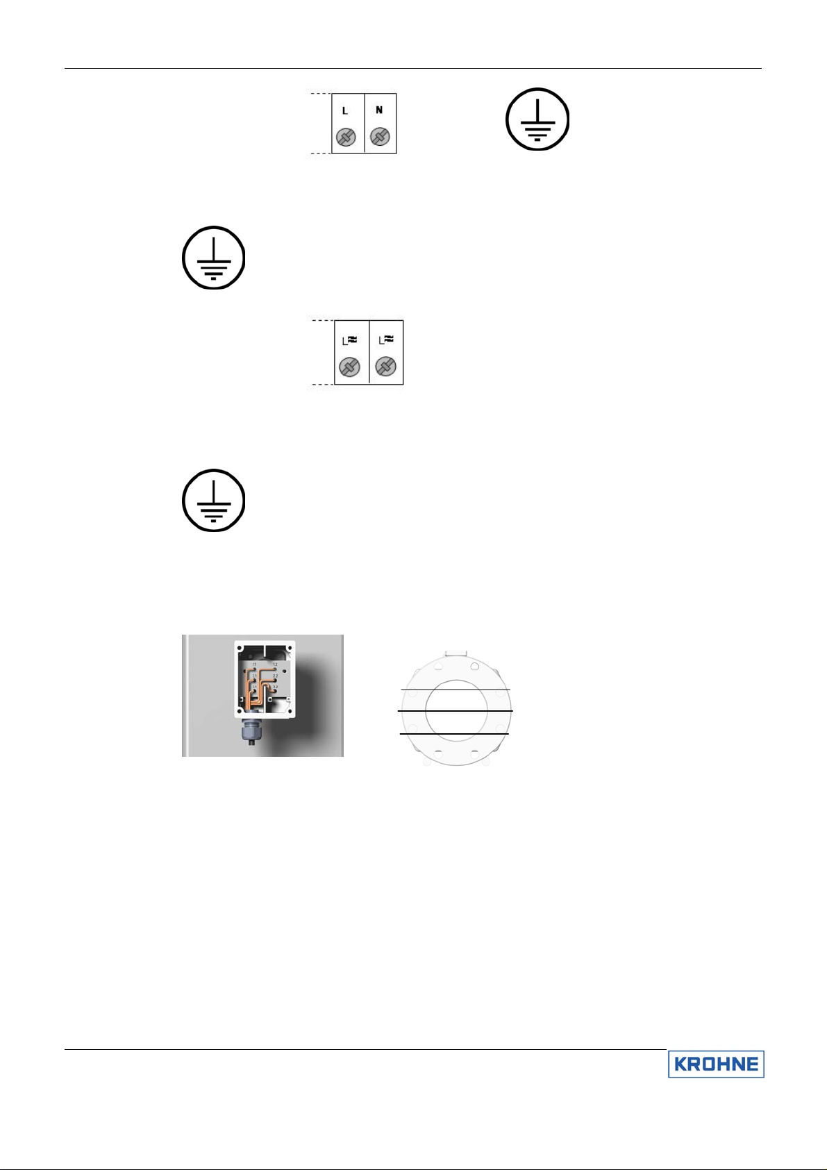
100-240 V AC supply:
The mains voltage
power supply terminal
has two connections
L Live power supply
N
Neutral power supply
Mains voltage AC supply: 100…240 V AC +10%/-15%,
48 - 63 Hz, 11 W
PE: Protective ground connection
FE: Functional ground connection
Protective conductor clamp terminal. Conductors up to 4
mm² (11 AWG) need to be connected to this terminal.
24 V AC/DC supply:
The low voltage
AC/DC power supply
terminal has two
connections
L
L
Live power supply
Neutral power supply
FE: Functional ground connection
SELV AC/DC supply:
24 V AC +10%/-15%, 48 - 63 Hz, 8 W of
24 V DC +33%/-25%, 8 W
3.5 Connection of
sensor cables
The sensors of the separate flowmeter must be connected using the factory supplied MR06 cable between the flow sensor
terminal box and the converter housing terminal box. For compact flowmeters these are connected at the factory.
Both the flow sensor terminals and the converter sensor terminals should be connected between the appropriate numbers
indicated on the sensor cable and in the terminal boxes
Cable diameter: 11 mm (0,433 inch), minimum bending radius: 8 x cable diameter.
3.2 3.1
2.2 2.1
1.2 1.1
11 ALTOSONIC III
Page 12
3.6 Electrical
connection of
the signal
inputs and
outputs
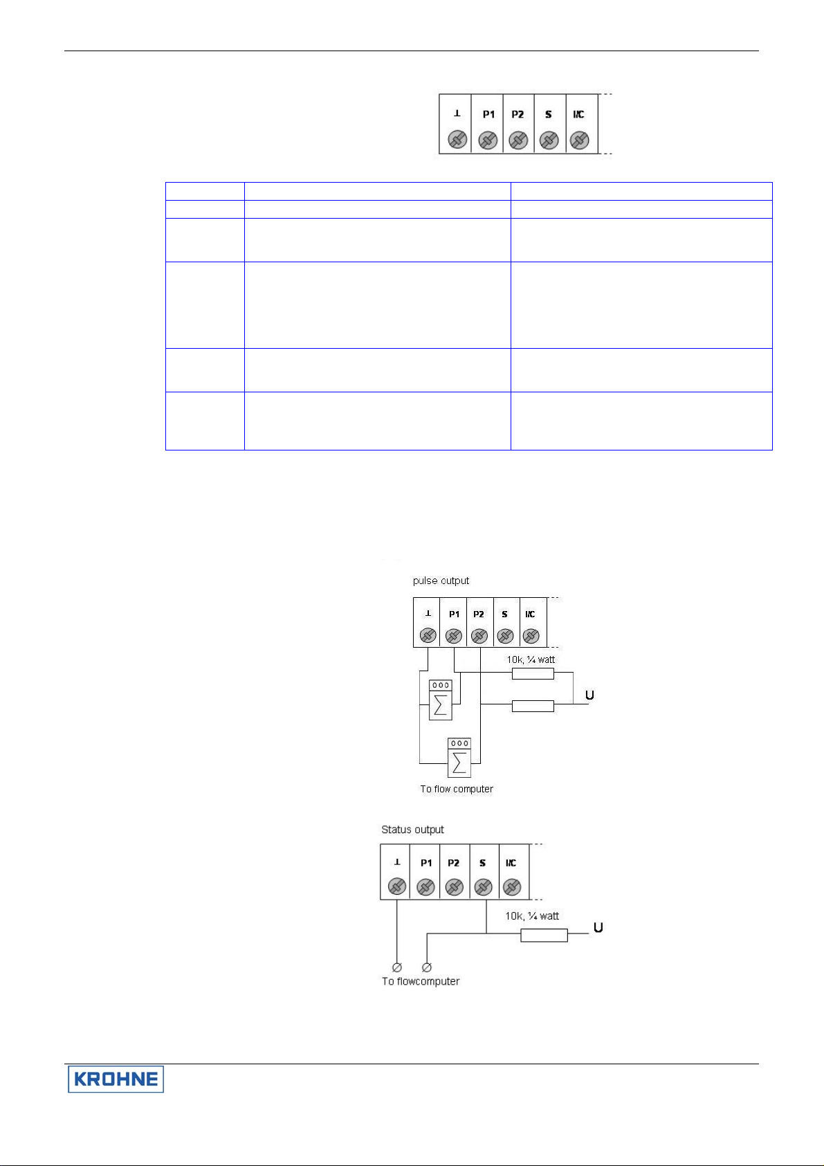
The terminal to connect the electrical signal inputs
and outputs consist of 6 connections. For wiring of
the signal inputs and outputs it is advised to use
unshielded twisted pairs.
Terminal Function Specification
⊥
P1 Pulse output 1, passive open collector output. Pulse
P2 Pulse output 2, passive open collector output. 90° or
S Status output. Function can be set via menu option
I/C Current output (I), 0(4) to 20 mA
Common ground -
output to flow computer for volume counting.
Function can be set via menu option.
180° phase shifted from P1. For pulse fidelity checking
P1 and P2 should be connected to 2 separate inputs of
a flow computer.
Function can be set via menu option.
3.5.0.
Passive open collector current sink output. Digital input
(C)
Function can be set via menu option 3.4.0. and 3.6.0.
: 150 mA
I
max
: 32V DC, 24V AC
U
max
Max frequency: 1,5 kHz
: 150 mA
I
max
U
: 32V DC, 24V AC
max
Max frequency: 1,5 kHz
I
: 150 mA
max
U
: 32V DC, 24V AC
max
Current output (I): I ≤ 22 mA,
≤ 680 Ohm. U
R
load
Digital input (C): low = 0-5 V DC, high = 15-32 V DC.
Will be switched off when current output activated.
max
The electrical input and output signals can be connected in passive mode. Please observe instrument polarity:
current (I) is always flowing towards P1, P2, S, I/C, terminals (current sink).
3.7 Connection
diagram
examples
Pulse output, P1,
P2
For supply:
U ≤ 32V DC, ≤
24V AC
= 15V DC.
Status output, S
For supply:
U ≤ 32V DC, ≤
24V AC
ALTOSONIC III 12
Page 13

Installation and operating instructions
Current output /
control input, I/C
For supply:
U = 15…24V
DC, ≥ 22mA
For supply:
15 – 30V DC, I ≥
1,5 mA
Connection to
Omni 3000/6000
flow computer
Single flow pulse
connection
Omni 6000,
Omni 3000
A/B type combo
module
Channel 3 or 4
on A type
Channel 3 only
on B type
13 ALTOSONIC III
Dual pulse
connection
for pulse fidelity
checking
Omni 6000,
Omni 3000
E type combo
module
Page 14

Flowmeter status
connection
Omni 6000,
Omni 3000
Digital I/O
module
3.8 Start-up
• Check that the flowmeter has been correctly installed. With separate systems, check before initial start-up that the correct
converter (UFC III F) is used with the correct flow sensor (UFS III F).
• Order No., see instrument type plates
• Meter size, Function 3.1.5
• Primary constant GK, Function 3.1.6
• Flow direction, Function 3.1.7
• When powered, the signal converter operates in the measuring mode. TEST, NO ERROR and IDENT NO. _ _ _ _ _ _ _ of the
signal converter appear in succession on the display. This is followed by display of the actual flow rate and/or the internal
count on a continuous or alternating basis (depending on setting, see Function 3.03 Display or Function 1.02 Display).
3.9 Operating the
signal
converter
Front panel and operating keys
The front panel and its operating keys are accessible after removing the front (glass) cover of the electronics section using the
special wrench supplied with the flowmeter.
When removing the cover, do not damage the screw thread and the gasket, never allow dirt to accumulate, and make sure that
they are well greased using Teflon grease at all times. A damaged gasket must be replaced immediately!
The converter can display several types of measured values (depending on the programming), indicated by the markers at the
display bottom line. They can be selected manually at any time by pressing the ↑ key or they are automatically cycled at 5 second
intervals.
Errors are indicated by flashing display lines and/or by the compass field. For a description of the errors and what to do, see main
“error” menu.
1. Display 1st (top) line, measured value
2. Display 2nd (middle) line, units of measured value
3. Display 3rd (bottom) line with markers ▼
to identify actual displayed value, from left to right:
Flow rate
Velocity Of Sound VOS
4. Compass field for error indication
5. Operating keys for programming the signal converter
6. Magnetic sensors to program the signal converter by means of a hand-held bar magnet
(optional) without having to open the housing. To prevent change of settings with the
cover in place sensors are only fitted for the 2 right most keys.
The function of the sensors is as follows: the right most sensor is equivalent to the right
key and the top sensor is equivalent to the center key.
ALTOSONIC III 14
Page 15

3.10 Menu
structure and
function of
operating
keys
The menu structure consists of shows the available functions for system check and configuration. Function block 0 can be
accessed with the display cover in place. For access to function block 1 to 4 the display cover has to be removed as it requires the
leftmost key for operation.
• Function block 0 Function is accessible without removing display cover. System info and error reset, can be accessed from
the measuring mode and provides detailed information on errors occurred during operation. It allows for fast and easy
resetting of the errors. System information like software version numbers can be displayed using this function. Also a display
test can be performed using this function.
• Function block 1 Operation contains a subset of options from function block 3, Installation. The options in function block 1
are selected so that the most commonly used functions can be selected quickly from this menu. In most cases only function
block 1 needs to be accessed in order to perform the required setting or programming task.
• Function block 2 Test contains all available test functions. This block can be accessed to check proper functioning off all
converter hard- and software.
• Function block 3 Installation contains all other set-up parameters for the converter. In general the converter is factory-
preset. See Service Handbook for modification instructions.
• Function block 4 Parameter Error becomes active automatically when non-plausible values have been programmed, e.g. a
too high a flow rate in too small a diameter. If this is the case menu 4 will indicate that either FULL SCALE or METER SIZE
needs to be changed.
The figure below shows the main operation structure of the converter. The cursor or flashing part of the display is shown as
underlined text.
Installation and operating instructions
15 ALTOSONIC III
Page 16

Key Measuring mode Menu mode Data level
Go to the parameter setting mode, function 1.00.00
→
OPERATION. If access CODE 1 is activated, CODE 1 must be
entered first. Using function 3.07.02 access CODE 1 can be
activated or deactivated.
Go to the error/Totalizer reset mode (via "CODE 2") Return to the previous (higher)
↵
Cycle through measured values, see Function 3.03.07 CYCL
↑
DISP
Function Text Description and settings
0.00.00 ERROR/TOT Main menu 0.00.00
0.00.01 VIEW ERR View error messages list
0.00.02 RST ERR Reset error messages
0.00.03 UP2 SW NO Software version micro processor 2
0.00.04 DSP SW NO Software version digital signal processor
0.00.05 DISPLAY Display test, all display items on
0.00.06 EXIT Leave menu 0.00
1.00.00 OPERATION Main menu 1.00.00 Operation
1.01.00 FLOW Submenu 1.01.00 Flow
1.01.01 FULL SCALE Full-scale value for 100% volume flow rate, see Function 3.01.01
1.01.02 ZERO VALUE Zero value, see Function 3.01.02
1.01.03 ZERO CAL Zero calibration, see Function 3.01.03
1.01.04 MASTER TC Master time constant, see Function 3.01.04
1.01.05 LF CUTOFF Low-flow cut-off, see Function 3.01.05
1.01.06 CUTOFF ON Cut-off active, see Function 3.01.06
1.01.07 CUTOFF OFF Cut-off de-active, see Function 3.01.07
1.02.00 DISPLAY Submenu 1.02.00 Display
1.02.01 DISP FLOW Display of flow, see Function 3.03.01
1.03.00 PULSE OUTP Submenu 1.03.00 Pulse output
1.03.01 PULSE RATE Pulse frequency value for 100% scale, see Function 3.05.08
1.03.02 PULSE/UNIT Pulse value per volume flow unit, see Function 3.05.09
2.00.00 TEST Main menu 2.00.00 Test functions
2.01.00 DISPLAY Submenu 2.01.00 Display
2.01.01 DISPLAY
2.02.00 OUTPUTS Submenu 2.02.00 Outputs
2.02.01 CURRENT Test current output
2.02.02 PULSE Test pulse/frequency output
2.03.00 INPUTS Submenu 2.03.00 Inputs
2.03.03 DIG INPUT Test digital input
2.04.00 DEV INFO Submenu 2.04.00 Device information
2.04.01 MANUFACT Display manufacturer
2.04.02 MODEL NO Display model number
2.04.03 SERIAL NO Display serial number
2.04.04 UP2 HW NO Display µP2 hardware number
2.04.05 UP2 SW NO Display µP2 software number
2.04.06 FRNT HW NO Display front end hardware number
2.04.07 DSP HW NO Display D.S.P. hardware number
2.04.08 DSP SW NO Display D.S.P. software number
2.04.09 TIME COUNT Display time counter
3.00.00 INSTALL Main menu 3.00.00 Installation
3.01.00 FLOW Submenu 3.01.00 Volume flow parameters
ALTOSONIC III 16
Test display, lights all pixels. End with ↵ key
0 mA 4 mA
12 mA 20 mA
22 mA
Use up arrow to advance. Displayed value directly present at current output. Actual value present at
output after pressing ↵ key.
1 Hz 10 Hz
100 Hz 1000 Hz
2000 Hz
Use the up arrow to advance. Displayed value directly present at Pulse output. Actual value present at
output after pressing ↵ key
Measure level at digital input. End with ↵ key.
Go to the next, lower menu level. Go to the next character or change line
(only when 2 lines are displayed)
Accept entered value
menu level or leave the menu
mode.
Cycle through menu options
within actual menu level.
Cycle active digit up to new values
Page 17

Installation and operating instructions
3.01.01 FULL SCALE Full-scale value for 100% volume and flow rate units (see Function 1.01.01). The selection of units may
be limited to SI units only.
m³/s, m³/min, m³/hr, L/s, L/min, L/hr,
US Gal/s, US Gal/min, US Gal/hr, bbls/hr, bbls/day,
********** (free user configurable unit).
3.01.02 ZERO VALUE Zero value (see Function 1.01.02)
FIXED (factory zero setting)
MEASURED (zero calibration possible, see Function 3.01.03)
3.01.03 ZERO CAL Zero calibration (see Function 1.01.03)
Carry out only at “zero” flow and with completely filled measuring tube. Duration approximately 15s with
display indicating "BUSY". STORE NO (preserve old zero value)
STORE YES (store new zero value)
3.01.04 MASTER TC Master time constant of display and current output (see Function 1.01.04)
Range: 0.02 through 99.99 s
3.01.05 LF CUTOFF Low-flow cut-off for display and outputs (see 1.01.05)
NO (fixed tripping points: ON = 0.1%, OFF = 0.2%)
YES (see Function 3.01.06 and 3.01.07)
3.01.06 CUTOFF ON Cut off “active” value
Range: 1 through 19% of Q100%
3.01.07 CUTOFF OFF Cut off “de-active” value
Range: 2 through 20% of Q100%
Value "off" must be greater than value "on"
3.01.08 METER SIZE Meter size
Selection of size from meter size table: 25-3000 mm equivalent to 1-120 inch
3.01.09 GK VALUE Flow sensor constant (GK)
Must equal flow sensor type plate value
Range: 0.02 through 20
3.01.10 FLOW DIR Definition of forward flow direction
POSITIVE
NEGATIVE
Setting in accordance with direction of arrow on flow sensor
3.01.11 MIN VOS Minimum velocity of sound (VOS)
Value used for I0% or P0% when function "VOS" selected in Function 3.04.01 or 3.05.01
Unit: m/s or feet/s
Range: 0 through 4999 m/s (0 through 15000 feet/s)
3.01.12 MAX VOS Maximum velocity of sound
Value used for I100% or P100% when function "VOS" selected in Function 3.04.01 or 3.05.01
Unit: m/s or feet/s
Range:1 through 4999 m/s (0 through 15000 feet/s)
Maximum value must be greater than minimum value
3.02.00 VERSION Submenu 3.02.00 Version
3.02.01 FUNCTION Function of converter
CUSTODY. This is factory set and can not be changed.
3.03.00 DISPLAY Submenu 3.03.00 Display (see Function 1.02.01)
3.03.01 DISP FLOW Display of flow
RATE (full-scale units)
Percent (percentage of full-scale, 0% - 100%)
NO DISPLAY (no flow display)
3.03.06 VOS Unit for Velocity Of Sound
NO DISPLAY, m/s, feet/s
3.03.07 CYCL DISP Cyclic display of measured values
NO, YES
3.03.08 ERROR MSG Display error messages
NO, YES
3.03.11 SIGN LEVEL Display signal level
NO, YES
3.04.00 CURR OUTP Submenu 3.04.00 Current output
3.04.01 FUNCTION Function of current output
OFF (switched off)
ACT FLOW (actual flow)
F/R IND (forward/reverse indication of actual flow)
VOS (velocity of sound, range is defined in Function 3.01.11 and 3.01.12)
GAIN (sensor signal gain, range is 0 dBV through 100 dBV)
3.04.02 DIRECTION Direction of current output
FORWARD (forward flow measurement)
17 ALTOSONIC III
Page 18

BOTH (forward and reverse flow measurement indicating both in the same range)
F/R SPEC (forward and reverse flow measurement indicated in different range see Function 3.04.04)
3.04.03 RANGE Range of current output
OTHER (user defined, see Function 3.04.04 through 3.04.06)
0-20/22 mA (0 pct - 100 pct / limit)
4-20/22 mA(0 pct - 100 pct / limit)
3.04.04 0 pct Current value for 0% scale
Range: 0 through 16 mA
3.04.05 100 pct Current value for 100% scale
Range: 4 through 20 mA
Value must be at least 4 mA greater than current value for 0% scale
3.04.06 LIMIT Limitation of current value
Range: 20 through 22 mA
3.05.00 PULSE OUTP Submenu 3.05.00 Pulse output
3.05.01 FUNCTION Function of pulse output
OFF (switched off)
ACT FLOW (actual flow)
VOS (velocity of sound, range defined in Function 3.01.11 and 3.01.12)
GAIN (sensor signal gain, range is 0 dBV through 100 dBV)
3.05.02 DIRECTION Direction of pulse output
FORWARD (forward flow measurement)
BOTH (forward and reverse flow measurement indicating both in the same range)
3.05.06 TIME CONST Time constant of pulse output
25 ms
MASTER TC (see Function 3.01.04)
3.05.07 OUTPUT Unit of pulse output (see Function 1.03.00)
PULSE FREQUENCY, pulses per unit time, see Function 3.05.08)
PULSE/UNIT, Totalizer pulse output, pulses per unit volume, see Function 3.05.09
3.05.08 PULSE RATE Pulse rate (frequency) value for 100 % scale
pulse/s, pulse/hr, pulse/min
Range: 1 pulse/hr through 2000 pulse/s
3.05.09 PULSE/UNIT Pulse value per volume unit for totalization
pulse/m³, pulse/l, pulse/US Gal, pulse/bbl,
free user definable unit
3.06.00 DIG INPUT Submenu 3.06.00 Digital input
3.06.01 FUNCTION Function of digital input
OFF (switched off)
RST ERROR (reset error messages)
3.07.00 USER DATA Submenu 3.07.00 User data
3.07.01 LANGUAGE Language for display texts
GB/USA (English)
D (German)
F (French)
3.07.02 ENTRY CODE Entry code for setting mode
NO (entry with key only)
YES (entry with key and code 1, factory set on 9 x key, see Function 3.07.03)
3.07.03 CODE 1 Code 1
Press any 9-keystroke combination and th en press the same combination again. Each keystroke is
acknowledged by "Ж" in the display. If both combinations are equal, "CODE OK" appears and the new
code can be stored, else "WRONG CODE" appears and the desired code has to be entered again.
3.07.04 LOCATION Tag name setting
Free settable tag for identification, maximum 10 characters.
Characters assignable to each place: A..Z / blank character / 0..9
Factory setting: KROHNE
3.07.05 UNIT TEXT Text for user-defined unit
Definition: volume/time
Characters assignable to each place: A..Z / blank character / 0..9
Fraction bar "/" in 5th place is unalterable
Factory setting: XXXX/YYY
3.07.06 UNIT VOL User-defined unit volume
Quantity of user-defined volume per m³.
Range: 10-5 through 107
Factory setting: 1
3.07.07 UNIT TIME User-defined unit time
Amount of user-defined time in seconds
Range: 10-5 through 107
Factory setting: 1
ALTOSONIC III 18
Page 19

Installation and operating instructions
3.10.01 DIG OUTPUT Function of digital status output
CUST ERR (Only errors related to custody transfer operation, also see error list)
ALL ERR (indication of all errors)
F/R IND (forward/reverse flow indication)
OVERRANGE (overrange indication)
TRIP POINT (trips when actual flow (Q) goes over a set limit, see 3.10.02 and 3.10.03 for settings)
3.10.02 TRIP PNT 1 First trip point
Range: 0 through 120% of Q100%
3.10.03 TRIP PNT 2 Second trip point
Range: 0 through 120 % of Q100%
4.00.00 PARAM ERR Main menu 4.00.00 Parameter error
4.01.00 FLOW VELOC Volume flow velocity (v) value incorrect. The flow speed is calculated from the full scale volume flow and
the meter size.
Ensure condition 0.5 m/s ≤ v ≤ 20 m/s (1,5 to 66 feet/s) is met!
4.01.01 FULL SCALE Full-scale value for 100% volume flow rate, see Function 3.01.01
4.01.02 METER SIZE Meter size, see Function 3.01.08
4.02.00 CURR OUTP Current output range incorrect. Setting for 100% is compared with setting for 0%. Ensure condition 100
pct-0 pct ≥ 4 mA is met!
4.02.01 RANGE Range of current output, see Function 3.04.03
4.02.02 0 pct Current value for 0% scale, see Function 3.04.04
4.02.03 100 pct Current value for 100% scale, see Function 3.04.05
4.03.00 LF CUTOFF Low-flow cut-off range incorrect: If low flow cut-off is set to on, the value for CUTOFF-OFF is compared
with the value of CUTOFF-ON on.
Ensure condition CUTOFF-OFF – CUTOFF-ON ≥ 1% is met!
4.03.01 LF CUTOFF Low-flow cut-off, see Function 3.01.05
4.03.02 CUTOFF ON Cut off “on” value, see Function 3.01.06
4.03.03 CUTOFF OFF Cut off “off” value, see Function 3.01.07
4.05.00 PULSE/VOS Unit of pulse output for velocity of sound function incorrect
Ensure "PULSE RATE" is selected for "VOS"!
4.05.01 PULS FUNCT Function of pulse output, see Function 3.05.01
4.05.02 PULSE OUTP Unit of pulse output, see Function 3.05.07
4.06.00 VOS Velocity of sound range incorrect:
Ensure condition MAX VOS - MIN VOS ≥ 1 m/s (3.3 ft/sec) is met
4.06.01 MIN VOS Minimum velocity of sound, see Function 3.01.11
4.06.02 MAX VOS Maximum velocity of sound, see Function 3.01.12
4.07.00 PULSE OUTP Pulse output frequency value (f) incorrect. The max frequency is calculated from the pulse/unit setting
and the max value of the measured value.
Ensure condition 1 pulse/hr ≤ f ≤ 2000 pulse/s is met.
4.07.01 PULSE/UNIT Pulse value for volume flow rate unit, see Function 3.05.09
4.08.00 PULS WIDTH Pulse output pulse width incorrect
Ensure condition pulse width ≤ 0.5 x pulse period time is met.
4.08.01 PULS WIDTH
4.09.01 CURR RANGE Range of current output, see Function 3.04.03
4.09.02 CURR 0 pct Current value for 0% scale, see Function 3.04.04
4.10.00 INP/OUTP The digital input (C) and current output (I) are not allowed to be switched on simultaneously. The current
4.10.01 INP FUNCT Function of digital input, see Function 3.06.01
4.10.02 CURR FUNCT Function of current output, see Function 3.04.01
4.10.03 CURR RANGE Range of current output, see Function 3.04.03
4.10.04 PULS FUNCT Range of pulse output, see F uncti on 3.05.01
4.13.00 EPROM EPROM checksum error, reset device.
Pulse width for frequencies ≤ 10 Hz, see Function 3.05.11
output is deactivated by setting the function of current output to off en setting the range of current output
to 0-20mA.
19 ALTOSONIC III
Page 20

3.11 Description of
functions
3.11.1 Main menu 0.00.00
Error
This menu is accessible from the measuring mode by pressing the ← key and entering "CODE 2" (↑→).
Depending on the programming of Function 3.03.08 ERROR MSG, errors occurring during process flow measurement
are represented with flashing display lines and/or a compass field. Depending on the programming of Function 3.03.07
CYCL DISP, the error messages alternate with the display of the measured value(s) every 5 seconds, or they can be
manually selected by pressing the ↑ key.
Indication of measuring path errors:
1, 2, 3: for measuring path 1,2 and 3, open or shorted sensor no measured value from
path.
4. Noise error, to much noise on measuring path(s). Flowmeter functions outside
specification.
The following list gives an alphabetical overview of error messages that can occur during process flow measurement
and what to do. The error messages only appear when Function 3.03.08 ERROR MSG is YES. Errors indicated with
“YES” in the column “via status output” the status output is activated when the error occurs
Function 0.00.01 through 0.00.06 View error messages list / Reset error messages
All occurred error messages are stored in an error messages list and can be viewed using Function 0.00.01 VIEW
ERR. The messages are kept in this list until the cause of the errors has been removed and the error messages have
been reset using Function 0.00.02 RST ERR. Errors that have been reset, but whose cause has not been removed, are
kept in the list but are displayed without bar. This allows identification of previously acknowledged and unacknowledged
errors. See table below.
1. Flashing line with number of errors that have occurred.
2. Flashing line with description of error message(s).
3. Flashing bar, indicating "new" errors, not yet
acknowledged.
4. Compass field, indicating measuring path error(s):
ALTOSONIC III 20
Page 21

3.11.2 Main menu 1.00.00
Operation
3.11.3 Main menu 2.00.00
Test functions
Error message Description of error message OIML error
CURR > MAX Current output overflow (> 22 mA) No Check flow velocity
DSP Digital signal processor (DSP) internal
error
EE MENU Menu parameters corrupted Yes Contact KROHNE representative
EE SERVICE Service parameters internal error Yes Contact KROHNE representative
EMPTY PIPE Measuring tube not completely filled,
flow reading to 0, error on all 3 paths.
FLOW > MAX Measuring range overflow (flow > 2 x
)
Q
max
FRONT END Front end internal error Yes Only checked at power-up. Switch
RESTART Flowmeter restarted No Reset errors
UNRELIABLE Flow data disturbed, same as right
compass field (4)
PATH 1 Measuring path 1 error Yes Check flow conditions
PATH 2 Measuring path 2 error Yes Check flow conditions
PATH 3 Measuring path 3 error Yes Check flow conditions
PULS > MAX Pulse output overflow (> 120 %) No Check flow velocity
UP2 µP2 internal error Yes Contact KROHNE service
VOS path 1 Deviation > 5% from average VOS of
3 measuring paths
VOS path 2 Deviation > 5% from average VOS of
3 measuring paths
VOS path 3 Deviation > 5% from average VOS of
3 measuring paths
Flow calc. Algorithm check error Yes Reset error
Cal data Yes Contact KROHNE representative
System stp System error Yes Power on/off. Contact KROHNE
Function 0.00.03 Reset Totalizer
Reset display totalizer(s). Only available when Function 3.07.08 RST ENABLE is YES. Note that all totalizer values are
reset.
The functions in this menu are a subset of Main menu 3.00.00 Installation, and are selected in this menu as most
commonly used functions for a quick installation. Note that parameters set in these functions are automatically set in
both menus.
This menu is for testing the display, the in- and outputs and for information on hard- and software numbers. See
chapter on functional checks and service.
Installation and operating instructions
What to do?
(set function
3.10.1 to CUST.
ERR)
Yes Only checked at power-up. Switch
off and on the flowmeter. If the
error still exists, contact KROHNE
representative
Yes Fill measuring tube completely
No Check flow velocity
off and on the flowmeter. If the
error still exists, contact KROHNE
representative
Yes Check flow conditions
Yes Check VOS of each path
Yes Check VOS of each path
Yes Check VOS of each path
representative when message
remains
21 ALTOSONIC III
Page 22

3.11.4 Main menu 3.00.00
Installation
Submenu 3.01.00 Volume flow parameters
Function 3.01.01 Full-scale value for 100% volume flow rate
The following units can be applied:
m³/s - cubic meter per second – US Gal/s - US gallons per second
m³/min- cubic meter per minute – US Gal/min - US gallons per minute
m³/hr- cubic meter per hour – US Gal/hr - US gallons per hour
L/s - liter per second - bbls/hr - barrels per hour
L/min -liter per minute - bbls/day - barrels per day
L/hr -liter per hour - free unit, a user-definable unit, which can be defined using Function 3.07.05 to 3.07.07.
Range depends on diameter (D) and volume flow velocity (v):
[m³/h] = 0,9 x D² (v
Q
min
[m³/h] = 31,25 x D² (v
Q
max
[US GPM]= 3,9 x D² (v
Q
min
[US GPM] = 138 x D² (v
Q
max
= 0.5 m/s)
min
max
min
max
Function 3.01.02 through 3.01.03 Zero value / Zero calibration
Although zero calibrated at the factory the flow sensor might still give an offset flow reading, at "zero" flow in the
pipeline (measuring tube completely filled with medium. Function 3.01.02 ZERO VALUE can be used for zero
calibration. It can be set to either FIXED, which will give a factory zero setting, or MEASURED, which will allow to
compensate for the small signal using Function 3.01.03 ZERO CAL.
Function 3.01.04 Master time constant of display and outputs
This is the time that it takes for the display and the current and pulse outputs to reach 66% of the end value, after a
change in the flow rate. The time constant does not apply for totalization. The time constant does not apply for the
current output in F/R setting. If required, a different time constant value can be set for the pulse/frequency output under
Function 3.05.06 TIME CONST.
Function 3.01.05 through 3.01.07 Low-flow cut off for display and outputs / Cut off "on" value/ Cut off "off"
value
Due to the extreme low flow sensitivity of the ALTOSONIC III, it will detect the slightest movement of fluid, even at zero
flow. To avoid these measurements causing outputs and totalizer changes, the low flow cut-off can be used to force
reading to zero. These are set as a percentage of Full Scale, as configured in Fct.1.01.01 or 3.01.01.
When the flow rate decreases below the "on" value, the display and outputs are set to their "zero" values. When the
flow increases above he "off" value, measurements are resumed. The "off" value must be larger than the "on" value by
at least 1%. With Function 3.01.05 LF CUTOFF set to NO, factory settings are used for the "on" and "off" values.
Function 3.01.08 Meter size
The nominal diameter of the measuring tube. See the flow sensor nameplate. This value can be entered In mm or in
inches.
Function 3.01.09 Flow sensor constant GK
At the factory, each flow sensor is calibrated and supplied with a calibration constant. This constant can be found on the
flow sensor nameplate.
Function 3.01.10 Definition of forward flow direction
The forward flow direction is indicated with an arrow on the flow sensor. If the actual flow is in the direction of the arrow
then the flow is in the positive direction and the converter will have a positive flow reading. By setting this function to
NEGATIVE, the converter's reading can be reversed. This can be useful when the process flow direction is changed so
the flow sensor will not need to be reversed.
Function 3.01.11 through 3.01.12 Minimum/Maximum velocity of sound
In media of varying composition, the ultrasonic wave speed will vary, like in oil-water mixtures. This is identifiable by
means of measuring the velocity of sound. The current output and the pulse output can be programmed to indicate the
velocity of sound, see Function 3.04.01 and 3.05.01. Their "zero" values (0% scale) will then correspond with the
velocity of sound set in Function 3.01.11 MIN VOS, where their "full-scale" values (100% scale) will correspond with the
velocity of sound set in Function 3.01.12 MAX VOS. See also Function 3.03.06 VOS for the display of the velocity of
sound. NOTE: Only necessary for setting span for outputting VOS, is not needed to measure flow!
Submenu 3.02.00 Version
Function 3.02.01 Function of converter
The function of the converter is factory preset to CUSTODY and can not be altered.
= 20 m/s)
= 1.5 feet/s)
= 20 m/s)
ALTOSONIC III 22
Page 23

Submenu 3.03.00 Display
Function 3.03.01 Display of flow
To display the flow, three options are available
Rate; flow is shown with the unit as set in function 3.01.01
Percentage; flow is shown as a percentage of the full scale as set in 3.01.01
No display; no flow is shown.
Function 3.03.06 Unit for velocity of sound
The display of the velocity of sound, as described in Function 3.01.11 through 3.02.12.
The following units can be applied:
NO DISPLAY no display of velocity of sound
m/s meter per second
feet/s feet per second
Function 3.03.07 Cyclic display of measured values
Whenever more than one measured value is to be displayed (e.g. flow rate and totalizer), each value can be selected
manually by pressing the ↑ key, or the values can be alternately displayed each 5 seconds by turning the cyclic display
function on. This also includes the display of various readings as described in Function 3.03.08 through 3.03.11.
Function 3.03.08 Display error messages
Enable/disable the display of error messages as described in section 5.1. When enabled, the converter display will
FLASH when an error occurs, and the error code will be displayed. It will continue to flash until the alarm is
acknowledged or cleared. An unacknowledged alarm will be displayed with 3 horizontal lines in front of the error
message. Acknowledging the alarm will remove the lines. If the alarm is acknowledged but the cause is not removed
the error will stay in the error list. To remove the error from the list the cause must be removed and the error must be
reset. When it is turned off, the compass display indicates errors are present, but the display will not flash.
Function 3.03.11 Display gain
Enable/disable the display of the signal level from the sensors. For each measuring path this level is displayed as a
gain value 0 dBV through 80 dBV at the input amplifier.
Submenu 3.04.00 Current output
Function 3.04.01 Function of current output
The current output can be programmed for the following functions:
• OFF switched off, current output steady at current value for 0 % scale, see Function 3.04.03 ACT FLOW
proportional with the actual volume flow, see Function 3.01.0.1 FULL SCALE.
• F/R IND forward/reverse flow indication, see Function 3.01.10, 100 pct mA value for forward flow, 0 pct mA value
for reverse flow, see Function 3.04.03 through 3.04.05.
• VOS proportional with the velocity of sound, see Function 3.01.11 through 3.01.12.
• SIGN LEVEL proportional with the signal level, see Function 3.03.11.
Function 3.04.02 Direction of current output
Only available when ACT FLOW is selected in Function 3.04.01. When FORWARD is selected, the current output will
only be active when the flow is in the forward flow direction as defined in Function 3.01.10 FLOW DIR, while when
BOTH is selected, the current output will be active forward and reverse flow direction. Use F/R SPEC to indicate the
reverse flow in the range from 0 mA through 0 pct mA (see Function 3.04.04 0 pct). I.e. when the flow goes from the
forward direction to the negative direction, the current output will pass the "0 pct" mA value down to 0 mA, where it
stops.
Installation and operating instructions
23 ALTOSONIC III
Page 24

Abbreviations used:
I Current output
QF Forward volume flow rate
Current output at 0 % scale
I
0%
Current output at 100 % scale
I
100%
QR Reverse volume flow rate
Current output maximum
I
max
When VOS or signal gain is set, only the forward characteristic applies.
Function 3.04.03 Range of current output
The range of the current output can be set to standard 0-20mA or 4-20 mA or to “other” for other user specified spans.
Max reading is 22 mA. The range for “other” is set using functions 3.04.04 to 3.04.06.
Function 3.04.04 0 pct
mA setting for 0 percent of the range. It can be set between 0 and 16 mA. Default is 4 mA.
Function 3.04.05 100 pct
mA setting for 100 percent of the range. It can be set between 4 and 20 mA. Default is 20 mA.
Function 3.04.06 Limit
Limit of current output. Max setting and default setting: 22 mA. Limit it to 20mA when safety systems reserve highe r
currents as Fault Codes.
Submenu 3.05.00 Pulse / frequency output
Function 3.05.01 Function of pulse output
The pulse output can be programmed for the following functions:
• OFF switched off, contact closed.
• ACT FLOW proportional with the actual volume flow, see Function 3.01.01 FULL SCALE.
• CORR FLOW proportional with the corrected volume flow, availability depending on version, see Function 3.02.01.
• F/R IND forward/reverse flow indication, see Function 3.01.10, contact closed for forward flow, contact open for
reverse flow.
• VOS proportional with the velocity of sound, see Function 3.01.11 through 3.01.12.
• DIG OUTPUT digital output, see Function3.05.03.
• SIGN GAIN, gain of sensor amplifier, proportional with the signal level, see Function 3.03.11.
Function 3.05.02 Direction of pulse output
Only available when ACT FLOW is selected in Function 3.05.01. When FORWARD is selected, the pulse output will
only be active when the flow is in the forward flow direction as defined in Function 3.01.10 FLOW DIR, while when
BOTH is selected, the pulse output will be active in both flow directions.
Function 3.05.06 Time constant of pulse output
The time constant of the pulse output can be set to 25 ms, which is the lowest value, or MASTER TC, which will result
in the value, set in Function 3.01.04 MASTER TC. The time constant setting only applies to actual flow and corrected
flow.
Function 3.05.07 pulse output function
The function of the pulse output can be set to either PULSE RATE (frequency) or PULSE/UNIT (Totalizer pulse).
PULSE RATE: Is set by entering a frequency at 100 % volume flow rate.
PULSE/UNIT: Is set by entering a value for the number of pulses for each volume (or energy) unit. Each pulse having a
fixed volume, i.e. 1 pulse / 0.1 liter. This is the best method of remote totalizing, as pulses simply need to be counted,
i.e. 10 pulses = 1 liter. See Function 3.05.08 through 3.05.10.
Function 3.05.08 Pulse rate
If the function of 3.05.07 is set to pulse rate, the frequency of the pulse can be set that will be available at 100% flow.
The frequency can be set to: pulse/s, pulse/min, pulse/hr. The default setting is 1000 pulses/second (Hz), the max
setting is 1500.
Function 3.05.09 Pulse/unit
If the function of 3.05.07 is set to pulse/unit, the unit and number of pulses per unit can be set for the flow measurement
using this function. Options are; pulse/m³, pulse/l, pulse/US Gal., pulse/bbl. Also a user definable unit can be set. The
max number of pulses per unit is 7870000, the default setting is 1. NOTE: Check that the max. flow span will not cause
the number of pulses generated per second to exceed the maximum of 2 000 Hz.
ALTOSONIC III 24
Page 25

Submenu 3.06.00 Digital input
Function 3.06.01 Function of digital input
The digital input terminal is the same as the current output terminal. Therefore, when the digital input function is
selected, the function of the current output (see Function 3.04.01) needs to be set to OFF and the current output range
has to be set to 0-20mA (see Function 3.04.03).
The digital input can programmed for the following functions:
• OFF switched off, no function
• RST ERROR reset error messages, see also Function 0.00.02 RST ERR
Submenu 3.07.00 User data
Function 3.07.01 Through 3.07.04 Language for display texts / Entry code for setting mode / Code 1 / Tag name
setting
Function 3.07.05 through 3.07.07 User-defined unit for volume flow rate
Instead of choosing from pre-defined units for the volume flow as in Function 3.01.01 FULL SCALE, a user-defined unit
can be programmed. This unit is to be defined as a volume unit per time unit. In Function 3.07.05 UNIT TEXT the text
can be defined, in Function 3.07.06 UNIT VOL the amount of volume units that will fit in one m³ must be programmed,
and in Function 3.07.07 UNIT TIME the amount of seconds that will fit in a time unit must be programmed.
Example: to program barrels per day, program in Function 3.07.06 6,289 (= 1/0,159) and in 3.07.07 8,640E4
(=24*60*60).
3.11.5 Main menu 4.00.00
Parameter error
For description see under main menu 0.00.00.
Installation and operating instructions
25 ALTOSONIC III
Page 26

4. Functional
checks and
service
4.1 Functional checks
4.1.1 Display test Function 2.01.01 Display test
4.1.2 Current output test Function 2.02.01 Test, current output I
4.1.3 Frequency output
test
4.1.4 Status output test 2.03.03 Test of the status inputs (if applicable)
4.2 Device information 2.04.00 Device info
4.3 Measuring zero flow
value
The signal converter has several different test functions (Function 2.01.01 to 2.01.05).
Select function 2.01.01 as described above.
Press right arrow to start.
All segments in the 3 lines of the display are activated sequentially. The test can be terminated by pressing ← key.
WARNING – This will affect the current output, and will no longer be process output!
A milliamp-meter must be connected between terminals V+ and I for this test, see the connection diagrams.
Select current value with ↑ key:
0 mA - 4 mA
12 mA - 20 mA
22 mA
The milliamp-meter indicates the current value selected. Press the ← key to terminate the test and display the actual
value again
Function 2.02.02 Test, frequency output F
WARNING – this will affect the pulse/frequency output, and will no longer be process output!
An electronic totalizer (EC) must be connected to terminal P. for this test.
Select function 2.02.02. Select frequency value with ← key:
1 Hz - 10 Hz
100 Hz - 1000 Hz
1500 Hz
The totalizer indicates the frequency value selected. Press the ← key to terminate the test and display the actual value
again.
Connect a voltage source to terminal I/GND.
Select Function 2.03.03.
Apply a voltage < 5 V and check if the display indicates a '0' level as value.
Apply a voltage >15 V and check if the display indicates a '1' level as value.
Press '<-' to terminate.
Select the 2.04 menu. The various sub-menus (2.04.01 to 2.04.09) will show:
• manufacturer
• model no.
• serial no.
• uP2 hardware no.
• uP2 Software no.
• Front Hardware no.
• DSP Hardware no.
• DSP software no.
• Time count
Set zero flow in the pipeline. Make sure the flow sensor is completely filled with liquid.
Select function 1.01.02 or 3.01.02, ZERO VALUE and set this to MEASUREMENT
Select 1.01.03 or 3.01.03, ZERO CAL, zero calibration will start upon entry of this function.
the zero measurement will take approximately 15 seconds, display indicating BUSY. At the end the display shows
"STORE NO". Use the '^' to select "STORE YES" if desired use the "<-" to store and exit the zero calibration routine.
Remark: if fixed zero value is selected (1.01.02 or 3.01.02) a zero calibration routine is not possible.
ALTOSONIC III 26
Page 27

Installation and operating instructions
5. Installation in
hazardous
areas, zone 1
and zone 2
5.1 Approvals
5.2 Compact flowmeter
5.3 Flow sensor
27 ALTOSONIC III
The ALTOSONIC III ultrasonic flowmeters in compact and separate design are in accordance with the European
Directive 94/9 EC (ATEX 100a) and approved for hazardous classified locations of Zone 1 and 2 by the PTB conform to
the European Standards of the EN 500xx series, approval number: PTB 03 ATEX 2021 X.
The standard ALTOSONIC III C-EEx compact flowmeter is designed for ambient temperatures (i.e. Ta) in the range of
-40°C / 104°F up to +70°C/158°F. The maximum allowed process liquid (medium) temperature is restricted by the
combustible atmosphere that (possibly) surrounds the apparatus, determined by the temperature class of the
atmosphere, see table below.
Temperature class Maximum process liquid temperature at
Ta ≤ 40°C / 104°F Ta ≤ 50°C / 122°F Ta ≤ 60°C / 140°F
T6
T5
T4
T3
The ALTOSONIC III K/…-EEx compact flowmeter consists of the UFC III…-EEx flow converter that is screwed on top of
the UFS III-EEx flow sensor by four hexagonal socket head cap screws of size M6. The standard compact flowmeter is
marked with one of the codes below:
Standard: II 2G EEx de [ib] IIC T6…T3 for the terminal compartment of the flow converter housing in type of protection
increased safety "e" according to EN 50019.
Optional: II 2G EEx d [ib] IIC T6…T3 for the terminal compartment of the flow converter housing designed as
flameproof enclosure "d" according to EN 50018.
The UFS III…-EEx flow sensor is the measuring unit of the ALTOSONIC III (3-beam) ultrasonic flowmeters. It contains
the ultrasonic sensor (three pairs of opposite transducers) in type of protection intrinsic safety category "ib" according to
EN 50020. All sensor circuits are wired by separate coaxial cables and connected through SMB connectors, which are
marked by the respective numbers 1.1, 1.2, 2.1, 2.2, 3.1 and 3.2. The flow sensors are available in size DN25 (1”) up to
DN1000 (40”) in diameter.
The UFS III…-EEx flow sensor is used in combination with the flow converter unit type UFC III…-EEx, which is either
directly mounted on top of the flow sensor (compact meter) or installed on a distance and connected via a cable
(separate version). In the last case the flow sensor as well as the flow converter unit are both provided with a junction
box, in which the SMB connectors are mounted.
The UFS III F/…-EEx flow sensor in separate design is the measuring unit of the separate flowmeter system. The
sensor is suitable for process liquid temperatures from -25°C/-13°F up to +180°C/356°F and designed for an ambient
temperature in the range of -40°C/-40°F up to +70°C/158°F.
The UFS III F/…-EEx flow sensors in separate design are classified according to the temperature classification table
below.
Temperature class Maximum process liquid temperature at Ta = 60°C / 140°F
T6
T5
T4
T3
The UFS III F/…-EEx flow sensors are marked with the explosion safety codes: UFS III F-EEx: II 2G EEx ib IIC T6…T3.
The intrinsically safe "ib" ultrasonic sensor circuits inside the UFS III…-EEx flow sensor have the following maximum
values (i.e. entity parameters):
Maximum input voltage : V
80°C / 176°F 80°C / 176°F 80°C / 176°F
95°C / 203°F 95°C / 203°F 95°C / 203°F
130°C / 266°F 130°C / 266°F 125°C / 257°F
180°C / 356°F 165°C / 329°F 125°C / 257°F
80°C / 176°F
95°C / 203°F
130°C / 266°F
180°C / 356°F
= 13.1 V
max
Page 28

Maximum input current : Imax = 600 mA
Maximum internal capacitance : Ci = 13.1 nF (maximum, 3 sensor circuits)
Maximum internal inductance : Li = 134 µH (maximum, 3 sensor circuits)
The intrinsically safe sensor circuits of the ALTOSONIC III C/…-EEx compact flowmeter are only internal circuits and
not accessible for the user.
5.4 Flow converter
The UFC III…-EEx flow converter consists of an approved cylindrical housing, made of a stainless steel (type VX-EEx
with PTB No. Ex-96.D.1068 U). It contains two separate compartments, divided from each other by wall with an
integrated encapsulated flameproof terminal feed-through. The housing of the compact version is screwed on top of the
flow sensor, the housing of the separate version is screwed on an aluminium or stainless steel wall-mounting bracket. A
junction box made of stainless steel is screwed to the side of the bracket by four M6 recessed head screws with internal
hexagonal socket set (only applicable for the flow converter in separate design).
The flow converter housing is on both ends closed by a threaded cylindrical cover with O-ring sealing. Coaxial cables of
type RG179 or RG316 with SMB plugs at their ends connect the intrinsically safe sensor output circuits of the flow
converter to the corresponding SMB male-to-male bulkheads in the junction box.
The equipotential bonding conductor is screwed under the external M5 U-clamp terminal, which is located on the
mounting flange at the bottom of the neck of the flow converter housing. The flow converter housing has an ingress
protection degree of at least IP67 in accordance with EN 60529.
Electronics compartment
The electronics compartment accommodates the UFC III…-EEx electronics unit. The compartment is designed with type
of protection flameproof enclosure "d" in accordance with EN 50018. It is closed by a flameproof display cover with
glass window, which is glued and additionally mechanical supported by a screwed in back-up ring made of aluminum or
stainless steel (depends on the material of the housing). The interconnecting part (i.e. neck) at the bottom of the
housing contains a flameproof cable feed-through, through which the coaxial cables run. The feed-through provides a
flameproof sealing at the bottom of the electronics compartment.
The UFC III…-EEx electronics unit is inserted into the electronics compartment with the help of two sliding rubbers that
position and fixate the unit at the front of the inside of the housing. Two M4 screws mount the unit and a third M4 screw
fixates the brass earth strip at the back-end of the front-end printed circuit board, which contains the integrated
voltage/current limiting circuit. The three screws are screwed to the integrated wall inside the electronics compartment.
The on the front-end PCB integrated voltage/current limiting circuit provides the ultrasonic sensors inside the flow
sensor with type of protection intrinsic safety category "ib" according to EN 50020.
The voltage/current limiting circuit has the following maximum output values:
Maximum output voltage : V
Maximum output current : I
Maximum allowed external capacitance : C
Maximum allowed external inductance : L
= 8.15 V
O
= 220 mA
O
ALTOSONIC III 28
Terminal compartment
The terminal compartment accommodates seven M4 clamp terminals for connection of the power supply and the signal
in-/output circuits. The terminals are separated from each other by insulation plates (eight in total, from which one at
each end of the row).
The terminal compartment (default in type of protection increased safety “e”) is standard equipped with two metal cable
glands of size M20x1.5 or Pg13.5. The terminal compartment can optionally be provided as a flameproof enclosure
“EEx d”, in which case the customer must use pre-certified
“EEx d” cable glands or conduits.
For flameproof conduit systems, the terminal compartment must have type of protection flameproof enclosure “d”
according to EN 50018. The conduits must be sealed by “EEx d” approved (in accordance with ATEX 100a directive)
sealing devices (i.e. stopping boxes) directly at the conduit entrances of the as flameproof enclosure “EEx d” performed
terminal compartment.
“EEx d” approved cable glands are no part of the standard delivery package, but must be provided by the customer
himself or ordered explicitly at KROHNE.
1) Semi-circular insulating cover plate
2) U-clamp terminal size M4 (7 in total)
3) Dividing plate of insulating material (8 in total)
4) Flameproof terminal fe ed-through
= 1.3 µF
O
= 0.5 mH
O
Page 29

Installation and operating instructions
5) Sticker with handling instructions for insulating cover plate
6) Metal dividing plate intrinsically safe and non-intrinsically safe terminals
7) Cable gland (size M20x1.5 or Pg13.5) or cable adapter (e.g. M20x1.5 to ½ inch NPT)
8) PE/FE U-clamp terminal size M5
9) External U-clamp terminal size M5 for equipotential bonding cable.
5.5 Technical data
Electrical power supply unit
The UFC III…-EEx electronics unit is equipped with a switching-mode power supply, which is available in two supply
voltage ranges, namely:
• 100…240 V AC power supply;
• 24 V AC/DC power supply.
The power supply’s mains transformer provides the galvanic separation between the primary circuit (i.e. mains supply)
and the secondary circuits. The secondary windings of the mains transformer deliver the following output voltages:
The table below lists the electrical input voltages of the power supply units, at the primary side of mains transformer.
Power supply Nominal voltage Tolerances Mains supply
voltage
24 V AC/DC 24 V AC -15/+10% 20.4 V AC 24 V AC/DC 24 V AC
24 V DC -25/+33% 18 V DC 32 V 24 V DC
100…240 V AC 100…240 V AC -15/+10% 85 V AC 100…240 V AC 100…240 V AC
The table below lists the electrical data of the power supply outputs.
Minimum Maximum Limit
Power supply Nominal
voltage
(1) Depends on the load.
Power supply output Parameter Minimum Nominal Maximum Limit
Electronics pos. supply
Electronics neg. supply
Analogue input driver
Voltage +5.4 V +6 V +6.54 V (1) 40 V
Current 225 mA 400 mA 571 mA Voltage -5.2 V -6 V -9 V 40 V
Current 20 mA 50 mA 88 mA Voltage 21.6 V 24 V 26.4 V 40 V
Intrinsically safe sensor circuits
The on the front-end printed circuit board integrated voltage/current limiting circuits are connected via SMB receptacles
of type Radiall R114 665 (for coaxial cables). They are soldered into the PCB at the front side of the board (close to the
local display unit). The connections are established during the installation of the UFC III…-EEx electronics unit inside
the flameproof electronics compartment of the flow converter housing by KROHNE personnel.
Signal in-/outputs
Standard versions: Connector X1, pins 1, 2, 3, 4 and 5 on power supply PCB
24 V DC ±10% (40 V DC max) , 0-22 mA (100 mA max), Vm = 264 V
Ultrasonic sensor circuits: 6 separate SMB connectors X1, X2, X6, X7, X10 and X11 on front-end PCB in type of
protection Intrinsic Safety EEx ib IIC. Maximum values (i.e. entity parameters):
Vo = 8.15 V, Io = 220 mA
Lo = 0.5 mH, Co = 1.3 µF
Environment temperatures: Ambient temperature Ta -40°C...+70°C / Ta -40°F...+158°F
Component ambient temperature Tac (inside closed converter housing): during unfavorable operation 85°C / 185°F
under fault conditions 100°C / 212°F.
Power dissipation
At nominal supply voltage and full load at the outputs, the nominal power dissipation of the UFC III…-EEx with the
100…240 V AC power supply is limited at a maximum of 11 W and with 24 V AC/DC supply, limited to 8 W.
29 ALTOSONIC III
Page 30

6. Electrical
installation
6.1 General
6.2 Connecting cables Cable A
6.3 Connection diagrams
The field cables enter the terminal compartment of the UFC III…-EEx flow converter unit (i.e. power supply, current and
signal in-/outputs) and are non-intrinsically safe.
To connect external devices to the in-/output terminals, the wiring requirements for the type of protection of the
compartment (standard: increased safety "e", optional: flameproof "d") must be conform to the international or national
standard involved (e.g. DIN VDE 0165, paragraph 5.6).
To connect external devices to the in-/output terminals, the wiring requirements for the specific type of protection of the
terminal compartment (standard: increased safety "e", optional: flameproof enclosure "d") must be respected, see
standard EN 60079-14 or the corresponding national standard.
The non-intrinsically safe terminals for connection of the power supply (L, 1L≈ and N, 0L≈) must be connected in
accordance with the relevant standard code of practice for electrical apparatus intended for use in potentially hazardous
locations, type of protection increased safety "e" or type of protection flameproof enclosure "d", depending on the type
of protection of the terminal compartment of the flow converter housing.
Signal cable for current output and binary in-/outputs (pulse and status output). This cable
Cable B
Cable C
Equipotential bonding
conductor
The following diagrams show the connection diagrams of respectively the compact ultrasonic flowmeter system and
remote ultrasonic flowmeter system (def ault).
type must be in accordance with clause 9 of the EN 60079-14 "Electrical installations in
hazardous locations" or an equivalent national standard (e.g. DIN VDE 0165 Part 1).
Mains power supply cable. This cable type must also be in accordance with clause 9 of the
EN 60079-14 "Electrical installations in hazardous locations" or an equivalent national
standard (e.g. DIN VDE 0165).
Rated voltage: 500 V
Examples: H07..-., H05..-. to HD 21.S2 or HD22.S2
MR06 coaxial cable (only for remote default version), to be supplied by KROHNE.
Technical data:
Test voltage: 500 V
Diameter of strand (core and screen): 0.1 mm
Distributed capacitance (core/screen): 67 pF/m
Distributed inductance (core/screen): 0.4 µH/m
Minimum cross-sectional area;
unprotected: 4 mm
protected by metal conduit: 2.5 mm
2
(11 AWG)
2
(14 AWG).
ALTOSONIC III 30
Page 31

Installation and operating instructions
31 ALTOSONIC III
Page 32

ALTOSONIC III 32
Page 33

A
7. Service and
maintenance
7.1 Introduction
7.2 Replacement of
electronics unit or
power fuse(s)
Contact your nearest local KROHNE representative for ordering information of the UFC III…-EEx electronics units and/or
fuses.
The ALTOSONIC III ultrasonic flowmeters are maintenance free with regard to the flow metering properties. Within the
scope of the periodical inspections, which are required for electrical apparatus that is installed and used in a hazardous
classified location, it is recommended to check the flameproof converter housing on signs of corrosion and damages
The following instructions must always be carefully followed, if the flow converter housing in which the UFC III…-EEx is
installed has to be opened respectively closed again!
Before opening:
• Make absolutely sure that there is no explosion hazard!
• Gas-free certificate!
• Make sure that all connecting cables are safely isolated from all external sources!
• Allow the prescribed waiting time to elapse before opening the housing: 20 minutes for temperature class T6 and 11
minutes for temperature class T5!
When the instructions above are strictly followed, the cover (including a glass window) of the electronics compartment may
be removed. First unscrew the recessed head screw of the interlocking device by a hollow-head screw wrench size 3, until
the cover can rotate freely. Unscrew the cover with the special plastic wrench (black) that is supplied with the apparatus.
After opening:
• The copper grounding strip at the back of the electronics unit must be securely screwed to the housing (back-end of
electronics compartment) by screw C (see figure below). The electronics unit is screwed into the electronics
compartment by two screws B. Before screws B and C can be accessed, the display unit must be removed via screws
A.
• Before the cover is screwed back into the housing, the screw-thread must be clean and well-greased with an acid and
resin-free grease, e.g. teflon grease.
• Screw the cover as tight as possible into the housing by hand, until it cannot be opened by hand anymore. Screw the
recessed head screw of the interlocking device tight.
Installation and operating instructions
A
B
C
B
Display unit Electronics unit after removal of display unit
33 ALTOSONIC III
Page 34

7.3 Replacement of
electronics unit
7.4 Replacement of
mains fuse
Refer to the instructions for information about resetting and reprogramming the new electronics unit after replacement.
Important application specific should be noted before replacing the UFC III…-EEx electronics unit!
Before commencing work, note the “Before opening” instructions, then continue as follows:
• Remove the cover of the electronics compartment.
• Unscrew the two screws A of the display unit and turn display unit carefully aside or remove the unit completely by
taking out the flat cable connector.
• Unscrew the two mounting screws B of the electronics unit as well as screw C, which fixes the copper earth strip at the
back of the housing. A screwdriver with a long shaft (200 mm) can best be used to unscrew C (e.g. screwdriver type
Philips No. 2).
• Carefully pull the electronics unit slightly out of the converter housing, until the SMB connectors of the coaxial cables
can easily be unplugged. Then remove the complete electronics unit from the housing.
• Carefully insert the new electronics unit until the numbered SMB connectors can be connected to the corresponding
numbered SMB receptacles on the electronics unit. Then mount the unit completely into the housing and fix the
screws. First C, then B and finally screw the display unit on the electronics via screws A, after the flat cable connector
is connected.
• Screw the cover of the electronics compartment back into the housing.
Note the “After opening" instructions during reassembling.
Carefully keep the coaxial cables to the side of the housing, while inserting the electronics unit into respectively removing it
from the converter housing. This is to prevent damaging of the coaxial cables!
Before commencing work, note the “Before opening” instructions, then continue as follows:
• Remove the cover of the electronics compartment.
• Unscrew the two screws A of the display unit and turn the display unit carefully aside.
• The fuse-holder, in which the mains fuse in accordance with IEC 127-2 size Ø5 x 20 mm is mounted, is now
accessible to replace the defect power fuse by a new fuse with the same rating. The 100…240 V AC power supply
(see figure below) is provided with a fuse rated at T 0.8 A / 250 V, the 24 V AC/DC power supply has a fuse of T 1.25
A / 250 V (see figure below).
• Reassemble the unit in reverse order.
Note the “After opening" instructions during reassembling.
ALTOSONIC III 34
Power supply PCB - 100…240 V AC Power supply PCB - 24 V AC/DC
Page 35

7.5 Returning the
flowmeter to
KROHNE for service
or repair
.
Installation and operating instructions
KROHNE will only service your flowmeter if it is accompanied by a statement in line with the following model confirming
that the flowmeter is safe to handle.
If the flowmeter has been operated with toxic, caustic, flammable or water polluting liquids, you are kindly requested:
To check and ensure, if necessary by rinsing or neutralizing, that all cavities in the flowmeter are free from dangerous
substances.
To enclose a statement with the flowmeter confirming that the flowmeter is safe to handle and stating the liquid used.
KROHNE regrets that they can not service your flowmeter unless accompanied with such a statement.
The following specimen statement is available on the KROHNE website as a word file.
Simply download and use the tabulator key to go from one fill-out field to the next. Please attach the form to the returned
meter.
Specimen statement:
Company:
Department:
Address:
Name:
Tel. No.
Details enclosed flowmeter:
Type:
KROHNE Order No.
Has been operated with the following liquid:
Because the liquid is:
water-pollutant toxic caustic flammable (tick where applicable)
We have checked that the flowmeter and all cavities in the flowmeter are
free from such substances flushed* out and neutralized.
* delete where not applicable
We hereby confirm that there is no risk to man or environment through any residual liquid in or on the flowmeter or in any
of its cavities.
Date: Place:
Signature: Company Stamp:
35 ALTOSONIC III
Page 36

Appendix 1 EC Type examination certificate
ALTOSONIC III 36
Page 37

Installation and operating instructions
37 ALTOSONIC III
Page 38

ALTOSONIC III 38
Page 39

Installation and operating instructions
39 ALTOSONIC III
Page 40

ALTOSONIC III 40
Page 41

Appendix 2 Declaration of conformity
Installation and operating instructions
41 ALTOSONIC III
Page 42

Appendix 3 Type plates
ALTOSONIC III 42
Page 43

Notes
Installation and operating instructions
43 ALTOSONIC III
 Loading...