

Page 1
Installation instructions
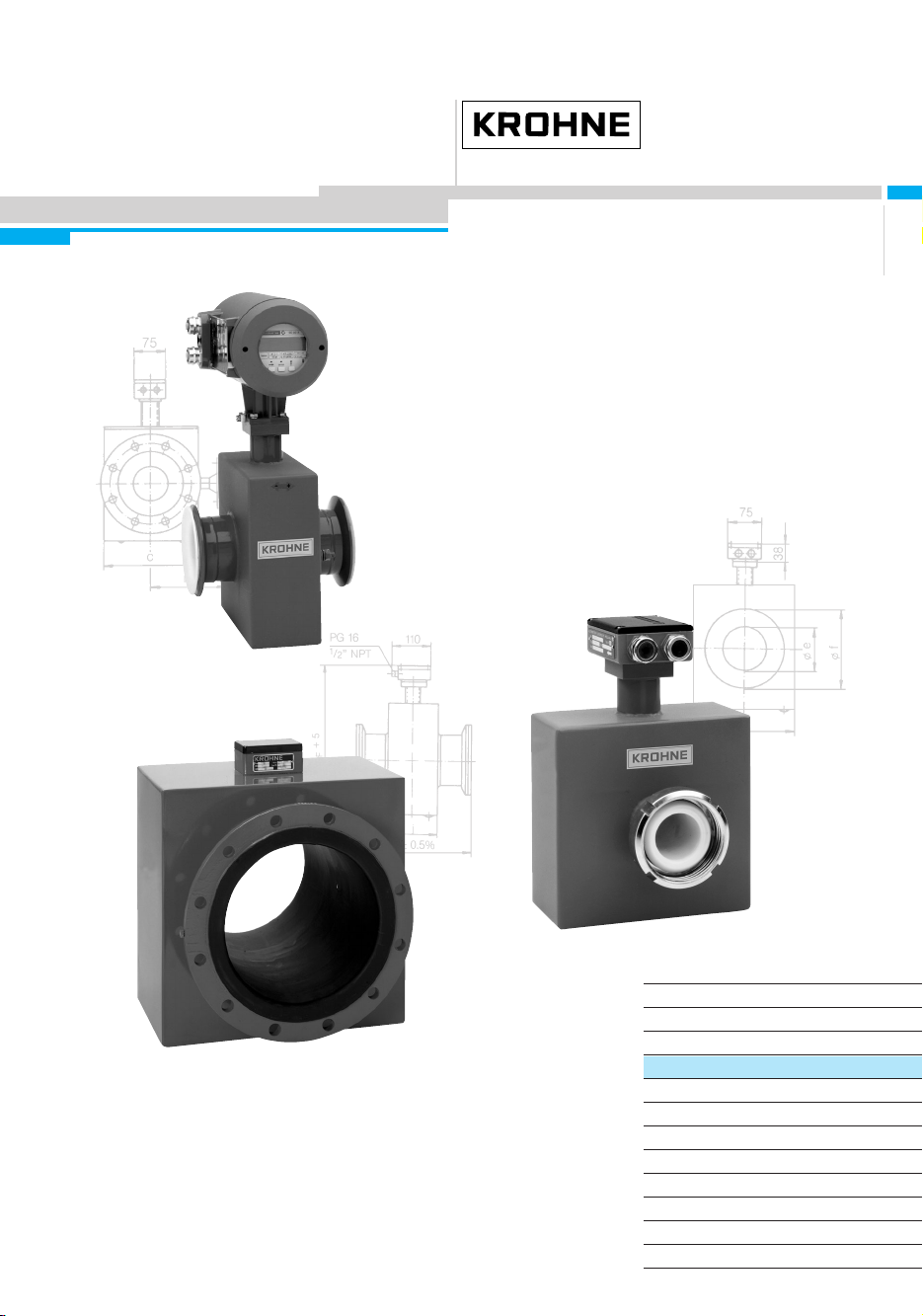
ALTOFLUX M900
ALTOFLUX 3080 K
Electromanetic flowmeters
for particulary applications
GR
How to use these Instructions
The flowmeters are supplied ready for operation.
The primary head must be installed in the pipeline as described in the installation
instructions inside the packing of the primary head.
– Storage and transport Pages 3+4
– Installation in the pipeline Pages 4-5/7-8
– Grounding Page 9
● Primary head
● Compact flowmeters
Variable area flowmeters
Vor tex flowmeters
Flow controllers
Electromagnetic flowmeters
Ultrasonic flowmeters
Mass flowmeters
Level measuring instruments
Communications technology
Engineering systems & solutions
Switches, counters, displays and recorders
Heat metering
Pressure and temperature
DIN A4: 7.10028.31.00
©
KROHNE 03/2003 US size: 7.10028.71.00
Page 2

Contents
System description ...................................................................................................................... 2
Product liability and warranty ..................................................................................................... 2
Standards and approvals ............................................................................................................. 3
Items included with supply........................................................................................................... 3
Handling . ...................................................................................................................................... 3
1 Important information for installation: PLEASE NOTE !.................................................... 4
2 Suggestions for installation ..................................................................................................5
3 Instrument nameplate ............................................................................................................6
4 Flowmeter versions................................................................................................................6
5 Installation in the pipeline ..................................................................................................... 7
6 Torques ...................................................................................................................................8
7 Grounding............................................................................................................................... 9
8 Replacement of the separate primary head ....................................................................... 10
9 Technical data ......................................................................................................................12
10 Dimensions and weights .....................................................................................................14
11 Limits.....................................................................................................................................17
If you need to return flowmeters for testing or repair to KROHNE ........................................ 19
ALTOFLUX electromagnetic flowmeters are precision measuring instruments designed for the
linear flow measurement of process liquids.
The process liquids must be electrically conductive: ≥ 20 µS/cm
The full-scale range Q
ALTOFLUX M900:
DN 10 - 300 /
ALTOFLUX 3080 K:
DN 10 - 300 /
This is equivalent to a flow velocity of 0.3 - 12 m/s, or 1 – 40 ft/s.
3
/8” - 12” Q
3
/8” - 12” Q
can be set as a function of the meter size:
100%
ALTOFLUX electromagnetic flowmeters are designed solely for measuring the volumetric
flowrate of electrically conductive, liquid process products.
Flowmeters with ALTOFLUX primary heads are not certified for use in hazardous locations.
Other flowmeters series are available for such applications.
Responsibility as to suitability and intended use of these electromagnetic flowmeters rests solely
with the operator.
Improper installation and operation of the flowmeters (systems) may lead to loss of warranty.
In addition, the ”General conditions of sale” forming the basis of the purchase contract are
applicable.
If ALTOFLUX flowmeters need to be returned to Krohne, please note the information given on
the last-but-one page of this manual. Krohne regret that they cannot repair or check your
flowmeter(s) unless accompanied by the completed form sheet.
System description
= 0.1 - 3050 m3/hr = 0.37 – 13 440 US GPM
100%
= 0.1 - 3050 m3/hr = 0.37 – 13 440 US GPM
100%
Product liability and warranty
2 Installation and operating instruction ALTOFLUX M900 and 3080 K
Page 3

Standards and approvals
Please refer to the installation and operating instructions for the signal converter.
Items included with supply
ALTOFLUX M900
primary heads
• Primary head in the size as ordered • Compact flowmeter in the size as ordered
• Connecting wires for grounding, refer to
Section 7 “Grounding”
• Certificate of calibration data • Certificate of calibration data
• Grounding rings (optional), if ordered • Grounding rings (optional), if ordered
• Installation instructions • Installation instructions
Fitting accessories (stud bolts, nuts, gaskets, etc.) are not supplied with the flowmeter,
to be provided by customer!
ALTOFLUX 3080 K
compact flowmeters
• Connecting wires for grounding, see
Section 7 “Grounding”
• Installation and operating instructions for the
signal converter
Handling
Do not lift flowmeter by the signal converter
housing or the terminal box.
Do not set flowmeter down on signal converter
housing or terminal box.
PLEASE NOTE
the temperature limits for storage and transport, see Page 4.
Installation and operating instruction ALTOFLUX M900 and 3080 K 3
Page 4
1 Important information for installation: PLEASE NOTE !
• Temperatures
Refer to Section 11 “Limits” for operating pressure and vacuum load based on flange
standards and type of tube liner.
Compact system 3080 K
ALTOFLUX M900 -25 to +60 °C (-13 to +140 °F)
In storage -20 to +60 °C (- 4 to +140 °F), (Neoprene liner)
avoid moisture and sunlight.
Transport - 5 to +50 °C (- 4 to +140 °F), (Neoprene liner)
avoid moisture and sunlight.
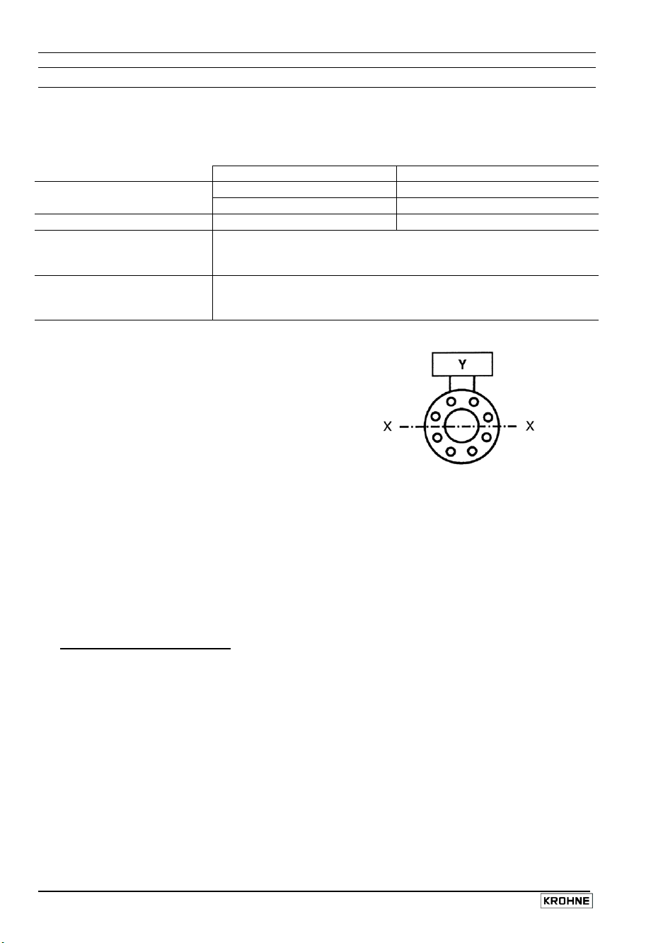
• Location and position as required,
but electrode axis
X – • – • – • – X
must be approximately horizontal in a
horizontal pipe run.
Y terminal box or converter housing
• Measuring tube must be completetly filled at all times.
• Direction of flow is arbitrary. Arrow on flowmeter can normally be ignored. For exceptions,
refer to Section “Factory settings” in the installation and operating instructions for the signal
converter.
• Stud bolts and nuts: to fit, make sure there is sufficient room next to the pipe flanges.
• Vibration: support the pipeline on both sides of the compact flowmeter. Level of vibration in
conformity with IEC 068-2-34: below 2.2g for compact flowmeters in the frequency range of
20-150 Hz with the IFC 090 K.
• Do not expose to direct sunlight, fit a sunshade if necessary, not included with flowmeter,
to be provided by customer.
• Large meter sizes (≥ DN 200 / ≥ 8”), use adapter pipes to allow axial shifting of the
counterflanges and to facilitate installation.
• Strong electromagnetic fields, avoid in vicinity of flowmeter
• Straight inlet run minimum of 5 × DN and outlet run minimum of 2 × DN,
(DN = meter size), measured from the electrode axis.
Ambient temperature Process temperature
-25 to +60 °C (-13 to +140 °F)
-25 to +40 °C (-13 to +104 °F)
-25 to ≤ +60 °C (-13 to ≤ +140 °F)
-25 to > +60 °C (-13 to ≤ +194 °F)
-25 to > +60 °C (-13 to > +140 °F)
-25 bis +60 °C (all other liners)
-25 bis +60 °C (all other liners)
4 Installation and operating instruction ALTOFLUX M900 and 3080 K
Page 5

• Vortex and corkscrew flow: increase length of inlet and outlet runs or install flow
conditioners.
• Mixing different process liquids: install flowmeter upstream of mixing point or at an
adequate distance downstream (minimum of 30 × DN), otherwise display may be unsteady.
• Plastic pipes and internally coated metal pipelines: grounding rings required, see Section 7
“Grounding”.
• Insulated pipeline: do not insulate flowmeter.
• Zero setting not necessary. To check, it should be possible to set “zero” flow velocity in the
completely filled measuring tube. Shutoff valves should therefore be provided either
downstream of the flowmeter or upstream and downstream of the flowmeter.
2 Suggestions for installation
To avoid measuring errors due to gas/air inclusion or to pipe running empty, please observe the
following:
Highest point of pipe run Downpipe over 5 m (16 ft) length
(Air bubbles collect in measuring
tube - faulty measurements!) flowmeter.
Install air valve ✇ downstream of
Preferred
locations
Downpipe
“Zero” flow
velocity.
Line drained.
Faulty
measurements!
Long pipeline
Always install control and shutoff valves
downstream of flowmeter.
Horizontal pipe run
Install in slightly ascending pipe section. If
not possible, assure adequate velocity to
prevent air, gas or vapor from collecting in
uppper part of flow tube.
Pumps
Open feed or discharge Never install flowmeter on pump suction side.
Install meter in low section of pipe.
open discharge
Installation and operating instruction ALTOFLUX M900 and 3080 K 5
Page 6
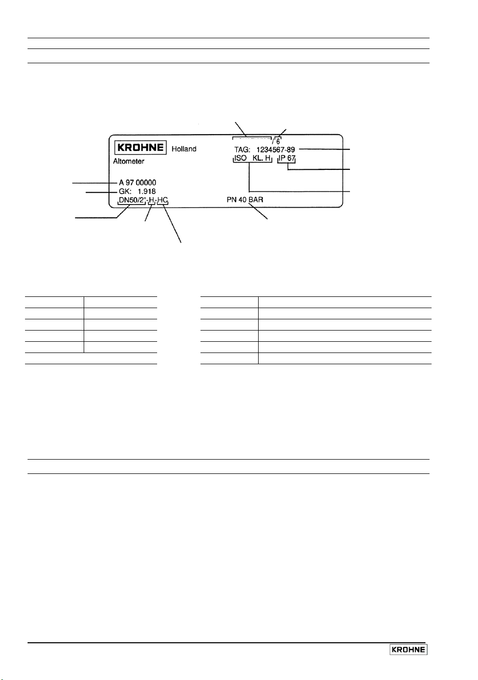
3 Instrument nameplate
ALTOFLUX M900
separate primary head
Series No.
Primary head
constant
Meter size
DN in mm and
inch equivalent
Liner
Hard rubber
Type designation
Electrode material
Hastelloy C4
Magnetic field frequency
(here 1/6 of power frequency)
ALTOFLUX M900
Flange pressure rating
or flange class
Tag No.
Protection category
to IEC 529/EN 60529
Insulation class
of field coils
Liner materials
Electrode materials
H Hard rubber HB Hastelloy B2
NE Neoprene HC Hastelloy C4
PUI Irathane PT Platinum
T Teflon®-PTFE TA Tantalum
W Soft rubber TI Titanium
V4A Stainless steel 1.4571 / SS 316-Ti
®
Teflon
is a registered trademark of Du Pont
Instrument nameplate for compact flowmeters
see installation and operating instructions for the signal converter.
4 Flowmeter versions
ALTOFLUX M900 Separate primary head (F) electrically connected to the signal
converter by signal and field current cables.
ALTOFLUX 3080 K Compact flowmeter (K), IFC 090 K signal converter mounted direct
on the primary head.
Versions for hazardous locations
M900 and 3080 K are approved as electrical equipment to the harmonized European Standards
and to Factory Mutual (FM).
Test certificate, certificate of conformity and wiring instructions for these devices are attached to
the ”Ex” installation instructions, provided only with hazardous-duty equipment.
6 Installation and operating instruction ALTOFLUX M900 and 3080 K
Page 7
5 Installation in the pipeline
• Installation material not included, to be provided by customer (stud bolts,
nuts, gaskets, etc.)
• Pipe flanges and operating pressure: refer to tables on “limits” in Section 11.
• Distance between pipe flanges
see fitting dimension “a”, in Section 10 “Dimensions and weights”.
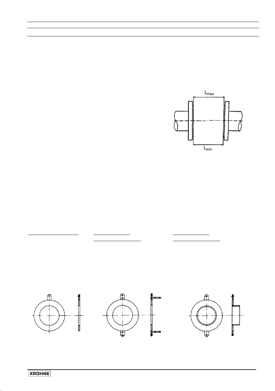
• Position of flanges
Install flowmeter in line with the pipe axis.
Pipe flange faces must be parallel to each other,
max. permissible deviation:
L
- L
- L
≤ 0.5 mm
min
≤ 0.02”
min
protective ring No. 2
Teflon®-PTFE liner,
solidly fitted to the flanges,
3 mm/0.12” thick
Grounding ring,
protective ring No. 3
with cylindrical neck, to protect
the liner particularly at the inlet
edge against abrasive products,
3 mm/0.12” thick
Length:
30 mm/1.18”, for ≤ DN 300, ≤ 12“
100 mm/3.94”, for ≥ DN 350, ≥ 14“
max
L
max
• Hard rubber liner
Please note the table on page 4 for temperature
limits of operation, storage and transport.
• Teflon®-PTFE liner
Install at the lowest point of the pipe run to avoid an excessive vacuum condition atthe meter.
Do not remove or damage liner, which is formed around the flange edges.
• Gaskets
Use gaskets suitable for the application and appropriate to the liner, not included with
flowmeter, to be provided by customer.
• Grounding rings / protective rings (option)
On plastic pipes and internally coated metal pipelines, grounding rings must form the
conductive connection with the fluid. Refer to Section 7 “Grounding for electrical connection.
Grounding ring, No. 1 Grounding ring,
3 mm/0.12” thick for flowmeters with
®
is a registered trademark of Du Pont.
Teflon
Installation and operating instruction ALTOFLUX M900 and 3080 K 7
Page 8

6 Torques
• Tighten
Column A,
•
Column B
•
10 Nm ~ 1.0 kpm ~ 7.23 ft × lbf
•
Meter Pres- Bolts Max. torque
size sure
DN mm PN
10 40 4 x M 12 7.6 (5.5) 4.6 (3.3) 3/8 580 4 x 1/2" 3.5 (2.5) 3.6 (2.6)
15 40 4 x M 12 9.3 (6.7) 5.7 (4.1) 1/2 580 4 x 1/2" 3.5 (2.5) 3.6 (2.6)
20 40 4 x M 12 16 (11.6) 9.6 (6.9) 3/4 580 4 x 1/2" 4.8 (3.5) 4.8 (3.5)
25 40 4 x M 12 22 (15.9) 11 (8.0) 1 580 4 x 1/2" 6.7 (4.8) 4.4 (3.2)
32 40 4 x M 16 37 (26.8) 19 (13.0) 11/2 580 4 x 1/2" 13 (9.4) 12 (8.7)
40 40 4 x M 16 43 (31.1) 25 (18.1) 2 580 4 x 5/8" 24 (17.4) 23 (16.6)
50 40 4 x M 16 55 (39.8) 31 (22.4) 3 360 4 x 5/8" 43 (31.1) 39 (28.2)
65 16 4 x M 16 51 (36.9) 42 (30.4) 4 230 8 x 5/8" 34 (24.6) 31 (22.4)
65 40 8 x M 16 38 (27.5) 21 (15.2) 6 230 8 x 3/4" 61 (44.1) 51 (36.9)
80 25 8 x M 16 47 (34.0) 25 (18.1) 8 145 8 x 3/4" 86 (62.2) 69 (49.9)
100 16 8 x M 16 39 (28.2) 30 (21.7) 10 145 12 x 7/8" 97 (70.2) 79 (57.1)
125 16 8 x M 16 53 (38.3) 40 (28.9) 12 145 12 x 7/8" 119 (86.1) 104 (75.2)
150 16 8 x M 20 68 (49.2) 47 (34.0)
200 10 8 x M 20 84 (60.7) 68 (49.2)
200 16 12 x M 20 68 (49.2) 45 (32.5)
250 10 12 x M 20 78 (56.4) 65 (47.0)
250 16 12 x M 24 116 (83.9) 78 (56.4)
300 10 12 x M 20 88 (63.7) 76 (54.9)
300 16 12 x M 24 144 (104.2) 105 (75.9)
Teflon® is registered trademark of Du Pont
stud bolts
Torques for Teflon
uniformly in diagonally opposite sequence, see table for number and type.
®
-PTFE liner.
, Torques for liner made of Polypropylene and hard rubber.
Meter Body
size pressure
Nm (ft × lbf)
rating
A B
rating
inch psig
Note:
Process pressure must not exceed ANSI
flange rating. Refer to ANSI Standard B 16.5.
Bolts
Max. torque
Nm (ft × lbf)
A
B
8 Installation and operating instruction ALTOFLUX M900 and 3080 K
Page 9

7 Grounding
•
All flowmeters must be properly grounded to avoid personnel shock hazard.
•
The ground conductor should not transmit any interference voltages, therefore do not ground any
other electrical devices together with this conductor.
ALTOFLUX M900
•
An
FE functional ground
•
Signal converter with field power supply > 125 mA / 60 V
connected to the primary head, because of the higher field current from the signal converter. See
grounding diagrams below.
ALTOFLUX 3080 K
Supply power > 50 V AC
•
Grounding is via the
see also Section “Connection to power” in the installation and operating instructions for the signal
converter.
•
EXCEPTION:
if e.g. compact units are operated in the proximity of electric furnaces, electrolysis plants, etc.,
and large potential differences occur in the pipeline system. An FE functional ground must
simultaneously take over the function of the protective conductor (combined protective/functional
ground). Refer to appropriate national codes for specific requirements for this type of installation,
which may require the addition of a ground fault detection circuit interrupter.
Power supply 24 V AC or DC
•
Protective separation (PELV) must be ensured (VDE 0100 / VDE 0106 or IEC 364 / IEC 536 or
equivalent national regulations).
•
An
FE functional ground conductor
Grounding diagrams
grounding without grounding rings grounding with grounding rings
separate primary head with terminal box
must always be connected.
a
PE protective conductor
compact systems
PE protective ground conductor
Do not connect up the PE protective ground conductor in the terminal box
incorporated in the power supply cable,
must be connected for measurement reasons.
Metal pipelines, Metal pipelines,
not internally coated with or without internal coating,
and plastic pipelines
must be
D1, D2, D3 Gaskets, not included with supply, to be provided by customer.
E Grounding rings (option)
F Flowmeter flanges
FE
PE
R Pipeline
RF Pipe flanges
V1, V2 Interconnecting wires, included with flowmeter
Y Terminal box or signal converter
Functional ground, wire
Protective conductor required if the ALTOFLUX M900 is operated with a signal converter that supplies a field current of
> 125 mA / > 60 V. Wire
≥
4 mm2 Cu (10 AWG), not included with flowmeter, to be provided by customer
≥
4 mm2 Cu (10 AWG), not included with flowmeter, to be provided by customer.
Installation and operating instruction ALTOFLUX M900 and 3080 K 9
Page 10

8 Replacement of the separate primary head
Switch off power source before commencing work !
1) Note down terminal assignment before dismantling the “old” primary head.
2) Install the new primary head as described in the supplied installation instructions.
3) Make electrical connection at the signal converter as described in the installation and
operating instructions for the signal converter.
4) Specific calibration data are defined during factory calibration for each primary head, which
are indicated on the instrument nameplate.
This includes the primary constant GK and the magnetic field frequency.
These data need to be reset in the signal converter.
5) If the size of primary head is also different from the old one, the full-scale range Q
meter size will need to be reset.
6) After resetting the signal converter, carry out a zero point check.
7) If necessary, reset the internal electronic totalizer of the signal converter.
100%
and the
10 Installation and operating instruction ALTOFLUX M900 and 3080 K
Page 11

Notes
Installation and operating instruction ALTOFLUX M900 and 3080 K 11
Page 12
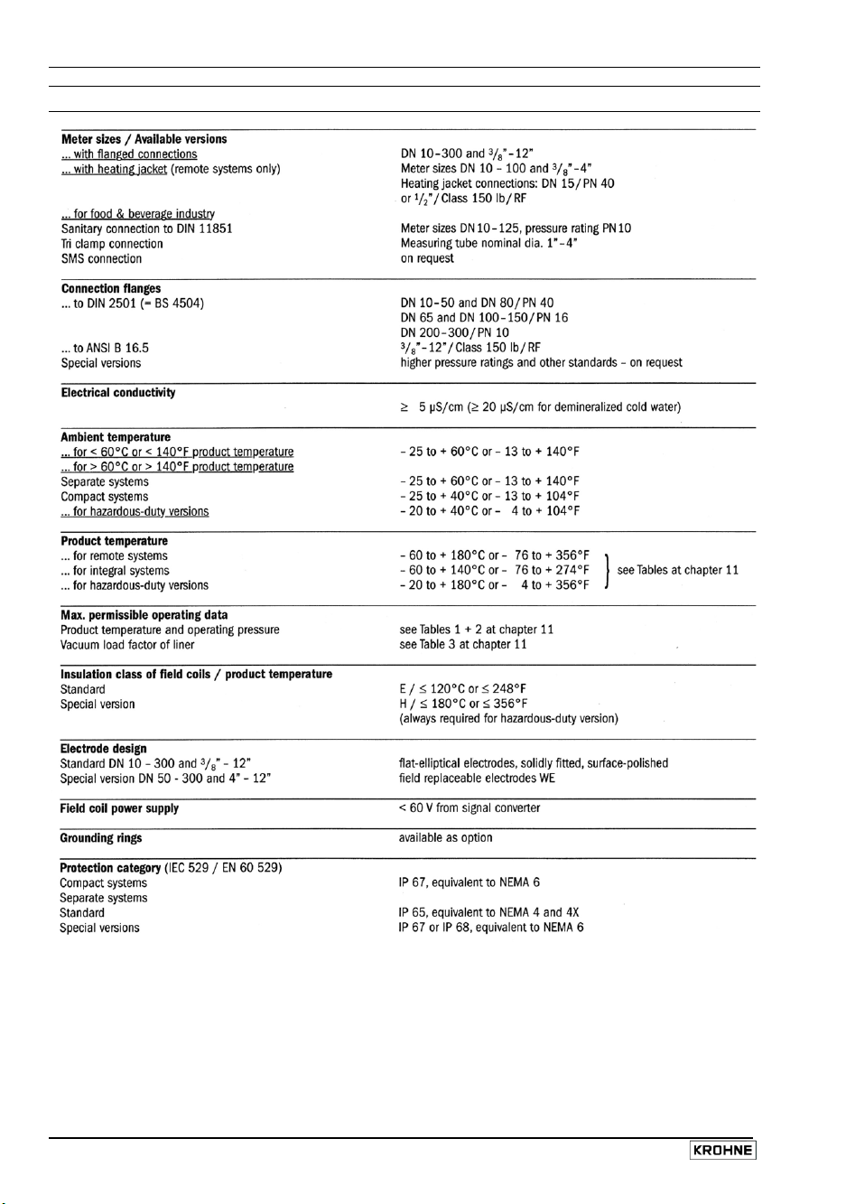
9 Technical data
12 Installation and operating instruction ALTOFLUX M900 and 3080 K
Page 13

Installation and operating instruction ALTOFLUX M900 and 3080 K 13
Page 14

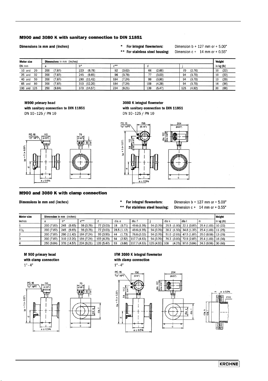
10 Dimensions and weights
14 Installation and operating instruction ALTOFLUX M900 and 3080 K
Page 15

Installation and operating instruction ALTOFLUX M900 and 3080 K 15
Page 16
16 Installation and operating instruction ALTOFLUX M900 and 3080 K
Page 17
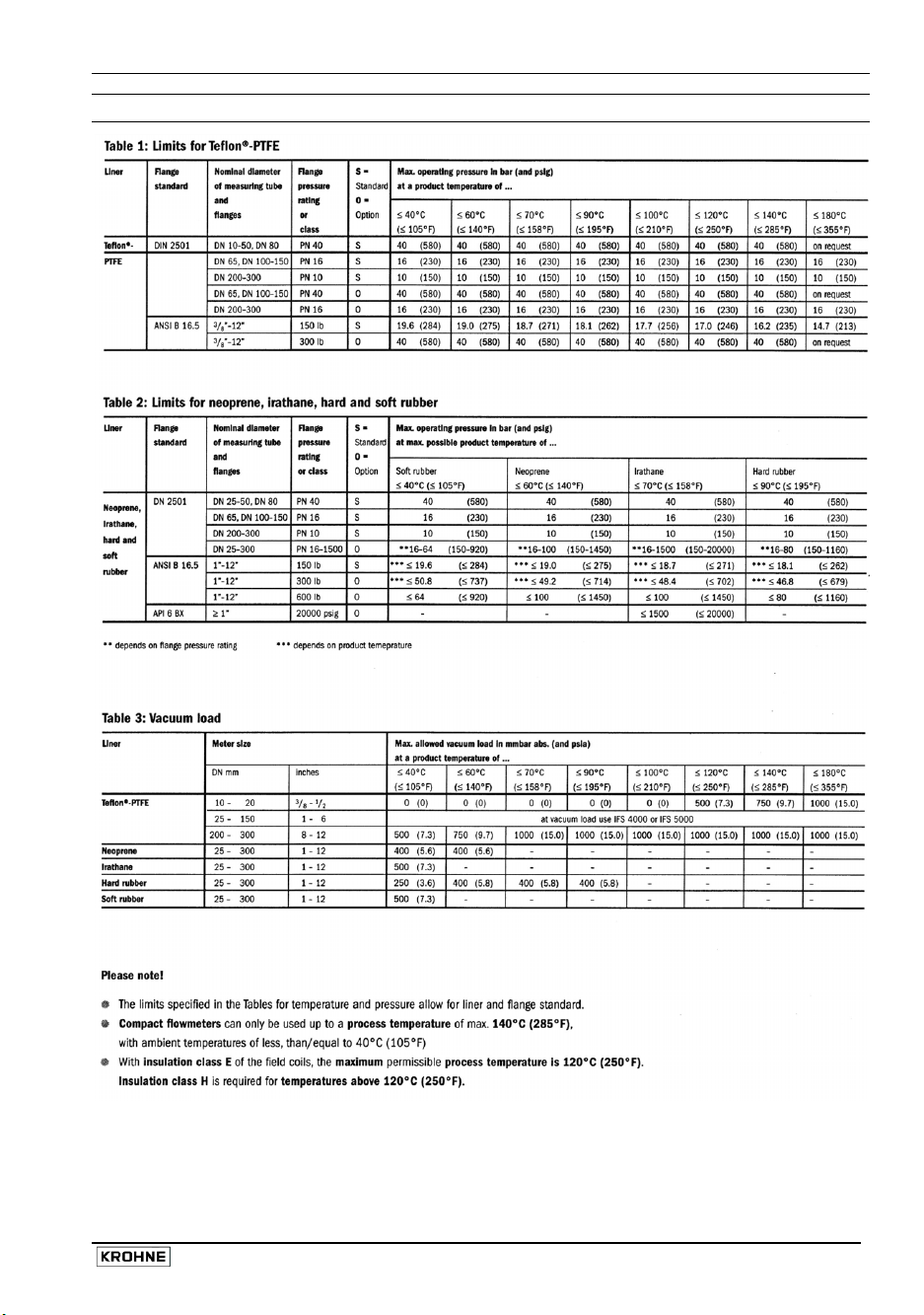
11 Limits
Installation and operating instruction ALTOFLUX M900 and 3080 K 17
Page 18

Notes
18 Installation and operating instruction ALTOFLUX M900 and 3080 K
Page 19

If you need to return flowmeters for testing or repair to KROHNE
Your electromagnetic flowmeter
• has been carefully manufactured and
tested by a company with ISO 9001
certification
• and volumetrically calibrated in one of the
world’s most accurate test rigs.
If installed and operated in accordance with
these operating instructions, your flowmeter
will rarely present any problems.
Should you nevertheless need to return a
flowmeter for checkout or repair, please pay
strict attention to the following points:
Due to statutory regulations concerning
protection of the environment and the health
and safety of our personnel, Krohne may only
handle, test and repair returned flowmeters
that have been in contact with liquids if it is
possible to do so without risk to personnel
and environment. This means that Krohne
can only service your flowmeter if it is
accompanied by a certificate in line with the
following model confirming that the flowmeter is
safe to handle.
If the flowmeter has been operated with toxic,
caustic, flammable or water-endangering
liquids, you are kindly requested
• to check and ensure, if necessary by rinsing
or neutralizing, that all cavities in the
flowmeter are free from suchdangerous
substances.
(Directions on how you can find out whether
the primary head has to be opened and then
flushed out or neutralized are obtainable
from Krohne on request.)
• to enclose a certificate with the flowmeter
confirming that the flowmeter is safe to
handle and stating the liquid used.
KROHNE regret that they cannot service your
flowmeter unless accompanied by such a
certificate.
S P E C I M E N certificate
Company: ……………………………………….. Address: ……………………………………………
Department: …………………………………….. Name: ………………………………………………
Tel. No.: ………………………………………….
The enclosed electromagnetic flowmeter
Type: …………………………………………….. KROHNE Order No. or Series No ………………
has been operated with the following liquid: ……………………………………………………………..
Because this liquid is
water-endangering * / toxic * / caustic * / flammable *
we have
– checked that all cavities in the flowmeter are free from such substances *
– flushed out and neutralized all cavities in the flowmeter *
(* delete if not applicable)
We confirm that there is no risk to man or environment through any residual liquid contained in
this flowmeter.
Date: ………………………….. Signature: ……………………………………………………………..
Company stamp:
Installation and operating instruction ALTOFLUX M900 and 3080 K 19
 Loading...