

Page 1
Installation and
Operating Instructions
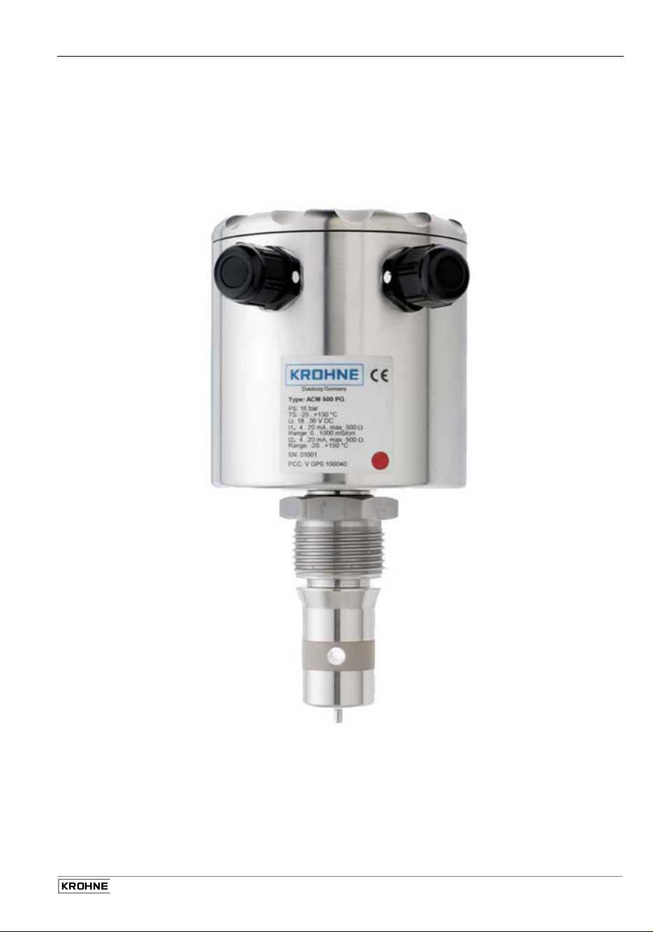
ACM 500
Date: 1.02.2013
02/2013 ACM 500 1
Page 2

Contents
Items supplied .................................................................................................................................... 3
System description ............................................................................................................................ 3
Product liability and warranty ............................................................................................................. 3
CE / EMC / Standards / Approvals ..................................................................................................... 3
1 Installation ............................................................................................................................... 4
1.1 Mechanical installation .............................................................................................................. 4
1.2 Process connection ................................................................................................................... 4
1.3 Mounting of 3A marked products ............................................................................................... 5
2 Electrical connection .............................................................................................................. 6
2.1 Connection plan: ....................................................................................................................... 7
2.2 Start-up ..................................................................................................................................... 7
2.3 Operator control ........................................................................................................................ 7
3 Setting the parameters ........................................................................................................... 8
3.1 Menu structure .......................................................................................................................... 8
3.2 Measured data/version indication 0 ........................................................................................... 9
3.3 Range setting, conductivity 1, 3, 5, 7 ......................................................................................... 9
3.4 Setting of temperature compensation 2, 4, 6, 8 ....................................................................... 10
3.5 Measuring range setting, temperature 9 .................................................................................. 11
4 Maintenance / Error handling ............................................................................................... 12
4.1 Error displays .......................................................................................................................... 12
4.1.1Overranging of the conductivity measuring range ................................................................... 12
4.1.2Overranging of ADC conductivity ............................................................................................ 12
4.1.3Error in conductivity measurement .......................................................................................... 12
4.1.4Overranging of the ADC for temperature ................................................................................. 13
5 Safety information ................................................................................................................. 13
6 Technical data extract ........................................................................................................... 14
6.1 Dimensions ............................................................................................................................. 14
7 Type code .............................................................................................................................. 15
7.1 Ordering code ......................................................................................................................... 15
7.2 Spare parts .............................................................................................................................. 15
7.3 Accessories ............................................................................................................................. 15
8 Product description .............................................................................................................. 16
8.1 Range of application ................................................................................................................ 16
8.2 Functional principle ................................................................................................................. 16
8.3 Configuration ........................................................................................................................... 16
8.4 Features .................................................................................................................................. 17
9 Notes ...................................................................................................................................... 18
If you need to return a device for testing or repair to KROHNE ....................................................... 19
2
ACM 500 02/2013
Page 3
Items supplied
• Measuring instrument
• Hygienic adapter
• Installation and operating instructions
System description
Inputting physical quantities into an SPC or PLC control or other computer and control systems
requires accurate and reliably working sensors. The sensor is a detecting element that converts
physical quantities, such as temperature, level, pressure, conductivity, turbidity and flow, into an
electrical signal. Locally further processed, usually with an integrated microcontroller, the measuring
signal can be transmitted by analogue (e.g. 4..20 mA loop) or digital (e.g. Profibus PA) means.
Product liability and warranty
Responsibility as to suitability and intended use of this instrument rests solely with the operator.
Improper installation and operation of the instrument / system may lead to loss of warranty.
In addition, all claims are subject to the “General terms and conditions of sale” under which this
instrument was purchased.
If a meter or instrument needs to be returned to KROHNE, please note the information given on the
last-but-one page of these Instructions.
KROHNE regrets that it cannot repair or check your instruments unless accompanied by a fully
completed Service and Repair sheet.
CE / EMC / Standards / Approvals
The product bears the CE marking on account of compliance with and application of the following
standards:
EMCG (89/336/EEC)
EN 50081-1 EN 55022 Class B
EN 61000-6-2 EN 61000-4-2 ESD 4/8 kV
EN 61000-4-3 RF radiated 10 V/m
EN 61000-4-4 Burst 4 kV
EN 61000-4-5 Surge 1 kV sym., 2 kV unsym.
EN 61000-4-6 RF cable 10 V
02/2013 ACM 500 3
Page 4

1 Installation
1.1 Mechanical installation
Use only the recommended sleeves or adapters. When installed with foreign adapters, no
guarantee can be given for proper functioning or leak-tightness.
Do not use Teflon or paper gaskets.
When installing in pipes, it is advisable to align the bore at the sensor in the direction of flow. This
will ensure good exchange of the medium and good cleanability. The display unit is then
positioned at right angles to the pipe. It is not possible to turn the display relative to the channel
bore!
Carefully introduce the measuring head straight into the sleeve. Hold the correctly aligned
measuring head firmly and screw down the union nut with a tightening torque between 20 and 50
Nm.
Correction inputs as a factor of the diameter are not necessary when installing in pipes.
1.2 Process connection
The hygienic ½” process sleeve is easy to weld in into tanks or pipes. The kind of assembly allows
installation in conformity with standards of hygiene (to EHEDG, FDA). The G1/2” and G1”
connections can be mounted in any counter thread acc. to ISO 228.
Various hygienic adapter sleeves (refer to chapter “Accessories”) are available for fitting to other
process connections. For more information refer to data sheet “Accessories”.
4
ACM 500 02/2013
Page 5
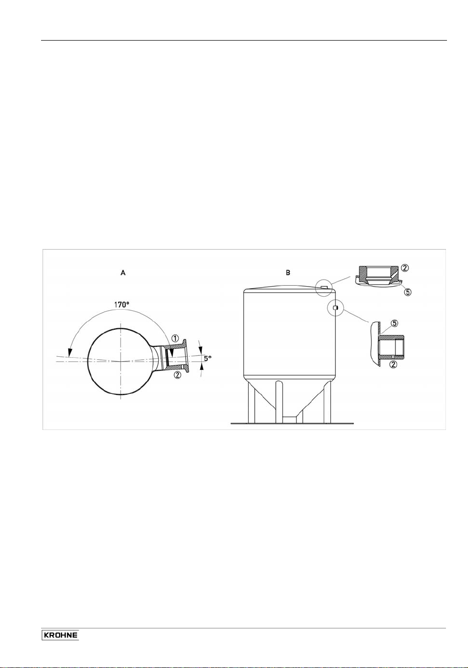
1.3 Mounting of 3A marked products
The 3A mark is valid only when the product is mounted in a 3A marked counterpart and installed acc.
to the installation manual. Use also a 3A marked O-ring or gasket if relevant.
The 3A marked products conforms to the 3A sanitary standards criteria. Materials and surfaces fulfil
the FDA demands and are certified by EHEDG.
EPDM O-rings supplied with 3A marked products are conform to sanitary standards class II (8% milk
fat).
1) Use only 3A approved counterparts
2) The inspection hole should be visible and drained. Face it downwards that leaking can be
observed.
3) Mount the device in a self-drained position.
4) Level the inner surface of the pipe with the counterpart.
5) Weld from the inside of the tank, if possible. Welds shall be free from cracks, crevices
and grooves. Weldings should be grinded to Ra= 0.8
Mounting of 3A products in pipe installations (A) or tank installations (B)
02/2013 ACM 500 5
Page 6
2 Electrical connection
Terminals 1(+) and 2(-) are used for supplying a DC voltage of 18...36V. Terminal 2 is connected
to the housing via a protective diode. The maximum power consumption is 180 mA. This value
should be taken into account for the recommended fuse. An active 4...20 mA current output,
galvanically isolated from the supply voltage, is available at each of terminals 3 and 4, and 5 and
6. Terminal pair 3/4 supplies the conductivity signal, terminal pair 5/6 the temperature value. The
negative terminals of current outputs 4 and 6 are connected to each other internally. 24-V control
signals (pnp) can be connected to terminals 7 (R2) and 8 (R1) for external selection of one of the
four adjustable measuring ranges. The ground reference is connected to terminal 2; an open
terminal signifies 0 V.
Meas. Range R2 R1
1 0 V 0 V
2 0 V 24 V
3 24 V 0 V
4 24 V 24 V
Please note currently valid installation regulations.
6
ACM 500 02/2013
Page 7

2.1 Connection plan:
2.2 Start-up
• Check that the display unit is correctly aligned; it should where possible be perpendicular to
the direction of flow (for pipes).
• Check the leak-tightness at the sleeve.
• Make sure that the cable glands are tight and the M12 plugs are properly bolted.
• Without selection of the measuring range and without parameter assignment by user, the
device after connection to the supply voltage will operate in the measuring range 0...200 mS,
0...150°C und 2%/K.
• Make sure that the housing cover is screwed down tight.
2.3 Operator control
• The back-lit LC display generally indicates conductivity in millisiemens per centimetre
(mS/cm) and temperature in degrees Celsius (°C).
• For simple parameterization of the measuring ranges and temperature coefficients, use the
rotary button with touch function (jog shuttle). Turn it to the right (or left) to move forwards
(backwards) in the menu structure and increase (decrease) parameter values. Press the
button to get to the submenu or setting menu for the respective parameter, or back again
simultaneously with confirmation of the input.
02/2013 ACM 500 7
Page 8

3 Setting the parameters
3.1 Menu structure
For a description of the respective menu screens please follow the two-digit numbering in these
Instructions. The second digit indicates whether the display menu (x0) or the relevant
submenu/setting menu (x1) is meant.
00 Display 117.9 ms
1 25.4 °C
01 Software version V 1.00
10 Meas. Range 1 1 4...20 mA
0...200 mS
11 Meas. Range 11 1 4...20 mA
20 TC 1 1 117.9 ms
2.00%/K
21 Temp. Setup 21 1 117.9 ms
30 Meas. Range 2 2 4...20 mA
0...20 mS
31 Meas. Range 31 1 4...20 mA
40 TC 2 2 10.79 mS
2.50%/K
41 Temp. Setup 41 1 117.9 ms
50 Meas. Range 3 3 4...20 mA
0...2 mS
51 Meas. Range 51 1 4...20 mA
60 TC 3 3 1.567 mS
1.50%/K
61 Temp. Setup 61 1 117.9 ms
70 Meas. Range 4 4 4...20 mA
0...0.5 mS
71 Meas. Range 71 1 4...20 mA
80 TC 4 4 0.335 mS
0...0.00%/K
81 Temp. Setup 81 1 117.9 ms
90 Temp. Range 4...20 m°C
0...150
91 Temp. Range 4...20 m°C
0...200 mS
2.00%/K
0...200 mS
2.00%/K
0...200 mS
2.00%/K
0...200 mS
2.00%/K
0...150
8
ACM 500 02/2013
Page 9

3.2 Measured data/version indication 0
Standard indication of conductivity and temperature. If no input is made, automatic return to
measured data indication after 60 seconds.
The bottom left digit indicates the measuring range 1…4 that has been selected via control inputs
R2 and R1.
117.9 ms
25.4 °C
1
Measured conductivity
Measured temperature
00
External meas. Range option 1....4
V 1.00
01
Software version
Submenu 01 indicates the implemented software version.
3.3 Range setting, conductivity 1, 3, 5, 7
The measuring ranges 1...4 selected via control inputs R2 and R1 are indicated and set here,
referred to the current output range of 4...20 mA.
Meas. range No.
4..20 mA
1
0... mS
Setting meas. range conductivity
for 4...20 mA
Meas. range No.
4..20 mA
1
0... mS
^
v
10
30
50
70
11
31
51
71
Setting meas. range conductivity
for 4...20 mA (with Jog Shuttle)
02/2013 ACM 500 9
Page 10

Adjustable measuring ranges conductivity:
No. Range Resolution
1 0... 0.5 ms 0.001 ms
2 0... 1 ms 0.001 ms
3 0... 2 ms 0.010 ms
4 0... 3 ms 0.010 ms
5 0... 5 ms 0.010 ms
6 0... 10 ms 00.10 ms
7 0.. . 20 ms 00.10 ms
8 0... 30 ms 00.10 ms
9 0... 50 ms 00.10 ms
10 0...100 ms 000.1 ms
11 0...200 ms 000.1 ms
12 0...300 ms 000.1 ms
13 0...500 ms 000.1 ms
14 0...999 ms 000.1 ms
Ranges set in as-delivered condition:
Meas. range mS
1 0...200
2 0...20
3 0...2
4 0...0.5
3.4 Setting of temperature compensation 2, 4, 6, 8
Each measuring range is assigned its own setting for temperature compensation. The range is
adjustable between 0%/K (no compensation) and max. 5%/K. The compensation calculator
operates linearly on the basis of a reference temperature of 25°C. When supplied, the setting for
all ranges is 2%/K.
Meas. range No.
20
mS
1
0... %/K
Setting temperature coefficient
Meas. range No.
mS
1
%/K
^
v
Setting for TC 0...5.0 %/K
(with Jog Shuttle)
10
ACM 500 02/2013
Measured conductivity
40
60
80
21
Measured conductivity
41
61
81
Page 11

Directions for setting the temperature compensation:
• The actual conductivity measured is indicated in the setting menu. This allows easy laboratory
determination of the temperature coefficient (TC) of a liquid:
- Dip the device measuring head in the sample liquid (making sure there are no gas
bubbles in the channel bore).
- Heat the sample to exactly 25.0°C, if possible.
- Note down the indicated conductivity (ensure adequate modulation, adjust measuring
range if necessary).
- Heat the liquid to a minimum of 60°C.
- Set the TC in the setting menu to indicate the same conductivity as at 25°C. Bear in mind
that a higher TC value will give a lower conductivity indication.
• Do not use the TC setting to adjust a measured value. The device is precisely calibrated and
requires no further adjustment. Should you establish variations in the laboratory, please check
whether there are any gas bubbles in the channel bore. If so, dip the device at an incline or
move it quickly in the liquid.
• If there is no movement of the liquid, there may be slight warming in the channel bore by way
of the device which can lead to a slightly falsified indication. Move the device slightly in the
sample liquid if you wish to obtain very accurate reference measurements.
3.5 Measuring range setting, temperature 9
This is used for setting the current output of the measured temperature, based on 4...20 mA. This
setting is provided only once and cannot be changed externally. In as-delivered condition, the
range selected is 0...150°C. The current output follows under- and overranging of the selected
measuring range up to 10%, i.e. from 2.4 mA to 21.6 mA within the limits of
–20°C...150°C.
The selected setting has no effect on temperature indication.
4..20 m°C
.............
90
Setting meas. range temperature
for 4...20 mA
4.....20 m°C
.............
^
v
91
Setting meas. range temperature
for 4...20 mA (with Jog Shuttle)
Adjustable measuring ranges temperature:
No. Range Resolution
1 0...150 °C 0.001 °C
2 -20...130 °C 0.001 °C
3 0...100 °C 0.001 °C
4 -20...80 °C 0.001 °C
5 0...50 °C 0.001 °C
6 -10...40 °C 0.001 °C
7 -20...150 °C 0.001 °C
02/2013 ACM 500 11
Page 12

4 Maintenance / Error handling
4.1 Error displays
The measuring device is self-monitoring for errors and plausibility. The indication in the display
supplies information about possible error conditions. The current outputs, too, are controlled in the
event of an error.
4.1.1 Overranging of the conductivity measuring range
Up to 21.6 mA, the current output follows linearly to the measured value (overrange). Therefore, if
the measured conductivity exceeds the set measuring range by more than 10%, the current output
remains within the limits.
This can be remedied by selecting a larger measuring range. Please also note that at
temperatures below 25°C the temperature compensation will always calculate larger conductivity
values.
Current output: overrangingofconductivity
^ 231.6 mS
25.4 °C
1
Measured conductivity
Measured temperature
00
4.1.2 Overranging of ADC conductivity
At high temperatures and a high temperature coefficient it is possible that the ADC will overrange,
in which case the current output will output an error value of 21.6 mA.
In such a case, select a measuring range from the next-higher decade.
Overranging of conductivity
^^^^.^ mS
25.4 °C
1
Measured conductivity
Measured temperature
00
4.1.3 Error in conductivity measurement
At temperatures above 130°C, the device may in certain circumstances not be able to measure
conductivity any more. The current output then goes to the error value of 2.4 mA. Should this
condition occur at lower temperatures, this means that the device has an internal defect.
Conductivity error
vvv.v mS
25.4 °C
1
Measured conductivity
Measured temperature
00
12
ACM 500 02/2013
Page 13

4.1.4 Overranging of the ADC for temperature
Independent of the measuring range setting for temperature, this is always measured in the –
20...150°C range. Outside these limits the device will go into error condition. Since conductivity
can no longer be compensated, the current output for conductivity will also indicate the error
condition with 2.4 mA. The current value for temperature will, depending on whether under- or
overranging has occurred, go to 2.4 mA and 21.6 mA, resp.
If this error occurs within the permissible temperature range, this would suggest that the
temperature sensor is defective.
Temperature > 150°C
^^^^.^ mS
^^^.^ °C
1
Measured conductivity
Measured temperature
00
Temperature < -20°C
^^^^.^ mS
°C
1 vv.v
Measured conductivity
Measured temperature
00
5 Safety information
Before putting the device into operation, please read through this product description. Make sure
that the product is unconditionally suitable for the application in question.
Disregard of application directions or technical details can lead to personal injury and/or damage
to property.
In all applications, make sure the materials of construction (see Technical Data) are compatible
with the media to be measured.
For start-up and operation, please pay regard to the following information. In addition, consult
national installation regulations and the safety and accident prevention regulations applicable to
the respective application.
02/2013 ACM 500 13
Page 14

6 Technical data extract
Temperature range –20...+130 °C, 140 °C < 60 min.
Operating pressure max. 10 bar
Inputs 2 x 24-V control input (pnp); 18 V ... 36 V
Outputs 2 x 4...20 mA active galv. sep.; load max. 500 Ohm
Repeatability, cond. < ±1% of full-scale range
Accuracy, temp.
< ±0.2 °C (0...50 °C), ≤ ±0.5 °C (-20...150 °C)
Response time, temp. T 90 < 4.5 s
Voltage supply 18...36 V DC; 180 mA max.
6.1 Dimensions
14
ACM 500 02/2013
Page 15

7 Type code
7.1 Ordering code
Ordering code
0 Cable gland M16
4 Plug M12
4 Cable gland M16
6 Plug M12
V GP0 10004
Length of measuring head from edge of sleeve 37 mm
Electrical connection
Length of measuring head from edge of sleeve 84 mm
Electrical connection
7.2 Spare parts
Should a replaceable part of the probe be lost or damaged, replacements can be ordered on the
basis of the part number.
Designation Type
Housing lid KMD.016.090.010
Cable gland M16 KVV.M16.010.008
Connector inlet KVV.100.004.000
connector KVK.086.210.018
7.3 Accessories
Designation Type
Weld in sleeve HWN 500 VGP7000100
Varivent flange version N VGP7000C00
Sanitary pipe assembly kit DN 50 VGP7000B00
Tri-Clamp flange DN 32, DN 40, 2" VGP7000D00
02/2013 ACM 500 15
Page 16

8 Product description
8.1 Range of application
The compact inductive conductivity sensor allows determination of the electrical conductivity of
liquids. The small size of the measuring head allows installation in pipes sized DN40 and higher.
The high-sensitivity resolution of 1 µS/cm together with a fast response time ensures reliable
detection of media even with only minor differences in conductivity (e.g. beer – beer).
8.2 Functional principle
Inductive conductivity measurement is based on the principle of two series-connected toroidalcore transformers. The primary side of the first transformer (2) is controlled by an AC voltage
generator (1).
The link between the secondary side of the first transformer and the primary side of the second
transformer (4) is formed by the conductor loop, which in turn is formed by the liquid flowing
through the channel bore in the measuring head (3). The better the conductivity of the liquid, the
greater is the measurable current on the secondary side of the second transformer. This signalling
current is processed by a measuring amplifier (6), is digitized (7), further processed by a
microcontroller (8), and forwarded to the digital-to-analogue converter of the galvanically isolated
current output stage (9).
The fast-response precision temperature sensor (5) in the tip of the measuring head is used for
computational compensation of the heavily temperature-dependent conductivity of liquids.
The specially developed signal processing unit (patent applied for) revolutionizes the classic
functional principle and offers you maximum accuracy and reliability.
8.3 Configuration
The associated weldable sleeve of stainless steel ensures installation conforming to hygiene
standards. The evaluation electronics are fully integrated in the stainless steel connection head.
It supplies a 4...20-mA signal, galvanically isolated from supply, for the measured values of
conductivity and temperature. The integrated display unit, together with the jog-shuttle (control
button with turn and touch function), allows simple local assignment of parameters. Measured data
can be read at all times through the viewing window in the screw-down cover.
16
ACM 500 02/2013
Page 17

8.4 Features
• Compact design with stainless steel housing
• Integrated electronics
• 4 measuring ranges, user-definable via BCD code, external changeover facility
• Temperature compensation, separately adjustable for each measuring range
• Fast response time
• Insensitive to polarization and soiling
• Heat-resistant up to 130°C, for short times up to 140°C
• Integral display unit for measured data indication and parameter assignment
• Easy to operate with jog-shuttle
• Hygienic adapter sleeves for various process connections
02/2013 ACM 500 17
Page 18

9 Notes
18
ACM 500 02/2013
Page 19

.
If you need to return a device for testing or repair to KROHNE
Your instrument has been carefully manufactured and tested. If installed and operated in
accordance with these operating instructions, it will rarely present any problems. Should you
nevertheless need to return an instrument for servicing or repair, please pay strict attention to the
following points:
Due to statutory regulations on environmental protection and safeguarding the health and safety of
our personnel, KROHNE may only handle, test and repair returned instruments that have been in
contact with liquids if it is possible to do so without risk to personnel and environment.
This means that KROHNE can only service your instrument if accompanied by the following
certificate confirming that the instrument is safe to handle. If the instrument has been operated with
toxic, caustic, flammable or water-endangering liquids, you are kindly requested
• to check and ensure, if necessary by rinsing or neutralising, that all cavities in the instrument
are free from such dangerous substances.
(Directions on how you can find out whether the primary head has to be opened and flushed
out or neutralised are obtainable from KROHNE on request.)
• to attach a certificate to the instrument confirming that the instrument is safe to handle and
stating the liquid used.
We cannot service your instrument unless accompanied by such a certificate.
Specimen certificate
Company: Address:
Department: Name:
Tel. No.: Fax No.:
The enclosed instrument
Type: .:
KROHNE Order No. or Series No
has been operated with the following process liquid
Because this process liquid is
water-hazardous toxic caustic flammable
*
we have
checked that all cavities in the instrument are free from such substances *
flushed out and neutralised all cavities in the instrument *
We confirm that there is no risk to humans or environment through any residual liquid contained in
the instrument.
Date: .....................................................................Signature .............................................................
.............................................................................
Company stamp:
02/2013 ACM 500 19
 Loading...