

Page 1
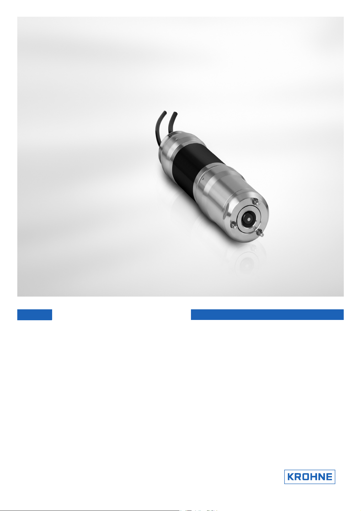
OPTISENS AAS 2000
OPTISENS AAS 2000
OPTISENS AAS 2000OPTISENS AAS 2000
Dissolved Oxygen Sensor
Handbook
Handbook
HandbookHandbook
Page 2

: IMPRINT
:::::::::::::::::::::::::::::::::::::::::::::::::::::
OPTISENS AAS 2000
All rights reserved. It is prohibited to reproduce this documentation, or any part thereof, without
the prior written authorisation of KROHNE Messtechnik GmbH & Co. KG.
Subject to change without notice.
Copyright 2008 by
KROHNE Messtechnik GmbH & Co.KG - Ludwig-Krohne-Straße 5 - 47058 Duisburg
2
www.krohne.com 12/2008 • MA AAS 2000 R01 en
Page 3

OPTISENS AAS 2000
1 Safety instructions......................................................................... 5
1.1 Intended Use ........................................................................................................ 5
1.2 Safety instructions from the manufacturer......................................................... 5
1.2.1 Copyright and data protection................................................................................... 5
1.2.2 Disclaimer.................................................................................................................. 5
1.2.3 Product liability and warranty ...................................................................................6
1.2.4 Information concerning the documentation .............................................................6
1.2.5 Display conventions................................................................................................... 7
1.3 Safety instructions for the operator .................................................................... 7
2 Device description ......................................................................... 8
2.1 Scope of delivery .................................................................................................. 8
2.2 Device description................................................................................................ 9
2.2.1 Design ........................................................................................................................ 9
2.3 Nameplates........................................................................................................ 10
2.3.1 OPTISENS AAS 2000 ................................................................................................10
CONTENTS
3 Installation................................................................................... 11
3.1 Notes on installation.......................................................................................... 11
3.2 Storage & Transport .......................................................................................... 11
3.3 Installing or changing the electrode ................................................................. 12
3.4 Mounting of the sensor ...................................................................................... 15
3.4.1 Mounting to MAA 2000 telescopic rod immersion holder ...................................... 15
3.4.2 Mounting to MAA 2000 slide rail immersion holder ...............................................18
3.5 Removing the sensor ......................................................................................... 19
4 Electrical connections ................................................................. 21
4.1 Safety instructions ............................................................................................. 21
4.2 Cable connections.............................................................................................. 21
5 Operation ..................................................................................... 22
5.1 Sensor display.................................................................................................... 22
5.2 Menu................................................................................................................... 22
5.3 Calibration.......................................................................................................... 25
5.3.1 Zero calibration ....................................................................................................... 25
5.3.2 Air calibration ..........................................................................................................25
5.4 Scaling................................................................................................................ 27
6 Service......................................................................................... 28
6.1 Cleaning ............................................................................................................. 28
6.1.1 Cleaning the sensor................................................................................................. 28
6.1.2 Cleaning the flushing nozzle ................................................................................... 29
6.2 Spare parts availability ...................................................................................... 30
6.3 Availability of services........................................................................................ 30
6.4 Support information form.................................................................................. 31
www.krohne.com12/2008 • MA AAS 2000 R01 en
3
Page 4

CONTENTS
6.5 Returning the device to the manufacturer ........................................................ 32
6.5.1 KROHNE representative.......................................................................................... 32
6.5.2 General information ................................................................................................ 32
6.5.3 Form (for copying) to accompany a returned device .............................................. 33
6.6 Disposal.............................................................................................................. 33
7 Technical data ............................................................................. 34
7.1 Measuring principle ........................................................................................... 34
7.2 Technical data.................................................................................................... 34
7.3 Dimensions and weight...................................................................................... 36
8 Appendix...................................................................................... 37
8.1 Setup information form ..................................................................................... 37
9 KROHNE measuring technology - Product overview................... 40
OPTISENS AAS 2000
4
www.krohne.com 12/2008 • MA AAS 2000 R01 en
Page 5

OPTISENS AAS 2000
1.1 Intended Use
The OPTISENS AAS 2000 sensors are used to measure the concentration of dissolved oxygen in
water. They can be used in municipal and industrial waste water treatment facilities, water
monitoring stations and other applications.
1.2 Safety instructions from the manufacturer
1.2.1 Copyright and data protection
The contents of this document have been created with great care. Nevertheless, we provide no
guarantee that the contents are correct, complete or up-to-date.
The contents and works in this document are subject to German copyright. Contributions from
third parties are identified as such. Reproduction, processing, dissemination and any type of use
beyond what is permitted under copyright requires written authorisation from the respective
author and/or the manufacturer.
SAFETY INSTRUCTIONS 1
The manufacturer tries always to observe the copyrights of others, and to draw on works created
in-house or works in the public domain.
The collection of personal data (such as names, street addresses or e-mail addresses) in the
manufacturer's documents is always on a voluntary basis whenever possible. Whenever
feasible, it is always possible to make use of the offerings and services without providing any
personal data.
We draw your attention to the fact that data transmission over the Internet (e.g. when
communicating by e-mail) may involve gaps in security. It is not possible to protect such data
completely against access by third parties.
We hereby expressly prohibit the use of the contact data published as part of our duty to publish
an imprint for the purpose of sending us any advertising or informational materials that we have
not expressly requested.
1.2.2 Disclaimer
The manufacturer will not be liable for any damage of any kind by using its product, including,
but not limited to direct, indirect, incidental, punitive and consequential damages.
This disclaimer does not apply in case the manufacturer has acted on purpose or with gross
negligence. In the event any applicable law does not allow such limitations on implied warranties
or the exclusion of limitation of certain damages, you may, if such law applies to you, not be
subject to some or all of the above disclaimer, exclusions or limitations.
www.krohne.com12/2008 • MA AAS 2000 R01 en
5
Page 6

1 SAFETY INSTRUCTIONS
Any product purchased from the manufacturer is warranted in accordance with the relevant
product documentation and our Terms and Conditions of Sale.
The manufacturer reserves the right to alter the content of its documents, including this
disclaimer in any way, at any time, for any reason, without prior notification, and will not be liable
in any way for possible consequences of such changes.
1.2.3 Product liability and warranty
The operator shall bear responsibility for the suitability of the device for the specific purpose.
The manufacturer accepts no liability for the consequences of misuse by the operator. Improper
installation and operation of the devices (systems) will cause the warranty to be void. The
respective "Standard Terms and Conditions" which form the basis for the sales contract shall
also apply.
OPTISENS AAS 2000
1.2.4 Information concerning the documentation
To prevent any injury to the user or damage to the device it is essential that you read the
information in this document and observe applicable national standards, safety requirements
and accident prevention regulations.
If this document is not in your native language and if you have any problems understanding the
text, we advise you to contact your local office for assistance. The manufacturer can not accept
responsibility for any damage or injury caused by misunderstanding of the information in this
document.
This document is provided to help you establish operating conditions, which will permit safe and
efficient use of this device. Special considerations and precautions are also described in the
document, which appear in the form of underneath icons.
6
www.krohne.com 12/2008 • MA AAS 2000 R01 en
Page 7
OPTISENS AAS 2000
1.2.5 Display conventions
The following symbols are used to help you navigate this documentation more easily:
DANGER!
This symbol designates safety advice on handling electricity.
WARNING!
These warning signs must be observed without fail. Even only partial disregarding such
warnings can result in serious health damage, damage to the device itself or to parts of the
operator
CAUTION!
These warnings must be observed without fail. Even only partial disregarding such warnings can
lead to improper functioning of the device.
’
s plant.
SAFETY INSTRUCTIONS 1
LEGAL NOTICE!
This symbol designates information on statutory directives and standards.
INFORMATION!
This symbol designates important information for the handling of the device.
• HANDLING
HANDLING
HANDLINGHANDLING
This symbol designates all instructions for actions to be carried out by the operator in the
specified sequence.
i CONSEQUENCE
CONSEQUENCE
CONSEQUENCECONSEQUENCE
This symbol designates all important consequences of the previous actions.
1.3 Safety instructions for the operator
WARNING!
In general, devices from the manufacturer may only be installed, commissioned, operated and
maintained by properly trained and authorized personnel.
This document is provided to help you establish operating conditions, which will permit safe and
efficient use of this device.
www.krohne.com12/2008 • MA AAS 2000 R01 en
7
Page 8
2 DEVICE DESCRIPTION
2.1 Scope of delivery
INFORMATION!
Inspect the cartons carefully for damage or signs of rough handling. Report damage to the
carrier and to the local office of the manufacturer.
INFORMATION!
Check the packing list to check if you received completely all that you ordered.
INFORMATION!
Look at the device nameplate to ensure that the device is delivered according to your order.
Check for the correct supply voltage printed on the nameplate.
OPTISENS AAS 2000
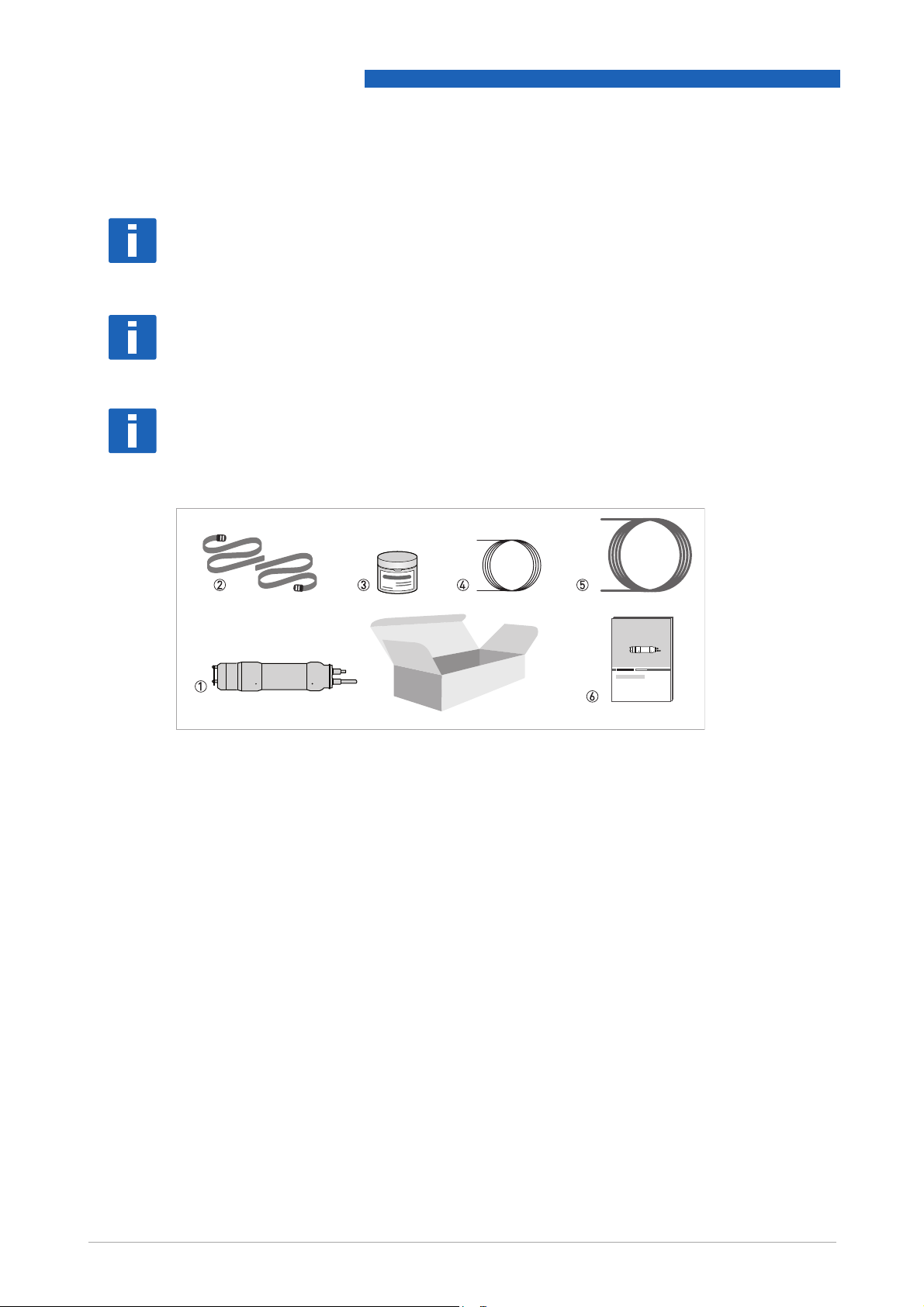
Figure 2-1: Standard scope of delivery
1 AAS 2000 dissolved oxygen sensor
2 2 pcs of straps
3 Electrode cartridge AAS 2000 DO
4 10 m / 33 ft signal cable
5 10 m / 33 ft flush hose
6 Handbook
Optional accessories
• Protection plate AAS 2000 membrane
• MAA 2000 insertion holder, telescopic rod for OAS/AAS 2000 (incl. telescopic rod plus rod
holder, handrail mounting bracket and sensor adapter)
• MAA 2000 side wall mounting for OAS/AAS 2000
• Signal cable extension for OPTISENS 2000 sensors, 10 m / 33 ft
• Signal cable extension for OPTISENS 2000 sensors, 30 m / 98 ft
Consumables/Spare parts available
• Electrode cartrige AAS 2000 DO
8
www.krohne.com 12/2008 • MA AAS 2000 R01 en
Page 9

OPTISENS AAS 2000
2.2 Device description
The sensor is designed to continuously measure dissolved oxygen levels in liquids. It is effective
in saving energy costs associated with aeration systems in an activated sludge process. In
addition, accurate measuring of dissolved oxygen allows for better control of
nitrification/denitrification.
This manual details installation procedures and operational features of the sensor. Menu
navigation and technical data for the MAC 080 converter can be found in the MAC 080 manual.
2.2.1 Design
The sensor is manufactured with 316SS (SS2343) stainless steel. Built-in flushing nozzles allow
for the most accurate readings with little maintenance. The electronics is protected in the
rugged casing, ensuring its reliability in very demanding environments.
DEVICE DESCRIPTION 2
The sensor has a fixed, shielded 10 m / 33 ft cable used for signal transmission between the
sensor and the MAC 080 converter. The cable sheath is made of Hytrel and is highly resistant to
aggressive materials and fluids.
www.krohne.com12/2008 • MA AAS 2000 R01 en
9
Page 10
2 DEVICE DESCRIPTION
2.3 Nameplates
INFORMATION!
Look at the device nameplate to ensure that the device is delivered according to your order.
Check for the correct supply voltage printed on the nameplate.
2.3.1 OPTISENS AAS 2000
OPTISENS AAS 2000
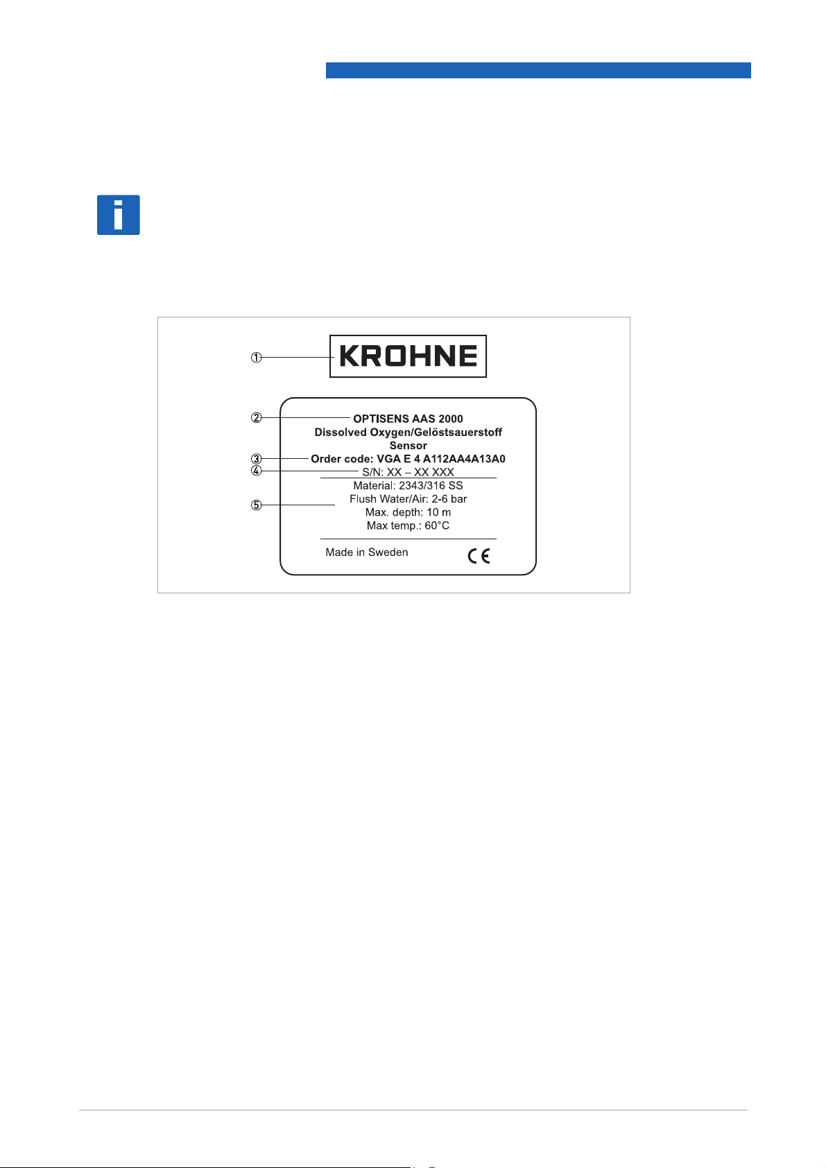
Figure 2-2: Nameplate
1 Manufacturer
2 Device type
3 Order code
4 Serial number
5 Sensor information
10
www.krohne.com 12/2008 • MA AAS 2000 R01 en
Page 11

OPTISENS AAS 2000
3.1 Notes on installation
INFORMATION!
Inspect the cartons carefully for damage or signs of rough handling. Report damage to the
carrier and to the local office of the manufacturer.
INFORMATION!
Check the packing list to check if you received completely all that you ordered.
INFORMATION!
Look at the device nameplate to ensure that the device is delivered according to your order.
Check for the correct supply voltage printed on the nameplate.
3.2 Storage & Transport
INSTALLATION 3
• Store the device in a dry, dust-free location.
• Avoid continuous direct sunlight.
• The original packaging is designed to protect the equipment. It has to be used if you the
device is transported or send back to the manufacturer.
www.krohne.com12/2008 • MA AAS 2000 R01 en
11
Page 12
3 INSTALLATION
3.3 Installing or changing the electrode
INFORMATION!
The sensor is delivered with the electrode uninstalled. The electrode must be installed and
calibrated before the sensor is submerged into water.
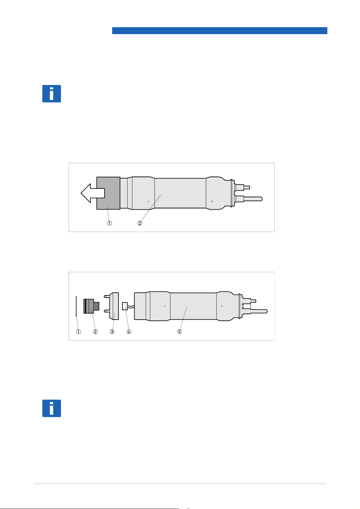
A plastic cap protects the electrode connection plug and the flushing nozzle in the sensor.
Remove the plastic cap before installing the electrode. Retain the plastic cap as it may be used
as protection later. Do not press on the top of the cap if the electrode is installed.
OPTISENS AAS 2000
Figure 3-1: Removal of plastic cap
1 Plastic cap
2 Sensor
Figure 3-2: Overview of the sensor
1 Protection plate
2 Electrode
3 Flushing head
4 Cable connector
5 Sensor housing
INFORMATION!
The electrode can usually be assembled and disassembled without tools.
12
www.krohne.com 12/2008 • MA AAS 2000 R01 en
Page 13

OPTISENS AAS 2000
CAUTION!
Do not ever clamp onto the sensor housing or part of the cable when installing or removing the
flushing head.
Do not touch the membrane of the electrode when mounting.
INSTALLATION 3
Figure 3-3: Installing a new electrode
Installing a new electrode (see figure above)
• Untighten the flushing head about one turn counterclockwise (if not already loose) to let the
air out when the electrode is pushed in place 1.
• Take the electrode out of the plastic container.
• Plug the electrode cable of the sensor into the connector on the electrode 2.
• Install the new electrode into the flushing head 3.
• Tighten the flushing head.
• Mount the protection plate, if needed 4. See below for instructions on mounting the
protection plate.
• Perform a a new air-calibration. An air calibration must be performed whenever the electrode
is changed.
i Installation of the electrode is completed.
www.krohne.com12/2008 • MA AAS 2000 R01 en
13
Page 14
3 INSTALLATION
OPTISENS AAS 2000
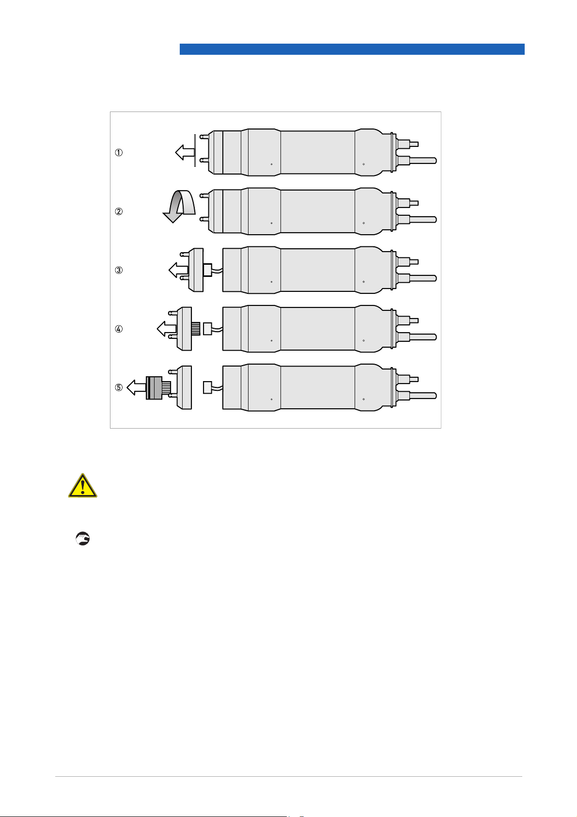
Figure 3-4: Removing an old electrode
CAUTION!
Make sure the electrode housing is dry before removing the flushing head. Water may come in to
the housing when the flushing head is removed.
Removing an old electrode (see figure above)
• Make sure automatic flushing is disabled. This can be checked at the MAC 080 converter in the
Cleaning
Cleaning menu of the AAS 2000 sensor ( on page 22).
CleaningCleaning
• If using the protection plate, pull it off before changing the electrode 1.
• Loosen the flushing head by turning it counterclockwise 2.
• Gently pull the flushing head out of the sensor housing 3
• Unplug the electrode 4.
• Remove the electrode from the flushing head by pressing firmly on the backside of the
electrode near the cable connector 5.
• Ensure that the O-ring that seals the flushing head is completely seated in the respective
groove in the sensor body.
• If a new electrode is to be mounted, please follow the previous instructions ("Installing a new
electrode").
14
www.krohne.com 12/2008 • MA AAS 2000 R01 en
Page 15

OPTISENS AAS 2000
• Screw the flushing head back onto the sensor. Do not screw it tight, otherwise the mounting of
a new electrode (see previous instructions) will become more complicated.
• If a new electrode is not to be mounted, place the plastic cap over the electrode connection
plug and the flushing nozzle in the sensor.
CAUTION!
Do not ever remove a flushing nozzle in order to mount the protection plate. The nozzles are
fastened with a special locking jam.
Mounting the protection plate
• Remove the o-rings in the groove at the top of the three nozzles.
• Bend the plate slightly and press it down between the flushing nozzles.
• Ensure that the plate fits into the notches on the flushing nozzles. Correct the plate when it is
mounted.
INSTALLATION 3
3.4 Mounting of the sensor
The sensor can be mounted in two ways:
• On a telescopic fiberglass rod placed in a mounting bracket that fastens to a handrail ( on
page 15).
• To an adjustable slide rail holder ( on page 18)
Installation tips
• Adjust the rod so that the sensor is at least 30 cm/11.8" below the liquid surface or the lowest
water level in decant applications to prevent the sensor from coming out of the liquid.
• In an aeration tank, ensure that the sensor is not directly above a diffuser head. It should be
installed on the backside of the rolling diffuser effect.
• Flushing may not be required if the tank is well agitated. To verify the need for flushing,
remove the sensor from the liquid after it has been in the liquid for several days.
3.4.1 Mounting to MAA 2000 telescopic rod immersion holder
The mounting bracket of the telescopic rod is mounted to a handrail or a separate holder.
In case a handrail is not available, a mounting post with a vertical bar for sensor mounting can be
purchased from the manufacturer.
www.krohne.com12/2008 • MA AAS 2000 R01 en
15
Page 16

3 INSTALLATION
OPTISENS AAS 2000
Figure 3-5:
1 Telescopic rod
2 Rod holder
Figure 3-6: Pulling the cable/hose through the rod
1 Cable/hose
2 Telescopic rod
3 Sensor holder
4 Sensor
Placing the rod holder around the rod
16
Figure 3-7: Inserting the rod holder into the mounting bracket
1 Telescopic rod
2 Rod holder
3 Mounting bracket
www.krohne.com 12/2008 • MA AAS 2000 R01 en
Page 17

OPTISENS AAS 2000
INSTALLATION 3
1 Telescopic rod
2 Sensor holder
3 Handrail with mounting bracket attached
4 Rod holder
5 Mounting bracket
CAUTION!
Do not extend the rod sections beyond the black lines. This could lead to rod damage.
INFORMATION!
For best measurement, the rod shall be mounted in an angle, 5...30
°
from vertical.
Mounting to telescopic rod immersion holder
• Mount the flexible mounting bracket on an existing handrail or on a separate holder, diameter
32...50 mm/1.3...2.0" or square 28...42 mm/1.1...1.7". The bent lip on the mounting plate shall
be on top and faced toward the liquid or tank.
• Adjust the mounting bracket to the correct angle and tighten the nuts.
i The bracket shall be fixed to the rail, and must not be able to rotate around it.
• Disassemble the rod holder and place it around the telescopic rod.
• Use the SS screws on the rod holder to tighten the rod holder to the rod.
• Pull the cable and hose through the sensor holder and rod.
• Connect the sensor to the rod with the two piece black PVC sensor holder.
• Tighten the adapter halves until snug, which will leave about 1.5 mm/0.06" gap.
The gap is required so the water can drain from the rod.
• Adjust the length of the telescopic rod as necessary by twisting the nuts while holding the rod.
Do not extend the rod sections beyond the black lines. This could lead to rod damage.
www.krohne.com12/2008 • MA AAS 2000 R01 en
17
Page 18

3 INSTALLATION
• Insert the PVC rod holder with the telescopic rod into the mounting bracket. Make sure that
the guide tracks of the rod holder are properly seated in the bracket.
• Fasten the safety-locking clamp.
• Check that the mounting bracket is safely fixed to the rail for the spring to work the way it is
intended.
3.4.2 Mounting to MAA 2000 slide rail immersion holder
OPTISENS AAS 2000
18
Figure 3-8: Mounting to MAA 2000 slide rail immersion holder
1 Slide rail immersion holder
2 Sensor
3 66 mm / 2.60" clamp
4 Adjustable stop
CAUTION!
In order to avoid large air bubbles which can affect the measurement please make sure that the
slide rail immersion holder is mounted in a certain angle to the vertical position. The angle
should be slightly off from vertical position (approx. 20
www.krohne.com 12/2008 • MA AAS 2000 R01 en
°
), but not more than 90°.
Page 19

OPTISENS AAS 2000
Mounting to MAA 2000 slide rail immersion holder
• Mount the slide rail immersion holder to the side wall of the basin or open channel using the
two predrilled holes. The adjustable stop should be on the bottom and the two sliding clamps
above.
• Take the two sliding clamps off from the slide rail and mount them around the sensor housing.
Make sure that the clamps are placed on the two elevated ends of the sensor housing (one on
the upper part and one on the lower part, see figure above).
The two guide tracks have to line-up in one straight line to each other.
• Slide the sensor with the two clamps into the slide rail. Make sure that the guide tracks of the
two clamps are properly seated.
• Adjust the sensor position as necessary and fasten the adjustable stop.
3.5 Removing the sensor
CAUTION!
Opening the sensor housing will void all warranty! The sensor housing may not be opened except
by service personnel.
INSTALLATION 3
CAUTION!
Do not use any sharp cleaning utensils (e.g. brush) on the membrane. The membrane should be
cleaned with a soft cloth only!
The sensor housing and the telescopic rod may be cleaned with a soft brush or cloth, but not with
a wire brush or other sharp tools.
Removing the sensor from telescopic rod installation
• Disconnect the sensor cable from the MAC 080 converter and the flushing hose from the
solenoid valve.
• Open the clamp, and pull the rod out of the mounting bracket.
• Make sure all water inside the rod is drained.
• Open the black sensor adapter.
• Clean the sensor housing and rod with a soft brush or cloth. Do not use a wire brush or sharp
tools!
• Flush the inside of the rod with clean water.
• Mount the protective cap (or a small plastic bag) on the sensor cable connector.
• Pull the cable and flushing hose out of the rod.
• Blow compressed air through the flushing hose to get rid of the water in the hose and the
sensor.
• Place the plastic cap over electrode and flushing head to protect the membrane.
www.krohne.com12/2008 • MA AAS 2000 R01 en
19
Page 20

3 INSTALLATION
Removing the sensor from MAA 2000 slide rail assembly
• Disconnect the sensor cable from the MAC 080 converter and the flushing hose from the
solenoid valve.
• Pull the sensor out of the slide rail and detach the two clamps.
• Clean the sensor housing with a soft brush or cloth. Do not use a wire brush or sharp tools!
• Mount the protective cap (or a small plastic bag) on the sensor cable connector.
• Blow compressed air through the flushing hose to get rid of the water in the hose and the
sensor.
• Place the plastic cap over electrode and flushing head to protect the membrane.
OPTISENS AAS 2000
20
www.krohne.com 12/2008 • MA AAS 2000 R01 en
Page 21

OPTISENS AAS 2000
4.1 Safety instructions
DANGER!
All work on the electrical connections may only be carried out with the power disconnected. Take
note of the voltage data on the nameplate!
DANGER!
Observe the national regulations for electrical installations!
WARNING!
Observe without fail the local occupational health and safety regulations. Any work done on the
electrical components of the measuring device may only be carried out by properly trained
specialists.
ELECTRICAL CONNECTIONS 4
INFORMATION!
Look at the device nameplate to ensure that the device is delivered according to your order.
Check for the correct supply voltage printed on the nameplate.
4.2 Cable connections
INFORMATION!
Please refer to the MAC 080 manual for detailed information.
Connect the sensor to the MAC 080 converter using the connector on the end of the attached
sensor cable. In the event that two sensors are to be connected to the same converter, use the
optional junction box.
www.krohne.com12/2008 • MA AAS 2000 R01 en
21
Page 22

5 OPERATION
5.1 Sensor display
By simultaneously pressing ↓ and ^ you alter between the converter main menu and the
sensor information display for the selected sensor.
The sensor has two information displays. The first one, in addition to the measured value, shows
the current temperature of the electrode, the setvalue for air and the "slope" of the electrode at
the last air calibration. The second information display shows the date of the last calibration and
the date the electrode was changed.
5.2 Menu
Use ↑ or ↓ to select the sensor in the main display. The menu for the selected sensor is accessed
by pressing ^ for five seconds. If the selected sensor is not active (the text No transmitter
shown) a warning is displayed that asks you to make another choice in order to show the sensor
menu.
OPTISENS AAS 2000
No transmitter is
No transmitterNo transmitter
Menu "Settings"
Submenu Description
Tag
Tag Name of the sensor shown in the main display (10 characters).
TagTag
I-Time
I-Time Integration time or dampening – can be set up to 999 seconds.
I-TimeI-Time
Decimals
Decimals 1 or 2 for display and menu.
DecimalsDecimals
Analog
Analog "None" , "Out1", "Out2", "Out3", "Out4", "Out1+2" or "Out3+4". Pick
AnalogAnalog
Second
Second "Temp" or "=Prim". If two analog outputs are chosen above, the first
SecondSecond
Temp 0-
Temp 0- Temperature scaling, value that will give max output on second
Temp 0-Temp 0-
which analog output(s) are to be used with sensor
will always give the primary value according to the sensors selected
scale. The second will either give the temperature scaled as stated
below, or the same signal as the first channel. The temperature is
additional information, not a precision measurement.
channel.
22
www.krohne.com 12/2008 • MA AAS 2000 R01 en
Page 23

OPTISENS AAS 2000
Menu "Calibrate"
Submenu Description
Airpres.mB
Airpres.mB Specify within 10 mBar.
Airpres.mBAirpres.mB
Calibrate
Calibrate "No", "Zero" or "Air". Select what calibration to do.
CalibrateCalibrate
Temp(info)
Temp(info) Shows actual temperature in the electrode.
Temp(info)Temp(info)
Test(info)
Test(info) Shows actual dissolved oxygen level.
Test(info)Test(info)
Setvalue
Setvalue Theoretical reading in air at current temperature and with the air
SetvalueSetvalue
Slope
Slope Slope of the electrode at last air calibration.
SlopeSlope
Calibrated
Calibrated Date of last air calibration.
CalibratedCalibrated
New electr.
New electr. Date when electrode was last changed. Push ^ to edit the date, then
New electr.New electr.
OPERATION 5
pressure entered above. Shall be the same as Test
the calibration.
This value is an indication of the wearing of the electrode and it is
normally over 80 for a well functioning electrode. However, an
electrode may also function well at lower values. At values below 50 it
is recommended to replace the electrode.
^ again to store it.
Test immediately after
TestTest
Menu "Cleaning"
Submenu Description
Press ^ to go to the cleaning program
Cleaner
Cleaner "None", "Flush", or "Brush". Do not select "Brush" since this does
CleanerCleaner
Interval min
Interval min 0...999 minutes, time between cleaning cycles (only for master)
Interval minInterval min
Length sec
Length sec 0...999 seconds, duration of flushing cycle (only for master)
Length secLength sec
Freeze sec
Freeze sec 0...999 seconds, extra freeze time of output signal after a
Freeze secFreeze sec
Relay
Relay "-", "1", "2", "Along 1", or "Along 2". Select relay to operate solenoid
RelayRelay
Next time
Next time The next scheduled cleaning time. Pushing ^ on this line will set the
Next timeNext time
not exist for this sensor (only for master).
flushing cycle
for flush cycle if this sensor is a master with its own relay, or relay
used by master if this sensor is a slave.
These are the same relays used for Alarm relay
time to current time and start a cleaning cycle. This could be used to
test the "Flush" cycle (only for master).
Alarm relay below.
Alarm relayAlarm relay
Menu "Scale / Alarm"
Submenu Description
Max
Max 0...99.9 mg/l, equal to 20 mA output signal.
MaxMax
Min
Min 0...99.9 mg/l, equal to 4 mA output signal.
MinMin
Hi-Alarm
Hi-Alarm 0...99.9 mg/l, the value zero inactivates the alarm.
Hi-AlarmHi-Alarm
Low-Alarm
Low-Alarm 0...99.9 mg/l, the value zero inactivates the alarm.
Low-AlarmLow-Alarm
Alarm Relay
Alarm Relay "-" "1", "2", or "1 and 2". Check that the relay is not being used for
Alarm RelayAlarm Relay
cleaning.
www.krohne.com12/2008 • MA AAS 2000 R01 en
23
Page 24

5 OPERATION
Menu "System"
Submenu Description
Type
Type Type of sensor, read only
TypeType
Serial
Serial Serial number of the sensor, read only
Serial Serial
SoftW
SoftW Software version of the sensor, read only
SoftWSoftW
Temp
Temp Sensor temperature, read only
TempTemp
MaxTemp
MaxTemp The highest temperature the sensor has been exposed to, read only
MaxTempMaxTemp
Info
Info Press ^ to go to Info
InfoInfo
MS0 SA value for zero sample.
MS1 SA value for air sample.
Cons 1 Calculated concentration at last air calibration.
Ch1 Raw value for dissolved oxygen measurement.
Ch2 Raw value for channel temperature measurement.
Con mg/l. This is what is displayed on main screen.
Samp/s Number of samples per second.
Service
Service Not accessible for users.
ServiceService
Info read only menu.
InfoInfo
OPTISENS AAS 2000
24
www.krohne.com 12/2008 • MA AAS 2000 R01 en
Page 25

OPTISENS AAS 2000
5.3 Calibration
Leave the instrument turned on for about 30 minutes prior to calibration so that the sensor and
electronics can stabilize.
5.3.1 Zero calibration
The sensor is zero calibrated at the factory and does not often need to be zero calibrated. We do
however recommend to do a new zero calibration when replacing the electrode since half the job
is then already done.
Running a zero calibration
• Remove the electrode before performing a zero calibration ( on page 12).
• Select the sensor to be calibrated in the menu by using ↑ or ↓.
• Press ^ for approximately 5 seconds to enter the sensor menu.
• Select Calibrate
• Select Zero
• Wait for the zero calibration to finish (usually takes about 20 seconds).
i A dialog box saying "Calibration done" will come up after successful calibration
• Press ^ to return to the previous menu.
i The sensor is zero calibrated.
• Continue with air calibration ( on page 25).
Calibrate and then press ^.
CalibrateCalibrate
Zero by using ↑ or ↓ and then press ^.
ZeroZero
OPERATION 5
INFORMATION!
Detailed procedures for navigating the converter software can be found in the MAC 080 manual.
5.3.2 Air calibration
Please observe the following points while performing an air calibration:
• It is important to create a constant environment.
• The electrode cartridge must be dry with no water drops on the membrane.
• If rain and/or strong winds are present, the calibration procedure could be disturbed. In this
case shield the equipment so that it is protected from the rain or wind.
• An open plastic bag over the sensor may slow the calibration time down, but is otherwise a
good way to create constant conditions.
www.krohne.com12/2008 • MA AAS 2000 R01 en
25
Page 26

5 OPERATION
Performing an air calibration
• Fill a bucket halfway with water.
• Place the sensor about 30...45 cm/1...1.5 ft above the water surface to create a humid
environment.
• Cover the bucket with a towel.
• Select the sensor to be calibrated in the menu by using ↑ or ↓.
• Press ^ for approximately five seconds to enter the sensor menu.
• Select Calibrate > Airpres.mB
• Enter the current air pressure in mbar using ↑ or ↓ to change a digit and ^ to move on to the
• Select Calibrate > Calibrate
• Select Air
• Press ^.
• Wait for the sensor to be calibrated. A successful calibration will take anywhere between 5...15
i A dialog box saying "Calibration done" will come up after successful calibration.
• Press ^ to return to the previous menu.
• Select Calibrate > Calibrated
• Enter the date of the air calibration using ↑ or ↓ to change a digit and ^ to move on to the next
• Press ^ to return to the previous menu.
i The sensor is air calibrated.
Calibrate > Airpres.mB and press ^.
Calibrate > Airpres.mBCalibrate > Airpres.mB
next digit. It is sufficient to specify the pressure within 10 mbar (see table below for
conversion from inHg to mbar).
Calibrate > Calibrate and press Press ^.
Calibrate > CalibrateCalibrate > Calibrate
Air using ↑ or ↓ (three choices can be made, "Air"/"No"/"Zero").
AirAir
minutes for the sensor to stabilize.
Calibrate > Calibrated and press Press ^.
Calibrate > CalibratedCalibrate > Calibrated
digit.
OPTISENS AAS 2000
The following appear in the calibration menu as read-only:
• Temp (info)
Temp (info): Displays the current temperature of the sensor.
Temp (info)Temp (info)
• Test (info)
Test (info): Displays the current measured dissolved oxygen value. Immediately after
Test (info)Test (info)
calibration and before the sensor is placed in the liquid, this value should closely resemble
Setvalue. A reading outside of an acceptable range may indicate that the electrode needs to
be replaced.
• Setvalue
Setvalue: Ideal value calculated using temperature and air pressure.
SetvalueSetvalue
26
www.krohne.com 12/2008 • MA AAS 2000 R01 en
Page 27

OPTISENS AAS 2000
Air pressure conversion
It is important to enter the correct air pressure before doing an air calibration. Air pressure is
measured in mbar (which is exactly the same as the SI-unit hPa).Below is a formula and a table
to convert from inHG to mbar (and thus to hPa):
mbar = (inHg * 1000) ÷ 29.5
inHg
inHg mbar
inHginHg
29.2 990
29.3 993
29.4 997
29.5 1000
29.6 1003
29.7 1007
29.8 1010
29.9 1014
30.0 1017
30.1 1020
30.2 1024
30.3 1027
30.4 1030
mbar
mbarmbar
OPERATION 5
5.4 Scaling
The Scale / Alarm
low boundaries for a 4...20 mA output signal. In addition, this menu allows the user to set high
and low alarm values to switch a relay when solids have reached critical points.
Max
Max sets the 20 mA point output
MaxMax
Min
Min sets the 4 mA point output (may be negative for special applications)
MinMin
Hi-Alarm
Hi-Alarm sets the high alarm set point; the value zero inactivates the alarm
Hi-AlarmHi-Alarm
Low-Alarm
Low-Alarm sets the low alarm set point; the value zero inactivates the alarm
Low-AlarmLow-Alarm
Scale / Alarm menu (see the OPTISENS MAC 080 manual) allows the user to set the high and
Scale / AlarmScale / Alarm
www.krohne.com12/2008 • MA AAS 2000 R01 en
27
Page 28

6 SERVICE
6.1 Cleaning
6.1.1 Cleaning the sensor
The sensor is equipped with built-in flushing nozzles. The nozzles are used to direct the cleaning
medium (compressed air or water) via a flushing hose that is connected to the top of the sensor
housing. A solenoid valve that is wired to a relay in the converter controls the air or liquid (see
handbook OPTISENS MAC 080).
Compressed air is recommended for most applications.
Please observe the following:
• Flush as little as possible. Flushing wears the membrane of the electrode. Excessive flushing
reduces the lifetime of the electrode.
• Try flushing shortly twice per day (720 minutes interval, 5 seconds length). If this doesn’t keep
the membrane clean, first reduce the interval, then increase the length.
OPTISENS AAS 2000
CAUTION!
Never flush if the electrode is not installed!
When the electrode is not installed, the plastic cap should be kept on the end of the sensor for
protection.
CAUTION!
The highest allowed flushing pressure is 6 bar / 87 psi. When using air, 2 bar / 29 psi is usually
sufficient.
INFORMATION!
Pay attention to the requirements for protection against backflow, according to the
EN 1717 standard for drinking water devices. If possible, use plant reuse water or effluent water
for cleaning.
28
Figure 6-1: Flushing system
1 Flushing
2 Flushung tube
3 Sensor cable
INFORMATION!
In order to clean the sensor, flushing must be activated in the Settings
Settings menu in the MAC 080
SettingsSettings
converter
www.krohne.com 12/2008 • MA AAS 2000 R01 en
Page 29

OPTISENS AAS 2000
There are two different ways of cleaning a sensor: The sensor can either be cleaned as a master
or as a slave. Both options are described in the following instructions.
Cleaning the sensor as a master (sensor has its own relay)
• Select the sensor in the main menu by using ↑ or ↓.
• Press ^ for approximately five seconds to enter the sensor menu.
• Use ↑ or ↓ to select Cleaning
• In the Cleaning
• Then specify the cleaning interval in minutes (Interval min
(Lenght sec
Lenght sec).
Lenght secLenght sec
• Specify the relay to be used according to the wiring inside the MAC 080 converter. For
example, if the solenoid is wired to relay #1, set Relay
• For sensors configured as masters, Next time
Pushing ^ will set it to current time and thus start cleaning.
• If needed, specify the extra freeze time in seconds (Freeze sec
Cleaning and press ^.
CleaningCleaning
Cleaning submenu, select Cleaner
CleaningCleaning
Cleaner and set it to Flush
CleanerCleaner
Next time displays the next time flush will be activated.
Next timeNext time
SERVICE 6
Flush.
FlushFlush
Interval min) and the flush time in seconds
Interval minInterval min
Relay to #1
RelayRelay
#1 for flushing.
#1#1
Freeze sec).
Freeze secFreeze sec
Cleaning the sensor as a slave (along with another sensor)
• Select the sensor in the main menu by using ↑ or ↓.
• Press ^ for approximately five seconds to enter the sensor menu.
• Use ↑ or ↓ to select Cleaning
• The parameters Cleaner
the sensor being the master.
• Set Relay
Relay to Along #1
RelayRelay
• If needed, specify the extra freeze time in seconds (Freeze sec
Along #1 or Along #2
Along #1Along #1
Cleaning and press ^.
CleaningCleaning
Cleaner, Interval min
CleanerCleaner
6.1.2 Cleaning the flushing nozzle
If the flushing nozzle becomes plugged, it can usually be cleaned by backflushing it with clean
water.
Cleaning the flushing nozzle
• Before attempting to backflush, close the valve for the flush water source.
• Disconnect the sensor flushing hose from the solenoid valve.
• Place a 12 mm / 0.47" hose over the flush nozzle and carefully open the water valve.
i The pressure should clear the line of solids. If backflushing does not work initially, try
cleaning the three flushing nozzles with a needle. Try backflushing the nozzles again as
described above until clean water comes out at the solenoid valve end of the hose.
Interval min and Lenght sec
Interval minInterval min
Along #2 depending on what relay the master sensor uses.
Along #2Along #2
Lenght sec in the Cleaning
Lenght secLenght sec
Freeze sec).
Freeze secFreeze sec
Cleaning submenu are set for
CleaningCleaning
www.krohne.com12/2008 • MA AAS 2000 R01 en
29
Page 30

6 SERVICE
6.2 Spare parts availability
The manufacturer adheres to the basic principle that operational spare parts for each device or
each important accessory part will be kept available for a period of 10 (ten) years after delivery of
the last production run for that device.
Operational spare parts are defined as parts that are subject to faults in normal operation.
6.3 Availability of services
The manufacturer offers a range of services to support the customer after expiration of the
warranty. These include repair, technical support and training.
INFORMATION!
For more precise information, please contact your local representative.
OPTISENS AAS 2000
30
www.krohne.com 12/2008 • MA AAS 2000 R01 en
Page 31

OPTISENS AAS 2000
6.4 Support information form
Before calling the customer support, please collect the information in this form and have it at
hand.
Company:
Company: Name:
Company:Company:
Phone:
Phone: E-mail:
Phone:Phone:
Sensor type:
Sensor type: Position / tag:
Sensor type:Sensor type:
Name:
Name:Name:
E-mail:
E-mail:E-mail:
Position / tag:
Position / tag:Position / tag:
SERVICE 6
First go to the converter menu by pressing ↑ and ^ simultaneously for five seconds. Then select System
and press ^. Write down the following information.
Version:
Version:
Version:Version:
Serial:
Serial:
Serial:Serial:
Box temp:
Box temp:
Box temp:Box temp:
Box heat:
Box heat:
Box heat:Box heat:
Leave the converter menu by pressing ↑ and ^ simultaneously. Use ↑ and ↓ to select the sensor in the
main display. Go to the sensor menu by pressing ^ for five seconds. Then select System
Write down the following information.
Type:
Type: SoftW:
Type:Type:
Serial:
Serial: Temp:
Serial:Serial:
Select System > Info
System > Info and press ^. Write down the following information.
System > InfoSystem > Info
MS0:
MS0: MS1:
MS0:MS0:
Cons 1:
Cons 1: Ch1:
Cons 1:Cons 1:
Ch2:
Ch2: Con:
Ch2:Ch2:
Samp/s:
Samp/s:
Samp/s:Samp/s:
Leave the menu by pressing ↑ and ^ simultaneously.
SoftW:
SoftW:SoftW:
Temp:
Temp:Temp:
MS1:
MS1:MS1:
Ch1:
Ch1:Ch1:
Con:
Con:Con:
System and press ^.
SystemSystem
System
SystemSystem
www.krohne.com12/2008 • MA AAS 2000 R01 en
31
Page 32

6 SERVICE
6.5 Returning the device to the manufacturer
6.5.1 KROHNE representative
INFORMATION!
Please contact your local KROHNE representative prior to returning this device!
6.5.2 General information
This device has been carefully manufactured and tested. If installed and operated in accordance
with these operating instructions, it will rarely present any problems.
CAUTION!
Should you nevertheless need to return a device for inspection or repair, please pay strict
attention to the following points:
•
Due to statutory regulations on environmental protection and safeguarding the health and
safety of our personnel, manufacturer may only handle, test and repair returned devices that
have been in contact with products without risk to personnel and environment.
•
This means that the manufacturer can only service this device if it is accompanied by the
following certificate (see next section) confirming that the device is safe to handle.
OPTISENS AAS 2000
CAUTION!
If the device has been operated with toxic, caustic, flammable or water-endangering products,
you are kindly requested:
•
to check and ensure, if necessary by rinsing or neutralizing, that all cavities are free from
such dangerous substances,
•
to enclose a certificate with the device confirming that is safe to handle and stating the
product used.
32
www.krohne.com 12/2008 • MA AAS 2000 R01 en
Page 33

OPTISENS AAS 2000
6.5.3 Form (for copying) to accompany a returned device
Company: Address:
Department: Name:
Tel. no.: Fax no.:
Manufacturer's order no. or serial no.:
The device has been operated with the following medium:
SERVICE 6
This medium is: water-hazardous
toxic
caustic
flammable
We checked that all cavities in the device are free from such
substances.
We have flushed out and neutralized all cavities in the
device.
We hereby confirm that there is no risk to persons or the environment through any residual media
contained in the device when it is returned.
Date: Signature:
Stamp:
6.6 Disposal
CAUTION!
Disposal must be carried out in accordance with legislation applicable in your country.
www.krohne.com12/2008 • MA AAS 2000 R01 en
33
Page 34

7 TECHNICAL DATA
7.1 Measuring principle
The electrode is a Clark type electrode with a membrane in FEP. The sensor consists of a gold
cathode and silver anode. The Clark cell detects the oxygen though its reduction at the gold
electrode. A membrane covers the two electrodes and blocks access of most species to the
electrodes. Only dissolved gases such as oxygen can traverse the membrane, hence the
reduction current responds to the oxygen concentration.
The electrode housing is made of PVC and is equipped with an O-ring sealing against the
mounting. There is a connector on the electrode for the amplifier cable.
Active components included in the electrode are treated to maximize their life span.
In addition, the temperature is measured to be used for temperature compensation of the
measured value. It can be read in the converter and used as secondary value when a sensor is
configured to use both analog outputs.
INFORMATION!
The build in temperature measurement is not a precision measurement, but shall be seen as an
indication.
OPTISENS AAS 2000
7.2 Technical data
Measuring system
Measuring principle Amperometric measuring principle with a
Application range Continuous measurement of dissolved oxygen
Modular design A typical measuring system consists of:
Measuring range 0…20 mg/l (ppm)
Measuring accuracy ±1% FS (full scale)
Operating conditions
Temperature range 0…+50°C / 32…122°F
Max. immersion depth 10 m / 32.8 ft
Calibration Software-support zero point calibration and
"Clark" electrode
in water (here especially in waste water
applications), e.g. in aeration basins
MAC 080 multiparameter converter
1 (or up to 4) OPTISENS 2000 sensors
Solenoid valves to control spray cleaning
Assemblies for submersion or side wall
installation
single point calibration by calibration
measurement in air
34
www.krohne.com 12/2008 • MA AAS 2000 R01 en
Page 35

OPTISENS AAS 2000
Installation conditions
AAS 2000 + MAA 2000 fibreglass telescopic rod for
submersible installations
AAS 2000 + MAA 2000 slide rail mounting for side wall
installations
Automatic spray cleaning Flushing using clean water or compressed air;
Process connection Submersible version in open basins and
TECHNICAL DATA 7
Installation on the handrail with up to 4 m
length-adjustable, oscillating fibreglass
assembly
Handrail mounting for:
- Round handrails: d = 32...50 mm / 1.3…2"
- Square cross-sections: 28...42 mm / 1.1…1.7"
Installation on side walls of channels and
basins using slide rails for simple sensor
removal.
Pressure: 2...6 bar / 29…87 psi
Solenoid valve: available in 220 V and 117 V
versions; up to max. 2 sensors can be operated
on a single valve
Flush hose: ¼" external diameter; PE; standard
length: 10 m / 32.8 ft
channels
Materials
Enclosure SIS2343 (316 SS)
“Clark” electrode Design: replacable cartridge
Cathode: gold
Anode: silver
Membrane: FEP Teflon (0.025 mm / 0.001")
Connection cable to converter Insulation: Hytrel; 5-pin M 12 connector; fixed
Flush hose PE
cable, shielded, 10 m / 32.8 ft long
www.krohne.com12/2008 • MA AAS 2000 R01 en
35
Page 36

7 TECHNICAL DATA
Approvals
Protection class IP68 (Nema 6)
Approval symbol CE
EMC (89/336/EEC) Interference emission to EN 61000-6-4:2001;
Low voltage directive (89/336/EEC) Safety requirements for electrical equipment
7.3 Dimensions and weight
OPTISENS AAS 2000
immunity to EN 61000-6-2:2001
for measurement, control, and laboratory use
in accordance with EN 61010-1:2001
36
Dimensions
[mm]
a 61 2.4 2.1 4.6
b 66 2.6
c 275 10.5
d 307 12.1
www.krohne.com 12/2008 • MA AAS 2000 R01 en
Dimensions
[inches]
Weight
[kg] [lbs]
Page 37

OPTISENS AAS 2000
8.1 Setup information form
This form can be used to document the setup of the sensor.
Sensor type
Sensor type
Sensor typeSensor type
Position / Tag
Position / Tag
Position / TagPosition / Tag
In the System
System submenu of the sensor menu the following information can be collected:
SystemSystem
Serial
Serial
SerialSerial
SoftW
SoftW
SoftWSoftW
In the Settings
Settings submenu of the sensor menu the following parameters can be set:
SettingsSettings
I-time
I-time
I-timeI-time
APPENDIX 8
Decimals
Decimals
DecimalsDecimals
Analog
Analog
AnalogAnalog
Second
Second
SecondSecond
In the Cleaning
Cleaning submenu of the sensor menu the following parameters can be set:
CleaningCleaning
Cleaner
Cleaner
CleanerCleaner
Cleaning interval
Cleaning interval
Cleaning intervalCleaning interval
Cleaning length
Cleaning length
Cleaning lengthCleaning length
Cleaning freeze
Cleaning freeze
Cleaning freezeCleaning freeze
Cleaning relay
Cleaning relay
Cleaning relayCleaning relay
In the Scale / Alarm
Scale / Alarm submenu of the sensor menu the following parameters can be set:
Scale / AlarmScale / Alarm
Max
Max
MaxMax
Min
Min
MinMin
High alarm
High alarm
High alarmHigh alarm
Low alarm
Low alarm
Low alarmLow alarm
Alarm relay
Alarm relay
Alarm relayAlarm relay
Leave the menu by pressing ↑ and ^ simultaneously.
www.krohne.com12/2008 • MA AAS 2000 R01 en
37
Page 38

8 APPENDIX
OPTISENS AAS 2000
38
www.krohne.com 12/2008 • MA AAS 2000 R01 en
Page 39

OPTISENS AAS 2000
APPENDIX 8
www.krohne.com12/2008 • MA AAS 2000 R01 en
39
Page 40

OPTISENS AAS 2000 nnnnnnnnnnnnnnnnnnnnnnnnnnnnnnnnnnnnnnnnnnnnnnnnnnnn
n
KROHNE measuring technology - Product overview
• Electromagnetic flowmeters • Level measuring instruments
• Variable area flowmeters • Temperature measuring instruments
• Mass flowmeters • Pressure measuring instruments
• Ultrasonic flowmeters • Analysis
• Vortex flowmeters • Oil and gas industry
• Flow controllers
Addresses:
Great Britain
Germany
Northern sales office
KROHNE Messtechnik GmbH & Co. KG
Bremer Str. 133
D-21073 Hamburg
Phone:+49 (0)40 767 3340
Fax:+49 (0)40 767 33412
nord@krohne.com
ZIP code: 10000 - 29999, 49000 - 49999
Western and middle sales office
KROHNE Messtechnik GmbH & Co. KG
Ludwig-Krohne-Straße
D-47058 Duisburg
Phone:+49 (0)203 301 4416
Fax:+49 (0)203 301 10416
west@krohne.com
ZIP code: 30000 - 34999, 37000 48000, 50000 - 53999, 57000 - 59999,
98000 - 99999
Southern sales office
KROHNE Messtechnik GmbH & Co. KG
Landsberger Str. 392
D-81241 Munich
Phone:+49 (0)89 121 5620
Fax:+49 (0)89 129 6190
sued@krohne.com
ZIP code: 0 - 9999, 80000 - 89999,
90000 - 97999
Southwestern sales office
KROHNE Messtechnik GmbH & Co. KG
Rüdesheimer Str. 40
D-65239 Hochheim/Main
Phone: +49(0)6146) 827 30
Fax:+49 (0)6146 827 312
rhein-main@krohne.com
ZIP code: 35000 - 36999, 54000 56999, 60000 - 79999
Instrumentation and control
equipment catalog
TABLAR Messtechnik GmbH
Ludwig-Krohne-Str. 5
D-47058 Duisburg
Phone:+49 (0)2 03 305 88 0
Fax:+49 (0)2 03 305 8888
kontakt@tablar.de; www.tab lar.de
KROHNE sales
companies
International
Australia
Australia
AustraliaAustralia
KROHNE Australia Pty Ltd
Quantum Business Park 10/287
Victoria Rd Rydalmere NSW 2116
Phone: +61 2 8846 1700
Fax: +61 2 8846 1755
krohne@krohne.com.au
Austria
Austria
AustriaAustria
KROHNE Gesellschaft m.b.H.
Modecenterstraße 14
A-1030 Vienna
Phone:+43 (0)1/203 45 32
Fax:+43 (0)1/203 45 32 99
info@krohne.at
Belgium
Belgium
Belgium Belgium
KROHNE Belgium N.V.
Brusselstraat 320
B-1702 Groot Bijgaarden
Phone:+32 (0)2 4 66 00 10
Fax:+32 (0)2 4 66 08 00
krohne@krohne.be
Brazil
Brazil
Brazil Brazil
KROHNE Conaut Controles
Automaticos Ltda.
Estrada Das Águas Espraiadas, 230
C.P. 56 06835 - 080 EMBU - SP
Phone:+55 (0)11-4785-2700
Fax:+55 (0)11 4785-2768
conaut@conaut.com.br
China
China
ChinaChina
KROHNE Measurement Instruments
(Shanghai) Co. Ltd., (KMIC)
9th Floor, Puyuan Science Park,
Building A
396 Guilin Road
Shanghai 200233
Tel.: +86 (021) 6470 5656
Fax: +86 (021) 6451 6408
info@krohne-asia.com
Czech Republic
Czech Republic
Czech RepublicCzech Republic
Krohne CZ, spol. s r.o.
Sobìsická 156
63800 Brno
Phone: +420 (0)545.242 627
Fax: +420 (0)545 220 093
brno@krohne.cz
France
France
FranceFrance
KROHNE S.A.S.
Les Ors BP 98
F-26103 ROMANS Cedex
Phone:+33 (0)4 75 05 44 00
Fax:+33 (0)4 75 05 00 48
info@krohne.fr
Great Britain
Great BritainGreat Britain
KROHNE Ltd.
Rutherford Drive
Park Farm Industrial Estate
Wellingborough
Northants NN8 6AE
Phone:+44 (0)19 33 408 500
Fax:+44 (0)19 33 408 501
info@krohne.co.uk
CIS
CIS
CISCIS
Kanex KROHNE Engineering AG
Business Centre "POLLARS", office
164
Derbenevskaya nab., 11-B
113114 Moscow/Russia
Tel. / Fax: +7 (0)495 913-68-41
Tel. / Fax: +7 (0)495 913-68-42
Tel. / Fax: +7 (0)495 913-68-43
Tel. / Fax: +7 (0)495 913-68-44
krohne@krohne.ru
India
India
IndiaIndia
Krohne Marshall Ltd.
A-34/35, M.I.D.C. Industrial Area,
H-Block
Pimpri Poona 411018
Phone:+91 (0)202 744 2020
Fax:+91 (0)202 744 2020
pcu@vsnl.net
Iran
Iran
IranIran
KROHNE Liaison Office
North Sohrevardi Ave. 26,
Sarmad St., Apt. #9
Tehran 15539
Phone: +9821 8874 5973
Fax: +9821 8850 1268
krohne@krohneiran.com
Italy
Italy
ItalyItaly
KROHNE Italia Srl.
Via V. Monti 75
I-20145 Milan
Phone:+39 02 4300 661
Fax:+39 02 4300 6666
info@krohne.it
Korea
Korea
KoreaKorea
KROHNE Korea
Room 508 Miwon Bldg 43
Yoido-Dong Youngd eungpo-Ku
Seoul, Korea
Phone: 00-82-2-782-1900
Fax: 00-82-2-780-1749
mail@krohne.co.kr
Netherlands
Netherlands
NetherlandsNetherlands
KROHNE Nederland B.V.
Kerkeplaat 14
NL-3313 LC Dordrecht
Phone:+31 (0)78 630 6200
Fax:+31 (0)78 630 6405
Service Direct: +31 (0)78 630 6222
info@krohne.nl
Norway
Norway
NorwayNorway
KROHNE Norway A.S.
Ekholtveien 114
NO-1521 Moss
Phone:+47 (0)69 264 860
Fax:+47 (0)69 267 333
postmaster@krohne.no
Poland
Poland
PolandPoland
KROHNE Polska Sp.z.o.o.
ul. Stary Rynek Oliwski 8a
80-324 Gdansk
Phone: +48 (0)58 520 9211
Fax.:+48 (0)58 520 9212
info@krohne.pl
Switzerland
Switzerland
SwitzerlandSwitzerland
KROHNE AG
Uferstr. 90
CH-4019 Basel
Phone:+41 (0)61 638 30 30
Fax:+41 (0)61 638 30 40
info@krohne.ch
Singapore
Singapore
SingaporeSingapore
Tokyo Keiso - KROHNE (Singapore)
Pte. Ltd.
14, International Bus iness Park,
Jurong East
Chiyoda Building, #01-01/02
Singapore 609922
Phone: (65) 6567 4548
Fax : (65) 6567 9874
tks@tokyokeiso-krohne.com.sg
Republic of South Africa
Republic of South Africa
Republic of South AfricaRepublic of South Africa
KROHNE Pty. Ltd.
Bushbock Close
Corporate Park South
Midrand, Gauteng
P.O. Box 2069
Midrand, 1685
Tel.: +27 (0)11 314 1391
Fax: +27 (0)11 314 1681
midrand@krohne.co.za
Spain
Spain
SpainSpain
I.I. KROHNE IBERIA, S.r.l.
Poligono Indust rial Nilo
Calle Brasil, nº. 5
28806 Alcalá de Henares Madrid
Phone: +34 (0)91 883 2152
Fax: +34 (0)91 883 4854
krohne@krohne.es
USA
USA
USAUSA
KROHNE, Inc.
7 Dearborn Road
Peabody, MA 01960
Phone: +1 (800) FLOWING
Phone: +1 (978) 535 6060 (in MA)
info@krohne.com
Representatives
Algeria
Argentina
Cameroon
Canada
Chile
Columbia
Croatia
Denmark
Ecuador
Egypt
Finland
Gabon
Ghana
Greece
Hong Kong
Hungary
Indonesia
Iran
Ireland
Israel
Ivory Coast
Japan
Jordan
Kuwait
Libya
Lithuania
Malaysia
Mauritius
Mexico
Morocco
New Zealand
Peru
Portugal
Romania
Saudi Arabia
Senegal
Slovakia
Slovenia
Sweden
Taiwan
Thailand
Tunisia
Turkey
Venezuela
Yugoslavia
Other countries
KROHNE Messtechnik GmbH & Co. KG
Ludwig-Krohne-Str. 5
D-47058 Duisburg
Phone:+49 (0)203 301 0
Fax:+49 (0)203 301 389
export@krohne.com
© KROHNE 12/2008 MA AAS 2000 R01 en Subject to change without notice.
www.krohne.com
 Loading...