

Page 1

Handbook
Handbook
BATCHFLUX 5500 C
BATCHFLUX 5500 C
BATCHFLUX 5500 CBATCHFLUX 5500 C
Electromagnetic flowmeter for volumetric filling
machines
HandbookHandbook
© KROHNE 05/2014 - 4000827703 - HB BATCHFLUX 5500 R03 en
Page 2

: IMPRINT :::::::::::::::::::::::::::::::::::::::
All rights reserved. It is prohibited to reproduce this documentation, or any part thereof, without
the prior written authorisation of KROHNE Messtechnik GmbH.
Subject to change without notice.
Copyright 2014 by
KROHNE Messtechnik GmbH - Ludwig-Krohne-Str. 5 - 47058 Duisburg (Germany)
2
www.krohne.com 05/2014 - 4000827703 - HB BATCHFLUX 5500 R03 en
Page 3

BATCHFLUX 5500 C
CONTENTS
1 Safety instructions 5
1.1 Intended use ..................................................................................................................... 5
1.2 Safety instructions from the manufacturer ..................................................................... 5
1.2.1 Disclaimer ............................................................................................................................... 5
1.2.2 Information concerning the documentation........................................................................... 5
1.2.3 Warnings and symbols used................................................................................................... 6
1.3 Safety instructions for the operator................................................................................. 6
2 Device description 7
2.1 Scope of delivery............................................................................................................... 7
2.2 Device description ............................................................................................................ 8
2.3 Nameplate ........................................................................................................................ 9
3 Installation 10
3.1 General notes on installation ......................................................................................... 10
3.2 Storage ........................................................................................................................... 10
3.3 Pre-installation requirements ....................................................................................... 10
3.4 General requirements .................................................................................................... 11
3.5 Installation conditions ....................................................................................................12
3.5.1 Inlet and outlet...................................................................................................................... 12
3.5.2 Control valve ......................................................................................................................... 12
3.5.3 Pump ..................................................................................................................................... 12
3.5.4 Open feed or discharge......................................................................................................... 13
3.5.5 Mounting position.................................................................................................................. 13
3.5.6 Mounting ............................................................................................................................... 14
3.5.7 Installation location .............................................................................................................. 14
3.5.8 Flange deviation.................................................................................................................... 14
3.5.9 Temperatures ....................................................................................................................... 15
3.5.10 Hot filling............................................................................................................................. 15
4 Electrical connections 16
4.1 Safety instructions.......................................................................................................... 16
4.2 Grounding ....................................................................................................................... 16
4.3 Electrical connection......................................................................................................17
4.3.1 Cable connector M12 - 5 pin ................................................................................................. 17
4.3.2 Cable connector M12 - 8 pin (with status output) ................................................................ 18
5 Service 19
5.1 Spare parts availability...................................................................................................19
5.2 Availability of services .................................................................................................... 19
5.3 Returning the device to the manufacturer..................................................................... 19
5.3.1 General information.............................................................................................................. 19
5.3.2 Form (for copying) to accompany a returned device............................................................ 20
5.4 Disposal .......................................................................................................................... 20
www.krohne.com05/2014 - 4000827703 - HB BATCHFLUX 5500 R03 en
3
Page 4

CONTENTS
BATCHFLUX 5500 C
6 Technical data 21
6.1 Measuring principle........................................................................................................21
6.2 Technical data................................................................................................................. 22
6.3 Dimensions and weights ................................................................................................ 26
6.4 Counter Flanges ............................................................................................................. 29
7 Notes 31
4
www.krohne.com 05/2014 - 4000827703 - HB BATCHFLUX 5500 R03 en
Page 5

BATCHFLUX 5500 C
1.1 Intended use
The electromagnetic flowmeter is designed exclusively for measuring the volumetric flowrate of
electrically conductive, liquid process products.
Needed electrical conductivity for products:
• > 5 µS/cm (except for water)
• > 20 µS/cm (for water)
1.2 Safety instructions from the manufacturer
1.2.1 Disclaimer
The manufacturer will not be liable for any damage of any kind by using its product, including,
but not limited to direct, indirect or incidental and consequential damages.
This disclaimer does not apply in case the manufacturer has acted on purpose or with gross
negligence. In the event any applicable law does not allow such limitations on implied warranties
or the exclusion of limitation of certain damages, you may, if such law applies to you, not be
subject to some or all of the above disclaimer, exclusions or limitations.
SAFETY INSTRUCTIONS 1
Any product purchased from the manufacturer is warranted in accordance with the relevant
product documentation and our Terms and Conditions of Sale.
The manufacturer reserves the right to alter the content of its documents, including this
disclaimer in any way, at any time, for any reason, without prior notification, and will not be liable
in any way for possible consequences of such changes.
1.2.2 Information concerning the documentation
To prevent any injury to the user or damage to the device it is essential that you read the
information in this document and observe applicable national standards, safety requirements
and accident prevention regulations.
If this document is not in your native language and if you have any problems understanding the
text, we advise you to contact your local office for assistance. The manufacturer can not accept
responsibility for any damage or injury caused by misunderstanding of the information in this
document.
This document is provided to help you establish operating conditions, which will permit safe and
efficient use of this device. Special considerations and precautions are also described in the
document, which appear in the form of underneath icons.
www.krohne.com05/2014 - 4000827703 - HB BATCHFLUX 5500 R03 en
5
Page 6
1 SAFETY INSTRUCTIONS
1.2.3 Warnings and symbols used
Safety warnings are indicated by the following symbols.
DANGER!
This warning refers to the immediate danger when working with electricity.
DANGER!
This warning refers to the immediate danger of burns caused by heat or hot surfaces.
DANGER!
This warning refers to the immediate danger when using this device in a hazardous atmosphere.
DANGER!
These warnings must be observed without fail. Even partial disregard of this warning can lead to
serious health problems and even death. There is also the risk of seriously damaging the device
or parts of the operator's plant.
BATCHFLUX 5500 C
WARNING!
Disregarding this safety warning, even if only in part, poses the risk of serious health problems.
There is also the risk of damaging the device or parts of the operator's plant.
CAUTION!
Disregarding these instructions can result in damage to the device or to parts of the operator's
plant.
INFORMATION!
These instructions contain important information for the handling of the device.
LEGAL NOTICE!
This note contains information on statutory directives and standards.
• HANDLING
HANDLING
HANDLINGHANDLING
This symbol designates all instructions for actions to be carried out by the operator in the
specified sequence.
i RESULT
RESULT
RESULTRESULT
This symbol refers to all important consequences of the previous actions.
1.3 Safety instructions for the operator
WARNING!
In general, devices from the manufacturer may only be installed, commissioned, operated and
maintained by properly trained and authorized personnel.
This document is provided to help you establish operating conditions, which will permit safe and
efficient use of this device.
6
www.krohne.com 05/2014 - 4000827703 - HB BATCHFLUX 5500 R03 en
Page 7
BATCHFLUX 5500 C
2.1 Scope of delivery
INFORMATION!
Inspect the packaging carefully for damages or signs of rough handling. Report damage to the
carrier and to the local office of the manufacturer.
INFORMATION!
Do a check of the packing list to make sure that you have all the elements given in the order.
INFORMATION!
Look at the device nameplate to ensure that the device is delivered according to your order.
Check for the correct supply voltage printed on the nameplate.
DEVICE DESCRIPTION 2
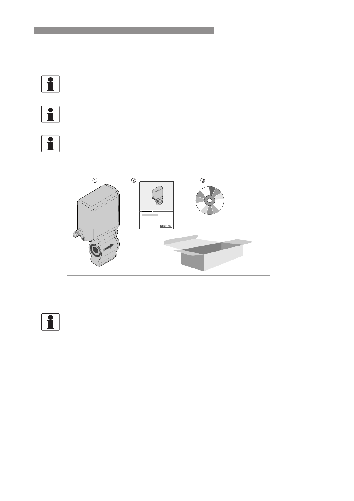
Figure 2-1: Scope of delivery
1 Flowmeter in ordered size
2 Product documentation (on request)
3 CD-ROM with product documentation
INFORMATION!
Assembly materials and tools are not part of the delivery. Use the assembly materials and tools
in compliance with the applicable occupational health and safety directives.
www.krohne.com05/2014 - 4000827703 - HB BATCHFLUX 5500 R03 en
7
Page 8
2 DEVICE DESCRIPTION
2.2 Device description
Your measuring device is supplied ready for operation. The factory settings for the operating
data have been made in accordance with your order specifications.
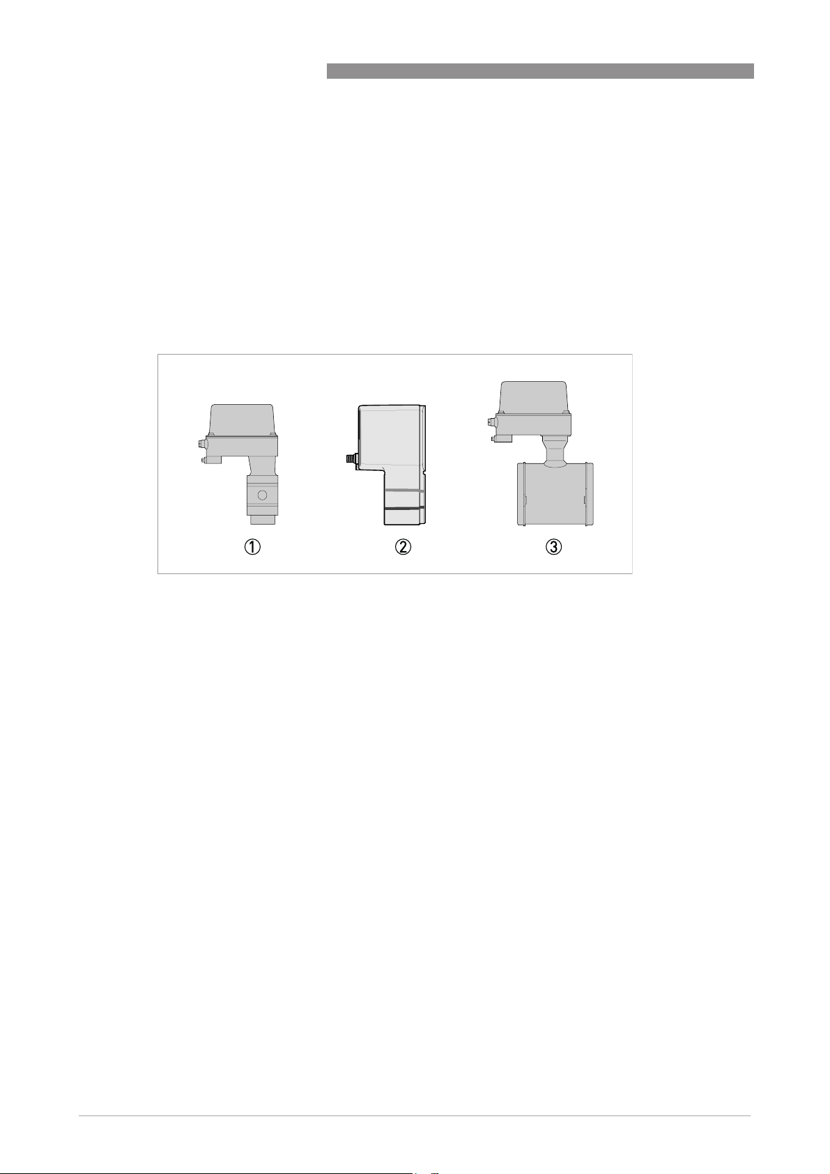
The following compact versions are available:
• Version 1: converter directly mounted on cast sensor housing in size DN2.5..6
• Version 2: converter and sensor in solid cast BNG construction for DN10 and DN 15
• Version 3: converter mounted on conventional sensor construction (DN25 and DN40)
BATCHFLUX 5500 C
Figure 2-2: Device version
1 DN2.5 - 4 - 6 (
2 DN10 - DN15 (
3 DN25 - DN40 ( 1 - 1
1
/10 -1 /6 -1 /4 " ).
3
/8 -1 /2 " ).
1
/2 " ).
8
www.krohne.com 05/2014 - 4000827703 - HB BATCHFLUX 5500 R03 en
Page 9

BATCHFLUX 5500 C
2.3 Nameplate
Figure 2-3: Nameplate
1 Name and address of the manufacturer
2 Type designation, S/N nr and year of manufacturing
3 Calibration and device data
4 Tag number
5 Marking ( ao. CE and 3-A logo )
6 Electrical values and software revision nr.
7 Output data
8 Additional info ( e.g. manufacturer website)
DEVICE DESCRIPTION 2
www.krohne.com05/2014 - 4000827703 - HB BATCHFLUX 5500 R03 en
9
Page 10

3 INSTALLATION
3.1 General notes on installation
INFORMATION!
Inspect the packaging carefully for damages or signs of rough handling. Report damage to the
carrier and to the local office of the manufacturer.
INFORMATION!
Do a check of the packing list to make sure that you have all the elements given in the order.
INFORMATION!
Look at the device nameplate to ensure that the device is delivered according to your order.
Check for the correct supply voltage printed on the nameplate.
3.2 Storage
• Store the device in a dry and dust-free location.
• Avoid lasting direct exposure to the sun.
• Store the device in its original packaging.
• Storage temperature: -50 ...+70°C / -58...+158°F
BATCHFLUX 5500 C
3.3 Pre-installation requirements
Make sure that you have all necessary tools available:
• Small wrench (M5) for connection to ground
• Torque wrench for installing flowmeter in pipeline
Assecoires necessary for the correct installations are available on request at the manufacturer
Make sure that these accesoires are available before starting installation;
• O- ring / L-ring gasket
• Special pipe flanges
• Stud bolt with lockwasher, plain washer and nut
INFORMATION!
To facilitate servicing and/or exchanging of the device, please note that:
it must be possible to shut off the flow through the pipeline ( control valve upstream in pipeline).
Drain the pipeline before removing device ( provide drain valve)
10
www.krohne.com 05/2014 - 4000827703 - HB BATCHFLUX 5500 R03 en
Page 11

BATCHFLUX 5500 C
3.4 General requirements
INFORMATION!
The following precautions must be taken to ensure reliable installation.
•
Make sure that there is adequate space to the sides.
•
Protect the signal converter from direct sunlight and install a sun shade if necessary.
•
Support the pipeline on both side of the flowmeter.
•
Do not expose the signal converter to intense vibration. The flowmeters are tested for a
vibration level in accordance with IEC 60068-2-64.
INSTALLATION 3
Figure 3-1: Avoid vibrations
Figure 3-2: Avoid strong magnetic fileds
Figure 3-3: Horizontal piperun
CAUTION!
Install in a slightly descending pipe section to prevent air from collecting and to avoid faulty
measurements (meter can drain).
www.krohne.com05/2014 - 4000827703 - HB BATCHFLUX 5500 R03 en
11
Page 12

3 INSTALLATION
3.5 Installation conditions
3.5.1 Inlet and outlet
Figure 3-4: Inlet and outlet section
1 ≥ 5 DN
2 ≥ 2 DN
3 Drain valve (to empty pipeline)
BATCHFLUX 5500 C
3
3.5.2 Control valve
Figure 3-5: Installation before control valve
3.5.3 Pump
12
Figure 3-6: Installation after pump
∠α > 2°
1. Drain valve (to empty pipeline)
www.krohne.com 05/2014 - 4000827703 - HB BATCHFLUX 5500 R03 en
Page 13

BATCHFLUX 5500 C
3.5.4 Open feed or discharge
Figure 3-7: Installation before an open discharge
3.5.5 Mounting position
INSTALLATION 3
Figure 3-8: Installation in bending pipes
∠α ; > 2°
1. Drain valve ( to empty pipeline)
CAUTION!
Avoid draining or partial filling of the flow sensor.
WARNING!
Vertical down position only in conjunction of a control valve
www.krohne.com05/2014 - 4000827703 - HB BATCHFLUX 5500 R03 en
13
Page 14

3 INSTALLATION
3.5.6 Mounting
3.5.7 Installation location
Figure 3-9: Installation location
CAUTION!
Mount the flow sensor in such a way that the electrode axis
(X--------X) is approximately in a horizontal pipe run.
BATCHFLUX 5500 C
3.5.8 Flange deviation
Figure 3-10: Mounting position and flange deviation
1 L
max
2 L
min
CAUTION!
Max. permissible deviation of pipe flange faces:
- L
L
max
≤ 0.5 mm / 0.02"
min
14
www.krohne.com 05/2014 - 4000827703 - HB BATCHFLUX 5500 R03 en
Page 15

BATCHFLUX 5500 C
3.5.9 Temperatures
Process temperature vs ambient temperature
1 Ambient temperature
2 Process temperature
3.5.10 Hot filling
INSTALLATION 3
Installation position
Figure 3-11: In case of hot fluids
INFORMATION!
Avoid installation near hot product tanks. If possible, try to insulate the flowmeter from radiant
heat sources.
CAUTION!
°
On high temperature pipes and where temperatures exceed 100
C, provide facilities to
compensate for longditudinal expansion of pipeline (due to heat-up). Use flexible pipe elements
(e.g. elbows).
www.krohne.com05/2014 - 4000827703 - HB BATCHFLUX 5500 R03 en
15
Page 16

4 ELECTRICAL CONNECTIONS
4.1 Safety instructions
DANGER!
All work on the electrical connections may only be carried out with the power disconnected. Take
note of the voltage data on the nameplate!
DANGER!
Observe the national regulations for electrical installations!
WARNING!
Observe without fail the local occupational health and safety regulations. Any work done on the
electrical components of the measuring device may only be carried out by properly trained
specialists.
INFORMATION!
Look at the device nameplate to ensure that the device is delivered according to your order.
Check for the correct supply voltage printed on the nameplate.
BATCHFLUX 5500 C
4.2 Grounding
CAUTION!
The grounding wire should not transmit any interference voltage. Therefore do not ground any
other electrical device at the same conductor.
CAUTION!
When connecting to functional extra-low voltages (24VDC) , ensure that you use protective
separation (PELV) according to IEC 364/IEC 536 or VDE 0100/VDE 0106.
16
www.krohne.com 05/2014 - 4000827703 - HB BATCHFLUX 5500 R03 en
Page 17

BATCHFLUX 5500 C
4.3 Electrical connection
4.3.1 Cable connector M12 - 5 pin
All operating data for the BATCHFLUX 5500 C are preset at the factory. For changing the
parameters and diagnostic purposes BATCHMon plus operation software can be used.
ELECTRICAL CONNECTIONS 4
1 +24 VDC
2 Frequency output
3 Frequency output (ground)
4 Ground
5 To be connected for servicing only
Use one of the following attachment plug types to connect the flowmeter to a third
party system:
• moulded plug, straight or angle-entry form
• integrally extruded plug with cable in various lengths
• moulded plug, straight form, especially suitable for high-interference environments
Possible vendors of these plugs are:
• Binder
• Hirschmann
• Lumberg
• Amphenol
• Coninvers
www.krohne.com05/2014 - 4000827703 - HB BATCHFLUX 5500 R03 en
17
Page 18

4 ELECTRICAL CONNECTIONS
4.3.2 Cable connector M12 - 8 pin (with status output)
The 8 pin electric connection has a status output. This status output, is configurable to customer
specifications and offers either the flow direction (of the medium) or an error signal.
1 + 24 VDC
2 Not Connected
3 To be connected for servicing only
4 Ground
5 Frequency output
6 Ground common I/O
7 Status output
8 Not Connected
BATCHFLUX 5500 C
Options on status output 7; Off / Error / Flow direction
Mode
• Status output On / Off
• Flow direction
- Default value :Flow Direction
- Forward flow : status output; open
- Reversed flow ; status output ; closed
• Error software / application failure
Error signaling for following events: software failure or application failure (detection of empty
pipe only). No error ; status output open
18
www.krohne.com 05/2014 - 4000827703 - HB BATCHFLUX 5500 R03 en
Page 19

BATCHFLUX 5500 C
5.1 Spare parts availability
The manufacturer adheres to the basic principle that functionally adequate spare parts for each
device or each important accessory part will be kept available for a period of 3 years after
delivery of the last production run for the device.
This regulation only applies to spare parts which are subject to wear and tear under normal
operating conditions.
5.2 Availability of services
The manufacturer offers a range of services to support the customer after expiration of the
warranty. These include repair, maintenance, technical support and training.
INFORMATION!
For more precise information, please contact your local sales office.
5.3 Returning the device to the manufacturer
SERVICE 5
5.3.1 General information
This device has been carefully manufactured and tested. If installed and operated in accordance
with these operating instructions, it will rarely present any problems.
CAUTION!
Should you nevertheless need to return a device for inspection or repair, please pay strict
attention to the following points:
•
Due to statutory regulations on environmental protection and safeguarding the health and
safety of our personnel, manufacturer may only handle, test and repair returned devices that
have been in contact with products without risk to personnel and environment.
•
This means that the manufacturer can only service this device if it is accompanied by the
following certificate (see next section) confirming that the device is safe to handle.
CAUTION!
If the device has been operated with toxic, caustic, flammable or water-endangering products,
you are kindly requested:
•
to check and ensure, if necessary by rinsing or neutralising, that all cavities are free from
such dangerous substances,
•
to enclose a certificate with the device confirming that is safe to handle and stating the
product used.
www.krohne.com05/2014 - 4000827703 - HB BATCHFLUX 5500 R03 en
19
Page 20

5 SERVICE
5.3.2 Form (for copying) to accompany a returned device
Company: Address:
Department: Name:
Tel. no.: Fax no.:
Manufacturer's order no. or serial no.:
The device has been operated with the following medium:
BATCHFLUX 5500 C
This medium is: water-hazardous
toxic
caustic
flammable
We checked that all cavities in the device are free from such
substances.
We have flushed out and neutralized all cavities in the
device.
We hereby confirm that there is no risk to persons or the environment through any residual media
contained in the device when it is returned.
Date: Signature:
Stamp:
5.4 Disposal
CAUTION!
Disposal must be carried out in accordance with legislation applicable in your country.
20
www.krohne.com 05/2014 - 4000827703 - HB BATCHFLUX 5500 R03 en
Page 21

BATCHFLUX 5500 C
6.1 Measuring principle
An electrically conductive fluid flows inside an electrically insulated pipe through a magnetic
field. This magnetic field is generated by a current, flowing through a pair of field coils.
Inside of the fluid, a voltage U is generated:
U = v * k * B * D
U = v * k * B * D
U = v * k * B * DU = v * k * B * D
in which:
v = mean flow velocity
k = factor correcting for geometry
B = magnetic field strength
D = inner diameter of flow meter
The signal voltage U is picked off by electrodes and is proportional to the mean flow velocity v
and thus the flow rate q. A signal converter is used to amplify the signal voltage, filter it and
convert it into signals for totalising, recording and output processing.
TECHNICAL DATA 6
Figure 6-1: Measuring principle
1 Induced voltage (proportional to flow velocity)
2 Electrodes
3 Magnetic field
4 Field coils
www.krohne.com05/2014 - 4000827703 - HB BATCHFLUX 5500 R03 en
21
Page 22

6 TECHNICAL DATA
6.2 Technical data
INFORMATION!
•
The following data is provided for general applications. If you require data that is more
relevant to your specific application, please contact us or your local sales office.
•
Additional information (certificates, special tools, software,...) and complete product
documentation can be downloaded free of charge from the website (Download Center).
Measuring system
Measuring principle Faraday's law
Application range Electrically conductive fluids
Measured value
Measured value
Measured valueMeasured value
Primary measured value Flow velocity
Secondary measured value Volume flow
Design
Features Tube: Zirconium oxide
Modular construction The measurement system consists of a flow sensor and a signal
Compact version BATCHFLUX 5500 C
Nominal diameter DN2.5...40 / 0.1...1½"
Measurement range -12...+12 m/s / -39...+39 ft/s
User interface
User interface
User interfaceUser interface
Operating data Factory set to customer specification.
Human Machine Interface (HMI) Option: BATCHMon Plus software
Cable connections Standard; 1x M12, 5-pin connector
BATCHFLUX 5500 C
Electrodes: Fused-in cermet (DN2.5...15) / Platinum (DN25...40)
Standard wet calibration
converter. It is only available as compact version.
With status output; 1x M12, 8-pin connector
22
www.krohne.com 05/2014 - 4000827703 - HB BATCHFLUX 5500 R03 en
Page 23

BATCHFLUX 5500 C
Measuring accuracy
Reference conditions Medium: water
Error limits at reference conditions for tap water, 400
Error limits at reference conditions for tap water, 400 µS/cm, 20
Error limits at reference conditions for tap water, 400Error limits at reference conditions for tap water, 400
Maximum measuring error DN2.5...6:
Repeatability DN2.5...6 / DN25...40:
Error limits at reference conditions for hot water, 400
Error limits at reference conditions for hot water, 400 µS/cm, 80
Error limits at reference conditions for hot water, 400Error limits at reference conditions for hot water, 400
Maximum measuring error DN10...15:
Repeatability DN10...15:
TECHNICAL DATA 6
Inlet / outlet section: 10 DN / 5 DN
Valve closing time variation: < 1 ms
Flow velocity: 1 m/s, flow conditions similar to EN 29104
Operating pressure: 1 bar / 14.5 psi
S/cm, 20°C / 68
S/cm, 20S/cm, 20
DN2.5...6:
DN2.5...6:DN2.5...6:
v ≤ 1 m/s: ±0.4% of measured value + 1 mm/s
v > 1 m/s: ±0.5% of measured value
DN10...15:
DN10...15:
DN10...15:DN10...15:
±0.2% of measured value + 1 mm/s
DN25...40:
DN25...40:
DN25...40:DN25...40:
v ≤ 1 m/s: ±0.2% of measured value + 1 mm/s
v > 1 m/s: ±0.3% of measured value
DN2.5...6 / DN25...40: Standard deviation:
DN2.5...6 / DN25...40:DN2.5...6 / DN25...40:
Filling time 1.5...3 s: ≤ 0.4%
Filling time 3...5 s: ≤ 0.2%
Filling time > 5 s: ≤ 0.1%
DN10...15:
DN10...15: Standard deviation:
DN10...15:DN10...15:
Filling time 1.5...3 s: ≤ 0.3%
Filling time 3...5 s: ≤ 0.15%
Filling time > 5 s: ≤ 0.08%
S/cm, 80°C / 176
S/cm, 80S/cm, 80
DN10...15:
DN10...15:DN10...15:
±0.2% of measured value + 1 mm/s
DN10...15: Standard deviation:
DN10...15:DN10...15:
Filling time 1.5...3 s: ≤ 0.3%
Filling time 3...5 s: ≤ 0.2%
Filling time > 5 s: ≤ 0.1%
C / 68°FFFF:
C / 68C / 68
Standard deviation:
Standard deviation:Standard deviation:
Standard deviation:
Standard deviation:Standard deviation:
C / 176°FFFF:
C / 176C / 176
Standard deviation:
Standard deviation:Standard deviation:
www.krohne.com05/2014 - 4000827703 - HB BATCHFLUX 5500 R03 en
23
Page 24

6 TECHNICAL DATA
Operating conditions
Temperature
Temperature
TemperatureTemperature
Process temperature Dependent on ambient temperature. See chapter "Temperatures".
Cleaning temperature SIP: Maximum 1 hour at 150°C / +302°F
Shock ≤ 3K/s
Ambient temperature -40…+60°C/ -40…+140°F
Storage temperature -50…+70°C/ -58…+158°F
Pressure
Pressure
PressurePressure
Ambient Atmospheric
Process pressure up to 16 bar / 232 psi for DN10...15
Vacuum load 0mbara / 0psig
Chemical properties
Chemical properties
Chemical propertiesChemical properties
Physical condition Liquids
Electrical conductivity ≥ 5 μS/cm (≥ 20 μS/cm for demineralised water)
Recommended flow velocity -12...+12 m/s / -39...+39 ft/s
BATCHFLUX 5500 C
CIP: Maximum 1 hour at 140°C / +284°F
up to 40 bar / 580 psi for DN2.5...6 / DN25...40
Installation conditions
Installation For detailed information see chapter "Installation".
Inlet run ≥ 5 DN
Outlet run ≥ 2 DN
Dimensions and weights For detailed information see chapter "Dimensions and weights".
Materials
Sensor- and converter housing Stainless steel 1.4404 / 1.4408
Measuring tube Fused in-place
Measuring electrodes DN2.5...15: Cermet
DN25...40: Platinum
Process connections
Connection Sandwich design
Optional: Pressure relief groove at flange facing of the sensor
Construction drawings of recommenced counter flanges are
available from download centre.
24
www.krohne.com 05/2014 - 4000827703 - HB BATCHFLUX 5500 R03 en
Page 25

BATCHFLUX 5500 C
Electrical connections
Power supply 24 VDC ± 25%
Power consumption ≤ 3 W
Switch on current ≤ 5 A (< 100 μs) at 24 VDC
Voltage loss Possible for a maximum of 20 ms according to NAMUR NE21.
BATCHMON Plus For parameter setting and diagnostic purposes, communication via
Status output Configurable; error, flow direction, on/off
Frequency output
Frequency output
Frequency outputFrequency output
Type Frequency (passive) / galvanically isolated from power supply
Function All operating data preset at factory.
Interval Counter gate time ≥ 1000 / (P
Frequency output ≤ 10 kHz
Pulse width at full scale value ≤ 10 Hz: 50, 100, 200 or 500 ms
Passive operation Connection of electronic or electromechanical counters.
Low flow cut-off Threshold: 0...20%
TECHNICAL DATA 6
PC with a single device (optional)
[Hz])
100%
> 10 Hz: automatic, pulse width = 1 / (2 x f
External voltage: ≤ 30 VDC / ≤ 24 VAC
Load: I
Hysteresis: 0...20%
Hysteresis ≤ threshold
Depending on customers specifications.
max
≤ 20 mA
) or symmetrical, 1:1
100%
Approvals and certifications
CE
CE
CECE
This device fulfills the statutory requirements of the EC directives.
The manufacturer certifies successful testing of the product by
applying the CE mark.
Electromagnetic compatibility Directive: 2004/108/EC
Harmonized standard: EN 61326-1: 2006
Low voltage directive Directive: 2006/95/EC
Harmonized standard: EN 61010: 2010
Pressure equipment directive Directive: 97/23/EC
Category SEP
Fluid group 1
Production module H
Other approvals and standards
Other approvals and standards
Other approvals and standardsOther approvals and standards
Protection category acc. to
IEC 529 / EN 60529
Shock test IEC 60068-2-27
Vibration test IEC 60068-2-64
Hygienic DN2.5...15: 3A
DN2.5...6 / DN25...40: IP 66/67
DN10...15: IP 69K
FDA approved materials
www.krohne.com05/2014 - 4000827703 - HB BATCHFLUX 5500 R03 en
25
Page 26

6 TECHNICAL DATA
6.3 Dimensions and weights
DN2.5...6
Figure 6-2: Dimensions
1 (Grounding)
2 M12; 5 - 8 pins connector
BATCHFLUX 5500 C
Nominal
size
Dimensions [mm] Weight
[kg]
a b c d e f g h i
DN2.5 50 156 206 6 → 2.5 44 88 141 128 54 1.5
DN4 50 156 206 7 → 3.2 44 88 141 128 54 1.6
DN6 50 156 206 9 → 4.8 44 88 141 128 54 1.6
Note on dimension d: As the diameter reduces to the middle, the diameter is specified for the inlet and
for the middle
Nominal
size
Dimensions [inches] Weight
[lb]
a b c d e f g h i
1/10" 1.97 6.14 8.11 0.24 → 0.10 1.73 3.46 5.55 5.0 2.13 3.4
1/6" 1.97 6.14 8.11 0.28 → 0.13 1.73 3.46 5.55 5.0 2.13 3.6
1/4" 1.97 6.14 8.11 0.35 → 0.19 1.73 3.46 5.55 5.0 2.13 3.6
Note on dimension d: As the diameter reduces to the middle, the diameter is specified for the inlet and
for the middle
26
www.krohne.com 05/2014 - 4000827703 - HB BATCHFLUX 5500 R03 en
Page 27

BATCHFLUX 5500 C
DN10...15
1 (Grounding)
2 M12; 5 - 8 pins connector
TECHNICAL DATA 6
Nominal
size
Dimensions [mm] Weight
[kg]
a b c d e f g h i
DN10 50 140 179 10.5 → 8 45.4 60 106.5 88 54 1.4
DN15 50 140 179 14 → 12 45.4 60 106.5 88 54 1.4
Note on dimension d: As the diameter reduces to the middle, the diameter is specified for the inlet and
for the middle
Nominal
size
Dimensions [inches] Weight
[lb]
a b c d e f g h i
3/8" 1.97 5.51 7.05 0.41 → 0.31 1.79 2.36 4.19 3.46 2.13 3.1
1/2" 1.97 5.51 7.05 0.55 → 0.47 1.79 2.36 4.19 3.46 2.13 3.1
Note on dimension d: As the diameter reduces to the middle, the diameter is specified for the inlet and
for the middle
www.krohne.com05/2014 - 4000827703 - HB BATCHFLUX 5500 R03 en
27
Page 28

6 TECHNICAL DATA
DN25..40
Figure 6-3: Dimensions
1 (Grounding)
2 M12; 5 - 8 pins connector
BATCHFLUX 5500 C
Nominal
Dimensions [mm] Weight [kg]
size
a b c d e f g h i
DN25 50 170 204 26 → 20 68 102 141 128 58 1.6
DN40 50 177 219 39 → 30 84 117 141 128 83 2.3
Note on dimension d: As the diameter reduces to the middle, the diameter is specified for the inlet and
for the middle
Nominal
Dimensions [inches] Weight [lb]
size
a b c d e f g h i
1" 1.97 6.69 8.03 1.02 → 0.79 2.68 4.02 5.55 5.04 2.28 3.6
1 1/2" 1.97 6.97 8.62 1.54 → 1.18 3.30 4.61 5.55 5.04 3.27 5.1
Note on dimension d: As the diameter reduces to the middle, the diameter is specified for the inlet and
for the middle
28
www.krohne.com 05/2014 - 4000827703 - HB BATCHFLUX 5500 R03 en
Page 29

BATCHFLUX 5500 C
6.4 Counter Flanges
The BATCHFLUX 5500 can be mounted between various types of counter flanges.
TECHNICAL DATA 6
Sizes of flanges
DN a [mm] b [mm] c [mm] d [mm] O-ring
Flange 1 2,5...10 * see table
below
Flange 2 15 Ø 14.2 Ø 19.2 Ø 26.6 Ø 30.4 15.47 *
Flange 3 25 Ø 25 Ø 31.3 Ø 41.2 Ø 49.2 15.47 *
Size DN
2,5 Ø 10 Ø 6.2 Ø 11.1 Ø 18.4
4 Ø 10 Ø 7.2 Ø 12.1 Ø 19.4
6 Ø 10 Ø 9.2 Ø 14.2 Ø 21.5
10 Ø 10 Ø 10.7 Ø 15.7 Ø 23
a1[mm] a2 [mm]
* see table below * see table
below
b [mm] c [mm]
Ø 30.4 Special L-
ring
3.53
3.53
Note; flanges must be fully welded and surface roughness, grinded and polished ( roughness
0,8). See for more information the 3A CCE 2007-2 Coordination Bulletin.
INFORMATION!
The O-rings require periodic inspection and replacement. As the interval depends on processspecific variables, the length of the interval cannot be specified.
The O-rings are not part of the portfolio of KROHNE.
INFORMATION!
For 3A applications, O-rings must conform to the requirements of the 3A sanitary standard for
Flow meters, number 28-04 Class I or Class II (max. 8% milk fat).
The used O-rings must also withstand the processing, sterilization and chemical conditions for
the intended use ( for more information, contact the manufacturer)
www.krohne.com05/2014 - 4000827703 - HB BATCHFLUX 5500 R03 en
29
Page 30

6 TECHNICAL DATA
Reference to specific dimensions and drawing numbers
Size DN Pcd [mm] D [mm] W [mm] Drawing number
2,5 Ø 56 Ø 68 14.5 4000587801
4 Ø 56 Ø 68 14.5 4000587807
6 Ø 56 Ø 68 14.5 4000587810
10 Ø 56 Ø 68 14.5 4000587815
15 Ø 56 Ø 68 14.9 4000587818
25 Ø 84 Ø 104 16.5 4000587824
40 # # # #
# Dimensions for DN40; on request
INFORMATION!
Detailed construction drawings of the above sketches are available from the download centre
( see table for drawing numbers)
BATCHFLUX 5500 C
30
www.krohne.com 05/2014 - 4000827703 - HB BATCHFLUX 5500 R03 en
Page 31

BATCHFLUX 5500 C
NOTES 7
www.krohne.com05/2014 - 4000827703 - HB BATCHFLUX 5500 R03 en
31
Page 32

KROHNE product overview
• Electromagnetic flowmeters
• Variable area flowmeters
• Ultrasonic flowmeters
• Mass flowmeters
• Vortex flowmeters
• Flow controllers
• Level meters
• Temperature assemblies
• Pressure transmitters
• Analysis products
• Products and systems for the oil & gas industry
• Measuring systems for the marine industry
Head Office KROHNE Messtechnik GmbH
Ludwig-Krohne-Str. 5
47058 Duisburg (Germany)
Tel.:+49 203 301 0
Fax:+49 203 301 103 89
info@krohne.com
© KROHNE 05/2014 - 4000827703 - HB BATCHFLUX 5500 R03 en - Subject to change without notice.
The current list of all KROHNE contacts and addresses can be found at:
www.krohne.com
 Loading...