

Page 1
Introduction
On Value
Off Value
Attack Time
Release Time
CC Value
Time
Thank you for purchasing the Korg nanoKONTROL slim-line USB controller. To help
you get the most out of your new instrument, please read this manual carefully.
In order to use the functions of this product, you’ll need to make settings
in the application you’re using. Make settings as described in the owner’s
manual for your application.
Parts and their functions
5
2
3
1. MIDI control group
A knob, slider, two buttons (button 1 and button 2) are collectively called a
MIDI control group. The nanoKONTROL has nine MIDI control groups.
a. Knob
This knob transmits control change messages.
b. Slider
This slider transmits control change messages.
c. Button 1 / Button 2
These buttons transmit control change messages or note messages.
2. Transport button
There are six transport buttons: [REW], [PLAY], [FF], [LOOP], [STOP], and
[REC]. These buttons transmit control change messages or MMC (MIDI Machine Control) messages.
3. [SCENE] button
Use this button to switch between the four scenes.
A “scene” is a set of parameter assignments for the controllers (sliders and
knobs, etc.) so that the controllers can be used to operate your DAW or software synthesizer. The nanoKONTROL has four scenes. The four scenes are
collectively called a “scene set.”
You can use KORG KONTROL Editor to change the assignment of each
controller. (➞ “Making detailed settings”)
4. Scene LEDs
The LED of the selected scene will light up.
5. USB connector
Connect the nanoKONTROL to your computer with a USB cable via this port.
b
a
c
1
4
Setup
Operating requirements
Mac OS X
Computer
Operating system
Windows
Computer
Operating system
Apple Macintosh computer with an Intel or PowerPC
processor that has a USB port and satisfies the
requirements for running Mac OS X
Mac OS X 10.3.9, or Mac OS X 10.4.7 or later
Computer that has a USB port and satisfied the
requirements for running Microsoft Windows XP/
Vista (a USB chipset made by the Intel Corporation is
recommended)
Microsoft Windows XP SP2 or later, or Microsoft
Windows Vista SP1
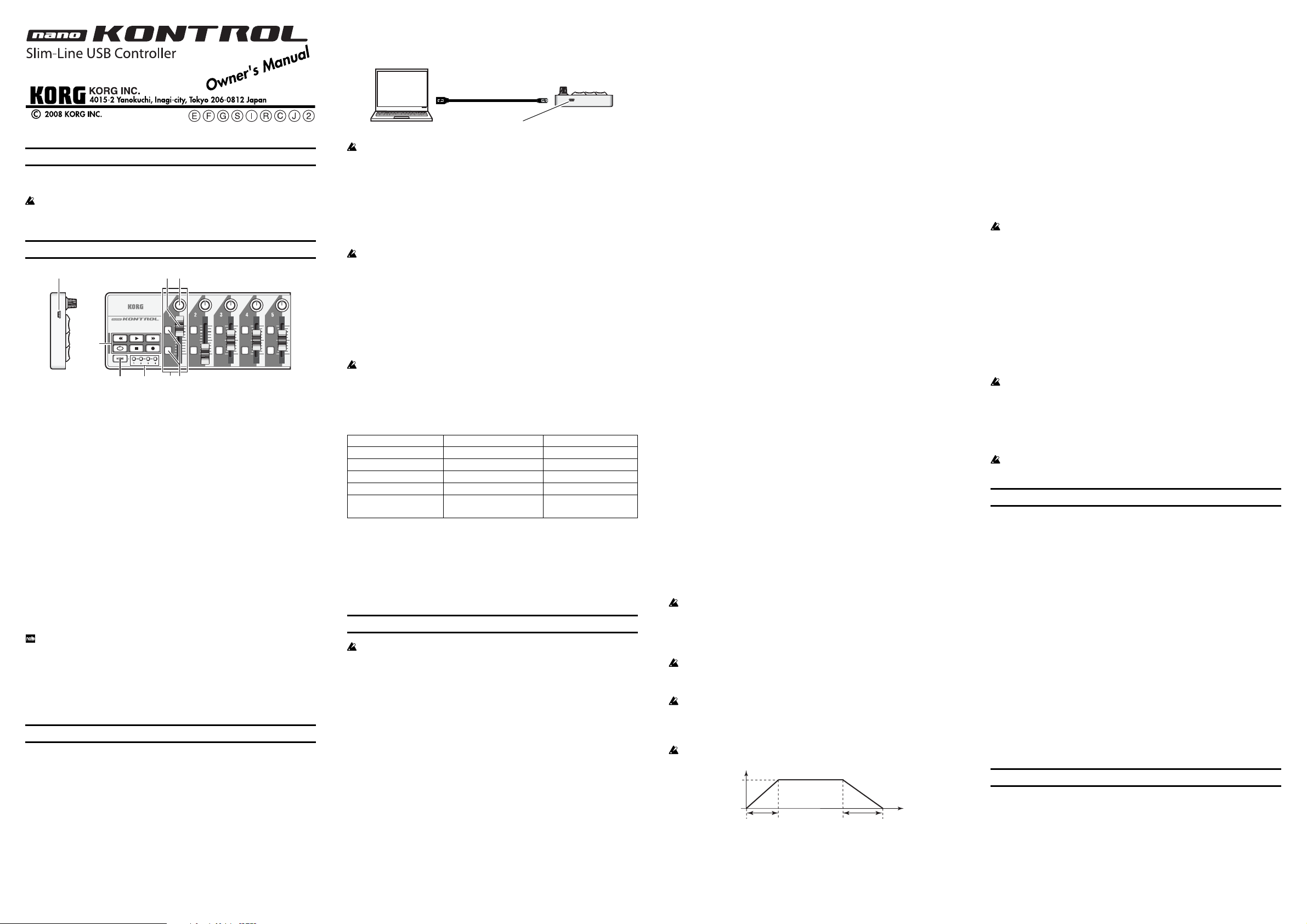
Connections and power
Connect the nanoKONTROL to your computer via a USB cable.
The power will turn on, and a scene LED will light up.
USB cable
Computer
If you’re using a passive (non-powered) USB hub, the nanoKONTROL may
fail to power-on because it is not getting enough power. If this is so, please
connect the nanoKONTROL to a powered USB hub or directly to your
computer.
USB connector
nanoKONTROL
Installing the driver
Installation
When you first connect the nanoKONTROL to your computer, the standard
USB-MIDI driver for your operating system will be installed automatically.
If you’re using Microsoft Windows XP/Vista, the USB-MIDI driver that is
automatically installed won’t allow you to use the nanoKONTROL with
multiple applications simultaneously. If you want to use the
nanoKONTROL with multiple applications simultaneously, you’ll need
to install the Korg USB-MIDI driver. Even if you don’t need to use the
nanoKONTROL with multiple applications simultaneously, we
recommend that you install the Korg USB-MIDI driver for more stable
operation. Download the Korg USB-MIDI driver from the Korg website,
and install it as described in the included documentation.
(http://www.korg.co.jp/English/Distributors/ or http://www.korg.com)
If you want to use Korg Kontrol Editor, you’ll need to install the Korg
USB-MIDI driver.
Driver ports
The nanoKONTROL’s USB-MIDI I/O will be seen from the computer as 1IN-1OUT.
As shown in the following table, the name of the ports depend on which operating
system you’re using, and whether or not you’ve installed the Korg USB-MIDI driver.
OS MIDI IN MIDI OUT
Mac OS X 10.3 or 10.4 nanoKONTROL Port 1 nanoKONTROL Port 1
Mac OS X 10.5 or later
Windows XP USB audio device USB audio device
Windows Vista nanoKONTROL nanoKONTROL
Windows XP/Vista +
KORG USB-MIDI Driver
MIDI IN port
MIDI messages from the nanoKONTROL’s various controllers are received
here. If you want to use the nanoKONTROL to control an application on your
computer, select this port in the MIDI input settings of your application.
This is also used by the Korg Kontrol Editor to control the nanoKONTROL.
MIDI OUT port
This is used by the Korg Kontrol Editor to control the nanoKONTROL.
nanoKONTROL SLIDER/KNOB
nanoKONTROL 1 SLIDER/KNOB
nanoKONTROL CTRL
nanoKONTROL 1 CTRL
Making detailed settings
The following settings cannot be edited from the nanoKONTROL itself, so
you’ll need to use the Korg Kontrol Editor. You can download the Korg
Kontrol Editor from the Korg website.
(http://www.korg.co.jp/English/Distributors/ or http://www.korg.com)
Scene MIDI channel
Scene MIDI Channel [1...16]
Specifies the MIDI transmit channel for each scene. Set this to match the MIDI
channel of the MIDI application you’re controlling.
Group MIDI channel
Group MIDI Channel [1...16/Scene MIDI Channel]
Specifies the MIDI channel on which each MIDI control group will transmit
MIDI messages. Set this to match the MIDI channel of the MIDI application
you’re controlling. If you set this to “Scene MIDI Channel,” messages will be
transmitted on the Scene MIDI Channel.
Knobs
Operating a knob will transmit a control change message.
You can enable/disable each knob, specify its control change number, and
specify the values transmitted when the knob is turned fully left or fully right.
Knob Enable [Disable/Enable]
Enables or disables the knob.
If you’ve disabled a knob, turning it will not transmit a MIDI message.
Control Change Number [0...127]
Specifies the control change number of the control change message that is transmitted.
Left Value [0...127]
Specifies the value of the control change message transmitted when you turn
the knob all the way to the left.
Right Value [0...127]
Specifies the value of the control change message transmitted when you turn
the knob all the way to the right.
Sliders
Operating a slider will transmit a control change message.
You can enable/disable each slider, specify its control change number, and
specify the values transmitted when the slider is moved fully upward or fully
downward.
Slider Enable [Disable/Enable]
Enables or disables the slider.
If you’ve disabled a slider, moving it will not transmit a MIDI message.
Control Change Number [0...127]
Specifies the control change number of the control change message that is transmitted.
Upper Value [0...127]
Specifies the value of the control change message transmitted when you move
the slider all the way upward.
Lower Value [0...127]
Specifies the value of the control change message transmitted when you move
the slider all the way downward.
Button 1 / Button 2
Operating a button will transmit either a control change message or a note
message, depending on the Assign Type you’ve specified.
You can specify the message assigned to each button, the way in which the button
will operate when pressed, the control change number, the note number, the value
transmitted when the button is turned on/off, and the attack time/release time.
Assign Type [No Assign/Control Change/Note]
Specifies the message assigned to the slider.
You can choose disabled, control change message, or note message.
Button Behavior [Momentary/Toggle]
Selects one of two types of behavior for the button.
Momentary
Tog gle
Control Change Number [0...127]
Specifies the control change number of the control change message that is transmitted.
Note Number [C-1...G9]
Specifies the note number of the note message that is transmitted.
On Value [0...127]
Specifies the value of the message transmitted when the button turns on.
If the assign type is set to “Note,” the velocity of the note-on message is
specified by the On Value setting.
If the On Value is “0,” the velocity will be transmitted as “1.”
Off Value [0...127]
Specifies the value of the message transmitted when the button turns off.
This can be set only if the assign type is “Control Change.”
Attack Time [0...127]
Specifies the time from when you press the button until the On Value is reached.
This can be set only if the assign type is “Control Change.”
Release Time [0...127]
Specifies the time from when you release the button until the Off Value is
reached.
This can be set only if the assign type is “Control Change.”
Pressing the button will transmit the On value or Note-on
message. Releasing the button will transmit the Off value or
Note-off message.
Each time you press the button, the On value/Note-on or the
Off Value/Note-off message will be transmitted alternately.
Transport buttons
Operating the transport buttons will transmit either control change messages
or MMC messages, depending on the assign type.
For each of these six buttons, you can specify the message that is assigned, the
way in which the button will operate when pressed, the control change number, or an MMC command.
Transport MIDI Channel [1...16/Scene MIDI Channel]
Specifies the MIDI channel on which MIDI messages will be transmitted when
you operate the transport button.
Set this to match the MIDI channel of the MIDI application you’re controlling.
If you set this to “Scene MIDI Channel,” the message will be transmitted on
the Scene MIDI Channel.
Assign Type [Control Change/MMC/No Assign]
Specifies the type of message assigned to the transport button.
You can specify that the button be disabled, or assign a control change message or MMC message.
Button Behavior [Momentary/Toggle]
Selects one of two types of behavior for the button.
Momentary
Tog gle
You can’t specify the button behavior if the assign type is “MMC.” If you’ve
specified “MMC,” an MMC command will be transmitted each time you
press the button.
Control Change Number [0...127]
Specifies the control change number of the control change message that is transmitted.
MMC Command [Stop/Play .../MMC Reset]
Selects one of the following thirteen types of MMC command as the MMC
message that will be transmitted.
Stop, Play, Deferred Play, Fast Forward, Rewind, Record Strobe, Record Exit,
Record Pause, Pause, Eject, Chase, Command Error Reset, MMC Reset
MMC Device ID [0...127]
Specifies the device ID of the MMC message.
Normally you will specify 127. If the device ID is 127, all devices will receive
the MMC message.
A control change message with a value of 127 will be
transmitted when you press the transport button, and with a
value of 0 when you release the button.
Each time you press the transport button, a control change
message with a value of 127 or 0 will be transmitted alternately.
Restoring the factory settings
If you turn on the power while holding down the [REC] button, [STOP] button, and [SCENE] button, the settings of the nanoKONTROL will return to
their factory-set condition, and the scene LEDs will light up.
The process of restoring the factory settings will take several seconds after
you turn on the power. You must not turn off the power during this time.
Troubleshooting
Power does not turn on
- If you’re using a passive (non-powered) USB hub, the nanoKONTROL may fail to
power-on because it is not getting enough power. If this is so, please connect the
nanoKONTROL to a powered USB hub or directly to your computer.
Software does not respond
- Make sure that the nanoKONTROL has been detected by the computer. If
you’re using Windows XP, go to the Control Panel, open “Sounds and Audio
Devices,” and check the “Hardware” tab page.
If you’re using Windows Vista, go to the Control Panel, open “Hardware
and Sounds” ➞ “View Hardware and Devices” ➞ “Device Manager,” and
check the “Sound, Video, and Game Controllers” tab.
If you’re using Mac OS X, open “Applications” ➞ “Utilities” ➞ “Audio MIDI
Setup,” and check the “MIDI Devices” tab page.
- Make sure that the nanoKONTROL is selected in the MIDI port settings of
the application you’re using.
- The application you’re using might not support a specific function. Check
the owner’s manual of your application.
- In order to use the functions of this product, you’ll need to make settings in
the application you’re using. Make settings as described in the owner’s
manual for your application.
Specifications
Connectors: USB connector (mini B type)
Power supply: USB bus power mode
Current consumption: 100 mA or less
Dimensions (W x D x H): 12.6 x 3.2 x 1.2 inches / 320 x 82 x 29.5 mm
Weight: 10.2 oz / 290 g
Included items: USB cable, Owner’s manual
* Specifications and appearance are subject to change without notice for
improvement.
 Loading...