

Page 1
Page 2

Page 3
Table of Contents
Precautions...................................................................... 4
Main features .................................................................. 5
How the sound generator is structured .............................5
The three elements of sound (pitch, timbre, and volume) ................... 5
Block diagram ......................................................................................................... 6
Getting started ................................................................ 7
Installing batteries ................................................................................................ 7
Using an AC adapter ............................................................................................ 7
Battery level indication ....................................................................................... 7
Connections ............................................................................................................ 8
Turning the power on .......................................................................................... 9
Turning the power off ......................................................................................... 9
Auto power-off ....................................................................................................... 9
Panel description and functions...................................... 10
Synthesizer section ............................................................................................ 10
Sequencer section ............................................................................................. 13
Global menu..................................................................16
Setting procedure .............................................................................................. 16
Specifications.................................................................17
Thank you for purchasing the Korg monotribe analogue rib-
bon station.
To help you get the most out of your new instrument, please
read this manual carefully.
Page 4

Precautions
Location
Using the unit in the following locations can result in a malfunction.
• In direct sunlight
• Locations of extreme temperature or humidity
• Excessively dusty or dirty locations
• Locations of excessive vibration
• Close to magnetic fields
Power supply
Please connect the designated AC adapter to an AC outlet of the correct voltage.
Do not connect it to an AC outlet of voltage other than that for which your unit is
intended.
Interference with other electrical devices
Radios and televisions placed nearby may experience reception interference.
Operate this unit at a suitable distance from radios and televisions.
Handling
To avoid breakage, do not apply excessive force to the switches or controls.
Care
If the exterior becomes dirty, wipe it with a clean, dry cloth. Do not use liquid
cleaners such as benzene or thinner, or cleaning compounds or flammable
polishes.
Keep this manual
After reading this manual, please keep it for later reference.
Keeping foreign matter out of your equipment
Never set any container with liquid in it near this equipment. If liquid gets into the
equipment, it could cause a breakdown, fire, or electrical shock.
Be careful not to let metal objects get into the equipment. If something does slip
into the equipment, unplug the AC adapter from the wall outlet. Then contact your
nearest Korg dealer or the store where the equipment was purchased.
Notice regarding disposal (EU only)
When this “crossed-out wheeled bin” symbol is displayed on the
product, owner’s manual, battery, or battery package, it signifies that
when you wish to dispose of this product, manual, package or battery
you must do so in an approved manner. Do not discard this product,
manual, package or battery along with ordinary household waste.
Disposing in the correct manner will prevent harm to human health
and potential damage to the environment. Since the correct method
of disposal will depend on the applicable laws and regulations in your
locality, please contact your local administrative body for details. If the battery
contains heavy metals in excess of the regulated amount, a chemical symbol
is displayed below the “crossed-out wheeled bin” symbol on the battery or
battery package.
4
THE FCC REGULATION WARNING (for USA)
This equipment has been tested and found to comply with the limits for a
Class B digital device, pursuant to Part 15 of the FCC Rules. These limits are
designed to provide reasonable protection against harmful interference in a
residential installation. This equipment generates, uses, and can radiate radio
frequency energy and, if not installed and used in accordance with the
instructions, may cause harmful interference to radio communications.
However, there is no guarantee that interference will not occur in a particular
installation. If this equipment does cause harmful interference to radio or
television reception, which can be determined by turning the equipment off
and on, the user is encouraged to try to correct the interference by one or
more of the following measures:
•Reorient or relocate the receiving antenna.
• Increase the separation between the equipment and receiver.
•Connect the equipment into an outlet on a circuit different from that to
which the receiver is connected.
•Consult the dealer or an experienced radio/TV technician for help.
Unauthorized changes or modification to this system can void the user’s
authority to operate this equipment.
This product has been manufactured according to strict specifications and
voltage requirements that are applicable in the country in which it is intended
that this product should be used. If you have purchased this product via the
internet, through mail order, and/or via a telephone sale, you must verify that
this product is intended to be used in the country in which you reside.
WARNING: Use of this product in any country other than that for which it is
intended could be dangerous and could invalidate the manufacturer’s or
distributor’s warranty.
Please also retain your receipt as proof of purchase otherwise your product may
be disqualified from the manufacturer’s or distributor’s warranty.
*All product names and company names are the trademarks or registered
trademarks of their respective owners.
IMPORTANT NOTICE TO CONSUMERS
Page 5

Main features
Analog synthesis
The VCO, VCF, and VCA are constructed of analog circuitry. With
intuitively simple operation and the sound-creating process that’s
distinctive of analog synthesizers, the monotribe gives you a flexible
and highly improvisatory synthesis experience. The VCF features the
filter circuit of the classic Korg MS-20.
Self-tuning function
When not producing sound, the monotribe tunes itself internally to
correct any pitch drift that may occur due to temperature changes or
aging. Despite the analog VCO, the monotribe does not require reguler servicing to stay in tune over time; the monotribe can deliver
reliable performance as soon as the power is turned on.
Ribbon keyboard
You can switch the pitch range of the ribbon keyboard (WIDE/NARROW). Since it can also be played chromatically like a conventional
keyboard, you’ll be able to play melodies with accurate pitches.
Analog drum sound generator
A crisp-sounding three-part drum sound generator using discrete
analog circuitry is built-in.
Eight-step sequencer
You can control the sequence in realtime to create loops using the
drum sounds and the synth part.
FLUX mode
This allows the sequence of the synth part to be recorded and played
back without being restricted by the steps. It’s a great way to create tricky
rhythms and sequence patterns with unique grooves.
Multi-function LFO
A broad range of RATE and INTENSITY settings cover everything
from subtle change to drastic modulation. In addition to convention-
Owner’s manual
al LFO functionality, there’s a 1SHOT mode that makes the LFO behave like an envelope genelator (EG).
External input jack
This lets you modify the sound of the synth part by mixing an external audio source with the VCO. It also lets you use the monotribe as
an effect processor for an external audio source.
Internal speaker
The monotribe has a built-in speaker, so you can play it anywhere.
AC adapter or battery power
You can use batteries when you’re on the go, or the AC adapter (sold
separately) for extended periods of use.
How the sound generator is structured
As shown in the block diagram (p.6), the synthesizer sound generator consists of an oscillator (VCO), filter (VCF), and amp (VCA). The
synthesizer will produce sound when you touch the ribbon keyboard
or play back sequence data. The drum sound generator provides three
parts—bass drum (BD), snare (SN), and hi-hat (HH)—and is played
back by sequence data.
The three elements of sound (pitch, timbre, and volume)
Sound has three basic elements: pitch, timbre (tonal character), and
volume. Just like classic analog synthesizers of the past, the monotribe provides VCO, VCF, and VCA sections that let you control these
elements. Edit the VCO to modify the pitch, the VCF to modify the
timbre, and the VCA to modify the volume.
In addition, you can use the envelope generator (EG) and low frequency oscillator (LFO) to dynamically control parameters.
5
Page 6

Block diagram
NOISE
PEAK LEVEL
VCF VCA
CUTOFF
SYNC
EG
VCO+VCF
VCF
TARGET
STEP, TRANSPORT
CONTROLS
AUDIO OUT
3 PART
DRUMS
TRIGGER
EG
SYNC IN
SYNC OUT
LEVEL
TEMPO
PITCH
GENERATOR
VCO
SLOW
FAST
RANGE
PITCH
NOISE
1SHOT
OCTAVE
KEY TRACK
RATE
AUDIO IN
CUTOFF
LFO
VCO
INT.
SEQUENCER
RIBBON KEYBOARD
6
Page 7

Owner’s manual
Getting started
Installing batteries
Tu rn off the power before replacing the batteries.
Depleted batteries should be immediately removed from the
monotribe. Leaving depletedbatteries in the battery compartment
may cause malfunctions (the batteries may leak). You should also
remove the batteries if you don’t expect to use the monotribe for an
extended period of time.
Don’t mix partially-used batteries with new batteries, and don’t mix
batteries of differing types.
1. Detach the battery cover from the rear panel.
2. Insert six AA batteries, taking care to observe the correct polarity
(+/- orientation). Use alkaline or nickel-metal hydride batteries.
3. Reattach the battery cover.
The included battery is provided so that you can verify that the unit
is operating correctly; its lifespan may be shorter than normal.
Using an AC adapter
Connect the optional AC adapter to the DC9V jack.
You must turn off the power before connecting the AC adapter.
You must only use the specified AC adapter. Using any AC adapter
other than the specified model will cause malfunctions.
Battery level indication
At start-up
The step LEDs (p.15) indicate the remaining amount of battery power. If all LEDs are lit-up, the batteries are completely full. Fewer lit
LEDs mean that the battery level is correspondingly lower.
If an AC adapter is connected, the remaining battery amount will
not be shown correctly.
Both alkaline and nickel-metal hydride batteries are supported. In
order for the remaining battery amount to be detected and shown
correctly, you must use the Global menu (p.16) to specify the type
of batteries that you’re using.
During operation
If the batteries are running low, the monotribe will warn you by blinking the four part LEDs (p.14) simultaneously.
If the batteries run down completely, the step 1 LED will blink, and
then the power will turn off automatically.
It’s not possible to stop the low battery warning; however, you will
be able to continue using the monotribe until the batteries have run
down completely.
Unsaved data will be lost, so save your data (p.16) if necessary.
7
Page 8
Connections
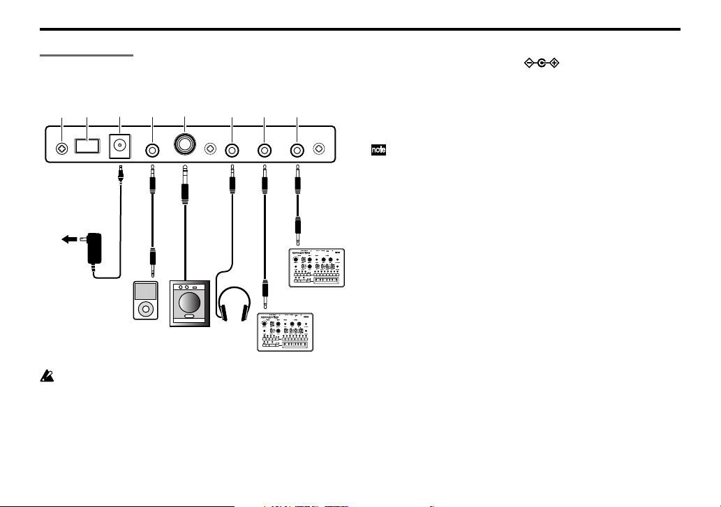
The following illustration shows an example of typical connections.
Connect your equipment as appropriate for your needs.
1
82
to AC outlet
AC adapter
(sold separately)
Audio player
You must turn off the power before connecting anything. Careless
usage may damage your speaker system or cause other malfunctions.
34
Monitor speaker
(with amplifier)
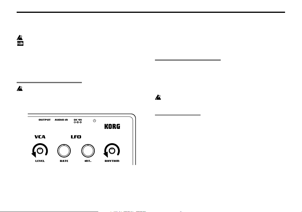
1. Power switch
This turns the power on/off. To turn the power off, press and hold
the switch.
5
Head-
phones
67
SYNC OUT
monotribe
SYNC IN
monotribe
2. DC 9V jack
Connect the optional AC adapter here.
3. AUDIO IN jack
An external audio source connected to the AUDIO IN jack will be
mixed with the VCO (p.11) and sent through the VCF (p.11) and VCA
(p.11). You can use this to expand the monotribe’s sonic possibilities,
or use it as an effect processor for a separate audio source.
A signal input in stereo will be mixed to mono.
4. OUTPUT jack
Connect the monotribe’s OUTPUT jack to the INPUT jack of your
mixer or powered monitor speakers. The output signal is monaural,
but the jack will accept either monaural phone plugs or stereo phone
plugs (unbalanced).
5. HEADPHONES jack
Connect your headphones (stereo mini-plug) here.
6. SYNC OUT jack
This jack outputs a 5V pulse of 15ms at the beginning of each step.
You can use this to synchronize another monotribe or other compatible equipment such as an analog sequencer to this monotribe unit. A
Global menu setting (p.16) lets you specify the polarity of the pulse.
7. SYNC IN jack
If the SYNC IN jack is connected, the internal step clock will be ignored, and the sequencer will proceed through its steps according to
the pulses that are input to this jack. You can use this jack to synchronize the monotribe’s steps with pulses that are output from another
monotribe unit, your analog sequencer or the audio output of a DAW.
A Global menu setting (p.16) lets you specify the polarity of the pulses that are detected.
8
Page 9
Owner’s manual
8. Grounding Screw
Use this screw to ground the unit. To do so, loosen the screw and
attach a grounding wire.
Do not use the unit if the screw is removed.
Depending on how the unit is connected to other devices, you may
feel a slight electrical stimulation if a soft part of your skin touches
a connected microphone or the metal part of the unit.
This is caused by a very weak current that is harmless to humans.
If this bothers you, use this grounding screw to ground the unit
externally.
Turning the power on
Before you turn on the monotribe, you must turn off the power of
your powered monitors or any other external output system.
1. Turn the monotribe’s LEVEL knob (p.11) and RHYTHM knob (p.15)
all the way to the left.
2. Press the monotribe’s power switch (p.8) to turn the power on.
The step LEDs (p.15) will indicate the remaining amount of battery power.
3. Lower the volume controls of your powered monitors or external
output system, and then turn their power on.
4. Turn the monotribe’s LEVEL knob and RHYTHM knob clockwise
to an appropriate level.
5. Adjust the volume of your external output system.
Turning the power off
1. Lower the volume of your powered monitors or external output
system, and turn their power off.
2. Turn the monotribe’s LEVEL knob (p.11) and RHYTHM knob (p.15)
all the way to the left, and hold down the power switch until any
lit LEDs have gone dark.
Never turn off the monotribe while global data (p.16) is being written. Doing so may damage the internal data.
Auto power-off
The monotribe has an auto power-off function. This function automatically turns the power off after approximately four hours have
passed since the monotribe last produced sound.
Disabling the auto power-off function
If desired, you can disable the auto power-off function.
For details on this procedure, refer to the Global menu (p.16).
9
Page 10
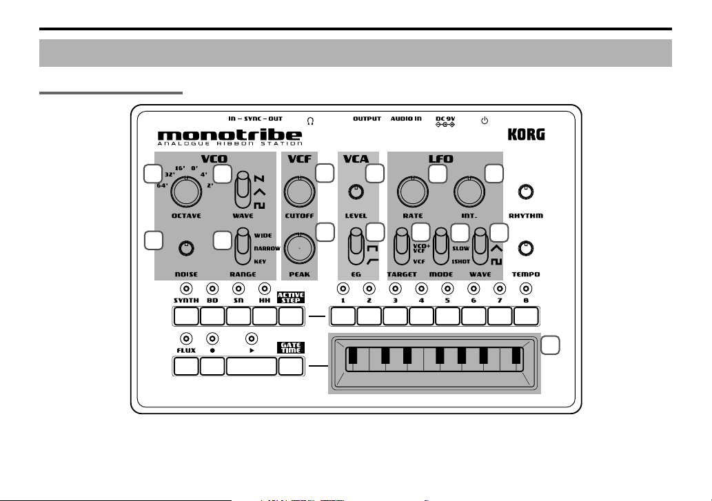
Synthesizer section
Panel description and functions
10
1
3
2
4
5
6
7
8
9
11
12
10
13
14
Page 11

Owner’s manual
VCO (Voltage Controlled Oscillator)
The oscillator generates the waveform that’s the basis of the sound: a
sawtooth wave, triangle wave, or square wave. The noise generator
produces white noise. If an external audio source is connected to the
AUDIO IN jack, it will be mixed with the VCO’s output. The VCO
generates a waveform at a pitch that’s determined by the position
being touched on the ribbon keyboard or by performance data that
you’ve recorded as a sequence. In addition, the LFO can also apply
time-varying changes to the pitch.
1. OCTAVE selector
This specifies the VCO pitch in steps of an octave. With the ”64’” setting, the pitch range of the ribbon keyboard will be A0–D2.
2. WAVE select switch
This selects the VCO waveform: sawtooth, triangle, or square.
(Sawtooth wave)
(Triangle wave)
(Square wave)
3. NOISE knob
This knob adjusts the level of white noise that’s mixed with the VCO
output.
4. RANGE select switch
This specifies the ribbon keyboard’s playing mode.
WIDE The pitch range will be extended to approximately
six times that of the NARROW setting; pitch change
will be continuous. The OCTAVE selector will be
ignored.
NARROW The pitch will change continuously according to the
printed ribbon keyboard.
KEY The pitch will change in chromatic steps according
to the printed ribbon keyboard.
VCF (Voltage Controlled Filter)
The filter modifies the timbre (tonal character) by boosting or cutting
specific frequency regions of the sound produced by the oscillator.
The monotribe uses the traditional 12 dB/oct low-pass filter (LPF)
that was also used on the Korg MS-20. The character of the sound will
change significantly depending on the settings of this filter. In addition, you can use the LFO to modulate the filter’s cutoff frequency
over time.
5. CUTOFF knob
This adjusts the cutoff frequency of the VCF, affecting the brightness
of the sound.
Turning the knob toward the left will darken the sound, and turning
the knob toward the right will brighten the sound.
6. PEAK knob
This adjusts the resonance of the VCF, adding emphasis to the cutoff
frequency.
VCA (Voltage Controlled Amplifier)
The amp varies the volume of the sound. You can use the EG to make
the volume change over time.
7. LEVEL knob
This adjusts the volume.
11
Page 12
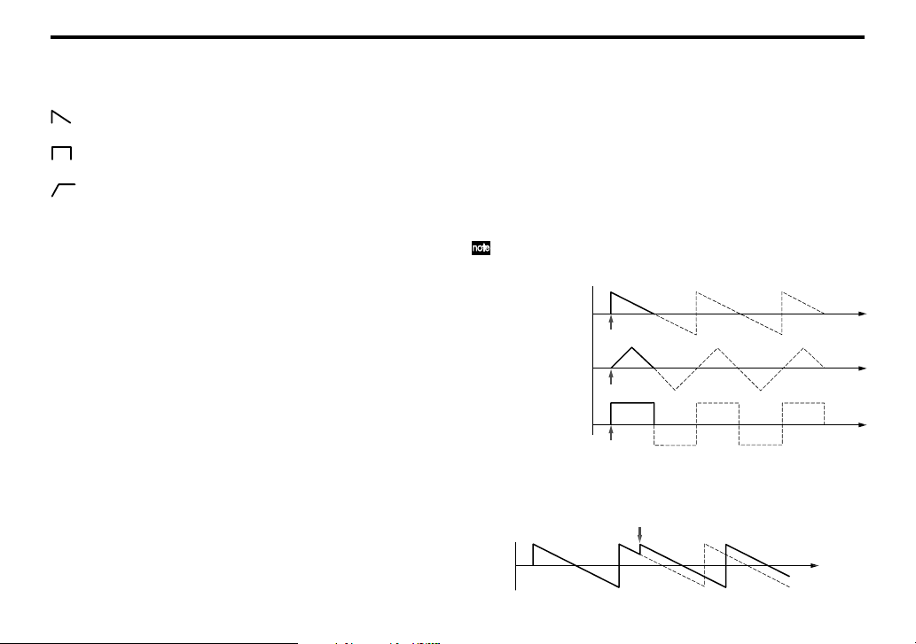
8. EG select switch
Note-on
Note-on
Note-on
A note played with 1SHOT
Sawtooth wave
Tr iangle wave
Square wave
This lets you choose one of three modulation waveforms for the EG
that’s applied to the VCA.
(DECAY) The volume will start at maximum the instant the
(GATE) The volume will remain at maximum while the note
(ATTACK) The volume will begin increasing the instant the
note is sounded, and will then decay.
is played.
note is sounded, and will remain at maximum while
the note is played.
LFO (Low Frequency Oscillator)
The LFO applies cyclical changes to the parameters that determine
the sound. You have three choices to specify which parameters will
be modulated. Since the modulation rate can be adjusted over a broad
range, you can use this to create everything from vibrato to sound
effects. You can also use 1SHOT mode to make the LFO behave like
an EG.
9. RATE knob
This adjusts the speed of modulation. Turning the knob toward the
right produces faster modulation.
10. INT. knob
This adjusts the intensity (depth) of modulation. If you turn the knob
all the way to the left, no modulation will be applied.
11. TARGET select switch
This specifies what will be affected by LFO modulation.
VCO The VCO pitch will change.
VCO+VCF The VCO pitch and the VCF cutoff frequency will
12
change.
VCF The VCF cutoff frequency will change.
12. MODE select switch
This switches the range of the modulation rate, or changes how modulation is applied.
FAST The modulation rate will have a range of approxi-
mately 1Hz to 5kHz.
SLOW The modulation rate will have a range of approxi-
mately 0.05Hz to 18Hz.
1SHOT When the note begins, the first half-cycle of modu-
lation will be applied, and then the LFO will stop.
KEY SYNC is applied if you select FAST or 1SHOT.
About KEY SYNC
Key Sync is a function that resets the phase of the LFO waveform
when a note is played.
Note-an
Page 13

Owner’s manual
13. WAVE select switch
This selects the modulation waveform: sawtooth wave, triangle wave,
or square wave. (p.11)
Keyboard
14. Ribbon keyboard
Touch this with your finger to play sounds.
Sequencer section
The monotribe contains an eight-step sequencer that controls the synthesizer and drum sound generator.
1
2
3
476 8
11
10
5
9
12
13
Page 14

Basic controls
1. PART LEDs
These will light-up when you press a PART button to select a part.
2. PART buttons
Press these buttons to select the part to be edited.
SYNTH button
Press this button when you want to edit the SYNTH (synthesizer) part. The SYNTH part LED will light-up when you press the
button.
BD button
Press this button when you want to edit the BD (bass drum) part.
The BD part LED will light-up when you press the button.
SN button
Press this button when you want to edit the SN (snare drum)
part. The SN part LED will light-up when you press the button.
HH button
Press this button when you want to edit the HH (hi-hat) part.
The HH part LED will light-up when you press the button.
The part LEDs will blink when the batteries run low. For details,
refer to “Battery level indication” (p.7).
3. ACTIVE STEP button
Use this button to turn each step of the sequence on (enabled) or off
(disabled).
While this button is pressed, the LED of each enabled step will lightup. To turn a step on/off, hold down the ACTIVE STEP button and
press the desired step button. Steps that are turned off are disabled
and will be skipped during playback and recording.
When you turn on the power, all steps are turned on.
It’s not possible to turn all steps off at the same time.
14
4. PLAY button
Press this button to play or stop the sequence. Playback always starts
from the beginning of the sequence. The PLAY LED will be lit during
playback.
5. TEMPO knob
This knob sets the speed of the sequencer.
The range of this knob can be changed in the Global menu (p.16).
With the NARROW setting, you can make detailed adjustments to
the tempo in a range of 60–180BPM. With the WIDE setting, you can
adjust the tempo in a range of 10–600BPM.
The TEMPO knob is disabled if the SYNC IN jack is connected.
The numerical tempo values listed above refer to when each step
is considered a 16th note.
Synthesizer sequence controls
6. FLUX button
This button turns FLUX mode on/off.
ON The sequence of the synth part will be recorded and
played back as continuous data.
OFF One note will play back for each step.
Tu rning this off might result in unexpected playback pitches depending on the performance’s timing.
Page 15

Owner’s manual
Pitch
FLUX ON
FLUX OFF
Step 1 Step 2 Step 3 Step 4 Step 5
7. REC button
Pressing this button during playback will put the monotribe in record
mode; the REC LED will light-up. When you play the ribbon keyboard, the data of your performance will be recorded.
Pressing this button while stopped will put the monotribe in recordready mode; the REC LED will blink. In this state, pressing the PLAY
button to start playback will activate record mode.
To exit record mode or record-ready mode, press the REC button once
again to make the REC LED go dark.
8. GATE TIME button
By holding down this button and using the ribbon keyboard while
a sequence plays back, you can change the gate time (duration) of the
synth part’s notes; the change in gate time corresponds to the position where you touch the ribbon keyboard.
The gate time will be the minimum value (1.4%) at the far left of the
ribbon keyboard, and the maximum value (100%) at the far right. By
performing this operation in REC mode, the gate time for each step
can be recorded in the sequence to occur during playback.
Note-on
1.4% 50% 100%
Step 1 Step 2 Step 3
9. STEP LEDs
These LEDs will light-up or go dark when you press the corresponding step button. While a sequence plays back, the LEDs will blink to
indicate the current step.
10. STEP buttons
These buttons turn each step on/off.
ON
OFF The step will not be played and its step LED will
If you record on a step that is turned off, it will automatically turn
on. If you do this, any data previously recorded in that step will be
erased.
The step will be played and its step LED will light-up.
not light-up.
Drum sound generator sequence controls
11. RHYTHM knob
This knob adjusts the volume of the drum sound generator.
12. STEP buttons
These buttons turn each step of the selected drum part (BD, SN, HH)
on/off.
ON
OFF The step will not be played and its step LED will
If you turn on a step button while holding down a part button, the
part will sound half way through the step. This applies to each of the
8 step buttons, effectively providing 16 steps for the rhythm sequence.
Step
Part button
released
held down
The step will be played and its step LED will light-up.
not light-up.
15
Page 16

Saving a sequence
When the sequencer is not playing back and the monotribe is not producing sound, hold down the REC button until the REC LED stops
blinking and goes dark.
The saved sequence will be loaded at the next power-up. To change
this, you’ll need to adjust the settings located in the Global menu (p.16).
Never turn off the power while data is being saved. Doing so may
destroy the internal data.
The saved settings are remembered even when the power is off.
Global menu
Here you can adjust various settings for the monotribe. These settings are assigned to step buttons 1–7 (see the table below).
Step button 1 Auto power-off
LED Unlit Auto power-off is disabled.
* LED Lit Auto power-off is enabled.
Step button 2 Battery type selection
* LED Unlit The monotribe is optimized for alkaline batteries.
LED Lit The monotribe is optimized for nickel-metal hy-
dride batteries.
Step button 3 SYNC OUT polarity
* LED Unlit The output will rise at the beginning of each step.
LED Lit The output will fall at the beginning of each step.
Step button 4 SYNC IN polarity
* LED Unlit The step will advance when the input signal rises.
LED Lit The step will advance when the input signal falls.
Step button 5 Sequence settings at start-up
LED Unlit The initial sequence will be loaded at power-on.
LED Blinking The saved sequence will be loaded at power-on.
* LED Lit The demo sequence will be loaded at power-on.
Step button 6 Drum preview
LED Unlit Nothing will sound when you press one of the drum
sound generator part buttons.
* LED Lit The corresponding drum sound will be heard when
you press one of the drum sound generator part
buttons.
Step button 7 TEMPO knob range
LED Unlit The TEMPO range will be narrow.
* LED Lit The TEMPO range will be wide.
* indicates the factory default setting.
Setting procedure
Press the corresponding step button to make the setting.
1. While holding down the ACTIVE STEP button and the GATE TIME
button, turn the power on. The monotribe will enter Global Menu
mode.
2. Press the step button for the setting that you want to change. The
LED will indicate the setting.
16
Page 17

Owner’s manual
3. When you’ve finished adjusting settings, press the REC button to
save the changes and start up the monotribe in its normal state.
If you decide to cancel, press the FLUX button. The changes will
be discarded, and the monotribe will start up in its normal state.
Never turn off the power while data is being saved. Doing so may
destroy the internal data.
The saved settings are remembered even when the power is off.
Specifications
Operating temperature 0–+40°C (non-condensing conditions)
Keyboard Ribbon keyboard
Sound generator Analog synthesis
Drum 3 parts, discrete analog
Sequencer 8 steps
Connectors
AUDIO IN jack ø3.5mm stereo mini-phone jack
OUTPUT jack ø6.3mm stereo phone jack (unbalanced)
HEADPHONES jack ø3.5mm stereo mini-phone jack
SYNC IN jack ø3.5mm monaural mini-phone jack
Maximum input level 20V
SYNC OUT jack ø3.5mm monaural mini-phone jack
Output level 5V
Power supply “AA/LR6” alkaline battery x6 or AA
1VCO (saw, triangle, square), noise generator, 1VCF (12dB/oct LPF), 1VCA, 1LFO
nickel-metal hydride battery x6
Optional AC adapter (DC9V
)
Battery life approximately 14 hours (when using al-
Dimensions (W x D x H)
Weight 735g/1.62 lbs. (excluding batteries)
Included items Six AA alkaline batteries for verifying op-
* Specifications and appearance are subject to change without notice
for improvement.
kaline batteries)
207 x 145 x 70mm/8.15 x 5.71 x 2.76 inches
eration, owner’s manual
17
Page 18
Sommaire
Précautions....................................................................19
Caractéristiques principales ........................................... 20
Structure du générateur de sons.....................................20
Les trois éléments du son (hauteur, timbre et volume) ...................... 20
Schéma de principe ........................................................................................... 21
Préparations .................................................................. 22
Installation des piles ......................................................................................... 22
Alimentation par adaptateur secteur ........................................................ 22
Indication de la charge des piles ................................................................. 22
Connexions ........................................................................................................... 23
Mise sous tension ............................................................................................... 24
Mise hors tension ............................................................................................... 24
Mise hors tension automatique ................................................................... 24
Description et fonctions .................................................. 25
Section synthétiseur ......................................................................................... 25
Section séquenceur ........................................................................................... 28
Menu Global ................................................................. 31
Procédure de réglage ....................................................................................... 32
Fiche technique .............................................................. 32
Merci d’avoir choisi le station analogique à ruban monotribe
de Korg.
Afin de pouvoir exploiter au mieux toutes les possibilités offertes par l’instrument, veuillez lire attentivement ce manuel.
Page 19
Manuel d’utilisation
Précautions
Emplacement
L’utilisation de cet instrument dans les endroits suivants peut en entraîner le
mauvais fonctionnement.
• En plein soleil
• Endroits très chauds ou très humides
• Endroits sales ou fort poussiéreux
• Endroits soumis à de fortes vibrations
• A proximité de champs magnétiques
Alimentation
Branchez l’adaptateur secteur mentionné à une prise secteur de tension
appropriée. Evitez de brancher l’adaptateur à une prise de courant dont la
tension ne correspond pas à celle pour laquelle l’appareil est conçu.
Interférences avec d’autres appareils électriques
Les postes de radio et de télévision situés à proximité peuvent par conséquent
souffrir d’interférences à la réception. Veuillez dès lors faire fonctionner cet
appareil à une distance raisonnable de postes de radio et de télévision.
Maniement
Pour éviter de les endommager, manipulez les commandes et les boutons de cet
instrument avec soin.
Entretien
Lorsque l’instrument se salit, nettoyez-le avec un chiffon propre et sec. Ne vous
servez pas d’agents de nettoyage liquides tels que du benzène ou du diluant,
voire des produits inflammables.
Conservez ce manuel
Après avoir lu ce manuel, veuillez le conserver soigneusement pour toute
référence ultérieure.
Evitez toute intrusion d’objets ou de liquide
Ne placez jamais de récipient contenant du liquide près de l’instrument. Si le
liquide se renverse ou coule, il risque de provoquer des dommages, un courtcircuit ou une électrocution.
Veillez à ne pas laisser tomber des objets métalliques dans le boîtier (trombones,
par ex.). Si cela se produit, débranchez l’alimentation de la prise de courant et
contactez votre revendeur korg le plus proche ou la surface où vous avez acheté
l’instrument.
Note concernant les dispositions (Seulement EU)
Quand un symbole avec une poubelle barrée d’une croix apparait sur
le produit, le mode d’emploi, les piles ou le pack de piles, cela signifie
que ce produit, manuel ou piles doit être déposé chez un représentant
compétent, et non pas dans une poubelle ou toute autre déchetterie
conventionnelle. Disposer de cette manière, de prévenir les
dommages pour la santé humaine et les dommages potentiels pour
l'environnement. La bonne méthode d'élimination dépendra des lois et
règlements applicables dans votre localité, s’il vous plaît, contactez
votre organisme administratif pour plus de détails. Si la pile contient des
métaux lourds au-delà du seuil réglementé, un symbole chimique est affiché
en dessous du symbole de la poubelle barrée d’une croix sur la pile ou le
pack de piles.
REMARQUE IMPORTANTE POUR LES CLIENTS
Ce produit a été fabriqué suivant des spécifications sévères et des besoins
en tension applicables dans le pays où ce produit doit être utilisé. Si vous
avez acheté ce produit via l’internet, par vente par correspondance ou/et
vente par téléphone, vous devez vérifier que ce produit est bien utilisable
dans le pays où vous résidez.
AT TENTION: L’utilisation de ce produit dans un pays autre que celui pour
lequel il a été conçu peut être dangereuse et annulera la garantie du
fabricant ou du distributeur. Conservez bien votre récépissé qui est la preuve
de votre achat, faute de quoi votre produit ne risque de ne plus être couvert
par la garantie du fabricant ou du distributeur.
*Tous les noms de produits et de sociétés sont des marques commerciales ou
déposées de leur détenteur respectif.
19
Page 20

Caractéristiques principales
Synthèse analogique
Les VCO, VCF et VCA sont constitués de circuits analogiques. Avec
des opérations simples et le processus de création sonore propre aux
synthés analogiques, le monotribe vous permet de faire de la synthèse sonore de façon extrêmement flexible et intuitive. Le filtre (VCF)
propose le circuit du classique Korg MS-20.
Fonction d’accordage automatique
Quand il ne produit aucun son, le monotribe effectue un accordage
interne pour corriger toute déviation de hauteur due à des changements de température ou au temps qui passe. En dépit de l’oscillateur (VCO) analogique, le monotribe n’a pas besoin d’un entretien
régulier pour rester accordé: le monotribe fonctionne de façon fiable
dès sa mise sous tension.
Clavier ruban
Vous pouvez changer la plage du clavier ruban (WIDE/NARROW). Le clavier ruban vous permet aussi de jouer de façon chromatique comme sur un
clavier conventionnel et donc de jouer des mélodies avec des notes exactes.
Générateur de sons de batterie analogique
Le générateur de sons de batterie interne à trois parties utilise des
circuits analogiques distincts.
Séquenceur à 8 pas
Vous pouvez piloter la séquence en temps réel pour créer des boucles
avec les sons de batterie et la partie de synthé.
Mode FLUX
Ce mode permet d’enregistrer et de reproduire la partie de synthé
sans être limité par les pas. Il permet de créer des rythmes complexes
et des grooves uniques.
LFO multifonctionnel
Avec de larges plages de réglage pour les paramètres RATE et INTENSITY, vous pouvez aller du changement subtil à la modulation drasti-
20
que. En plus de sa fonction d’oscillateur basse fréquence, le LFO propose un mode 1SHOT qui le transforme en générateur d’enveloppe (EG).
Prise d’entrée externe
Cette prise vous permet de modifier le son de la partie de synthé en
ajoutant un signal audio externe au signal du VCO. Elle permet aussi d’utiliser le monotribe comme processeur d’effets pour source audio externe.
Haut-parleur interne
Le monotribe dispose d’un haut-parleur interne, ce qui vous permet
de l’écouter n’importe où.
Adaptateur secteur ou piles
Vous avez le choix entre une alimentation par piles quand vous êtes
sur le terrain ou par adaptateur secteur (vendu séparément) pour des
sessions plus longues.
Structure du générateur de sons
Comme le montre le schéma de principe (p. 21), le générateur de sons
du synthétiseur est constitué d’un oscillateur (VCO), d’un filtre (VCF)
et d’un amplificateur (VCA). Le synthé produit des sons quand vous
touchez le clavier ruban ou reproduisez des données de séquence. Le
générateur de sons de batterie dispose de trois parties: grosse caisse
(“bass drum”, BD), caisse claire (“snare”, SN) et charleston (“hi-hat”,
HH). Il est piloté par des données de séquence.
Les trois éléments du son (hauteur, timbre et volume)
Le son compte trois éléments fondamentaux: la hauteur, le timbre et
le volume. Comme les synthés analogiques classiques, le monotribe
dispose de sections VCO (oscillateur), VCF (filtre) et VCA (amplificateur) pour façonner ces trois éléments. Editez le VCO pour changer la
hauteur, le VCF pour changer le timbre et le VCA pour changer le
volume.
De plus, vous pouvez utiliser le générateur d’enveloppe (EG) et l’oscillateur
basse fréquence (LFO) pour modifier ces paramètres de façon dynamique.
Page 21

Schéma de principe
NOISE
Manuel d’utilisation
PITCH
Générateur
VCO
SLOW
FAST
RANGE
PITCH
de bruit
1SHOT
OCTAVE
KEY TRACK
RATE
AUDIO IN
LFO
INT.
SEQUENCER
CLAVIER RUBAN
CUTOFF
PEAK LEVEL
VCF VCA
CUTOFF
SYNC
VCO+VCF
VCF
VCO
TARGET
Commandes de pas
et de transport
EG
EG
batterie à
trois parties
TRIGGER
SYNC IN
SYNC OUT
AUDIO OUT
LEVEL
TEMPO
21
Page 22

Préparations
Installation des piles
Avant de remplacer les piles, coupez l’alimentation.
Extrayez toujours immédiatement les piles usées du monotribe. La
présence de piles usées dans l’instrument peut provoquer des dysfonctionnements (dus à une fuite du liquide des piles). Retirez également les piles si vous n’avez pas l’intention d’utiliser le monotribe
pendant une période prolongée.
Ne mélangez pas des piles partiellement utilisées avec des piles
neuves et ne mélangez pas différents types de piles.
1. Ouvrez le couvercle du compartiment à piles situé sur le panneau
arrière.
Alimentation par adaptateur secteur
Branchez l’adaptateur secteur disponible en option à la prise DC9V.
Coupez l’alimentation avant de brancher l’adaptateur secteur.
Utilisez exclusivement l’adaptateur secteur spécifié. Si vous utili-
sez un autre adaptateur secteur que le modèle spécifié, vous risquez de provoquer des dysfonctionnements.
Indication de la charge des piles
Au démarrage
Les témoins (numérotés) de pas (p. 30) indiquent la charge résiduelle
des piles. Si tous les témoins s’allument, les piles sont complètement
chargées. Moins il y a de témoins allumés, plus les piles sont usées.
Quand un adaptateur secteur est branché, l’indication de charge
résiduelle des piles n’est pas correcte.
Vous pouvez utiliser des piles alcalines ou au nickel-hydrure métallique. Pour une détection fiable de la charge résiduelle des piles,
utilisez le menu Global (p. 31) pour préciser le type de piles utilisées.
2. Insérez six piles AA en veillant à respecter la polarité correcte
(l’orientation +/–). Utilisez des piles alcalines ou au nickel-hydrure
métallique.
3. Refermez le couvercle du compartiment à piles.
La pile fournie permet de vérifier que le produit fonctionne correctement. Sa durée de vie peut être plus brève que d’habitude.
22
En cours de fonctionnement
Si les piles s’épuisent, le monotribe vous avertit en faisant clignoter
les quatre témoins de parties (p. 29) simultanément.
Si les piles sont complètement épuisées, le témoin numéroté 1 clignote puis l’alimentation de l’appareil est coupée.
Il est impossible d’arrêter les signaux vous avertissant que les piles sont presque épuisées mais vous pouvez continuer à utiliser le
monotribe jusqu’à épuisement complet.
Les données non sauvegardées sont perdues. Sauvegardez donc
vos données si nécessaire (p.31).
Page 23

Manuel d’utilisation
Connexions
L’illustration suivante montre un exemple typique de connexions.
Branchez le matériel répondant à vos besoins.
1
82
A une prise
de courant
Adaptateur secteur
(vendu séparément)
Lecteur audio
Coupez l’alimentation avant d’effectuer la moindre connexion. Une
mauvaise utilisation risque d’endommager vos enceintes ou d’entraîner d’autres dysfonctionnements.
34
Enceinte active
1. Interrupteur d’alimentation
Il met l’appareil sous/hors tension. Pour couper l’alimentation, maintenez le bouton enfoncé.
5
Casque
67
SYNC OUT
monotribe
SYNC IN
monotribe
2. Prise DC 9V
Branchez l’adaptateur secteur disponible en option ici.
3. Prise AUDIO IN
Une source audio externe peut être branchée à la prise AUDIO IN
pour être mélangée avec le signal du VCO (p. 26) avant d’être envoyée au VCF (p. 26) et au VCA (p. 26). Cela vous permet d’étendre
les possibilités de création sonore du monotribe ou d’utiliser ce dernier comme processeur d’effet pour une source audio.
Un signal d’entrée stéréo est mixé en un signal mono.
4. Prise OUTPUT
Branchez la prise OUTPUT du monotribe à l’entrée (INPUT) de votre
console de mixage ou de vos enceintes actives. Le signal de sortie est
mono mais la prise accepte des fiches jack mono ou stéréo (asymétrique).
5. Prise HEADPHONES
Vous pouvez y brancher un casque (mini-jack stéréo).
6. Prise SYNC OUT
Cette prise émet une pulsation de 5V durant 15ms au début de chaque pas. Vous pouvez l’utiliser pour synchroniser un autre monotribe ou un autre dispositif compatible, comme un séquenceur analogique, avec votre monotribe. Un réglage du menu Global (p. 31) vous
permet de spécifier la polarité de la pulsation.
7. Prise SYNC IN
Si vous avez branché un dispositif à la prise SYNC IN, l’horloge de
pas interne est ignorée et le séquenceur produit ses pas en suivant les
pulsations reçues à cette prise. Cette prise permet de synchroniser les
pas de votre monotribe avec des pulsations émises par un autre monotribe, un séquenceur analogique ou la sortie audio d’une station de
travail audio numérique (DAW). Un réglage du menu Global (p. 31)
vous permet de spécifier la polarité des pulsations détectées.
23
Page 24

8. Vis de terre
Utilisez cette vis pour relier l’appareil à la terre. Pour cela, desserrez
la vis et fixez un fil de mise à la terre.
N’utilisez pas l’appareil si cette vis a été retirée.
Selon la façon dont cet appareil est branché à d’autres appareils,
vous pouvez sentir une infime stimulation électrique quand vous
touchez un micro branché ou une partie métallique de l’appareil.
Ce phénomène est dû au passage d’un courant très faible, absolument inoffensif pour les êtres humains. Si cela vous dérange néanmoins, utilisez la vis de terre pour relier l’appareil à une terre externe.
Mise sous tension
Avant de mettre le monotribe sous tension, coupez l’alimentation
des enceintes actives ou de tout autre système d’amplification externe.
1. Tournez les commandes LEVEL (p. 26) et RHYTHM (p. 30) du
monotribe à bout de course vers la gauche.
2. Appuyez sur l’interrupteur du monotribe (p. 23) pour le mettre
sous tension. Les témoins (numérotés) de pas (p. 30) indiquent la
charge résiduelle des piles.
24
3. Diminuez le volume de vos enceintes actives ou de tout autre sys-
tème d’amplification externe et mettez-le(s) sous tension.
4. Tournez les commandes LEVEL et RHYTHM du monotribe vers
la droite jusqu’à un niveau adéquat.
5. Réglez le volume sur votre système d’amplification externe.
Mise hors tension
1. Diminuez le volume de vos enceintes actives ou de tout autre sys-
tème d’amplification externe et mettez-le(s) hors tension.
2. Tournez les commandes LEVEL (p. 26) et RHYTHM (p. 30) du
monotribe à bout de course vers la gauche et maintenez l’interrupteur enfoncé jusqu’à ce que tous les témoins s’éteignent.
Ne mettez jamais le monotribe hors tension quand il sauvegarde
des données globales (p. 31). Cela risquerait d’endommager les
données internes.
Mise hors tension automatique
Le monotribe propose une fonction de coupure d’alimentation automatique. L’alimentation est automatiquement coupée si le monotribe
ne produit aucun son durant environ 4 heures.
Désactiver la coupure automatique d’alimentation
Vous pouvez désactiver cette fonction de coupure automatique d’alimentation.
Pour savoir comment procéder, voyez le menu Global (p. 31).
Page 25

Section synthétiseur
Manuel d’utilisation
Description et fonctions
1
3
2
4
5
6
7
8
9
11
12
10
13
14
25
Page 26

VCO (‘Voltage Controlled Oscillator’)
L’oscillateur génère la forme d’onde constituant la base du son: une
onde en dents de scie, triangulaire ou carrée. Le générateur de bruit
produit du bruit blanc. Si une source audio externe est branchée à la
prise AUDIO IN, son signal est mixé avec le signal de sortie du VCO.
Le VCO génère une forme d’onde à une hauteur déterminée par l’endroit touché sur le clavier ruban ou par des données de jeu enregistrées sous forme de séquence. De plus, le LFO peut créer des changements de hauteur variant dans le temps.
1. Sélecteur OCTAVE
Il détermine la hauteur du VCO par octaves. Avec le réglage “64”, la
plage de hauteur du clavier ruban est de la0~ré2.
2. Sélecteur WAVE
Il sélectionne la forme d’onde du VCO: en dents de scie, triangulaire
ou carrée.
(Onde en dents de scie)
(Onde triangulaire)
(Onde carrée)
WIDE La plage de hauteur du clavier est environ six fois
plus large qu’avec le réglage “NARROW”. Le changement de hauteur est continu. Le réglage du sélecteur OCTAVE est ignoré.
NARROW La hauteur change de façon continue en fonction
du clavier imprimé sur le ruban.
KEY La hauteur change par pas chromatiques en fonc-
tion du clavier imprimé sur le ruban.
VCF (‘Voltage Controlled Filter’)
Le filtre modifie le timbre en accentuant ou en atténuant certaines
bandes de fréquences du son produit par l’oscillateur. Le monotribe
utilise un filtre passe-bas traditionnel (LPF) de 12dB/oct, également
utilisé sur le Korg MS-20. Les réglages de ce filtre exercent une influence considérable sur le timbre du son. De plus, vous pouvez utiliser le LFO pour moduler la fréquence de coupure du filtre dans le
temps.
5. Commande CUTOFF
Elle règle la fréquence de coupure du filtre VCF et modifie le timbre
du son.
Tournez cette commande à gauche pour adoucir le son ou tournez-la
à droite pour rendre le son plus brillant.
6. Commande PEAK
Elle règle la résonance du VCF et souligne la fréquence du filtre.
3. Commande NOISE
Cette commande règle le niveau du bruit blanc mixé avec le signal de
sortie du VCO.
4. Sélecteur RANGE
Il détermine la plage du clavier ruban.
26
VCA (‘Voltage Controlled Amplifier’)
L’amplificateur détermine le volume du son. Vous pouvez modifier
le volume dans le temps avec le générateur d’enveloppe (EG).
7. Commande LEVEL
Elle règle le volume.
Page 27

Manuel d’utilisation
Note activée
Note activée
Note activée
Une note jouée avec ‘1SHOT’
Onde en dents de scie
Onde triangulaire
Onde carrée
8. Sélecteur EG
Il vous permet de choisir une des trois formes d’onde du générateur
d’enveloppe (EG) modulant le VCA.
(DECAY) Le volume démarre au maximum dès que la note
(GATE) Le volume reste au maximum tant que la note est
(ATTACK) Le volume augmente dès que la note est produite
est produite puis chute.
maintenue.
puis reste au maximum tant que la note est maintenue.
LFO (‘Low Frequency Oscillator’)
Le LFO applique des changements cycliques aux paramètres façonnant le son. Vous avez plusieurs possibilités pour définir les paramètres à moduler. Comme la vitesse de modulation dispose d’une large
plage de réglage, vous pouvez vous servir de ce paramètre pour créer
des effets allant du vibrato aux effets spéciaux. Vous pouvez aussi
utiliser le mode 1SHOT pour que le LFO se comporte comme un générateur d’enveloppe (EG).
9. Commande RATE
Règle la vitesse de modulation. Tournez la commande vers la droite
pour accélérer la modulation.
10. Commande INT.
Règle l’intensité de la modulation. Si vous tournez la commande à
fond à gauche, aucune modulation n’est appliquée.
11. Sélecteur TARGET
Ce sélecteur détermine la cible de la modulation du LFO.
VCO La hauteur du VCO change.
VCO+VCF La hauteur du VCO et la fréquence de coupure du
VCF changent.
VCF La fréquence de coupure du VCF change.
12. Sélecteur MODE
Change la plage de vitesse de modulation ou la façon dont la modulation est appliquée.
FAST La plage de réglage de la vitesse de modulation est
d’environ 1Hz~5kHz.
SLOW La plage de réglage de la vitesse de modulation est
d’environ 0,05Hz~18Hz.
1SHOT Quand la note démarre, le premier demi-cycle de
modulation est appliqué puis le LFO s’arrête.
“KEY SYNC” si vous avez sélectionné “FAST” ou “1SHOT”.
KEY SYNC
La fonction “Key Sync” initialise la forme d’onde du LFO quand une
note est produite.
Note activée
27
Page 28

13. Sélecteur WAVE
Sélectionne la forme d’onde de modulation: onde en dents de scie,
triangulaire ou carrée. (p. 26)
Clavier
14. Clavier ruban
Touchez ce clavier du doigt pour produire des sons.
Section séquenceur
Le monotribe contient un séquenceur à 8 pas pilotant le synthétiseur et le générateur de sons de batterie.
11
5
28
1
2
3
10
9
12
476 8
Page 29

Manuel d’utilisation
Contrôleurs de base
1. Témoins de parties
Ces témoins s’allument quand vous appuyez sur un bouton de partie
pour sélectionner une partie.
2. Boutons de partie
Appuyez sur un de ces boutons pour sélectionner la partie à éditer.
Bouton SYNTH
Appuyez sur ce bouton pour éditer la partie de synthétiseur
(SYNTH). Le témoin de la partie SYNTH s’allume quand vous
actionnez le bouton.
Bouton BD
Appuyez sur ce bouton pour éditer la partie de grosse caisse (BD:
bass drum). Le témoin de la partie BD s’allume quand vous actionnez le bouton.
Bouton SN
Appuyez sur ce bouton pour éditer la partie de caisse claire (SN:
snare). Le témoin de la partie SN s’allume quand vous actionnez
le bouton.
Bouton HH
Appuyez sur ce bouton pour éditer la partie de charleston (HH:
hi-hat). Le témoin de la partie HH s’allume quand vous actionnez le bouton.
Les témoins des parties se mettent à clignoter quand les piles sont
pratiquement épuisées. Voyez la section “Indication de la charge
des piles” (p. 22).
3. Bouton ACTIVE STEP
Ce bouton permet d’activer ou de couper chaque pas de la séquence.
Tant que vous appuyez sur ce bouton, le témoin de chaque pas activé
s’allume. Pour activer ou couper un pas, maintenez le bouton ACTIVE STEP enfoncé et appuyez sur le bouton du pas en question. Les
pas coupés sont ignorés durant la reproduction et l’enregistrement.
A la mise sous tension, tous les pas sont activés.
Il est impossible de couper tous les pas simultanément.
4. Bouton PLAY
Appuyez sur ce bouton pour reproduire ou arrêter la séquence. La
reproduction démarre toujours au début de la séquence. Le témoin
PLAY est allumé durant la reproduction.
5. Commande TEMPO
Cette commande règle la vitesse du séquenceur.
La plage de réglage de cette commande peut être changée dans le
menu Global (p. 31).
Avec une plage étroite (60~180BPM), vous pouvez effectuer un réglage précis du tempo. Avec le réglage large, vous pouvez régler le tempo sur la plage 10~600BPM.
La commande TEMPO est désactivée si un dispositif externe est
branché à la prise SYNC IN.
Les valeurs de tempo numériques indiquées ci-dessus correspondent à des pas d’une double croche.
Commandes de séquence du synthétiseur
6. Bouton FLUX
Ce bouton active et coupe le mode FLUX.
Activé La séquence de la partie de synthé est enregistrée
et reproduite sous forme de données continues.
29
Page 30

Coupé Une note est reproduite par pas.
Step1 Step2 Step3
1,4% 50% 100%
Note activée
La désactivation de ce mode peut produire des hauteurs inattendues en fonction du timing du jeu.
Hauteur
“FLUX” activé
“FLUX” coupé
Pas 1 Pas 2 Pas 3 Pas 4 Pas 5
7. Bouton REC
Appuyez sur ce bouton pour faire passer le monotribe en mode d’enregistrement (le témoin REC s’allume). Quand vous jouez sur le clavier ruban, les données de votre jeu sont enregistrées.
Une pression sur ce bouton à l’arrêt fait passer le monotribe en attente d’enregistrement (le témoin REC clignote). Dans cet état, il suffit
d’appuyer sur le bouton PLAY pour passer en mode d’enregistrement.
Pour quitter le mode d’enregistrement ou d’attente d’enregistrement,
appuyez à nouveau sur le bouton REC (le témoin REC s’éteint).
8. Bouton GATE TIME
En maintenant ce bouton enfoncé et en utilisant le clavier ruban durant la reproduction d’une séquence, vous pouvez changer la durée
(“Gate Time”) des notes de la partie de synthé. L’ampleur du changement de la durée des notes dépend de la position où vous avez touché le clavier ruban.
Vous obtenez la valeur “Gate Time” minimum (1,4%) en touchant l’extrémité gauche du clavier et la valeur maximum (100%) en touchant
l’extrémité droite. Si vous effectuez cette opération en mode d’enregistrement, la valeur “Gate Time” de chaque pas peut être enregistrée
dans la séquence (et reproduite ensuite).
30
9. Témoins de pas
Ces témoins s’allument ou s’éteignent quand vous appuyez sur le
bouton de pas correspondant. Durant la reproduction d’une séquence, les témoins clignotent pour indiquer le pas en vigueur.
10. Boutons de pas
Ces boutons activent/coupent les différents pas.
Activé
Coupé Le pas n’est pas reproduit et le témoin correspon-
Si vous enregistrez sur un pas qui est coupé, il est automatiquement activé. Dans ce cas, les données enregistrées au préalable
pour ce pas sont effacées.
Le pas est reproduit et le témoin correspondant à ce
pas s’allume.
dant à ce pas ne s’allume pas.
Commandes de séquence du générateur de sons
de batterie
11. Commande RHYTHM
Cette commande règle le volume du générateur de sons de batterie.
12. Boutons de pas
Ces boutons activent/coupent les différents pas de la partie de batterie sélectionnée (BD, SN, HH).
Activé
Le pas est reproduit et le témoin correspondant à ce
pas s’allume.
Page 31

Manuel d’utilisation
Coupé Le pas n’est pas reproduit et le témoin correspon-
Si vous activez un bouton de pas tout en maintenant un bouton de
partie enfoncé, cette partie est audible à la moitié du pas. Cette fonction est disponible pour les 8 boutons de pas, ce qui vous permet de
disposer en réalité de 16 pas pour la séquence de batterie.
pas
Bouton
de partie
relâché
enfoncé
dant à ce pas ne s’allume pas.
Sauvegarder une séquence
Quand le séquenceur n’est pas en mode de reproduction et quand le
monotribe ne produit aucun son, maintenez le bouton REC enfoncé
jusqu’à ce que le témoin REC cesse de clignoter et s’éteigne.
La séquence sauvegardée sera chargée lors de la prochaine mise sous
tension. Vous pouvez changer la séquence chargée lors de la mise sous
tension dans le menu Global (p.31).
Ne coupez jamais l’alimentation quand l’appareil sauvegarde des
donnees. Vous risqueriez de detruire les donnees internes.
Les réglages sauvegardés sont conservés même quand l’alimentation est coupée.
Menu Global
Vous pouvez effectuer divers réglages concernant le fonctionnement
du monotribe. Ces réglages sont assignés aux boutons de pas 1~7
(voyez ci-dessous).
Bouton de pas 1 Mise hors tension automatique
Témoin éteint La mise hors tension automatique est désactivée.
*Témoin allumé La mise hors tension automatique est activée.
Bouton de pas 2 Sélection du type de piles
*Témoin éteint Le monotribe est prêt pour des piles alcalines.
Témoin allumé Le monotribe est prêt pour des piles au nickel-
Bouton de pas 3 Polarité ‘SYNC OUT’
*Témoin éteint Le signal de sortie croît au début de chaque pas.
Témoin allumé Le signal de sortie décroît au début de chaque
Bouton de pas 4 Polarité ‘SYNC IN’
*Témoin éteint Le pas avance quand le signal d’entrée croît.
Témoin allumé Le pas avance quand le signal d’entrée décroît.
Bouton de pas 5 Réglages de séquence au démarrage
Témoin éteint La séquence initiale est chargée à la mise sous
Témoin clignotant
*Témoin allumé La séquence de démo est chargée à la mise sous
Bouton de pas 6 Ecoute de la batterie
Témoin éteint Vous n’entendez rien quand vous appuyez sur
*Témoin allumé Vous entendez le son de batterie correspondant
hydrure métallique.
pas.
tension.
La séquence sauvegardée est chargée à la mise
sous tension.
tension.
un des boutons de parties de batterie.
quand vous appuyez sur un des boutons de parties de batterie.
31
Page 32

Bouton de pas 7 Plage de la commande TEMPO
Témoin éteint La plage de réglage du TEMPO est étroite.
*Témoin allumé La plage de réglage du TEMPO est large.
* Indique le réglage d’usine par défaut.
Procédure de réglage
Appuyez sur le bouton de pas correspondant pour effectuer le réglage.
1. En maintenant les boutons ACTIVE STEP et GATE TIME enfon-
cés, mettez l’appareil sous tension. Le monotribe passe en mode
de menu Global.
2. Appuyez sur le bouton de pas correspondant au réglage à effec-
tuer. Le témoin indique le réglage.
3. Quand vous avez fini vos réglages, appuyez sur le bouton REC
pour sauvegarder vos changements et redémarrer le monotribe
dans son état normal. Pour annuler l’opération, appuyez sur le
bouton FLUX. Les changements sont annulés et le monotribe
redémarre dans son état normal.
Ne coupez jamais l’alimentation quand l’appareil sauvegarde des
donnees. Vous risqueriez de detruire les donnees internes.
Les réglages sauvegardés sont conservés même quand l’alimentation est coupée.
32
Fiche technique
Te mpérature de fonctionnement
Clavier Clavier ruban
Générateur de sons Synthèse analogique
Batterie 3 parties, circuits analogiques dis-
Séquenceur 8 pas
Prises
Prise AUDIO IN Mini-jack stéréo ø3,5mm
Prise OUTPUT Jack stéréo ø6,3mm (asymétrique)
Prise HEADPHONES Mini-jack stéréo ø3,5mm
Prise SYNC IN Mini-jack mono ø3,5mm
Niveau d’entrée maximum 20V
Prise SYNC OUT Mini-jack mono ø3,5mm
Niveau de sortie 5V
Alimentation Piles AA/LR6 alcalines x6 ou piles
Autonomie des piles environ 14 heures (avec des piles al-
Dimensions (L x P x H) 207 x 145 x 70mm
Poids 735g (sans piles)
Accessoires fournis Six piles alcalines AA permettant de
* Les caractéristiques et l’aspect du produit sont susceptibles d’être
modifiés sans avis préalable en vue d’une amélioration.
0~+40°C (sans condensation)
1 VCO (onde en dents de scie, triangulaire, carrée), Générateur de bruit,
1 VCF (filtre passe-bas 12dB/oct), 1
VCA, 1 LFO
tincts
AA au nickel-hydrure métallique x6,
Adaptateur secteur en option (DC9V
)
calines)
vérifier le fonctionnement, Manuel
d’utilisation
Page 33

Inhaltsübersicht
Vorsichtsmaßnahmen.....................................................34
Die wichtigsten Funktionen ............................................35
Aufbau der Klangerzeugung .......................................... 35
Die drei Klangaspekte (Tonhöhe, Klangfarbe, Lautstärke) ................ 35
Blockschaltbild .................................................................................................... 36
Vorbereitung ................................................................. 37
Einlegen der Batterien ..................................................................................... 37
Verwendung eines Netzteils .......................................................................... 37
Anzeige der Batteriespannung ..................................................................... 37
Anschlüsse ............................................................................................................ 38
Einschalten ............................................................................................................ 39
Ausschalten .......................................................................................................... 39
Energiesparfunktion ......................................................................................... 39
Bedienelemente auf der Frontplatte ................................ 40
Synthesizer-Sektion ........................................................................................... 40
Sequenzersektion .............................................................................................. 43
Globale Funktionen .......................................................46
Einstellverfahren ................................................................................................. 47
Technische Daten ...........................................................47
Vielen Dank für Ihre Entscheidung zu einem monotribe analogen Bandstation von Korg.
Bitte lesen Sie sich diese Anleitung vollständig durch, um bei
der Bedienung alles richtig zu machen.
Page 34

Vorsichtsmaßnahmen
Aufstellungsort
Vermeiden Sie das Aufstellen des Geräts an Orten, an denen
• es direkter Sonneneinstrahlung ausgesetzt ist;
• hohe Feuchtigkeit oder Extremtemperaturen auftreten können;
• Staub oder Schmutz in großen Mengen vorhanden sind;
• das Gerät Erschütterungen ausgesetzt sein kann.
• in der Nähe eines Magnetfeldes.
Stromversorgung
Schließen Sie das optionale Netzteil nur an eine geeignete Steckdose an.
Verbinden Sie es niemals mit einer Steckdose einer anderen Spannung.
Störeinflüsse auf andere Elektrogeräte
Dieser kann bei in der Nähe aufgestellten Rund-funkempfängern oder
Fernsehgeräten Empfangsstörungen hervorrufen. Betreiben Sie solche Geräte
nur in einem geeigneten Abstand von diesem Erzeugnis.
Bedienung
Vermeiden Sie bei der Bedienung von Schaltern und Reglern unangemessenen
Kraftaufwand.
Reinigung
Bei auftretender Verschmutzung können Sie das Gehäuse mit einem trockenen,
sauberen Tuch abwischen. Verwenden Sie keinerlei Flüssigreiniger wie
beispielsweise Reinigungsbenzin, Verdünnungs- oder Spülmittel. Verwenden Sie
niemals brennbare Reiniger.
Bedienungsanleitung
Bewahren Sie diese Bedienungsanleitung gut auf, falls Sie sie später noch
einmal benötigen.
Flüssigkeiten und Fremdkörper
Stellen Sie niemals Behältnisse mit Flüssigkeiten in der Nähe des Geräts auf.
Wenn Flüssigkeit in das Gerät gelangt, können Beschädigung des Geräts, Feuer
oder ein elek-trischer Schlag die Folge sein.
Beachten Sie, daß keinerlei Fremdkörper in das Gerät gelangen. Sollte ein
Fremdkörper in das Gerät gelangt sein, so trennen Sie es sofort vom Netz.
Wenden Sie sich dann an Ihren KORG-Fachhändler.
Hinweis zur Entsorgung (Nur EU)
Wenn Sie das Symbol mit der „durchgekreuzten Mülltonne“ auf Ihrem
Produkt, der dazugehörigen Bedienungsanleitung, der Batterie oder
dem Batteriefach sehen, müssen Sie das Produkt in der
vorgeschriebenen Art und Weise entsorgen. Dies bedeutet, dass
dieses Produkt mit elektrischen und elektronischen Komponenten
nicht mit dem normalen Hausmüll entsorgt werden darf. Für Produkte
dieser Art existiert ein separates, gesetzlich festgelegtes
Entsorgungssystem. Gebrauchte elektrische und elektronische
Geräte müssen separat entsorgt werden, um ein umweltgerechtes Recycling
sicherzustellen. Diese Produkte müssen bei benannten Sammelstellen
abgegeben werden. Die Entsorgung ist für den Endverbraucher kostenfrei!
Bitte erkundigen sie sich bei ihrer zuständigen Behörde, wo sie diese
Produkte zur fachgerechten Entsorgung abgeben können. Falls ihr Produkt
mit Batterien oder Akkumulatoren ausgerüstet ist, müssen sie diese vor
Abgabe des Produktes entfernen und separat entsorgen (siehe oben). Die
Abgabe dieses Produktes bei einer zuständigen Stelle hilft ihnen, dass das
Produkt umweltgerecht entsorgt wird. Damit leisten sie persönlich einen nicht
unerheblichen Beitrag zum Schutz der Umwelt und der menschlichen
Gesundheit vor möglichen negativen Effekten durch unsachgemäße
Entsorgung von Müll. Batterien oder Akkus, die Schadstoffe enthalten, sind
auch mit dem Symbol einer durchgekreuzten Mülltonne gekennzeichnet. In
der Nähe zum Mülltonnensymbol befindet sich die chemische Bezeichnung
des Schadstoffes.
Cd oder NiCd steht für Cadmium, Pb für Blei und Hg für Quecksilber.
Dieses Produkt wurde unter strenger Beachtung von Spezifikationen und
Spannungsanforderungen hergestellt, die im Bestimmungsland gelten. Wenn
Sie dieses Produkt über das Internet, per Postversand und/oder mit
telefonischer Bestellung gekauft haben, müssen Sie bestätigen, dass dieses
Produkt für Ihr Wohngebiet ausgelegt ist.
WARNUNG: Verwendung dieses Produkts in einem anderen Land als dem,
für das es bestimmt ist, verwendet wird, kann gefährlich sein und die
Garantie des Herstellers oder Importeurs hinfällig lassen werden. Bitte
bewahren Sie diese Quittung als Kaufbeleg auf, da andernfalls das Produkt
von der Garantie des Herstellers oder Importeurs ausgeschlossen werden
kann.
*Alle Produkt- und Firmennamen sind Warenzeichen oder eingetragene
Warenzeichen der betreffenden Eigentümer.
WICHTIGER HINWEIS FÜR KUNDEN
34
Page 35

Bedienungsanleitung
Die wichtigsten Funktionen
Analog-Synthese
Der VCO, VCF und VCA beruhen auf analogen Schaltungen. Dank
einer intuitiven Bedienung geht die Klangprogrammierung so schnell
wie auf einem Analog-Synthesizer vonstatten: Mit dem monotribe ist
endlich wieder flexibles und „aus dem Bauch ‘raus“-Arbeiten angesagt. Der VCF enthält übrigens dieselbe Filterschaltung wie der unvergessene Korg MS-20.
Automatische Stimmfunktion
Wann immer der monotribe keine Noten ausgeben muss, korrigiert
er selbsttätig seine Stimmung, um temperatur- oder altersbedingtes
„Driften“ zu vermeiden. Obwohl der VCO des monotribe analog ist,
benötigt er für seine Stimmstabilität keine regelmäßige Wartung. Außerdem ist der monotribe unmittelbar nach dem Einschalten einsatzbereit.
Bandtastatur
Der Tonumfang der Bandtastatur kann geändert werden (WIDE/
NARROW). Selbstverständlich kann sie auch chromatisch (d.h. wie
eine herkömmliche Tastatur) gespielt werden, so dass man Melodien
spielen kann.
Analoge Schlagzeugklangerzeugung
Das Gerät enthält eine separate analoge Schlagzeugklangerzeugung
mit drei Parts.
Step-Sequenzer mit 8 Schritten
Die Sequenz kann nicht nur die Schlagzeug-Sounds und den Synthesizerpart ansprechen, sondern auch in Echtzeit geändert werden.
FLUX-Modus
In diesem Modus kann die Synthesizersequenz unabhängig von den
Schritten des Step-Sequenzers aufgezeichnet und abgespielt werden.
Damit lassen sich ausgefuchste Grooves und Sequenzfiguren mit einem einzigartigen Rhythmus erzeugen.
Flexibel einsetzbarer LFO
Dank zahlreicher „RATE“- und „INTENSITY“-Einstellungsmöglichkeiten ist die Modulation so dezent bzw. brachial wie man selbst möchte.
Außer den herkömmlichen LFO-Funktionen steht ein 1SHOT-Modus
zur Verfügung, in dem sich der LFO wie eine Hüllkurve (EG) verhält.
Externer Eingang
Das hier anliegende Signal kann mit dem vom VCO erzeugten Signal
zu einem neuartigen Synthi-Sound kombiniert werden. Der monotribe kann aber auch als Effektprozessor für externe Audiosignale missbraucht werden.
Interner Lautsprecher
Da der monotribe einen Lautsprecher enthält, kann man an jedem
gewünschten Ort experimentieren und musizieren.
Netzteil und Batteriespeisung
Das Gerät kann sowohl mit Batterien als auch mit einem optionalen
Netzteil betrieben werden.
Aufbau der Klangerzeugung
Wie das Blockschaltbild (S. 36) zeigt, enthält der Synthesizerteil einen
Oszillator (VCO), ein Filter (VCF) und einen Verstärker (VCA). Um
den Synthesizer anzusteuern, müssen Sie entweder die Bandtastatur
drücken oder den Sequenzer starten. Der Schlagzeugteil umfasst drei
Parts – Bassdrum (BD), Snare (SN) und HiHat (HH). Diese werden
von der Sequenz angesteuert.
Die drei Klangaspekte (Tonhöhe, Klangfarbe, Lautstärke)
Alle Klänge beruhen auf drei Basisaspekten: Tonhöhe, Klangfarbe
(rund oder hell) und Lautstärke. Wie seine analogen Vorfahren bietet
der monotribe eine VCO-, VCF- und VCA-Sektion, mit denen sich
diese Aspekte beeinflussen lassen. Mit dem VCO legen Sie die Tonhöhe fest, mit dem VCF die Klangfarbe und mit dem VCA die Lautstärke. Diese Aspekte können mit einer Hüllkurve (EG) und einem
Niederfrequenzoszillator (LFO) dynamisch beeinflusst werden.
35
Page 36

Blockschaltbild
NOISE
36
PITCH
GENERATOR
VCO
SLOW
FAST
RANGE
PITCH
RAUSCH-
1SHOT
OCTAVE
KEY TRACK
RATE
AUDIO IN
LFO
INT.
SEQUENCER
BANDTASTATUR
CUTOFF
PEAK LEVEL
VCF VCA
CUTOFF
SYNC
VCO+VCF
VCF
VCO
TARGET
SCHRITT-,
TRANSPORTTASTER
EG
EG
SCHLAGZEUGKLANGER-
ZEUGUNG
MIT DREI PARTS
TRIGGER
SYNC IN
SYNC OUT
AUDIO OUT
LEVEL
TEMPO
Page 37

Vorbereitung
Einlegen der Batterien
Vor dem Auswechseln der Batterien müssen Sie das Gerät unbedingt ausschalten.
Erschöpfte Batterien müssen so schnell wie möglich aus dem
monotribe entfernt werden, weil es sonst zu Betriebsstörungen (z.B.
durch Auslaufen der Batterieflüssigkeit) kommen kann. Entfernen
Sie die Batterien außerdem, wenn Sie den monotribe längere Zeit
nicht verwenden möchten.
Wechseln Sie immer alle Batterien aus und verwenden Sie nur jeweils Batterien desselben Typs.
1. Entfernen Sie den Batteriefachdeckel an der Unterseite.
2. Legen Sie sechs AA-Batterien unter Einhaltung der richtigen Po-
larität (+/–-Pol) ein. Verwenden Sie nur Alkali- oder Ni-MH-Batterien.
3. Schließen Sie das Batteriefach wieder.
Die beiliegende Batterie ist ausschließlich für Testzwecke gedacht.
Daher hat sie eine kürzere Lebensdauer als andere Batterien.
Verwendung eines Netzteils
Schließen Sie ein optionales AC-Netzteil an die DC9V-Buchse an.
Bedienungsanleitung
Vor dem Anschließen des Netzteils müssen Sie das Gerät ausschalten.
Verwenden Sie nur das ausdrücklich erwähnte Netzteil. Ein beliebiges anderes Netzteil könnte nämlich Funktionsstörungen hervorrufen.
Anzeige der Batteriespannung
Beim Einschalten
Die Schritt-Dioden (S. 45) zeigen die Restlaufzeit der Batterien an.
Wenn alle Dioden leuchten, sind die Batterien noch komplett geladen. Je weniger Dioden leuchten, desto schwächer ist die Batteriespannung.
Solange ein Netzteil angeschlossen ist, wird die Restlaufzeit der
Batterien nicht zuverlässig angezeigt.
Es können wahlweise Alkali- oder Ni-MH-Batterien verwendet wer-
Anm.
den. Die Batteriespannung kann nur zuverlässig gemessen werden, wenn Sie angeben, welchen Batterietyp Sie eingelegt haben
(S. 46).
Während des Betriebs
Wenn die Batterien nahezu erschöpft sind, beginnen die Dioden der
vier Parts (S. 44) zu blinken.
Wenn die Batterien komplett erschöpft sind, blinkt die Diode von
Schritt 1 kurz. Anschließend schaltet sich das Gerät aus.
Dieses warnende Blinken kann man zwar nicht abstellen, allerdings
Anm.
können Sie den monotribe noch so lange verwenden, bis die Batterien komplett erschöpft sind.
Bedenken Sie, dass bis dahin nicht gespeicherte Daten dann verloren gehen. Speichern Sie Ihre Einstellungen also regelmäßig (S.
46).
37
Page 38

Anschlüsse
Nachstehend wird ein typisches Anschlussbeispiel gezeigt. Selbstverständlich können Sie sich auf die für Sie relevanten Geräte und Anschlüsse beschränken.
1
82
Zu einer Steckdose
Netzteil
(Sonderzubehör)
Schalten Sie das Gerät vor Herstellen oder Lösen jedweder Anschlüsse aus. Andernfalls könnten Sie die Lautsprecher beschädigen oder Betriebsstörungen verursachen.
34
Audio-Player
Aktivbox
(mit eigenem Verstärker)
Kopfhörer
1. Netzschalter
Hiermit schalten Sie das Gerät ein und aus. Zum Ein- und Ausschalten müssen Sie den Taster eine Weile gedrückt halten.
38
5
67
SYNC OUT
monotribe
SYNC IN
monotribe
2. DC 9V-Buchse
Schließen Sie hier ein optionales Netzteil an.
3. AUDIO IN-Buchse
Die mit der AUDIO IN-Buchse verbundene Signalquelle wird mit dem
VCO-Signal (S. 41) kombiniert und an den VCF (S. 41) sowie den VCA
(S. 41) angelegt. Das können Sie zum Erweitern des Wellenformangebots Ihres monotribe nutzen. Umgekehrt kann er mit diesem System
auch als Effektprozessor für eine Audioquelle fungieren.ce.
In Stereo angelegte Signale werden zu einem Mono-Signal
Anm.
zusammengefasst.
4. OUTPUT-Buchse
Verbinden Sie die OUTPUT-Buchse des monotribe mit einem Eingang
Ihres Mischpults oder einer Aktivbox. Das Ausgangssignal ist zwar
mono, aber man kann im Notfall auch ein (unsymmetrisches) Stereokabel an diese Buchse anschließen.
5. HEADPHONES-Buchse
Hier kann ein Kopfhörer (mit Miniklinke) angeschlossen werden.
6. SYNC OUT-Buchse
Diese Buchse gibt am Beginn eines jeden Schritts einen 15ms langen
5V-Impuls aus. Dieser kann zum Synchronisieren eines zweiten monotribe oder eines kompatiblen Geräts (z.B. ein Analog-Sequenzer)
genutzt werden. Mit einem globalen Menüparameter (S. 46) lässt sich
die Polarität des Impulses einstellen.
7. SYNC IN-Buchse
Wenn Sie einen Stecker an die SYNC IN-Buchse anschließen, wird der
Taktgeber des internen Sequenzers ignoriert. Stattdessen werden die
Schritte bei Empfang von Impulsen eines externen Geräts angefahren.
Diese Buchse können Sie zum Synchronisieren des monotribe-Sequenzers zu Impulsen eines zweiten monotribe, eines Analog-Sequenzers oder
der Audio-Ausgabe Ihrer DAW nutzen. Mit einem globalen Menüparameter (S. 46) lässt sich die Polarität der erwarteten Impulse einstellen.
Page 39

Bedienungsanleitung
8. Masseschraube
Über diese Schraube kann das Gerät geerdet werden. Lösen Sie die
Schraube und schließen Sie ein Erdungskabel an.
Verwenden Sie das Gerät niemals, nachdem Sie die Schraube entfernt haben.
Bei der Verbindung dieses Geräts mit bestimmten anderen Gerä-
Anm.
ten spüren Sie eventuell einen leichten Stromschlag, wenn Sie mit
einer weichen Hautpartie ein angeschlossenes Mikrofon oder eine
Metallpartie des Gerätes berühren.
Das liegt an einer geringfügigen Strommenge, die für Menschen
völlig harmlos ist. Wenn Sie das aber als unangenehm empfinden,
können Sie das Gerät über diese Schraube erden.
Einschalten
Vor dem Einschalten des monotribe müssen Sie die externe Aktivbox bzw. Ihr Verstärkungssystem ausschalten.
1. Drehen Sie den LEVEL- (S. 41) und RHYTHM-Regler (S. 45) des
monotribe ganz nach links.
2. Drücken Sie den Netzschalter (S. 38), um den monotribe einzu-
schalten. Die Schritt-Dioden (S. 45) zeigen jetzt die Restlaufzeit
der Batterien an.
3. Stellen Sie die Lautstärke der Aktivbox bzw. des externen Verstär-
kers auf den Mindestwert und schalten Sie sie/ihn ein.
4. Drehen Sie den LEVEL- und RHYTHM-Regler des monotribe ganz
allmählich nach rechts.
5. Stellen Sie den Wiedergabepegel des Verstärkers usw. ein.
Ausschalten
1. Stellen Sie die Lautstärke der Aktivboxen bzw. des externen Ver-
stärkers auf den Mindestwert und schalten Sie sie/ihn aus.
2. Drehen Sie den LEVEL- (S. 41) und RHYTHM-Regler (S. 45) des
monotribe ganz nach links und halten Sie den Netzschalter so lange
gedrückt, bis alle Dioden erloschen sind.
Schalten Sie den monotribe niemals aus, solange noch globale
Daten gespeichert werden (S. 46). Sonst könnten Sie nämlich die
internen Daten beschädigen.
Energiesparfunktion
Der monotribe enthält eine Energiesparfunktion. Ungefähr 4 Stunden nach dem letzten Bedienvorgang bzw. nach Ausgabe des letzten
Signals schaltet sich der monotribe selbsttätig aus.
Deaktivieren der Energiesparfunktion
Bei Bedarf können Sie diese Energiesparfunktion deaktivieren.
Hinweise zur Arbeitsweise finden Sie auf S. 46.
39
Page 40

Bedienelemente auf der Frontplatte
Synthesizer-Sektion
40
1
3
2
4
5
6
7
8
9
11
12
10
13
14
Page 41

Bedienungsanleitung
VCO (Voltage Controlled Oscillator)
Der Oszillator erzeugt eine Wellenform, die den Grundcharakter des
Klangs vorgibt: Eine Sägzahn-, Dreieck- oder Rechteckwelle. Der
Rauschgenerator erzeugt weißes Rauschen. Wenn Sie an die AUDIO
IN-Buchse eine Signalquelle anschließen, wird deren Signal mit jenem des VCO gemischt. Die Tonhöhe der vom VCO erzeugten Wellenform richtet sich nach der Position, an der Sie die Bandtastatur
drücken bzw. nach den vom Sequenzer gespielten Noten. Bei Bedarf
lässt sich die Tonhöhe mit dem LFO variieren.
1. OCTAVE-Wahlschalter
Hiermit legen Sie die Basistonhöhe des VCO in Oktavschritten fest.
Die Einstellung „64’“ bedeutet, dass die Bandtastatur Noten im Bereich A0–D2 spielen kann.
2. WAVE-Wahlschalter
Hiermit wählen Sie die Wellenform des VCO: Sägezahn, Dreieck oder
Rechteck.
(Sägezahnwelle)
(Dreieckwelle)
(Rechteckwelle)
3. NOISE-Regler
Mit diesem Regler stellen Sie den Pegel des weißen Rauschens ein,
das am VCO-Ausgang hinzugefügt wird.
4. RANGE-Wahlschalter
Hiermit bestimmen Sie, wie die Bandtastatur gespielt werden kann.
WIDE Der Tonumfang ist etwa 6 Mal größer als bei Anwahl
von „NARROW“ und die Tonhöhe ändert sich stufenlos. Die „OCTAVE“-Einstellung wird ignoriert.
NARROW Die Tonhöhe ändert sich stufenlos, folgt aber der
Unterteilung der Bandtastatur.
KEY Die Tonhöhe ändert sich in chromatischen Schritten
– wie auf einer herkömmlichen Tastatur.
VCF (Voltage Controlled Filter)
Das Filter beeinflusst die Klangfarbe der vom Oszillator erzeugten
Wellenform. Hiermit kann man bestimmte Frequenzbereiche anheben oder abschwächen. Der monotribe enthält ein herkömmliches
12dB/Okt-Tiefpassfilter (LPF), das erstmals im Korg MS-20 zum Einsatz kam. Die Filtereinstellungen haben einen großen Einfluss auf die
Klangfarbe. Bei Bedarf kann die Filterfrequenz mit dem LFO periodisch moduliert werden.
5. CUTOFF-Regler
Hiermit stellen Sie die Filterfrequenz des VCF ein und machen den
Klang heller oder runder.
Normalerweise wird der Klang dumpfer, wenn Sie den Regler nach
links drehen und heller, wenn Sie ihn nach rechts drehen.
6. PEAK-Regler
Hiermit kann die Resonanz des VCF eingestellt werden. Damit lässt
sich die Filterfrequenz hervorheben.
VCA (Voltage Controlled Amplifier)
Der Verstärker bestimmt die Lautstärke des Sounds. Mit der Hüllkurve lassen sich dynamische Lautstärkevariationen erzielen.
7. LEVEL-Regler
Bestimmt die Lautstärke.
41
Page 42

8. EG-Wahlschalter
Note an
Note an
Note an
Eine im „1SHOT“-Modus gespielte Note.
Sägezahnwelle
Dreieckwelle
Rechteckwelle
Hiermit wählen Sie eine von 3 verfügbaren Hüllkurvengestalten, mit
denen der VCA bearbeitet werden kann.
(DECAY) Jede gespielte Note verwendet anfangs den Höchst-
(GATE) Die Lautstärke der gespielten Noten bleibt konstant.
(ATTACK) Jede gespielte Note schwillt allmählich an und ver-
pegel und wird dann allmählich leiser.
harrt dann beim Höchstpegel.
LFO (Low Frequency Oscillator)
Mit dem LFO können die gewählten Klangaspekte periodisch variiert („moduliert“) werden. Hier kann aus drei Möglichkeiten gewählt
werden. Da sich die Modulationsgeschwindigkeit sehr detailliert einstellen lässt, können Sie mit dem LFO alles zwischen Vibrato und
Klangeffekten erzeugen. Es gibt auch einen 1SHOT-Modus, in dem
sich der LFO wie eine Hüllkurve nutzen lässt.
9. RATE-Regler
Hiermit regeln Sie die Modulationsgeschwindigkeit. Drehen Sie den
Regler nach rechts, um eine höhere Geschwindigkeit zu wählen.
10. INT.-Regler
Hiermit bestimmen Sie die Modulationsintensität. Drehen Sie ihn ganz
nach links, um den Effekt auszuschalten.
11. TARGET-Wahlschalter
Hiermit bestimmen Sie, welchen Aspekt der LFO beeinflusst.
VCO Die Tonhöhe des VCO ändert sich.
VCO+VCF Die Tonhöhe des VCO und die Filterfrequenz des
VCF Die Filterfrequenz des VCF wird beeinflusst.
42
VCF werden beeinflusst.
12. MODE-Wahlschalter
Hiermit wählen Sie entweder die Modulationsgeschwindigkeit oder
das Modulationsverhalten.
FAST Die Modulationsgeschwindigkeit bewegt sich im
SLOW Die Modulationsgeschwindigkeit bewegt sich im
1SHOT Beim Einsatz einer Note wird die erste Hälfte der
Bei Anwahl von „FAST“ oder „1SHOT“ ist die „KEY SYNC“-Funkti-
Anm.
on aktiv.
Apropos ‘KEY SYNC’
„Key Sync“ ist eine Funktion, welche die Phase der LFO-Wellenform
am Beginn jeder Note zurückstellt.
Bereich 1Hz–5kHz.
Bereich 0.05Hz–18Hz.
Modulationswelle durchfahren. Danach hält der LFO
an.
Note-an
Page 43

Bedienungsanleitung
13. WAVE-Wahlschalter
Hiermit wählen Sie die Modulationswellenform: Sägzahn-, Dreieckoder Rechteckwelle. (S. 41)
Tastatur
14. Bandtastatur
Berühren Sie dieses Band mit einem Finger, um einen Klang zu erzeugen.
Sequenzersektion
Der monotribe enthält einen 8-Schritt Step-Sequenzer, der den Synthesizer und die Schlagzeugsektion ansteuert.
1
2
3
476 8
11
10
5
9
12
43
Page 44

Basisbedienelemente
1. Partdioden
Diese leuchten für alle Parts, die Sie aktivieren.
2. Parttaster
Mit diesen Tastern wählen Sie den Part, den Sie editieren möchten.
SYNTH-Taster
Drücken Sie diesen Taster, um den Synthesizer-Part (SYNTH) zu
editieren. Wenn Sie den Taster drücken, leuchtet die SYNTH-Diode.
BD-Taster
Drücken Sie diesen Taster, um den Bassdrum-Part (BD) zu editieren. Wenn Sie den Taster drücken, leuchtet die BD-Diode.
SN-Taster
Drücken Sie diesen Taster, um den Snare-Part (SN) zu editieren.
Wenn Sie den Taster drücken, leuchtet die SN-Diode.
HH-Taster
Drücken Sie diesen Taster, um den HiHat-Part (HH) zu editieren. Wenn Sie den Taster drücken, leuchtet die HH-Diode.
Wenn die Batterien fast erschöpft sind, beginnen die Partdioden
Anm.
zu blinken. Siehe auch „Anzeige der Batteriespannung“ (S. 37).
3. ACTIVE STEP-Taster
Hiermit können Sie die einzelnen Sequenzschritte ein- (aktiv) oder
ausschalten (nicht aktiv).
Solange Sie diesen Taster gedrückt halten, leuchten die Dioden der
momentan aktiven Schritte. Um einen Schritt zu ein-/auszuschalten,
müssen Sie den ACTIVE STEP-Taster gedrückt halten, während Sie
den betreffenden Schritt-Taster betätigen. Deaktivierte Schritte werden während der Wiedergabe und Aufnahme übersprungen.
Unmittelbar nach dem Einschalten des Geräts sind alle Schritte
Anm.
aktiv.
Es können niemals alle Schritte deaktiviert werden.
Anm.
44
4. PLAY-Taster
Drücken Sie diesen Taster, um die Sequenz zu starten und anzuhalten. Die Wiedergabe beginnt immer beim Anfang der Sequenz. Während der Wiedergabe leuchtet die PLAY-Diode.
5. TEMPO-Regler
Hiermit stellen Sie die Geschwindigkeit der Sequenz ein.
Der Einstellbereich dieses Reglers kann geändert werden (S. 46).
Bei Anwahl des begrenzten Bereichs lässt sich das Tempo im Bereich
60–180BPM einstellen. Im erweiterten Modus lautet der Einstellbereich 10–600BPM.
Wenn Sie etwas an die SYNC IN-Buchse anschließen, ist der TEMPO-Regler nicht mehr belegt.
Die oben erwähnten Tempowerte beziehen sich auf einen Takt mit
Anm.
Sechzehntelunterteilungen.
Sequenzbedienelemente für den Synthesizer
6. FLUX-Taster
Hiermit schalten Sie den FLUX-Modus ein und aus.
An Die Sequenz des Synthesizerparts wird als kontinuierlicher
Datenstrom aufgezeichnet und abgespielt.
Aus Pro Schritt wird nur jeweils eine Note ausgegeben.
Wenn Sie diesen Modus deaktivieren, kommt es eventuell zu über-
Anm.
raschenden Tonhöhesprüngen, die sich nach dem Timing richten.
Page 45

Bedienungsanleitung
Tonhöhe
FLUX an
FLUX aus
Schritt 1 Schritt 2 Schritt 3 Schritt 4 Schritt 5
7. REC-Taster
Wenn Sie während der Wiedergabe diesen Taster drücken, aktiviert
der monotribe den Aufnahmebetrieb (die REC-Diode leuchtet). Alles, was Sie auf der Bandtastatur spielen, wird dann aufgezeichnet.
Wenn Sie diesen Taster bei angehaltener Wiedergabe drücken, aktiviert der monotribe die Aufnahmebereitschaft (der REC-Taster blinkt).
Um die Aufnahme zu starten, müssen Sie den PLAY-Taster drücken.
Um den Aufnahmebetrieb oder die Aufnahmebereitschaft zu deaktivieren,
müssen Sie den REC-Taster erneut drücken (die REC-Diode erlischt dann).
8. GATE TIME-Taster
Halten Sie diesen Taster gedrückt, während Sie einen Finger über die
Bandtastatur bewegen, um die Dauer (Länge) der Synthesizernoten
zu ändern. Die Notendauer richtet sich nach der Fingerposition auf
der Bandtastatur. Der „Gate Time“-Wert kann im Bereich 1,4% (ganz
links auf der Tastatur) bis 100% (ganz rechts) geändert werden. Wenn
Sie dieses Verfahren während der Aufnahme verwenden, werden die
„Gate Time“-Änderungen ebenfalls aufgezeichnet.
Note an
1,4% 50% 100%
Schritt 1 Schritt 2 Schritt 3
9. Schrittdioden
Diese Dioden leuchten oder erlöschen, wenn Sie den zugehörigen
Schritt-Taster drücken. Während er Sequenzwiedergabe zeigen die
Dioden jeweils an, welcher Schritt gerade abgespielt wird.
10. Schritt-Taster
Hiermit können die Sequenzschritte aktiviert und deaktiviert werden.
An Der betreffende Schritt wird abgespielt (die Diode leuchtet).
Der betreffende Schritt wird nicht abgespielt (die Diode ist aus).
Ans
Wenn Sie etwas für einen momentan ausgeschalteten Schritt auf-
Anm.
zeichnen, wird er aktiviert. Die zuvor für jenen Schritt gepufferten
Daten werden dann allerdings gelöscht.
Sequenzbedienelemente für die Schlagzeugsektion
11. RHYTHM-Regler
Hiermit regeln Sie die Lautstärke der Schlagzeugsektion.
12. Schritt-Taster
Hiermit können die Sequenzschritte für den gewählten Schlagzeugpart (BD, SN, HH) aktiviert und deaktiviert werden.
An Der betreffende Schritt wird abgespielt (die Diode leuchtet).
Ans
Der betreffende Schritt wird nicht abgespielt (die Diode ist aus).
Wenn Sie einen Schritt-Taster gedrückt halten, während Sie einen
Parttaster drücken, erklingt jener Part erst in der zweiten Hälfte jenes
Schritts. Dieses System gilt für alle 8 Schritte, was also bedeutet, dass
die Rhythmussequenz eigentlich 16 Schritte bietet.
Schritt
Parttaster
Freigabe
Drücken
45
Page 46

Speichern einer Sequenz
Halten Sie die Sequenzerwiedergabe an und sorgen Sie dafür, dass
der monotribe kein Signal ausgibt. Halten Sie den REC-Taster so lange gedrückt, bis die REC-Diode erlischt.
Beim nächsten Einschalten wird diese Sequenz wieder geladen. Allerdings können beim Einschalten auch andere Daten geladen werden. Siehe S. 16.
Schalten Sie das Instrument niemals aus, solange Daten gespeichert werden. Sonst gehen die internen Daten namlich verloren.
Die Einstellungen werden beim Ausschalten gespeichert.
Anm.
Globale Funktionen
Hier können mehrere verborgene Funktionen des monotribe eingestellt werden. Die Parameter sind den Schritt-Tastern 1–7 zugeordnet
(siehe die Tabelle unten).
Schritt-Taster 1 Energiesparfunktion
Diode aus Die Energiesparfunktion ist nicht aktiv.
*
Diode leuchtet
Schritt-Taster 2 Angabe des Batterietyps
* Diode aus Der monotribe wurde für Alkalibatterien optimiert.
Diode leuchtet
Schritt-Taster 3 YNC OUT-Polarität
* Diode aus Das Ausgangssignal steigt am Beginn eines jeden
Diode leuchtet Das Ausgangssignal fällt am Beginn eines jeden
Die Energiesparfunktion ist aktiv.
Der monotribe wurde für Ni-MH-Batterien optimiert.
Schrittes.
Schrittes.
Schritt-Taster 4 SYNC IN-Polarität
* Diode aus Wenn das Eingangssignal ansteigt, wird der näch-
Diode leuchtet Wenn das Eingangssignal fällt, wird der nächste
Schritt-Taster 5 Sequenzereinstellungen beim Einschalten
Diode aus Beim nächsten Einschalten wird die Sequenz initia-
Diode blinkt Beim nächsten Einschalten wird die gespeicherte
*
Diode leuchtet
Schritt-Taster 6 Schlagzeugwiedergabe
Diode aus Bei Drücken eines Parttasters der Schlagzeugsekti-
*
Diode leuchtet
Schritt-Taster 7 Einstellbereich des TEMPO-Reglers
Diode aus Begrenzter TEMPO-Einstellbereich.
*
Diode leuchtet
* Vertritt die Werksvorgabe.
ste Schritt gewählt.
Schritt gewählt.
lisiert.
Sequenz geladen.
Beim nächsten Einschalten wird die Demosequenz
geladen.
on hören Sie nichts.
Bei Drücken eines Parttasters der Schlagzeugsekti-
on hören Sie den betreffenden Schlagzeugklang.
Maximaler TEMPO-Einstellbereich.
46
Page 47

Bedienungsanleitung
Einstellverfahren
Drücken Sie den Schritt-Taster der Funktion, deren Einstellung Sie
ändern möchten.
1. Halten Sie den ACTIVE STEP- und GATE TIME-Taster gedrückt,
während Sie das Gerät wieder einschalten. Damit rufen Sie den
Global-Modus des monotribe auf.
2. Drücken Sie den Schritt-Taster des änderungsbedürftigen Parameters. Seine Diode zeigt den gewählten Status an.
3. Wenn alles wunschgemäß eingestellt ist, drücken Sie den REC-
Taster, um die Einstellungen zu speichern und den monotribe
wieder im Normalbetrieb hochzufahren. Drücken Sie den FLUXTaster, um den Vorgang abzubrechen. Dann werden Ihre Änderungen gelöscht und der monotribe wechselt wieder in den Normalzustand.
Schalten Sie das Instrument niemals aus, solange Daten gespeichert werden. Sonst gehen die internen Daten namlich verloren.
Die Einstellungen werden beim Ausschalten gespeichert.
Anm.
Technische Daten
Betriebstemperatur 0–+40°C (ohne Kondensbildung)
Tastatur Bandtastatur
Klangerzeugung Analog-Synthese
1 VCO (Sägezahn, Dreieck, Rechteck),
Rauschgenerator, 1 VCF (12dB/Okt
LPF), 1 VCA, 1 LFO
Schlagzeug 3 Parts, separater Analog-Schaltkreis
Sequenzer 8 Schritte
Anschlüsse
AUDIO IN-Buchse Stereo-Miniklinkenbuchse (ø3,5mm)
OUTPUT-Buchse ø6,3mm-Stereoklinkenbuchse (unsym-
HEADPHONES-Buchse Stereo-Miniklinkenbuchse (ø3,5mm)
SYNC IN-Buchse Mono-Miniklinkenbuchse (ø3,5mm)
Maximaler Eingangspegel
SYNC OUT-Buchse Mono-Miniklinkenbuchse (ø3,5mm)
Ausgangspegel 5V
Stromversorgung AA/LR6-Alkalibatterie x6 oder AA Ni-
Batterielaufzeit ±14 Stunden (bei Verwendung von Al-
Abmessungen (B x T x H) 207 x 145 x 70mm
Gewicht 735g (ohne Batterien)
Lieferumfang 6 AA-Batterien für Testzwecke, Bedie-
* Änderungen der technischen Daten und des Designs ohne vorheri-
ge Ankündigung vorbehalten.
metrisch)
20V
MH-Batterie x6, Optionales AC-Netzteil
(DC9V
kali-Batterien)
nungsanleitung
)
47
Page 48

Índice
Precauciones ................................................................. 49
Características principales ............................................. 50
Cómo se estructura el generador de sonido ...................50
Los tres elementos del sonido (afinación, timbre y volumen) ......... 50
Diagrama de bloques ....................................................................................... 51
Primeros pasos ..............................................................52
IInstalar las baterías ........................................................................................... 52
Utilizar un adaptador de CA .......................................................................... 52
Indicación del nivel de batería...................................................................... 52
Conexiones ........................................................................................................... 53
Activar el equipo ................................................................................................ 54
Desactivar el equipo ......................................................................................... 54
Desactivación automática .............................................................................. 54
Descripción y funciones de los paneles........................... 55
Sección del sintetizador .................................................................................. 55
Sección del secuenciador ............................................................................... 58
Menú Global ................................................................. 61
Procedimiento de ajuste ................................................................................. 61
Especificaciones ............................................................. 62
Gracias por adquirir el estación de cinta analógico monotribe de
Korg.
Por favor, lea este manual atentamente y guárdelo para futuras
consultas.
Page 49

manual del usuario
Precauciones
Ubicación
El uso de la unidad en las siguientes ubicaciones puede dar como resultado un
mal funcionamiento:
• Expuesto a la luz directa del sol
• Zonas de extremada temperatura o humedad
• Zonas con exceso de suciedad o polvo
• Zonas con excesiva vibración
• Cercano a campos magnéticos
Fuente de alimentación
Por favor, conecte el adaptador de corriente designado a una toma de corriente
con el voltaje adecuado. No lo conecte a una toma de corriente con voltaje
diferente al indicado.
Interferencias con otros aparatos
Las radios y televisores situados cerca pueden experimentar interferencias en la
recepción. Opere este dispositivo a una distancia prudencial de radios y
televisores.
Manejo
Para evitar una rotura, no aplique excesiva fuerza a los conmutadores o
controles.
Cuidado
Si exterior se ensucia, límpiese con un trapo seco. No use líquidos limpiadores
como disolvente, ni compuestos inflamables.
Guarde este manual
Después de leer este manual, guárdelo para futuras consultas.
Mantenga los elementos externos alejados del equipo
Nunca coloque ningún recipiente con líquido cerca de este equipo, podría causar
un cortocircuito, fuero o descarga eléctrica. Cuide de que no caiga ningún objeto
metálico dentro del equipo.
Nota respecto a residuos y deshechos (solo UE)
Cuando aparezca el símbolo del cubo de basura tachado sobre un
producto, su manual de usuario, la batería, o el embalaje de
cualquiera de éstos, significa que cuando quiere tire dichos artículos
a la basura, ha de hacerlo en acuerdo con la normativa vigente de la
Unión Europea. No debe verter dichos artículos junto con la basura
de casa. Verter este producto de manera adecuada ayudará a evitar
daños a su salud pública y posibles daños al medioambiente. Cada
país tiene una normativa específica acerca de cómo verter productos
potencialmente tóxicos, por tanto le rogamos que se ponga en contacto con
su oficina o ministerio de medioambiente para más detalles. Si la batería
contiene metales pesados por encima del límite permitido, habrá un símbolo
de un material químico, debajo del símbolo del cubo de basura tachado.
NOTA IMPORTANTE PARA EL CONSUMIDOR
Este producto ha sido fabricado de acuerdo a estrictas especificaciones y
requerimientos de voltaje aplicables en el país para el cual está destinado. Si
ha comprado este producto por internet, a través de correo, y/o venta
telefónica, debe usted verificar que el uso de este producto está destinado al
país en el cual reside.
AVISO: El uso de este producto en un país distinto al cual está destinado
podría resultar peligroso y podría invalidar la garantía del fabricante o
distribuidor.
Por favor guarde su recibo como prueba de compra ya que de otro modo el
producto puede verse privado de la garantía del fabricante o distribuidor.
*Todos los nombres de productos y compañías son marcas comerciales o
marcas registradas de sus respectivos propietarios.
49
Page 50

Características principales
Síntesis analógica
El VCO, VCF y el VCA están construidos con una circuitería analógica.
Con un funcionamiento sencillo e intuitivo y con el proceso de creación de sonido característico de los sintetizadores analógicos, el monotribe le ofrece una síntesis flexible y que facilita enormemente la improvisación. El VCF incluye el circuito de filtro del Korg MS-20 clásico.
Función de autosintonización
Cuando no genera sonidos, el monotribe se autosintoniza internamente para corregir cualquier problema de afinación que pueda producirse debido a los cambios de temperatura o al desgaste. A pesar del
VCO analógico, el monotribe no requiere un mantenimiento regular
para permanecer sintonizado; el monotribe funcionará de manera fiable desde el mismo momento en que se active.
Teclado de cinta
Puede seleccionar el intervalo de afinación del teclado de cinta (WIDE/
NARROW). También se puede tocar cromáticamente como un teclado convencional, de modo que podrá reproducir melodías con una
afinación precisa.
Generador de sonido de percusión analógico
Das Gerät enthält eine separate analoge Schlagzeugklangerzeugung
mit drei Parts.
Secuenciador de ocho pasos
Puede controlar la secuencia a tiempo real para crear bucles mediante los sonidos de percusión y la parte de sintetizador.
Modo FLUX
Esto permite grabar la secuencia de la parte de sintetizador y reproducirla sin los límites de los pasos. Se trata de una excelente forma de crear
ritmos complicados y patrones de secuencia con ritmos únicos.
LFO multifunción
Una amplia gama de ajustes de RATE e INTENSITY permiten realizar
50
desde cambios sutiles hasta modulaciones radicales. Además de la función LFO convencional, incluye un modo 1SHOT que hace que el LFO
actúe como un generador de envolvente (EG).
Jack de entrada externo
P
ermite modificar el sonido de la parte de sintetizador mezclando una
fuente de audio externa con el VCO. También permite utilizar el monotribe como procesador de efectos para una fuente de audio externa.
Altavoz interno
El monotribe incluye un altavoz integrado para que pueda tocarlo en
cualquier parte.
Adaptador de CA o alimentación por baterías
Puede utilizar baterías si se encuentra de viaje o un adaptador de CA
(debe adquirirlo por separado) si debe utilizarlo durante periodos de
tiempo prolongados.
Cómo se estructura el generador de sonido
Tal como se muestra en el diagrama de bloques (p.51), el generador
de sonido del sintetizador está formado por un oscilador (VCO), un
filtro (VCF) y un amplificador (VCA). El sintetizador generará sonidos al tocar el teclado de cinta o al reproducir la información de secuencia. El generador de sonidos de percusión ofrece tres partes —
sonido de bombo (BD), de caja de percusión (SN) y de charles (HH)—
y lo reproduce la información de secuencia.
Los tres elementos del sonido (afinación, timbre y volumen)
El sonido tiene tres elementos básicos: la afinación, el timbre (carácter tonal) y el volumen. Igual que los sintetizadores analógicos clásicos, el monotribe ofrece las secciones VCO, VCF y VCA que permiten
controlar estos elementos. Edite el VCO para modificar la afinación,
el VCF para modificar el timbre y el VCA para modificar el volumen.
Además, puede utilizar el generador de envolvente (EG) y el oscilador de
frecuencia baja (LFO) para controlar los parámetros de forma dinámica.
Page 51

Diagrama de bloques
NOISE
manual del usuario
PITCH
GENERADOR
DE RUIDO
VCO
SLOW
FAST
RANGE
PITCH
1SHOT
OCTAVE
KEY TRACK
RATE
AUDIO IN
LFO
INT.
SEQUENCER
TECLADO DE CINTA
CUTOFF
PEAK LEVEL
VCF VCA
CUTOFF
SYNC
VCO+VCF
VCF
VCO
TARGET
PASO, CONTROLES
DE TRANSPORTE
EG
EG
PERCUSION DE
TRES PARTES
TRIGGER
SYNC IN
SYNC OUT
AUDIO OUT
LEVEL
TEMPO
51
Page 52

Primeros pasos
IInstalar las baterías
Desactive el equipo antes de sustituir las baterías.
Las baterías gastadas deben retirarse inmediatamente del
monotribe. Si no retira las baterías gastadas de su compartimento
puede provocar un funcionamiento incorrecto (las baterías pueden
tener pérdidas). También debería retirar las baterías si no tiene
previsto utilizar el monotribe durante un periodo de tiempo prolongado.
No mezcle las baterías medio gastadas con las nuevas, ni tampoco mezcle diferentes tipos de baterías.
1. Retire la tapa de las baterías del panel posterior.
Utilizar un adaptador de CA
Conecte el adaptador de CA opcional al jack DC9V.
Antes de conectar el adaptador de CA debe desactivar el equipo.
Debe utilizar únicamente el adaptador de CA específico. Si utiliza
cualquier otro adaptador de CA distinto al modelo indicado podría
provocar un funcionamiento incorrecto.
Indicación del nivel de batería
Al iniciar el equipo
Los LEDs parciales (p.60) indican la cantidad de batería restante. Si
todos los LEDs están iluminados significa que las baterías están al
máximo. A menor número de LEDs iluminados, menor será el nivel
de batería.
Si ha conectado un adaptador de CA, no se mostrará correctamente la cantidad de batería restante.
Pueden utilizarse tanto baterías alcalinas como de níquel-hidruro
metálico. Para poder detectar y mostrar correctamente la cantidad
de batería restante, debe utilizar el menú Global (p.61) para especificar el tipo de baterías que está utilizando.
2. Introduzca seis baterías AA, observando la polaridad correcta
(orientación +/–). Utilice baterías alcalinas o de níquel-hidruro
metálico.
3. Vuelva a colocar la tapa de las baterías.
Por favor, instale una nueva pila lo antes posible. La pila incluida se
proporciona para que usted pueda verificar que la unidad funciona
correctamente; su vida útil puede ser más corta de lo normal.
52
Durante el funcionamiento
Si el nivel de batería es bajo, el monotribe le avisará con el parpadeo
simultáneo de los cuatro LEDs (p.59).
Si las baterías se han agotado completamente, el LED parcial 1 parpadeará y el equipo se desactivará automáticamente.
No se puede detener el aviso de batería baja; no obstante, podrá
seguir utilizando el monotribe hasta que se hayan agotado las baterías completamente.
La información que no se haya guardado se perderá, de modo que
guárdela siempre que sea necesario (p.61).
Page 53

manual del usuario
Conexiones
La siguiente ilustración muestra un ejemplo de las conexiones típicas. Conecte el equipo de la forma que más le convenga.
1
82
a la toma de CA
Adaptador de CA
(debe adquirirlo
por separado)
Debe desactivar el equipo antes de realizar cualquier conexión.
Un uso poco cuidadoso puede provocar daños en el sistema de
altavoces o causar otro tipo de funcionamientos incorrectos.
34
Reproductor
de audio
Auriculares
Altavoz del monitor
(con amplificador)
1. Conmutador de alimentación
Permite activar o desactivar el equipo. Para activar el equipo, mantenga pulsado el conmutador.
5
67
SYNC OUT
monotribe
SYNC IN
monotribe
2. Jack DC 9V
Conecte el adaptador de CA opcional aquí.
3. Jack AUDIO IN
Se mezclará una fuente de audio externa conectada al jack AUDIO IN
con el VCO (p.56) y se enviará a través del VCF (p.56) y el VCA (p.56).
Puede utilizarlo para ampliar las posibilidades de sonido del monotribe o como procesador de efectos para una fuente de audio independiente.
Se mezclará una entrada de señal estéreo con una mono.
4. Jack OUTPUT
Conecte el jack OUTPUT del monotribe al jack INPUT del mezclador
o a los altavoces monitor autoalimentados. La señal de salida es monoaural, pero el jack aceptará conectores phone monoaurales o estéreo (no balanceados).
5. Jack HEADPHONES
Conecte sus auriculares (miniconector estéreo) aquí.
6. Jack SYNC OUT
Este jack envía un pulso de 5V y 15ms al principio de cada paso. Puede utilizarlo para sincronizar otro monotribe u otro equipo compatible, como un secuenciador analógico, con este equipo monotribe. Un
ajuste del menú Global (p.61) le permite especificar la polaridad del
pulso.
7. Jack SYNC IN
Si el jack SYNC IN está conectado, se ignorará el reloj interno y el
secuenciador continuará realizando sus pasos según los pulsos que
reciba este jack. Puede utilizar este jack para sincronizar los pasos del
monotribe con los pulsos enviados desde otro monotribe, desde el
secuenciador analógico o la salida de audio de un DAW. Un ajuste
del menú Global (p.61) le permite especificar la polaridad de los pulsos que se detectan.
53
Page 54

8. Tornillo de derivación a masa
Utilice este tornillo para derivar el equipo a masa. Para hacerlo, afloje
el tornillo y coloque un cable de masa.
No utilice la unidad si se ha retirado el tornillo.
Según la forma de conexión del equipo a otros dispositivos, es
posible que sienta una pequeña descarga eléctrica si la piel entra
en contacto con un micrófono conectado o con las partes metálicas del equipo.
Ell se debe a la presencia de una corriente muy débil, inofensiva
para las personas. Si le molesta, utilice este tornillo de derivación
a masa para derivar el equipo externamente.
Activar el equipo
Antes de activar el monotribe, debe desactivar los monitores
autoalimentados o cualquier otro sistema de salida externo.
1. Gire el mando LEVEL del monotribe (p.56) y el mando RHYTHM
(p.60) totalmente hacia la izquierda.
2. Pulse el conmutador de alimentación del monotribe (p.53) para
activar el equipo. Los LEDs parciales (p.60) indican la cantidad de
batería restante.
3. Baje los controles de volumen de los monitores autoalimentados
o del sistema de salida externo, y luego actívelos.
4. Gire el mando LEVEL del monotribe y el mando RHYTHM en
sentido horario hasta que el volumen esté a un nivel adecuado.
5. Ajuste el volumen del sistema de salida externo.
Desactivar el equipo
1. Baje el volumen de los monitores autoalimentados o del sistema
de salida externo, y luego desactívelos.
2. Gire el mando LEVEL del monotribe (p.56) y el mando RHYTHM
(p.60) totalmente hacia la izquierda y mantenga pulsado el conmutador de alimentación hasta que se apaguen todos los LEDs
iluminados.
Nunca desactive el monotribe mientras se está escribiendo la información global (p.61). Si lo hiciera podría dañar los datos internos.
Desactivación automática
El monotribe incluye una función de desactivación automática. Esta
función desactiva el equipo automáticamente una vez transcurridas
unas cuatro horas desde el último sonido generado por el monotribe.
Desactivar la función de desactivación automática
Si lo desea, puede desactivar la función de desactivación automática.
Para más detalles acerca de este procedimiento, consulte el menú Global (p.61).
54
Page 55

Descripción y funciones de los paneles
Sección del sintetizador
manual del usuario
1
3
2
4
5
6
7
8
9
11
12
10
13
14
55
Page 56

VCO (Voltage Controlled Oscillator)
El oscilador genera la forma de onda que es la base del sonido: una
onda de sierra, una onda triangular o una onda cuadrada. El generador de ruido produce ruido blanco. Si conecta una fuente de audio
externa al jack AUDIO IN, se mezclará con la salida del VCO. El VCO
genera una forma de onda con una afinación que viene determinada
por la posición en la que se toca el teclado de cinta o por los datos de
interpretación que haya grabado como secuencia. Además, el LFO
también puede aplicar a la afinación cambios variables en el tiempo.
1. Selector OCTAVE
Especifica la afinación del VCO en intervalos de una octava. Con el
ajuste “64’”, el intervalo de afinación del teclado de cinta será A0–D2.
2. Conmutador de selección WAVE
Selecciona la forma de onda del VCO: de sierra, triangular o cuadrada.
(Onda de sierra)
(Onda triangular)
(Onda cuadrada)
WIDE El intervalo de afinación se ampliará unas seis ve-
ces más que el ajuste NARROW; el cambio de afinación será continuo. Se ignorará el selector OCTAVE.
NARROW La afinación cambiará constantemente según el te-
clado de cinta impreso.
KEY La afinación cambiará en intervalos cromáticos se-
gún el teclado de cinta impreso.
VCF (Voltage Controlled Filter)
El filtro modifica el timbre (carácter tonal) elevando o cortando regiones específicas de frecuencia del sonido generado por el oscilador. El
monotribe utiliza el tradicional filtro pasa bajos de 12dB/oct (LPF)
que también utilizaba el Korg MS-20. El carácter del sonido cambiará
notablemente según los ajustes de este filtro. Además, puede utilizar
el LFO para modular la frecuencia de corte del filtro con el tiempo.
5. Mando CUTOFF
Se utiliza para ajustar la frecuencia de corte del VCF, que afecta al
brillo del sonido.
Si gira el mando hacia la izquierda el sonido será más apagado, mientras que si lo gira hacia la derecha será más vivo.
6. Mando PEAK
Ajusta la resonancia del VCF, poniendo énfasis en la frecuencia de
corte.
3. Mando NOISE
Este mando ajusta el nivel de ruido blanco que se mezcla con la salida
del VCO.
4. Conmutador de selección RANGE
Especifica el modo de interpretación del teclado de cinta.
56
VCA (Voltage Controlled Amplifier)
El amplificador varía el volumen del sonido. Puede utilizar el EG para
hacer que el volumen cambie con el tiempo.
7. Mando LEVEL
Se utiliza para ajustar el volumen.
Page 57

manual del usuario
8. Conmutador de selección EG
Se utiliza para elegir una de las tres formas de onda de modulación
para el EG que se aplica al VCA.
(DECAY) The volume will start at maximum the instant the
note is sounded, and will then decay.
(GATE) El volumen permanecerá al máximo mientras se
reproduzca la nota.
(ATTACK) El volumen empezará a aumentar en el momento
en que suene la nota, y permanecerá al máximo
mientras se reproduzca.
LFO (Low Frequency Oscillator)
El LFO aplica cambios cíclicos a los parámetros que determinan el sonido. Dispone de tres opciones para especificar los parámetros que se
modularán. La proporción de modulación puede ajustarse en un amplio intervalo, de modo que puede utilizarla para crear lo que desee,
desde vibrato hasta efectos de sonido. También puede utilizar el modo
1SHOT para hacer que el LFO actúe como un EG.
9. Mando RATE
Ajusta la velocidad de la modulación. Si gira el mando hacia la derecha se produce una modulación más rápida.
10. Mando INT.
Ajusta la intensidad (profundidad) de la modulación. Si gira el mando totalmente hacia la izquierda, no se aplicará ninguna modulación.
11. Conmutador de selección TARGET
Especifica los aspectos que se verán influidos por la modulación del
LFO.
VCO Cambiará la afinación del VCO.
VCO+VCF Cambiarán la afinación del VCO y la frecuencia de
corte del VCF.
VCF Cambiará la frecuencia de corte del VCF.
12. Conmutador de selección MODE
Alterna el intervalo de la proporción de modulación o cambia la forma de aplicar la modulación.
FAST La proporción de modulación tendrá un intervalo
aproximado de entre 1Hz y 5kHz.
SLOW La proporción de modulación tendrá un intervalo
aproximado de entre 0,05Hz y 18Hz.
1SHOT Cuando empiece la nota, se aplicará el medio ciclo
de modulación y se detendrá el LFO.
El KEY SYNC se aplica si selecciona FAST o 1SHOT.
Nota reproducida con 1SHOT
Onda de sierra
Note-on
Onda triangular
Note-on
Onda cuadrada
Note-on
Acerca de KEY SYNC
Key Sync es una función que reajusta la fase de la forma de onda del
LFO cuando se reproduce una nota.
Note-an
57
Page 58

13. Conmutador de selección WAVE
Selecciona la forma de onda de la modulación: onda de sierra, onda
triangular u onda cuadrada. (p.56)
Teclado
14. Teclado de cinta
Tóquelo con los dedos para reproducir sonidos.
Sección del secuenciador
El monotribe contiene un secuenciador de ocho pasos que controla el sintetizador y el generador de sonidos de percusión.
11
5
58
1
2
3
10
9
12
476 8
Page 59

Controles básicos
1. LEDs DE PARTE
Se iluminarán cuando pulse un botón PARTE para seleccionar una
parte.
2. Botones PARTE
Pulse estos botones para seleccionar la parte a editar.
Botón SYNTH
Pulse este botón cuando desee editar la parte SYNTH (sintetizador). El LED de la parte SYNTH se iluminará cuando pulse el
botón.
Botón BD
Pulse este botón cuando desee editar la parte BD (bombo). El
LED de la parte BD se iluminará cuando pulse el botón.
Botón SN
Pulse este botón cuando desee editar la parte SN (caja de percusión). El LED de la parte SN se iluminará cuando pulse el botón.
Botón HH
Pulse este botón cuando desee editar la parte HH (charles). El
LED de la parte HH se iluminará cuando pulse el botón.
Los LEDs de parte parpadearán cuando quede poca batería. Para
más detalles, consulte “Indicación del nivel de batería” (p.52).
3. Botón ACTIVE STEP
Utilice este botón para activar o desactivar cada uno de los intervalos
de la secuencia.
Cuando pulse este botón, se iluminará el LED de cada intervalo activado. Para activar o desactivar un intervalo, mantenga pulsado el
botón ACTIVE STEP y pulse el botón de paso deseado. Los pasos desactivados se omitirán durante la reproducción y la grabación.
Al activar el equipo, todos los pasos están activados.
No pueden desactivarse todos los pasos simultáneamente.
manual del usuario
4. Botón PLAY
Pulse este botón para reproducir o detener la secuencia. La reproducción siempre empieza desde el principio de la secuencia. El LED PLAY
está iluminado durante la reproducción.
5. Mando TEMPO
Este mando ajusta la velocidad del secuenciador.
El intervalo de este mando puede cambiarse en el menú Global (p.61).
Con el ajuste limitado, puede definir ajustes detallados para el tempo
en un intervalo de 60–180BPM. Con el ajuste ampliado, puede ajustar
el tempo en un intervalo de 10–600BPM.
El mando TEMPO está desactivado si ha conectado el jack SYNC IN.
Los valores numéricos del tempo mostrados anteriormente se refieren al caso en que cada intervalo se considera una semicorchea.
Controles de secuencia del sintetizador
6. Botón FLUX
Este botón activa y desactiva el modo FLUX.
Activado La secuencia de la parte de sintetizador se grabará
y reproducirá en forma de información continua.
Desactivado Se reproducirá una nota para cada paso.
Si lo desactiva puede causar unas afinaciones inesperadas de la
interpretación, dependiendo de la temporización de la misma.
59
Page 60

Afinación
FLUX activado
FLUX desactivado
Paso 1 Paso 2 Paso 3 Paso 4 Paso 5
7. Botón REC
Si pulsa este botón durante la reproducción, se activará el modo de
grabación del monotribe; el LED REC se iluminará. Cuando toque el
teclado de cinta, la información de su interpretación quedará grabada.
Si pulsa este botón con la reproducción detenida, se activará el modo
de preparación para grabar del monotribe; el LED REC parpadeará.
En este estado, si pulsa el botón PLAY para empezar la reproducción,
se activará el modo de grabación.
Para salir del modo de grabación o del modo de preparación para
grabar, vuelva a pulsar el botón REC para apagar el LED REC.
8. Botón GATE TIME
Si mantiene pulsado este botón y utiliza el teclado de cinta mientras
se está reproduciendo una secuencia, podrá cambiar el Gate Time (duración) de las notas de la parte de sintetizador; el cambio del Gate
Time corresponde a la posición en la que toca el teclado de cinta.
El Gate Time será el valor mínimo (1,4%) del extremo izquierdo del
teclado de cinta y el valor máximo (100%) del extremo derecho. Si
realiza esta operación en el modo Rec, podrá grabar el Gate Time para
cada paso en la misma secuencia con que deba reproducirse.
Note-on
60
1,4% 50% 100%
Paso 1 Paso 2 Paso 3
9. LEDs STEP
Estos LEDs se iluminarán o se apagarán cuando pulse el botón de
paso correspondiente. Cuando se reproduce una secuencia, los LEDs
parpadearán para indicar el paso actual.
10. Botones STEPs
Estos botones activan y desactivan cada paso.
Activado
Desactivado No se reproducirá el paso y no se iluminará el LED
Si graba en un paso desactivado, éste se activará automáticamente.
Si lo hace, se eliminará toda la información grabada previamente
en dicho paso.
Se reproducirá el paso y se iluminará el LED parcial
correspondiente.
parcial.
Controles de secuencia del generador de sonidos
de percusión
11. Mando RHYTHM
Este mando ajusta el volumen del generador de sonidos de percusión.
12. Botones STEP.
Estos botones activan y desactivan cada uno de los pasos de la parte
de percusión seleccionada (BD, SN, HH).
Activado
Desactivado No se reproducirá el paso y no se iluminará el LED
Si activa un botón de paso mientras mantiene pulsado un botón de
parte, ésta sonará a mitad del paso. Esto se aplica a cada uno de los 8
botones de paso, ofreciendo 16 pasos efectivos para la secuencia de
ritmo.
Se reproducirá el paso y se iluminará el LED parcial
correspondiente.
parcial.
Page 61

manual del usuario
Paso
Botón de parte
sin pulsar
pulsado
Guardar una secuencia
Cuando el secuenciador no esté tocando y el monotribe no genere
ningún sonido, mantenga pulsado el botón REC hasta que el LED
REC deje de parpadear y se apague.
La secuencia guardada se cargará cuando vuelva a activar el equipo.
Para cambiar esto, deberá definir los ajustes del menú Global (p.61).
Los ajustes guardados quedan memorizados incluso cuando se
desactiva el equipo.
Menú Global
Aquí puede definir varios ajustes del monotribe. Estos ajustes están
asignados a los botones de paso 1 – 7 (consulte la tabla siguiente).
Botón de paso 1 Desactivación automática
LED apagado La función de desactivación automática está desac-
*
LED iluminado
Botón de paso 2 Selección del tipo de batería
* LED apagado El monotribe está optimizado para baterías alcali-
LED iluminado
tivada.
La función de desactivación automática está acti-
vada.
nas.
El monotribe está optimizado para baterías de ní-
quel-hidruro metálico.
Botón de paso 3 Polaridad SYNC OUT
* LED apagado El sonido aumentará al principio de cada paso.
LED iluminado El sonido disminuirá al principio de cada paso.
Botón de paso 4 Polaridad SYNC IN
* LED apagado El paso avanzará cuando aumente la señal de en-
LED iluminado
Botón de paso 5 Ajustes de secuencia al iniciar el equipo
LED apagado La secuencia inicial se cargará al activar el equipo.
LED intermitente
*
LED iluminado
Botón de paso 6 Vista previa de percusión
LED apagado No se escuchará ningún sonido cuando pulse uno
*
LED iluminado
Botón de paso 7 Intervalo del mando TEMPO
LED apagado Se reducirá el intervalo de TEMPO.
*
LED iluminado
* indica el ajuste por defecto de fábrica.
trada.
El paso avanzará cuando disminuya la señal de en-
trada.
La secuencia guardada se cargará al activar el equipo.
La secuencia de demostración se cargará al activar
el equipo.
de los botones de parte del generador de sonidos
de percusión.
Se escuchará el sonido de percusión correspondiente
cuando pulse uno de los botones de parte del generador de sonidos de percusión.
Se ampliará el intervalo de TEMPO.
61
Page 62

Procedimiento de ajuste
Pulse el botón de paso correspondiente para definir el ajuste.
1. Active el equipo manteniendo pulsados los botones ACTIVE STEP
y GATE TIME. El monotribe entrará en el modo Global Menu.
2. Pulse el botón de paso correspondiente al ajuste que desea cam-
biar. El LED indicará el ajuste.
3. Una vez definidos los ajustes, pulse el botón REC para guardar
los cambios y active el monotribe de la forma habitual. Si decide
cancelar la operación, pulse el botón FLUX. Se ignorarán los cambios y el monotribe se iniciará de la forma habitual.
Los ajustes guardados quedan memorizados incluso cuando se
desactiva el equipo.
Especificaciones
Te mperatura de funcionamiento
Teclado Teclado de cinta
Generador de sonido Síntesis analógica
Percusión 3 partes, analógico discreto
Secuenciador 8 pasos
62
0 – +40°C (sin condensación)
1 VCO (sierra, triangular, cuadrado),
generador de ruido, 1 VCF (12dB/oct
LPF), 1 VCA, 1 LFO
Conectores
Jack AUDIO IN jack mini phone estéreo de ø3,5mm
Jack OUTPUT jack phone estéreo de ø6,3mm (no ba-
Jack HEADPHONES jack mini phone estéreo de ø3,5mm
Jack SYNC IN jack mini phone monoaural de ø3,5mm
Maximum input level 20V
Jack SYNC OUT jack mini phone monoaural de ø3,5mm
Nivel de salida 5V
Alimentación Batería alcalina AA/LR6 x6 o batería
Duración de la batería unas 14 horas (si se utilizan baterías al-
Dimensiones
Peso 735g (sin las pilas)
Elementos incluidos 6 Baterías alcalinas AA para compro-
* Las especificaciones y el aspecto están sujetas a cambios sin previo
aviso por mejora.
(Anch. x Prof. x Alt.)
lanceado)
de níquel-hidruro metálico AA x6
Adaptador de CA opcional (DC9V
)
calinas)
207 x 145 x 70mm
bar el funcionamiento, manual del
usuario
Page 63

C 2011 KORG INC.
4015-2 Yanokuchi, Inagi-city, Tokyo 206-0812 Japan
 Loading...