

Page 1
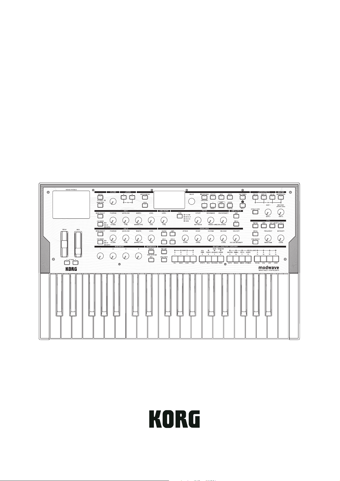
modwave
WAVETABLE SYNTHESIZER
Owner’s Manual
E1
Page 2

Contents
Contents
Getting Started . . . . . . . . . . . . . . . . . . . . . . . . . . . . . . . . . . . . . . . . . . . . . . . . . . . . . . . . . . . . . . . . . . . . . . . . . . . . . . . . . . . . . . . . . . . . . . . . 1
About the modwave manuals . . . . . . . . . . . . . . . . . . . . . . . . . . . . . . . . . . . . . . . . . . . . . . . . . . . . . . . . . . . . . . . . . . . . . . . . . . . . . . . . . . . . . . . . . . . . . 1
If you don’t usually read manuals... . . . . . . . . . . . . . . . . . . . . . . . . . . . . . . . . . . . . . . . . . . . . . . . . . . . . . . . . . . . . . . . . . . . . . . . . . . . . . . . . . . . . . . . . 1
Navigation. . . . . . . . . . . . . . . . . . . . . . . . . . . . . . . . . . . . . . . . . . . . . . . . . . . . . . . . . . . . . . . . . . . . . . . . . . . . . . . . . . . . . . . . . . . . . . . . . . . . . . . . . . . 1
SHIFT . . . . . . . . . . . . . . . . . . . . . . . . . . . . . . . . . . . . . . . . . . . . . . . . . . . . . . . . . . . . . . . . . . . . . . . . . . . . . . . . . . . . . . . . . . . . . . . . . . . . . 2
ENTER for accelerated editing. . . . . . . . . . . . . . . . . . . . . . . . . . . . . . . . . . . . . . . . . . . . . . . . . . . . . . . . . . . . . . . . . . . . . . . . . . . . . . . . . . . . . . . . 2
Modulation . . . . . . . . . . . . . . . . . . . . . . . . . . . . . . . . . . . . . . . . . . . . . . . . . . . . . . . . . . . . . . . . . . . . . . . . . . . . . . . . . . . . . . . . . . . . . . . . . . . . . . . . . . 2
Mod Knobs . . . . . . . . . . . . . . . . . . . . . . . . . . . . . . . . . . . . . . . . . . . . . . . . . . . . . . . . . . . . . . . . . . . . . . . . . . . . . . . . . . . . . . . . . . . . . . . . . . . . . . . . . . 2
Help pages . . . . . . . . . . . . . . . . . . . . . . . . . . . . . . . . . . . . . . . . . . . . . . . . . . . . . . . . . . . . . . . . . . . . . . . . . . . . . . . . . . . . . . . . . . . . . . . . . . . . . . . . . . 3
Structure . . . . . . . . . . . . . . . . . . . . . . . . . . . . . . . . . . . . . . . . . . . . . . . . . . . . . . . . . . . . . . . . . . . . . . . . . . . . . . . . . . . . . . . . . . . . . . . . . . . . . . . . . . . . 3
Selecting and Playing Sounds . . . . . . . . . . . . . . . . . . . . . . . . . . . . . . . . . . . . . . . . . . . . . . . . . . . . . . . . . . . . . . . . . . . . . . . . . . . . . . . . . . 4
Selecting Sounds . . . . . . . . . . . . . . . . . . . . . . . . . . . . . . . . . . . . . . . . . . . . . . . . . . . . . . . . . . . . . . . . . . . . . . . . . . . . . . . . . . . . . . . . . . . . . . . . . . . . . . . . . 4
Selecting Performances from the display . . . . . . . . . . . . . . . . . . . . . . . . . . . . . . . . . . . . . . . . . . . . . . . . . . . . . . . . . . . . . . . . . . . . . . . . . . . . . 4
Selecting from lists. . . . . . . . . . . . . . . . . . . . . . . . . . . . . . . . . . . . . . . . . . . . . . . . . . . . . . . . . . . . . . . . . . . . . . . . . . . . . . . . . . . . . . . . . . . . . . . . . . . 4
Using Set Lists . . . . . . . . . . . . . . . . . . . . . . . . . . . . . . . . . . . . . . . . . . . . . . . . . . . . . . . . . . . . . . . . . . . . . . . . . . . . . . . . . . . . . . . . . . . . . . . . . . . . . . . . . . . . 5
Assigning a Performance to a Set List Slot. . . . . . . . . . . . . . . . . . . . . . . . . . . . . . . . . . . . . . . . . . . . . . . . . . . . . . . . . . . . . . . . . . . . . . . . . . . . . 6
Basic Editing . . . . . . . . . . . . . . . . . . . . . . . . . . . . . . . . . . . . . . . . . . . . . . . . . . . . . . . . . . . . . . . . . . . . . . . . . . . . . . . . . . . . . . . . . . . . . . . . . . 7
Home Page (PERFORM) . . . . . . . . . . . . . . . . . . . . . . . . . . . . . . . . . . . . . . . . . . . . . . . . . . . . . . . . . . . . . . . . . . . . . . . . . . . . . . . . . . . . . . . . . . . . . . . . . . . 7
Layer Programs . . . . . . . . . . . . . . . . . . . . . . . . . . . . . . . . . . . . . . . . . . . . . . . . . . . . . . . . . . . . . . . . . . . . . . . . . . . . . . . . . . . . . . . . . . . . . . . . . . . . . . . . . . . 7
Velocity Zones. . . . . . . . . . . . . . . . . . . . . . . . . . . . . . . . . . . . . . . . . . . . . . . . . . . . . . . . . . . . . . . . . . . . . . . . . . . . . . . . . . . . . . . . . . . . . . . . . . . . . . . . . . . . 8
Keyboard Zones . . . . . . . . . . . . . . . . . . . . . . . . . . . . . . . . . . . . . . . . . . . . . . . . . . . . . . . . . . . . . . . . . . . . . . . . . . . . . . . . . . . . . . . . . . . . . . . . . . . . . . . . . . 8
Program Setup . . . . . . . . . . . . . . . . . . . . . . . . . . . . . . . . . . . . . . . . . . . . . . . . . . . . . . . . . . . . . . . . . . . . . . . . . . . . . . . . . . . . . . . . . . . . . . . . . . . . . . . . . . . 9
Voice Assign. . . . . . . . . . . . . . . . . . . . . . . . . . . . . . . . . . . . . . . . . . . . . . . . . . . . . . . . . . . . . . . . . . . . . . . . . . . . . . . . . . . . . . . . . . . . . . . . . . . . . . . . . . . . . 10
Layer Setup. . . . . . . . . . . . . . . . . . . . . . . . . . . . . . . . . . . . . . . . . . . . . . . . . . . . . . . . . . . . . . . . . . . . . . . . . . . . . . . . . . . . . . . . . . . . . . . . . . . . . . . . . . . . . . 12
Performance Setup . . . . . . . . . . . . . . . . . . . . . . . . . . . . . . . . . . . . . . . . . . . . . . . . . . . . . . . . . . . . . . . . . . . . . . . . . . . . . . . . . . . . . . . . . . . . . . . . . . . . . . 13
Write . . . . . . . . . . . . . . . . . . . . . . . . . . . . . . . . . . . . . . . . . . . . . . . . . . . . . . . . . . . . . . . . . . . . . . . . . . . . . . . . . . . . . . . . . . . . . . . . . . . . . . . . 14
Saving Sounds. . . . . . . . . . . . . . . . . . . . . . . . . . . . . . . . . . . . . . . . . . . . . . . . . . . . . . . . . . . . . . . . . . . . . . . . . . . . . . . . . . . . . . . . . . . . . . . . . . . . . . . . . . . 14
Name . . . . . . . . . . . . . . . . . . . . . . . . . . . . . . . . . . . . . . . . . . . . . . . . . . . . . . . . . . . . . . . . . . . . . . . . . . . . . . . . . . . . . . . . . . . . . . . . . . . . . . . . . . . . . . . . . . . 14
Editing names . . . . . . . . . . . . . . . . . . . . . . . . . . . . . . . . . . . . . . . . . . . . . . . . . . . . . . . . . . . . . . . . . . . . . . . . . . . . . . . . . . . . . . . . . . . . . . . . . . . . . . 15
Write Metadata . . . . . . . . . . . . . . . . . . . . . . . . . . . . . . . . . . . . . . . . . . . . . . . . . . . . . . . . . . . . . . . . . . . . . . . . . . . . . . . . . . . . . . . . . . . . . . . . . . . . . . . . . . 15
Compare . . . . . . . . . . . . . . . . . . . . . . . . . . . . . . . . . . . . . . . . . . . . . . . . . . . . . . . . . . . . . . . . . . . . . . . . . . . . . . . . . . . . . . . . . . . . . . . . . . . . . . . . . . . . . . . . 15
Using Compare . . . . . . . . . . . . . . . . . . . . . . . . . . . . . . . . . . . . . . . . . . . . . . . . . . . . . . . . . . . . . . . . . . . . . . . . . . . . . . . . . . . . . . . . . . . . . . . . . . . . . 16
Delete from Database. . . . . . . . . . . . . . . . . . . . . . . . . . . . . . . . . . . . . . . . . . . . . . . . . . . . . . . . . . . . . . . . . . . . . . . . . . . . . . . . . . . . . . . . . . . . . . . . . . . . 16
Using Delete. . . . . . . . . . . . . . . . . . . . . . . . . . . . . . . . . . . . . . . . . . . . . . . . . . . . . . . . . . . . . . . . . . . . . . . . . . . . . . . . . . . . . . . . . . . . . . . . . . . . . . . . 16
Wavetable Osc. . . . . . . . . . . . . . . . . . . . . . . . . . . . . . . . . . . . . . . . . . . . . . . . . . . . . . . . . . . . . . . . . . . . . . . . . . . . . . . . . . . . . . . . . . . . . . . . 17
Overview . . . . . . . . . . . . . . . . . . . . . . . . . . . . . . . . . . . . . . . . . . . . . . . . . . . . . . . . . . . . . . . . . . . . . . . . . . . . . . . . . . . . . . . . . . . . . . . . . . . . . . . . . . . . . . . . 17
Osc 1 Waveform . . . . . . . . . . . . . . . . . . . . . . . . . . . . . . . . . . . . . . . . . . . . . . . . . . . . . . . . . . . . . . . . . . . . . . . . . . . . . . . . . . . . . . . . . . . . . . . . . . . . . . . . . 17
Modes A and A/B . . . . . . . . . . . . . . . . . . . . . . . . . . . . . . . . . . . . . . . . . . . . . . . . . . . . . . . . . . . . . . . . . . . . . . . . . . . . . . . . . . . . . . . . . . . . . . . . . . . 17
Sample Mode. . . . . . . . . . . . . . . . . . . . . . . . . . . . . . . . . . . . . . . . . . . . . . . . . . . . . . . . . . . . . . . . . . . . . . . . . . . . . . . . . . . . . . . . . . . . . . . . . . . . . . . 19
Osc 1/2 Position . . . . . . . . . . . . . . . . . . . . . . . . . . . . . . . . . . . . . . . . . . . . . . . . . . . . . . . . . . . . . . . . . . . . . . . . . . . . . . . . . . . . . . . . . . . . . . . . . . . . . . . . . 20
Osc 1/2 Morph. . . . . . . . . . . . . . . . . . . . . . . . . . . . . . . . . . . . . . . . . . . . . . . . . . . . . . . . . . . . . . . . . . . . . . . . . . . . . . . . . . . . . . . . . . . . . . . . . . . . . . . . . . . 21
Osc 1/2 Details. . . . . . . . . . . . . . . . . . . . . . . . . . . . . . . . . . . . . . . . . . . . . . . . . . . . . . . . . . . . . . . . . . . . . . . . . . . . . . . . . . . . . . . . . . . . . . . . . . . . . . . . . . . 23
Mixer & Sub Osc . . . . . . . . . . . . . . . . . . . . . . . . . . . . . . . . . . . . . . . . . . . . . . . . . . . . . . . . . . . . . . . . . . . . . . . . . . . . . . . . . . . . . . . . . . . . . . . . . . . . . . . . . 24
Osc 1 . . . . . . . . . . . . . . . . . . . . . . . . . . . . . . . . . . . . . . . . . . . . . . . . . . . . . . . . . . . . . . . . . . . . . . . . . . . . . . . . . . . . . . . . . . . . . . . . . . . . . . . . . . . . . . . 24
Osc 2 . . . . . . . . . . . . . . . . . . . . . . . . . . . . . . . . . . . . . . . . . . . . . . . . . . . . . . . . . . . . . . . . . . . . . . . . . . . . . . . . . . . . . . . . . . . . . . . . . . . . . . . . . . . . . . . 24
Sub/Noise . . . . . . . . . . . . . . . . . . . . . . . . . . . . . . . . . . . . . . . . . . . . . . . . . . . . . . . . . . . . . . . . . . . . . . . . . . . . . . . . . . . . . . . . . . . . . . . . . . . . . . . . . . 24
Analyzer . . . . . . . . . . . . . . . . . . . . . . . . . . . . . . . . . . . . . . . . . . . . . . . . . . . . . . . . . . . . . . . . . . . . . . . . . . . . . . . . . . . . . . . . . . . . . . . . . . . . . 26
Motion Sequencing 2.0. . . . . . . . . . . . . . . . . . . . . . . . . . . . . . . . . . . . . . . . . . . . . . . . . . . . . . . . . . . . . . . . . . . . . . . . . . . . . . . . . . . . . . . . 27
What is Motion Sequencing 2.0? . . . . . . . . . . . . . . . . . . . . . . . . . . . . . . . . . . . . . . . . . . . . . . . . . . . . . . . . . . . . . . . . . . . . . . . . . . . . . . . . . . . . . . . . . 27
Motion Seq Overview . . . . . . . . . . . . . . . . . . . . . . . . . . . . . . . . . . . . . . . . . . . . . . . . . . . . . . . . . . . . . . . . . . . . . . . . . . . . . . . . . . . . . . . . . . . . . . . . . . . . 28
Motion Sequence Recording . . . . . . . . . . . . . . . . . . . . . . . . . . . . . . . . . . . . . . . . . . . . . . . . . . . . . .
Step recording Pitch . . . . . . . . . . . . . . . . . . . . . . . . . . . . . . . . . . . . . . . . . . . . . . . . . . . . . . . . . . . . . . . . . . . . . . . . . . . . . . . . . . . . . . . . . . . . . . . . 29
Real-time recording for Seq Lanes A-D. . . . . . . . . . . . . . . . . . . . . . . . . . . . . . . . . . . . . . . . . . . . . . . . . . . . . . . . . . . . . . . . . . . . . . . . . . . . . . . 29
Motion Sequence editing . . . . . . . . . . . . . . . . . . . . . . . . . . . . . . . . . . . . . . . . . . . . . . . . . . . . . . . . . . . . . . . . . . . . . . . . . . . . . . . . . . . . . . . . . . . . . . . . 31
Editing Lanes . . . . . . . . . . . . . . . . . . . . . . . . . . . . . . . . . . . . . . . . . . . . . . . . . . . . . . . . . . . . . . . . . . . . . . . . . . . . . . . . . . . . . . . . . . . . . . . . . . . . . . . 31
Editing Steps . . . . . . . . . . . . . . . . . . . . . . . . . . . . . . . . . . . . . . . . . . . . . . . . . . . . . . . . . . . . . . . . . . . . . . . . . . . . . . . . . . . . . . . . . . . . . . . . . . . . . . . 31
Step Solo mode. . . . . . . . . . . . . . . . . . . . . . . . . . . . . . . . . . . . . . . . . . . . . . . . . . . . . . . . . . . . . . . . . . . . . . . . . . . . . . . . . . . . . . . . . . . . . . . . . . . . . 31
Motion Sequencer . . . . . . . . . . . . . . . . . . . . . . . . . . . . . . . . . . . . . . . . . . . . . . . . . . . . . . . . . . . . . . . . . . . . . . . . . . . . . . . . . . . . . . . . . . . . . . . . . . . . . . . 32
Master Lane . . . . . . . . . . . . . . . . . . . . . . . . . . . . . . . . . . . . . . . . . . . . . . . . . . . . . . . . . . . . . . . . . . . . . . . . . . . . . . . . . . . . . . . . . . . . . . . . . . . . . . . . . . . . . 33
Standard Lane Controls . . . . . . . . . . . . . . . . . . . . . . . . . . . . . . . . . . . . . . . . . . . . . . . . . . . . . . . . . . . . . . . . . . . . . . . . . . . . . . . . . . . . . . . . . . . . . . . . . . 34
. . . . . . . . . . . . . . . . . . . . . . . . . . . . . . . . . . . . . . . 29
i
Page 3

Contents
Step Probability . . . . . . . . . . . . . . . . . . . . . . . . . . . . . . . . . . . . . . . . . . . . . . . . . . . . . . . . . . . . . . . . . . . . . . . . . . . . . . . . . . . . . . . . . . . . . . . . . . . . . . . . . 35
Timing Lane probability . . . . . . . . . . . . . . . . . . . . . . . . . . . . . . . . . . . . . . . . . . . . . . . . . . . . . . . . . . . . . . . . . . . . . . . . . . . . . . . . . . . . . . . . . . . . . 35
Timing . . . . . . . . . . . . . . . . . . . . . . . . . . . . . . . . . . . . . . . . . . . . . . . . . . . . . . . . . . . . . . . . . . . . . . . . . . . . . . . . . . . . . . . . . . . . . . . . . . . . . . . . . . . . . . . . . . 35
Timing Lane . . . . . . . . . . . . . . . . . . . . . . . . . . . . . . . . . . . . . . . . . . . . . . . . . . . . . . . . . . . . . . . . . . . . . . . . . . . . . . . . . . . . . . . . . . . . . . . . . . . . . . . . 35
Timing Lane Step . . . . . . . . . . . . . . . . . . . . . . . . . . . . . . . . . . . . . . . . . . . . . . . . . . . . . . . . . . . . . . . . . . . . . . . . . . . . . . . . . . . . . . . . . . . . . . . . . . . 37
Pitch . . . . . . . . . . . . . . . . . . . . . . . . . . . . . . . . . . . . . . . . . . . . . . . . . . . . . . . . . . . . . . . . . . . . . . . . . . . . . . . . . . . . . . . . . . . . . . . . . . . . . . . . . . . . . . . . . . . . 38
Pitch Lane . . . . . . . . . . . . . . . . . . . . . . . . . . . . . . . . . . . . . . . . . . . . . . . . . . . . . . . . . . . . . . . . . . . . . . . . . . . . . . . . . . . . . . . . . . . . . . . . . . . . . . . . . . 38
Pitch Lane Step . . . . . . . . . . . . . . . . . . . . . . . . . . . . . . . . . . . . . . . . . . . . . . . . . . . . . . . . . . . . . . . . . . . . . . . . . . . . . . . . . . . . . . . . . . . . . . . . . . . . . 40
Shape . . . . . . . . . . . . . . . . . . . . . . . . . . . . . . . . . . . . . . . . . . . . . . . . . . . . . . . . . . . . . . . . . . . . . . . . . . . . . . . . . . . . . . . . . . . . . . . . . . . . . . . . . . . . . . . . . . . 41
Shape Lane . . . . . . . . . . . . . . . . . . . . . . . . . . . . . . . . . . . . . . . . . . . . . . . . . . . . . . . . . . . . . . . . . . . . . . . . . . . . . . . . . . . . . . . . . . . . . . . . . . . . . . . . . 41
Shape Lane Step . . . . . . . . . . . . . . . . . . . . . . . . . . . . . . . . . . . . . . . . . . . . . . . . . . . . . . . . . . . . . . . . . . . . . . . . . . . . . . . . . . . . . . . . . . . . . . . . . . . . 41
Seq A/B/C/D . . . . . . . . . . . . . . . . . . . . . . . . . . . . . . . . . . . . . . . . . . . . . . . . . . . . . . . . . . . . . . . . . . . . . . . . . . . . . . . . . . . . . . . . . . . . . . . . . . . . . . . . . . . . . 42
Seq Lane . . . . . . . . . . . . . . . . . . . . . . . . . . . . . . . . . . . . . . . . . . . . . . . . . . . . . . . . . . . . . . . . . . . . . . . . . . . . . . . . . . . . . . . . . . . . . . . . . . . . . . . . . . . 42
Seq Lane Step . . . . . . . . . . . . . . . . . . . . . . . . . . . . . . . . . . . . . . . . . . . . . . . . . . . . . . . . . . . . . . . . . . . . . . . . . . . . . . . . . . . . . . . . . . . . . . . . . . . . . . 43
Motion Sequence Utility . . . . . . . . . . . . . . . . . . . . . . . . . . . . . . . . . . . . . . . . . . . . . . . . . . . . . . . . . . . . . . . . . . . . . . . . . . . . . . . . . . . . . . . . . . . . . . . . . 44
Cut Steps, Copy Steps, Paste Steps, Insert Steps . . . . . . . . . . . . . . . . . . . . . . . . . . . . . . . . . . . . . . . . . . . . . . . . . . . . . . . . . . . . . . . . . . . . . . 44
Clear . . . . . . . . . . . . . . . . . . . . . . . . . . . . . . . . . . . . . . . . . . . . . . . . . . . . . . . . . . . . . . . . . . . . . . . . . . . . . . . . . . . . . . . . . . . . . . . . . . . . . . . . . . . . . . . 44
Scale Timing . . . . . . . . . . . . . . . . . . . . . . . . . . . . . . . . . . . . . . . . . . . . . . . . . . . . . . . . . . . . . . . . . . . . . . . . . . . . . . . . . . . . . . . . . . . . . . . . . . . . . . . . 44
Kaoss Physics. . . . . . . . . . . . . . . . . . . . . . . . . . . . . . . . . . . . . . . . . . . . . . . . . . . . . . . . . . . . . . . . . . . . . . . . . . . . . . . . . . . . . . . . . . . . . . . . . 45
Overview . . . . . . . . . . . . . . . . . . . . . . . . . . . . . . . . . . . . . . . . . . . . . . . . . . . . . . . . . . . . . . . . . . . . . . . . . . . . . . . . . . . . . . . . . . . . . . . . . . . . . . . . . . . . . . . . 45
Using Kaoss Physics to create specific results. . . . . . . . . . . . . . . . . . . . . . . . . . . . . . . . . . . . . . . . . . . . . . . . . . . . . . . . . . . . . . . . . . . . . . . . . 45
Kaoss Physics and MIDI. . . . . . . . . . . . . . . . . . . . . . . . . . . . . . . . . . . . . . . . . . . . . . . . . . . . . . . . . . . . . . . . . . . . . . . . . . . . . . . . . . . . . . . . . . . . . . 45
Kaoss Physics . . . . . . . . . . . . . . . . . . . . . . . . . . . . . . . . . . . . . . . . . . . . . . . . . . . . . . . . . . . . . . . . . . . . . . . . . . . . . . . . . . . . . . . . . . . . . . . . . . . . . . . . . . . . 46
Kaoss Physics Details. . . . . . . . . . . . . . . . . . . . . . . . . . . . . . . . . . . . . . . . . . . . . . . . . . . . . . . . . . . . . . . . . . . . . . . . . . . . . . . . . . . . . . . . . . . . . . . . . . . . . 47
Kaoss Launch . . . . . . . . . . . . . . . . . . . . . . . . . . . . . . . . . . . . . . . . . . . . . . . . . . . . . . . . . . . . . . . . . . . . . . . . . . . . . . . . . . . . . . . . . . . . . . . . . . . . . . . . . . . . 48
Arpeggiator . . . . . . . . . . . . . . . . . . . . . . . . . . . . . . . . . . . . . . . . . . . . . . . . . . . . . . . . . . . . . . . . . . . . . . . . . . . . . . . . . . . . . . . . . . . . . . . . . . 49
Arpeggiator . . . . . . . . . . . . . . . . . . . . . . . . . . . . . . . . . . . . . . . . . . . . . . . . . . . . . . . . . . . . . . . . . . . . . . . . . . . . . . . . . . . . . . . . . . . . . . . . . . . . . . . . . . . . . 49
Filter. . . . . . . . . . . . . . . . . . . . . . . . . . . . . . . . . . . . . . . . . . . . . . . . . . . . . . . . . . . . . . . . . . . . . . . . . . . . . . . . . . . . . . . . . . . . . . . . . . . . . . . . . 51
Filter . . . . . . . . . . . . . . . . . . . . . . . . . . . . . . . . . . . . . . . . . . . . . . . . . . . . . . . . . . . . . . . . . . . . . . . . . . . . . . . . . . . . . . . . . . . . . . . . . . . . . . . . . . . . . . . . . . . . 51
2-Pole LP/HP/BP/BR . . . . . . . . . . . . . . . . . . . . . . . . . . . . . . . . . . . . . . . . . . . . . . . . . . . . . . . . . . . . . . . . . . . . . . . . . . . . . . . . . . . . . . . . . . . . . . . . . 53
4-Pole LP/HP/BP/BR . . . . . . . . . . . . . . . . . . . . . . . . . . . . . . . . . . . . . . . . . . . . . . . . . . . . . . . . . . . . . . . . . . . . . . . . . . . . . . . . . . . . . . . . . . . . . . . . . 53
MS-20 LP/HP and Polysix . . . . . . . . . . . . . . . . . . . . . . . . . . . . . . . . . . . . . . . . . . . . . . . . . . . . . . . . . . . . . . . . . . . . . . . . . . . . . . . . . . . . . . . . . . . . 53
Multi Filter . . . . . . . . . . . . . . . . . . . . . . . . . . . . . . . . . . . . . . . . . . . . . . . . . . . . . . . . . . . . . . . . . . . . . . . . . . . . . . . . . . . . . . . . . . . . . . . . . . . . . . . . . . 54
Multi Filter. . . . . . . . . . . . . . . . . . . . . . . . . . . . . . . . . . . . . . . . . . . . . . . . . . . . . . . . . . . . . . . . . . . . . . . . . . . . . . . . . . . . . . . . . . . . . . . . . . . . . . . . . . . . . . . 54
What’s a Multi Filter? . . . . . . . . . . . . . . . . . . . . . . . . . . . . . . . . . . . . . . . . . . . . . . . . . . . . . . . . . . . . . . . . . . . . . . . . . . . . . . . . . . . . . . . . . . . . . . . . 55
Manual . . . . . . . . . . . . . . . . . . . . . . . . . . . . . . . . . . . . . . . . . . . . . . . . . . . . . . . . . . . . . . . . . . . . . . . . . . . . . . . . . . . . . . . . . . . . . . . . . . . . . . . . . . . . . 55
Filter Mod . . . . . . . . . . . . . . . . . . . . . . . . . . . . . . . . . . . . . . . . . . . . . . . . . . . . . . . . . . . . . . . . . . . . . . . . . . . . . . . . . . . . . . . . . . . . . . . . . . . . . . . . . . . . . . . 55
Filter Key Track . . . . . . . . . . . . . . . . . . . . . . . . . . . . . . . . . . . . . . . . . . . . . . . . . . . . . . . . . . . . . . . . . . . . . . . . . . . . . . . . . . . . . . . . . . . . . . . . . . . . . . . . . . 57
How Key Track works: Keys and Slopes. . . . . . . . . . . . . . . . . . . . . . . . . . . . . . . . . . . . . . . . . . . . . . . . . . . . . . . . . . . . . . . . . . . . . . . . . . . . . . . 57
Pitch . . . . . . . . . . . . . . . . . . . . . . . . . . . . . . . . . . . . . . . . . . . . . . . . . . . . . . . . . . . . . . . . . . . . . . . . . . . . . . . . . . . . . . . . . . . . . . . . . . . . . . . . . 59
Osc Pitch . . . . . . . . . . . . . . . . . . . . . . . . . . . . . . . . . . . . . . . . . . . . . . . . . . . . . . . . . . . . . . . . . . . . . . . . . . . . . . . . . . . . . . . . . . . . . . . . . . . . . . . . . . . . . . . . 59
Osc 1 . . . . . . . . . . . . . . . . . . . . . . . . . . . . . . . . . . . . . . . . . . . . . . . . . . . . . . . . . . . . . . . . . . . . . . . . . . . . . . . . . . . . . . . . . . . . . . . . . . . . . . . . . . . . . . . 59
Osc 2 . . . . . . . . . . . . . . . . . . . . . . . . . . . . . . . . . . . . . . . . . . . . . . . . . . . . . . . . . . . . . . . . . . . . . . . . . . . . . . . . . . . . . . . . . . . . . . . . . . . . . . . . . . . . . . . 59
Common Pitch . . . . . . . . . . . . . . . . . . . . . . . . . . . . . . . . . . . . . . . . . . . . . . . . . . . . . . . . . . . . . . . . . . . . . . . . . . . . . . . . . . . . . . . . . . . . . . . . . . . . . . . . . . 60
Pitch Mod . . . . . . . . . . . . . . . . . . . . . . . . . . . . . . . . . . . . . . . . . . . . . . . . . . . . . . . . . . . . . . . . . . . . . . . . . . . . . . . . . . . . . . . . . . . . . . . . . . . . . . . . . . . . . . . 61
Amp . . . . . . . . . . . . . . . . . . . . . . . . . . . . . . . . . . . . . . . . . . . . . . . . . . . . . . . . . . . . . . . . . . . . . . . . . . . . . . . . . . . . . . . . . . . . . . . . . . . . . . . . . 62
Amp . . . . . . . . . . . . . . . . . . . . . . . . . . . . . . . . . . . . . . . . . . . . . . . . . . . . . . . . . . . . . . . . . . . . . . . . . . . . . . . . . . . . . . . . . . . . . . . . . . . . . . . . . . . . . . . . . . . . 62
Amp Key Track. . . . . . . . . . . . . . . . . . . . . . . . . . . . . . . . . . . . . . . . . . . . . . . . . . . . . . . . . . . . . . . . . . . . . . . . . . . . . . . . . . . . . . . . . . . . . . . . . . . . . . . . . . . 63
Modulation . . . . . . . . . . . . . . . . . . . . . . . . . . . . . . . . . . . . . . . . . . . . . . . . . . . . . . . . . . . . . . . . . . . . . . . . . . . . . . . . . . . . . . . . . . . . . . . . . . 64
Using Modulation . . . . . . . . . . . . . . . . . . . . . . . . . . . . . . . . . . . . . . . . . . . . . . . . . . . . . . . . . . . . . . . . . . . . . . . . . . . . . . . . . . . . . . . . . . . . . . . . . . . . . . . 64
Modulation Overview . . . . . . . . . . . . . . . . . . . . . . . . . . . . . . . . . . . . . . . . . . . . . . . . . . . . . . . .
Adding Modulation Routings. . . . . . . . . . . . . . . . . . . . . . . . . . . . . . . . . . . . . . . . . . . . . . . . . . . . . . . . . . . . . . . . . . . . . . . . . . . . . . . . . . . . . . . . 64
Viewing and Editing Modulations . . . . . . . . . . . . . . . . . . . . . . . . . . . . . . . . . . . . . . . . . . . . . . . . . . . . . . . . . . . . . . . . . . . . . . . . . . . . . . . . . . . 65
Mod Knobs . . . . . . . . . . . . . . . . . . . . . . . . . . . . . . . . . . . . . . . . . . . . . . . . . . . . . . . . . . . . . . . . . . . . . . . . . . . . . . . . . . . . . . . . . . . . . . . . . . . . . . . . . . . . . . 67
Modulation Sources . . . . . . . . . . . . . . . . . . . . . . . . . . . . . . . . . . . . . . . . . . . . . . . . . . . . . . . . . . . . . . . . . . . . . . . . . . . . . . . . . . . . . . . . . . . . . . . . . . . . . 67
Controllers. . . . . . . . . . . . . . . . . . . . . . . . . . . . . . . . . . . . . . . . . . . . . . . . . . . . . . . . . . . . . . . . . . . . . . . . . . . . . . . . . . . . . . . . . . . . . . . . . . . . . . . . . . 67
Mod Knobs . . . . . . . . . . . . . . . . . . . . . . . . . . . . . . . . . . . . . . . . . . . . . . . . . . . . . . . . . . . . . . . . . . . . . . . . . . . . . . . . . . . . . . . . . . . . . . . . . . . . . . . . . 69
Generators . . . . . . . . . . . . . . . . . . . . . . . . . . . . . . . . . . . . . . . . . . . . . . . . . . . . . . . . . . . . . . . . . . . . . . . . . . . . . . . . . . . . . . . . . . . . . . . . . . . . . . . . . 69
CC +. . . . . . . . . . . . . . . . . . . . . . . . . . . . . . . . . . . . . . . . . . . . . . . . . . . . . . . . . . . . . . . . . . . . . . . . . . . . . . . . . . . . . . . . . . . . . . . . . . . . . . . . . . . . . . . . 69
CC +/- . . . . . . . . . . . . . . . . . . . . . . . . . . . . . . . . . . . . . . . . . . . . . . . . . . . . . . . . . . . . . . . . . . . . . . . . . . . . . . . . . . . . . . . . . . . . . . . . . . . . . . . . . . . . . . 69
Envelopes . . . . . . . . . . . . . . . . . . . . . . . . . . . . . . . . . . . . . . . . . . . . . . . . . . . . . . . . . . . . . . . . . . . . . . . . . . . . . . . . . . . . . . . . . . . . . . . . . . . . 70
Filter/Amp/Osc 1/Osc 2 Envelope . . . . . . . . . . . . . . . . . . . . . . . . . . . . . . . . . . . . . . . . . . . . . . . . . . . . . . . . . . . . . . . . . . . . . . . . . . . . . . . . . . . . . . . . 70
Filter/Amp/Osc 1/Osc 2 Envelope Curve . . . . . . . . . . . . . . . . . . . . . . . . . . . . . . . . . . . . . . . . . . . . . . . . . . . . . . . . . . . . . . . . . . . . . . . . . . . . . . . . . . 70
. . . . . . . . . . . . . . . . . . . . . . . . . . . . . . . . . . . . . . . 64
ii
Page 4

Contents
Filter/Amp/Osc 1/Osc 2 Envelope Trigger. . . . . . . . . . . . . . . . . . . . . . . . . . . . . . . . . . . . . . . . . . . . . . . . . . . . . . . . . . . . . . . . . . . . . . . . . . . . . . . . . 71
LFOs . . . . . . . . . . . . . . . . . . . . . . . . . . . . . . . . . . . . . . . . . . . . . . . . . . . . . . . . . . . . . . . . . . . . . . . . . . . . . . . . . . . . . . . . . . . . . . . . . . . . . . . . . 73
Filter/Amp/Pitch/Osc 1/Osc 2 LFO . . . . . . . . . . . . . . . . . . . . . . . . . . . . . . . . . . . . . . . . . . . . . . . . . . . . . . . . . . . . . . . . . . . . . . . . . . . . . . . . . . . . . . . . 73
Modulation Processors. . . . . . . . . . . . . . . . . . . . . . . . . . . . . . . . . . . . . . . . . . . . . . . . . . . . . . . . . . . . . . . . . . . . . . . . . . . . . . . . . . . . . . . . 76
Overview . . . . . . . . . . . . . . . . . . . . . . . . . . . . . . . . . . . . . . . . . . . . . . . . . . . . . . . . . . . . . . . . . . . . . . . . . . . . . . . . . . . . . . . . . . . . . . . . . . . . . . . . . . . . . . . . 76
Gate. . . . . . . . . . . . . . . . . . . . . . . . . . . . . . . . . . . . . . . . . . . . . . . . . . . . . . . . . . . . . . . . . . . . . . . . . . . . . . . . . . . . . . . . . . . . . . . . . . . . . . . . . . . . . . . . . . . . . 76
Offset . . . . . . . . . . . . . . . . . . . . . . . . . . . . . . . . . . . . . . . . . . . . . . . . . . . . . . . . . . . . . . . . . . . . . . . . . . . . . . . . . . . . . . . . . . . . . . . . . . . . . . . . . . . . . . . . . . . 77
Quantize . . . . . . . . . . . . . . . . . . . . . . . . . . . . . . . . . . . . . . . . . . . . . . . . . . . . . . . . . . . . . . . . . . . . . . . . . . . . . . . . . . . . . . . . . . . . . . . . . . . . . . . . . . . . . . . . 78
Scale . . . . . . . . . . . . . . . . . . . . . . . . . . . . . . . . . . . . . . . . . . . . . . . . . . . . . . . . . . . . . . . . . . . . . . . . . . . . . . . . . . . . . . . . . . . . . . . . . . . . . . . . . . . . . . . . . . . . 79
Curve . . . . . . . . . . . . . . . . . . . . . . . . . . . . . . . . . . . . . . . . . . . . . . . . . . . . . . . . . . . . . . . . . . . . . . . . . . . . . . . . . . . . . . . . . . . . . . . . . . . . . . . . . . . . . . . . . . . 79
Smooth . . . . . . . . . . . . . . . . . . . . . . . . . . . . . . . . . . . . . . . . . . . . . . . . . . . . . . . . . . . . . . . . . . . . . . . . . . . . . . . . . . . . . . . . . . . . . . . . . . . . . . . . . . . . . . . . . 81
Sum. . . . . . . . . . . . . . . . . . . . . . . . . . . . . . . . . . . . . . . . . . . . . . . . . . . . . . . . . . . . . . . . . . . . . . . . . . . . . . . . . . . . . . . . . . . . . . . . . . . . . . . . . . . . . . . . . . . . . 81
Effects . . . . . . . . . . . . . . . . . . . . . . . . . . . . . . . . . . . . . . . . . . . . . . . . . . . . . . . . . . . . . . . . . . . . . . . . . . . . . . . . . . . . . . . . . . . . . . . . . . . . . . . 83
Overview . . . . . . . . . . . . . . . . . . . . . . . . . . . . . . . . . . . . . . . . . . . . . . . . . . . . . . . . . . . . . . . . . . . . . . . . . . . . . . . . . . . . . . . . . . . . . . . . . . . . . . . . . . . . . . . . 83
Main page. . . . . . . . . . . . . . . . . . . . . . . . . . . . . . . . . . . . . . . . . . . . . . . . . . . . . . . . . . . . . . . . . . . . . . . . . . . . . . . . . . . . . . . . . . . . . . . . . . . . . . . . . . . . . . . 83
Level controls. . . . . . . . . . . . . . . . . . . . . . . . . . . . . . . . . . . . . . . . . . . . . . . . . . . . . . . . . . . . . . . . . . . . . . . . . . . . . . . . . . . . . . . . . . . . . . . . . . . . . . . 84
Edit page . . . . . . . . . . . . . . . . . . . . . . . . . . . . . . . . . . . . . . . . . . . . . . . . . . . . . . . . . . . . . . . . . . . . . . . . . . . . . . . . . . . . . . . . . . . . . . . . . . . . . . . . . . . . . . . . 84
Pre FX . . . . . . . . . . . . . . . . . . . . . . . . . . . . . . . . . . . . . . . . . . . . . . . . . . . . . . . . . . . . . . . . . . . . . . . . . . . . . . . . . . . . . . . . . . . . . . . . . . . . . . . . . . . . . . . . . . . 85
Decimator . . . . . . . . . . . . . . . . . . . . . . . . . . . . . . . . . . . . . . . . . . . . . . . . . . . . . . . . . . . . . . . . . . . . . . . . . . . . . . . . . . . . . . . . . . . . . . . . . . . . . . . . . . 85
Graphic EQ . . . . . . . . . . . . . . . . . . . . . . . . . . . . . . . . . . . . . . . . . . . . . . . . . . . . . . . . . . . . . . . . . . . . . . . . . . . . . . . . . . . . . . . . . . . . . . . . . . . . . . . . . 85
Guitar Amp . . . . . . . . . . . . . . . . . . . . . . . . . . . . . . . . . . . . . . . . . . . . . . . . . . . . . . . . . . . . . . . . . . . . . . . . . . . . . . . . . . . . . . . . . . . . . . . . . . . . . . . . . 85
Modern Compressor . . . . . . . . . . . . . . . . . . . . . . . . . . . . . . . . . . . . . . . . . . . . . . . . . . . . . . . . . . . . . . . . . . . . . . . . . . . . . . . . . . . . . . . . . . . . . . . . 85
Parametric EQ . . . . . . . . . . . . . . . . . . . . . . . . . . . . . . . . . . . . . . . . . . . . . . . . . . . . . . . . . . . . . . . . . . . . . . . . . . . . . . . . . . . . . . . . . . . . . . . . . . . . . . 85
Red Compressor . . . . . . . . . . . . . . . . . . . . . . . . . . . . . . . . . . . . . . . . . . . . . . . . . . . . . . . . . . . . . . . . . . . . . . . . . . . . . . . . . . . . . . . . . . . . . . . . . . . . 85
Ring Modulator . . . . . . . . . . . . . . . . . . . . . . . . . . . . . . . . . . . . . . . . . . . . . . . . . . . . . . . . . . . . . . . . . . . . . . . . . . . . . . . . . . . . . . . . . . . . . . . . . . . . . 85
Tremolo . . . . . . . . . . . . . . . . . . . . . . . . . . . . . . . . . . . . . . . . . . . . . . . . . . . . . . . . . . . . . . . . . . . . . . . . . . . . . . . . . . . . . . . . . . . . . . . . . . . . . . . . . . . . 85
Wave Shaper . . . . . . . . . . . . . . . . . . . . . . . . . . . . . . . . . . . . . . . . . . . . . . . . . . . . . . . . . . . . . . . . . . . . . . . . . . . . . . . . . . . . . . . . . . . . . . . . . . . . . . . 85
Mod FX. . . . . . . . . . . . . . . . . . . . . . . . . . . . . . . . . . . . . . . . . . . . . . . . . . . . . . . . . . . . . . . . . . . . . . . . . . . . . . . . . . . . . . . . . . . . . . . . . . . . . . . . . . . . . . . . . . 86
Black Chorus/Flanger . . . . . . . . . . . . . . . . . . . . . . . . . . . . . . . . . . . . . . . . . . . . . . . . . . . . . . . . . . . . . . . . . . . . . . . . . . . . . . . . . . . . . . . . . . . . . . . 86
Black Phase . . . . . . . . . . . . . . . . . . . . . . . . . . . . . . . . . . . . . . . . . . . . . . . . . . . . . . . . . . . . . . . . . . . . . . . . . . . . . . . . . . . . . . . . . . . . . . . . . . . . . . . . . 86
CX-3 Vibrato Chorus . . . . . . . . . . . . . . . . . . . . . . . . . . . . . . . . . . . . . . . . . . . . . . . . . . . . . . . . . . . . . . . . . . . . . . . . . . . . . . . . . . . . . . . . . . . . . . . . 86
EP Chorus . . . . . . . . . . . . . . . . . . . . . . . . . . . . . . . . . . . . . . . . . . . . . . . . . . . . . . . . . . . . . . . . . . . . . . . . . . . . . . . . . . . . . . . . . . . . . . . . . . . . . . . . . . 86
Harmonic Chorus . . . . . . . . . . . . . . . . . . . . . . . . . . . . . . . . . . . . . . . . . . . . . . . . . . . . . . . . . . . . . . . . . . . . . . . . . . . . . . . . . . . . . . . . . . . . . . . . . . . 86
Modern Chorus . . . . . . . . . . . . . . . . . . . . . . . . . . . . . . . . . . . . . . . . . . . . . . . . . . . . . . . . . . . . . . . . . . . . . . . . . . . . . . . . . . . . . . . . . . . . . . . . . . . . . 86
Modern Phaser . . . . . . . . . . . . . . . . . . . . . . . . . . . . . . . . . . . . . . . . . . . . . . . . . . . . . . . . . . . . . . . . . . . . . . . . . . . . . . . . . . . . . . . . . . . . . . . . . . . . . 86
Orange Phase. . . . . . . . . . . . . . . . . . . . . . . . . . . . . . . . . . . . . . . . . . . . . . . . . . . . . . . . . . . . . . . . . . . . . . . . . . . . . . . . . . . . . . . . . . . . . . . . . . . . . . . 86
Polysix Ensemble . . . . . . . . . . . . . . . . . . . . . . . . . . . . . . . . . . . . . . . . . . . . . . . . . . . . . . . . . . . . . . . . . . . . . . . . . . . . . . . . . . . . . . . . . . . . . . . . . . . 86
Small Phase. . . . . . . . . . . . . . . . . . . . . . . . . . . . . . . . . . . . . . . . . . . . . . . . . . . . . . . . . . . . . . . . . . . . . . . . . . . . . . . . . . . . . . . . . . . . . . . . . . . . . . . . . 86
Talking Modulator . . . . . . . . . . . . . . . . . . . . . . . . . . . . . . . . . . . . . . . . . . . . . . . . . . . . . . . . . . . . . . . . . . . . . . . . . . . . . . . . . . . . . . . . . . . . . . . . . . 86
Vintage Chorus . . . . . . . . . . . . . . . . . . . . . . . . . . . . . . . . . . . . . . . . . . . . . . . . . . . . . . . . . . . . . . . . . . . . . . . . . . . . . . . . . . . . . . . . . . . . . . . . . . . . . 86
Vintage Flanger. . . . . . . . . . . . . . . . . . . . . . . . . . . . . . . . . . . . . . . . . . . . . . . . . . . . . . . . . . . . . . . . . . . . . . . . . . . . . . . . . . . . . . . . . . . . . . . . . . . . . 87
Vintage/Custom Wah . . . . . . . . . . . . . . . . . . . . . . . . . . . . . . . . . . . . . . . . . . . . . . . . . . . . . . . . . . . . . . . . . . . . . . . . . . . . . . . . . . . . . . . . . . . . . . . 87
Vox Wah. . . . . . . . . . . . . . . . . . . . . . . . . . . . . . . . . . . . . . . . . . . . . . . . . . . . . . . . . . . . . . . . . . . . . . . . . . . . . . . . . . . . . . . . . . . . . . . . . . . . . . . . . . . . 87
Delay. . . . . . . . . . . . . . . . . . . . . . . . . . . . . . . . . . . . . . . . . . . . . . . . . . . . . . . . . . . . . . . . . . . . . . . . . . . . . . . . . . . . . . . . . . . . . . . . . . . . . . . . . . . . . . . . . . . . 87
L/C/R Delay . . . . . . . . . . . . . . . . . . . . . . . . . . . . . . . . . . . . . . . . . . . . . . . . . . . . . . . . . . . . . . . . . . . . . . . . . . . . . . . . . . . . . . . . . . . . . . . . . . . . . . . . . 87
Multiband Mod Delay . . . . . . . . . . . . . . . . . . . . . . . . . . . . . . . . . . . . . . . . . . . . . . . . . . . . . . . . . . . . . . . . . . . . . . . . . . . . . . . . . . . . . . . . . . . . . . . 87
Reverse Delay. . . . . . . . . . . . . . . . . . . . . . . . . . . . . . . . . . . . . . . . . . . . . . . . . . . . . . . . . . . . . . . . . . . . . . . . . . . . . . . . . . . . . . . . . . . . . . . . . . . . . . . 87
Stereo/Cross Delay. . . . . . . . . . . . . . . . . . . . . . . . . . . . . . . . . . . . . . . . . . . . . . . . . . . . . . . . . . . . . . . . . . . . . . . . . . . . . . . . . . . . . . . . . . . . . . . . . . 87
Tape Echo . . . . . . . . . . . . . . . . . . . . . . . . . . . . . . . . . . . . . . . . . . . . . . . . . . . . . . . . . . . . . . . . . . . . . . . . . . . . . . . . . . . . . . . . . . . . . . . . . . . . . . . . . . 87
Master Reverb . . . . . . . . . . . . . . . . . . . . . . . . . . . . . . . . . . . . . . . . . . . . . . . . . . . . . . . . . . . . . . . . . . . . . . . . . . . . . . . . . . . . . . . . . . . . . . . . . . . . . . . . . . . 87
Early Reflections . . . . . . . . . . . . . . . . . . . . . . . . . . . . . . . . . . . . . . . . . . . . . . . . . . . . . . .
. . . . . . . . . . . . . . . . . . . . . . . . . . . . . . . . . . . . . . . . . . . . . . . . . . . . . . . . . . . . . . . . . . . . . . . . . . . . . . . . . . . . . . . . . . . . . . . . . . . . . . . . . . . . . . 88
Overb
Master EQ . . . . . . . . . . . . . . . . . . . . . . . . . . . . . . . . . . . . . . . . . . . . . . . . . . . . . . . . . . . . . . . . . . . . . . . . . . . . . . . . . . . . . . . . . . . . . . . . . . . . . . . . . . . . . . . 88
L (Low) and H (High) . . . . . . . . . . . . . . . . . . . . . . . . . . . . . . . . . . . . . . . . . . . . . . . . . . . . . . . . . . . . . . . . . . . . . . . . . . . . . . . . . . . . . . . . . . . . . . . . 88
Mid 1 and Mid 2. . . . . . . . . . . . . . . . . . . . . . . . . . . . . . . . . . . . . . . . . . . . . . . . . . . . . . . . . . . . . . . . . . . . . . . . . . . . . . . . . . . . . . . . . . . . . . . . . . . . . 88
Randomize . . . . . . . . . . . . . . . . . . . . . . . . . . . . . . . . . . . . . . . . . . . . . . . . . . . . . . . . . . . . . . . . . . . . . . . . . . . . . . . . . . . . . . . . . . . . . . . . . . . 89
Using Randomize . . . . . . . . . . . . . . . . . . . . . . . . . . . . . . . . . . . . . . . . . . . . . . . . . . . . . . . . . . . . . . . . . . . . . . . . . . . . . . . . . . . . . . . . . . . . . . . . . . . . . . . . 89
Utility . . . . . . . . . . . . . . . . . . . . . . . . . . . . . . . . . . . . . . . . . . . . . . . . . . . . . . . . . . . . . . . . . . . . . . . . . . . . . . . . . . . . . . . . . . . . . . . . . . . . . . . . 90
System Setup. . . . . . . . . . . . . . . . . . . . . . . . . . . . . . . . . . . . . . . . . . . . . . . . . . . . . . . . . . . . . . . . . . . . . . . . . . . . . . . . . . . . . . . . . . . . . . . . . . . . . . . . . . . . 90
MIDI & USB . . . . . . . . . . . . . . . . . . . . . . . . . . . . . . . . . . . . . . . . . . . . . . . . . . . . . . . . . . . . . . . . . . . . . . . . . . . . . . . . . . . . . . . . . . . . . . . . . . . . . . . . . . . . . . 91
Controllers . . . . . . . . . . . . . . . . . . . . . . . . . . . . . . . . . . . . . . . . . . . . . . . . . . . . . . . . . . . . . . . . . . . . . . . . . . . . . . . . . . . . . . . . . . . . . . . . . . . . . . . . . . . . . . 92
MIDI CC Assign . . . . . . . . . . . . . . . . . . . . . . . . . . . . . . . . . . . . . . . . . . . . . . . . . . . . . . . . . . . . . . . . . . . . . . . . . . . . . . . . . . . . . . . . . . . . . . . . . . . . . . . . . . 94
Global Scale . . . . . . . . . . . . . . . . . . . . . . . . . . . . . . . . . . . . . . . . . . . . . . . . . . . . . . . . . . . . . . . . . . . . . . . . . . . . . . . . . . . . . . . . . . . . . . . . . . . . . . . . . . . . . 94
. . . . . . . . . . . . . . . . . . . . . . . . . . . . . . . . . . . . . . . . . . . . . 88
iii
Page 5

Contents
Preferences. . . . . . . . . . . . . . . . . . . . . . . . . . . . . . . . . . . . . . . . . . . . . . . . . . . . . . . . . . . . . . . . . . . . . . . . . . . . . . . . . . . . . . . . . . . . . . . . . . . . . . . . . . . . . . 95
System Stats. . . . . . . . . . . . . . . . . . . . . . . . . . . . . . . . . . . . . . . . . . . . . . . . . . . . . . . . . . . . . . . . . . . . . . . . . . . . . . . . . . . . . . . . . . . . . . . . . . . . . . . . . . . . . 96
About . . . . . . . . . . . . . . . . . . . . . . . . . . . . . . . . . . . . . . . . . . . . . . . . . . . . . . . . . . . . . . . . . . . . . . . . . . . . . . . . . . . . . . . . . . . . . . . . . . . . . . . . . . . . . . . . . . . 96
USB . . . . . . . . . . . . . . . . . . . . . . . . . . . . . . . . . . . . . . . . . . . . . . . . . . . . . . . . . . . . . . . . . . . . . . . . . . . . . . . . . . . . . . . . . . . . . . . . . . . . . . . . . . 97
MIDI. . . . . . . . . . . . . . . . . . . . . . . . . . . . . . . . . . . . . . . . . . . . . . . . . . . . . . . . . . . . . . . . . . . . . . . . . . . . . . . . . . . . . . . . . . . . . . . . . . . . . . . . . . . . . . . . . . . . . 97
Editor Librarian . . . . . . . . . . . . . . . . . . . . . . . . . . . . . . . . . . . . . . . . . . . . . . . . . . . . . . . . . . . . . . . . . . . . . . . . . . . . . . . . . . . . . . . . . . . . . . . . . . . . . . . . . . 97
Specifications . . . . . . . . . . . . . . . . . . . . . . . . . . . . . . . . . . . . . . . . . . . . . . . . . . . . . . . . . . . . . . . . . . . . . . . . . . . . . . . . . . . . . . . . . . . . . . . . 98
MIDI Implementation Chart . . . . . . . . . . . . . . . . . . . . . . . . . . . . . . . . . . . . . . . . . . . . . . . . . . . . . . . . . . . . . . . . . . . . . . . . . . . . . . . . . . . 99
iv
Page 6
Getting Started
Page IndicatorsSelected Layer (A)
Page Name
Getting Started
Thank you for purchasing the Korg modwave Wavetable Synthesizer.
About the modwave manuals
The documentation for the modwave consists of the following:
•Precautions
• Quick Start Guide
• Owner’s Manual (what you’re reading now)
In this manual, the following text styles indicate:
• FRONT PANEL CONTROLS
• Parameter Names
• Parameter Values
If you don’t usually read manuals...
Even if you don’t usually read manuals, please read this section!
Navigation
Press a button or turn a knob, and the display will show the related page. See “Modwave page map” on page 2 for all of
the pages in the UI and their associated front-panel controls.
Some pages, such as Mixer & Sub Osc, are only displayed by turning a knob. Similarly, the ARPEGGIATOR button
both edits a parameter and displays a page. To display these or any other pages without making an edit, hold ENTER
and turn or press the related knob or button. The page will appear with the parameter selected, but the value will not be
changed.
To go back to selecting sounds, press PERFORM. If you don’t see the main page the first time, press PERFORM again;
two presses will always bring you to the home page with the Performance name selected.
< > and PAGE-/PAGE+ are the basic controls for moving around in the display.
< and > cursor through parameters, and can also select items in lists.
Hold SHIFT and press < or > to use PAGE- and PAGE+, which select pages in the display. There are page indicators in
the upper right of the display; the filled-in circle shows the current page.
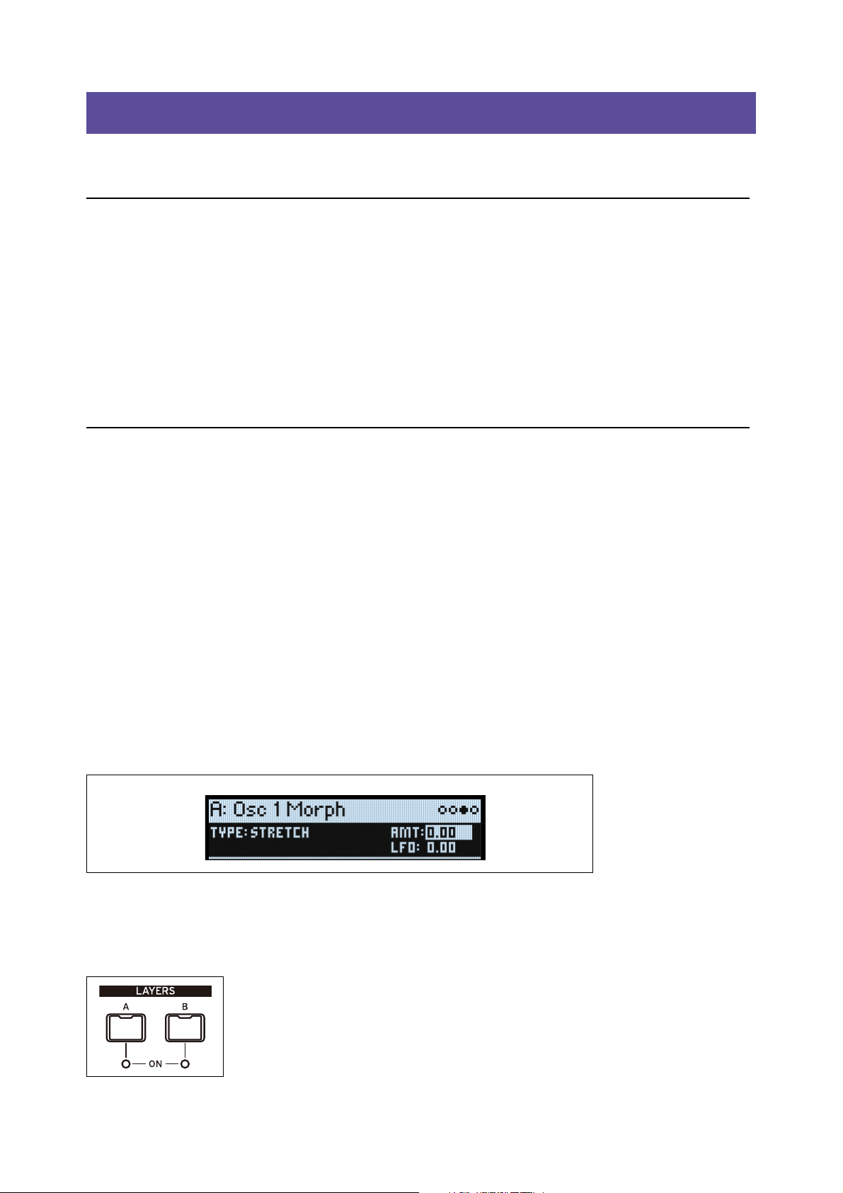
Title bar with selected Layer, Page Name, and Page Indicators
LAYER A/B: Layers contain a Program, an Arpeggiator, and a handful of other settings. The front panel edits one
Layer at a time, as selected by these buttons. To turn a Layer on or off, hold SHIFT and press the Layer’s button, or just
double-press the button.
Most pages on the display apply only to the selected Layer. For these pages, the Layer’s letter (A/B) is shown in the
upper left of the display.
1
Page 7

Getting Started
System
Setup
UTILITY
OCTAVE +/–
MIDI & USB Controllers
MIDI CC
Assign
Global Scale Preferences System Stats About
Kaoss
Physics
Kaoss Physics
Details
Kaoss Physics
Launch
KAOSS
REV SEND
Master
Reverb
Master
Reverb Edit
MASTER
REVERB
EDIT 1/2/3
Master EQ
WET/DRY
Pre FX, Mod
FX, Delay
FX Edit
PRE FX, MOD FX,
DELAY,
EFFECT TYPE
EDIT 1/2/3
Mods Mod List Info
Mod
Processor 1
MOD
Mod
Processor 2
Mod Knobs
MOD KNOBS 1-4
FREQUENCY,
WAVEFORM,
CURVE
LFO
(LFOs) FILTER,
AMP, PITCH,
OSC 1/2 MORPH,
SYNC NOTES
Arpeggiator
ARPEGGIATOR
Perform
PERFORM
Layer
Programs
Velocity
Zones
Keyboard
Zones
Program
Setup
Voice Assign Layer Setup
Performance
Setup
TAP TEMPO
Randomize
Help
Help
Help
Help pages
HELP
WRITE
Write
Name
Write
Metadata
Compare
Delete from
Database
ENTER + WRITE
Lane Lane Step Lane Utility
MASTER, TIMING,
PITCH, SHAPE, SEQ A-D,
NOTE ADVANCE,
LOOP MODE
1-16
(SEQ STEPS)
Motion Seq
Overview
SEQ OVERVIEW
Motion
Sequence
SEQ STEPS
ATTACK, DECAY,
SUSTAIN,
RELEASE
Envelope
Envelope
Curve
Envelope
Trigger
(ENVELOPES)
FILTER, AMP,
OSC 1/2
CURVE (x3)
(AMP ENV) VELOCITY,
(AMP LFO) INTENSITY
Amp
Amp Key
Track
AMP
Osc 1/2 Wave
(OSC 1/2)
WAVE SELECT
Osc 1/2
Position
Osc 1/2
Morph
Osc 1/2
Details
(OSC 1/2)
MORPH,
MORPH TYPE
(OSC 1/2)
POSITION,
A/B BLEND
Mixer &
Sub/Noise
(OSC 1/2)
LEVEL, PAN
(SUB/NOISE)
LEVEL, TYPE
(PITCH LFO)
INTENSITY
Common
Pitch
Pitch Mod
(OSC 1/2)
OCTAVE, TUNE
Osc Pitch
PITCH
CUTOFF,
RESONANCE,
MFILT XFADE,
MFILT PRESET
Multi Filter
(if selected)
Filter Mod
(FILTER)
TYPE
ENV INTENSITY,
(FILTER ENV) VELOCITY,
(FILTER LFO) INTENSITY
Filter Key
Track
Filter
Analyzer
ANALYZER
LEGEND
Button Knob
OLED Display
Page
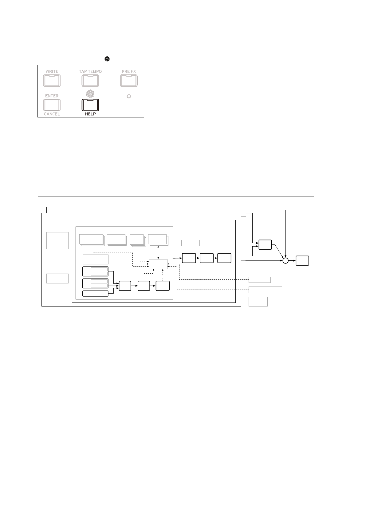
Modwave page map
SHIFT
Hold down SHIFT to use alternative functions for knobs and buttons, labeled in blue text. For one-handed operation,
double-press SHIFT to turn on Shift Hold; press again to turn off.
ENTER for accelerated editing
Hold down ENTER to accelerate editing or scrolling. For example:
• Normally, the VALUE knob works as a “fine” value input when moved slowly, with “coarse” bigger jumps when
moved quickly. To restrict it to “coarse” value changes, hold ENTER while turning VALUE.
•Hold ENTER and press < or > (or turn the VALUE dial) to scroll by a whole page in a list, such as when selecting
Performances, Multisamples, or Mod routings.
Modulation
Most front-panel knobs and on-screen parameters are modulatable. Hold MOD and press > to create a new
modulation routing. When viewing and editing modulations, hold MOD and press < to filter the list. See the Mod List
Info page for an on-screen list of shortcuts.
Mod Knobs
You can use the Mod Knobs in real-time performance, and also save the results as new sounds. The names are shown
on the main PERFORM screen. The values are stored, and can themselves be modulated. The Mod Knobs can control
any number of parameters in any of the Layers.
2
Page 8
Getting Started
Performance
Layer B
Layer A
Arpeggiator
Program A
Voice
Filter Amp
Pre FX Mod FX Delay
Mod Matrix
EQ
+
Voice Assign
Volume
MIDI Channel
MIDI Rx Filters
Key & Vel Zones
Scales
Tempo
Key Track
Key Track
ADSR
2x Mod
Processors
Kaoss Physics
Mod Knobs
ADSR 1-3
ADSR 1-3
ADSR
4x Envelopes
Pitch
Portamento, Slope,
Motion Seq
Osc 2
Wavetable A
Wavetable B
Osc 1
Wavetable A
Wavetable B
Sub/Noise
ADSR
1-3
LFO
ADSR
1-3
ADSR
5x LFOs
Motion Seq
4x Step Seq Lanes
Motion Seq
4x Step Seq Lanes
Motion Seq
4x Step Seq Lanes
Motion Seq
4x Step Seq Lanes
Stereo
Mixer
Reverb
Send A
Send B
Help pages
Hold SHIFT and press the (Randomize) button to bring up a set of pages containing shortcuts and usage tips.
Structure
The modwave plays one Performance at a time.
A Performance has two Layers (A and B), Kaoss Physics, and a master reverb and EQ.
Each Layer contains an Arpeggiator, a Program, and other settings such as MIDI channel, key and velocity zones, etc.
A Program includes two Oscillators (1 and 2), each of which may play one or two Wavetables (A and B) or a single
Multisample, a Sub Oscillator/Noise Generator, a Filter, an Amp, a Motion Sequence, a set of modulators, a
modulation matrix, and three effects: Pre FX, Mod FX, and Delay.
Modwave structure
3
Page 9
Selecting and Playing Sounds
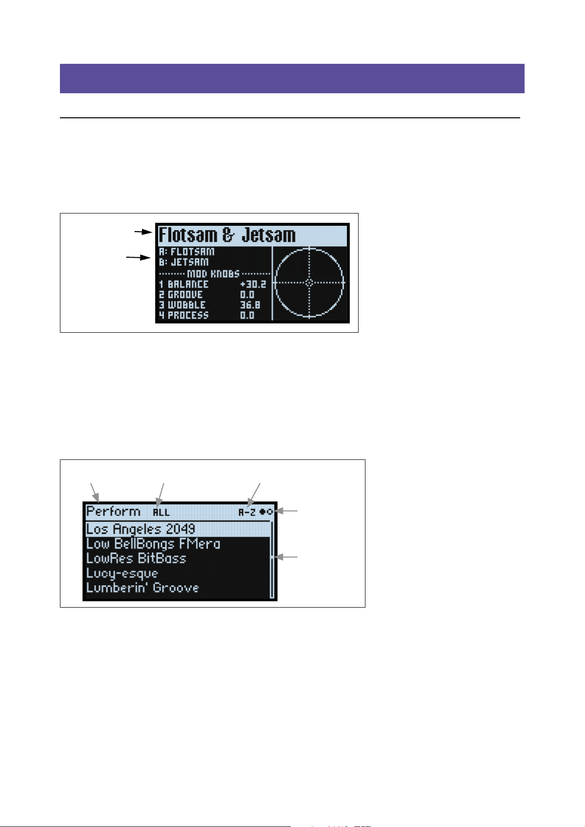
Performance Name
Layer Programs
Category or Collection Sort OrderData Type
Page Indicators
Scroll Bar
Selecting and Playing Sounds
Selecting Sounds
Selecting Performances from the display
1. Press the PERFORM button, and if necessary press it again.
Wherever you are in the system, the second press will always bring up the home page, with the large Performance
name selected.
2. Follow the instructions under “Selecting from lists,” below.
Selecting from lists
Note: These instructions also apply to selecting Set Lists, Performances, Programs, Effects Presets, Motion Sequences,
Wavetables, Multisamples, and Lane Presets.
1. Cursor to the item that you’d like to select.
For this example, we’ll use Performances, continuing from above.
2. Turn the VALUE knob or press ENTER.
A popup appears, showing a list of sounds.
3. Turn the VALUE knob or use < and > to select sounds. Hold ENTER and press < or > to jump by 5.
You can play the sounds as you scroll through the list.
4. When you find a sound that you like, press ENTER again (or SHIFT-ENTER to cancel).
Using Categories
You can filter the list by category or collection. To do so:
1. While the list is onscreen, press CATEGORY buttons 2 (BASS) to 16 (USER) to show only a specific category
2. To show all sounds again, press button 1 (ALL).
The category names on the front panel apply to Performances, Programs, and Multisamples; for all other types of data
(Wavetables, Motion Sequences, etc.), the buttons select the first 15 Categories in the list.
of sounds.
4
Page 10
Selecting and Playing Sounds
You can also show the list of categories on the display. To do so:
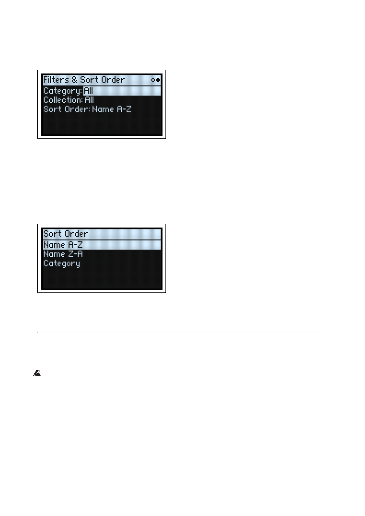
1. In the list popup, hold SHIFT and press > (for PAGE+).
The Filters & Sort Order page appears.
2. Select the Category or Collection parameter, and turn the VALUE knob or press ENTER.
The Category or Collection Select popup appears. The lists will vary depending on the data type.
3. Select the desired Category or Collection, and press ENTER.
The display returns to the Performance Select popup, showing only sounds in the selected Category or Collection.
Using Sort Order
You can change the order in which sounds appear in the list. To do so:
1. In the list popup, press PAGE+.
The Filters & Sort Order page appears.
2. Select Sort Order, and turn the VALUE knob or press ENTER.
3. Choose the desired order.
You can choose from alphabetical (A-Z), reverse alphabetical (Z-A), or Category (sorted alphabetically within each
Category).
Using Set Lists
Set Lists let you group and order Performances for gigs or projects. A Set List has 64 Slots, arranged into four banks AD, corresponding to MIDI Program Change messages 1-64.
Important: Set Lists don’t contain separate copies of their sounds; they just point to Performances stored in the
database.
To select sounds in the current Set List:
1. Press the SET LIST button, so that it is lit.
2. To select sounds in the current bank, press buttons 1-16.
3. To select from a different bank, first hold either SHIFT or SET LIST and then press 1/2/3/4 to select the bank.
Buttons 1-16 will then blink; press one to select a sound in the new bank.
5
Page 11
Selecting and Playing Sounds
If you select a sound using the display, buttons 1-16 will go dark. To return to the Set List, just press one of the buttons
again.
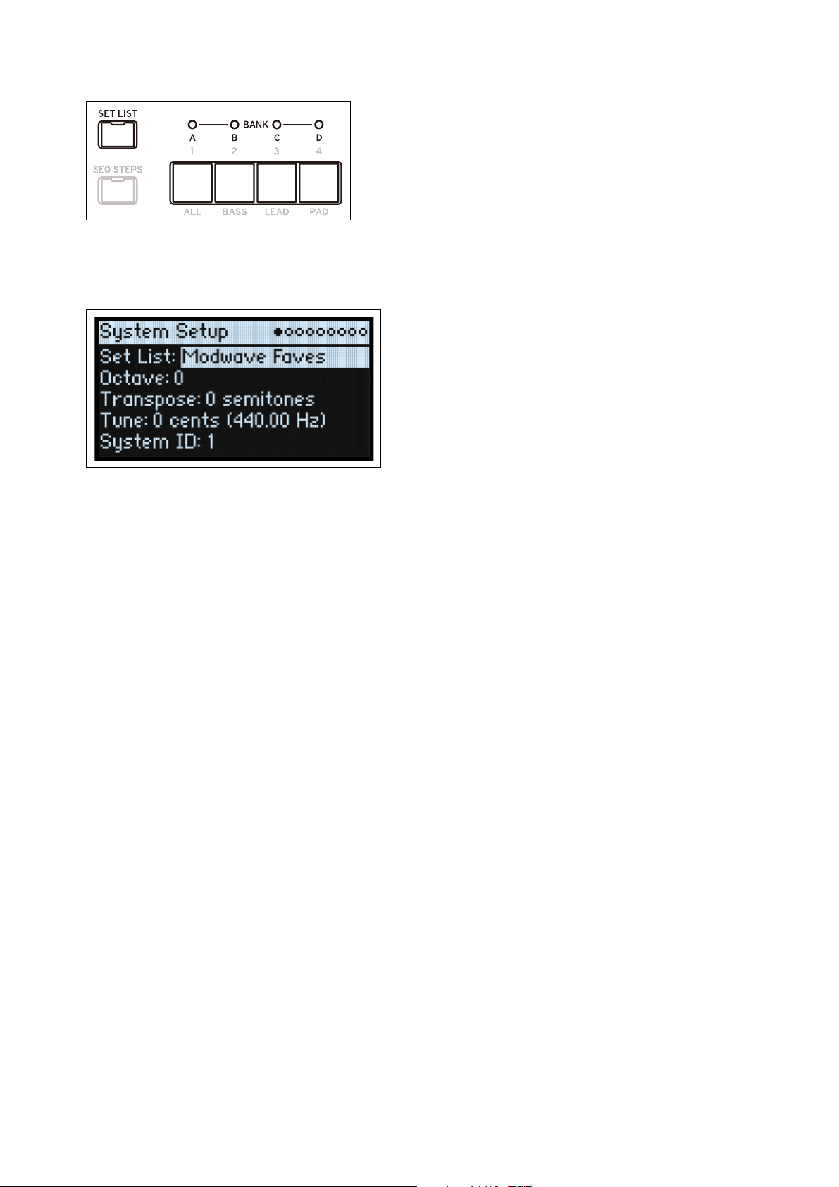
You can store many different Set Lists, and switch between them as desired. To select a different Set List:
1. Press UTILITY twice, to go to the System Setup page.
2. Select the Set List parameter, and press ENTER or turn the VALUE knob.
From this point, selecting Set Lists works just like selecting Performances, as described above.
Assigning a Performance to a Set List Slot
1. Select the Performance that you’d like to assign.
2. Press the SET LIST button, so that it is lit.
3. Hold WRITE and press the Slot to which you’d like to save.
The Write page appears, with that Slot already selected. To change the Slot, hold WRITE and press a different Slot
button.
4. Press WRITE, and then ENTER to confirm.
The Set List will also be saved. If the Performance has been edited, you’ll be prompted to save it too.
Assigning to a Slot in a different bank
While you’re on the Write page, you can also select a Slot from a different bank (for instance, if you’re copying a
Performance to a different Slot):
1. Hold WRITE and SHIFT (or, if you prefer, WRITE and SET LIST), and press button 1-4 for the desired Bank.
2. Release WRITE and SHIFT.
3. Proceed to Step 3 above.
6
Page 12
Basic Editing
Performance Name
Kaoss Physics
Layer Programs
Mod Knob
Names & Values
Basic Editing
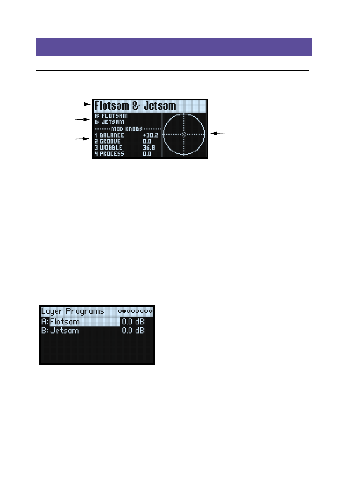
Home Page (PERFORM)
This is the modwave’s main page, where you can select Performances, set the Programs for the two Layers, see the Mod
Knob names and values, and view the Kaoss Physics graphic.
Wherever you are in the system, pressing PERFORM twice in row always returns here, with the Performance name
selected.
Normally, using Mod Knobs takes you to the related pages in the display. The home page is an exception, so that you
can use the Mod Knobs while browsing through Performances.
The home page is also the only one on which the Page Indicators do not appear. Press PAGE+ to go to the Layer
Programs page.
KAOSS Physics display
This shows the Kaoss Physics environment, which models a ball rolling on a surface. You can start the ball by flicking a
finger on the x-y pad, or launch the ball automatically using a trigger source. You can also directly control the ball by
holding your finger on the pad. The position of the ball produces several modulation signals, which can control any
modulatable parameters. For more information, see “Kaoss Physics” on page 45.
Layer Programs
This page shows the Program selection and Volume for each Layer.
A, B (Programs A, B)
[List of Programs]
This selects the Program for the Layer.
(Volume A, B)
[-Inf, -84.9…+6.0 dB]
This controls the volume of the Layer (duplicating the Layer Setup page’s Volume parameter). This is saved in the
Performance, instead of the Program—so it’s a good choice when balancing levels between Layers.
7
Page 13
Basic Editing
Fade-in/
Fade-out
Fade-in/
Fade-out
C8
A0
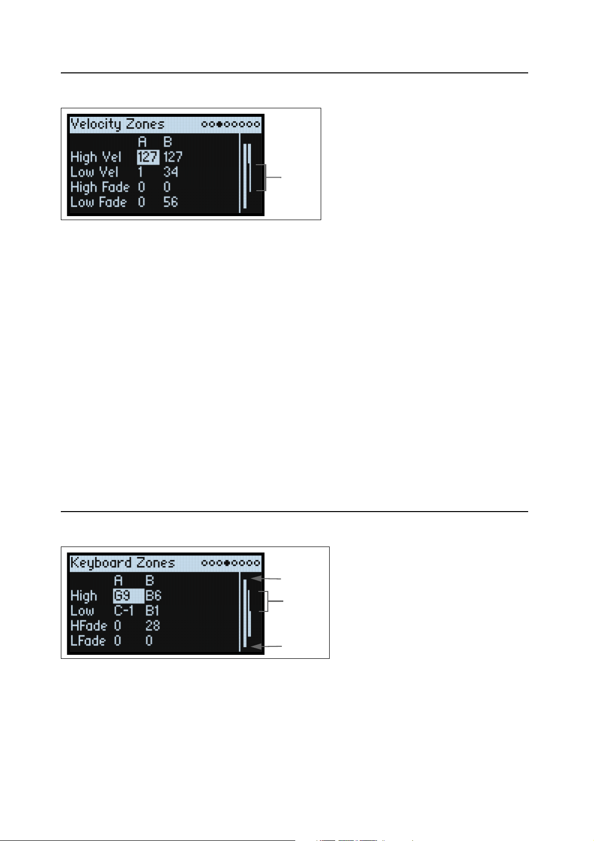
Velocity Zones
Shortcut: Pressing a LAYER button switches to the current parameter in the selected Layer's column.
High Vel (A, B), Low Vel (A, B)
[1…127]
These set the highest and lowest velocities on which the Layer will sound.
High Fade (A, B)
[0…126]
0: The High Vel acts as a hard split, with full volume on one side and silence on the other.
1…126: This lets you create a velocity crossfade. As velocity approaches the High Vel, the volume fades out gradually.
High Fade sets the velocity range over which the fade-out occurs, working inwards from the High Vel.
Low Fade (A, B)
See “High Fade (A, B),” above.
Setting values from the keyboard
You can set velocities and note numbers directly from the keyboard, or via MIDI. This applies throughout the
modwave. To do so:
1. Select the velocity or note number parameter you’d like to edit.
2. Press and hold the ENTER button.
3. Play a note on the keyboard to set the parameter.
4. Release the ENTER button.
Keyboard Zones
Shortcut: Pressing a LAYER button switches to the current parameter in the selected Layer's column.
High (A, B), Low (A, B)
[C-1…G9]
These set the highest and lowest notes on which the Layer will sound.
Note: The graphic shows only the standard range of 88 notes.
8
Page 14
Basic Editing
HFade (High Fade A, B)
[0…127]
0: The High key acts as a hard split, with full volume on one side and silence on the other.
1…127: This allows you to create a keyboard crossfade. As the notes approach the High key, the volume will fade out
gradually. This sets the number of semitones over which the fade-out occurs, working inwards from the High key.
LFade (Low Fade A, B)
[0…127]
See “HFade (High Fade A, B),” above.
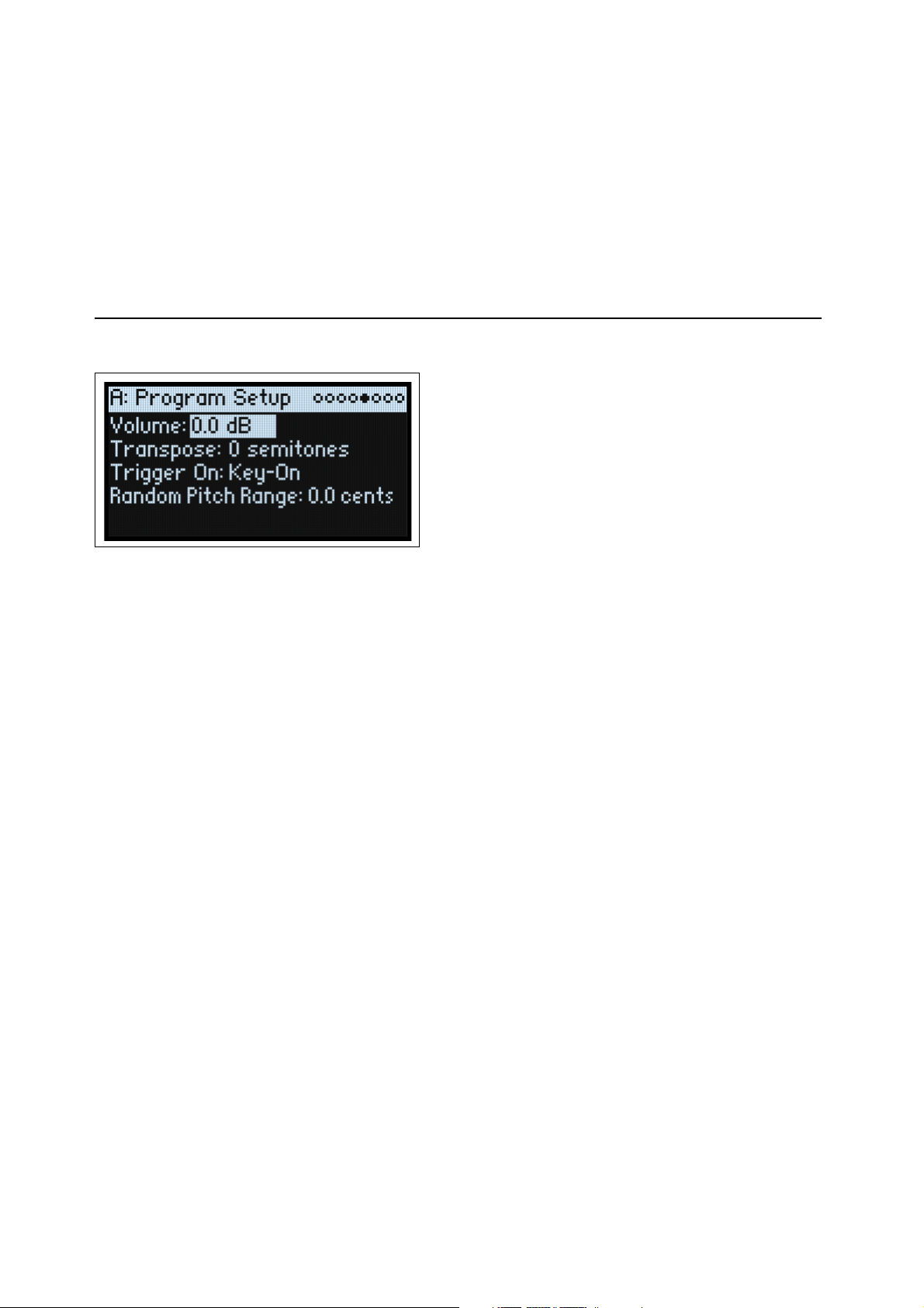
Program Setup
The settings on this page are stored with the Program, if the Program is written separately.
Volume
[-Inf, -84.9…0.0 dB]
This controls the overall volume of the Program. Unlike Layer Volume, it’s stored with the Program. Use this to
balance the Program’s default volume with respect to other Programs.
Transpose
[-60…+60 semitones]
This transposes the Program by up to 5 octaves, up or down, in semitones.
Trigger On
[Key-On, Key-Off]
Key-On: This is the default setting, in which the Program is played when a key is pressed.
Key-Off: The Program will play as soon as you release the key. You can use this to create the “click” heard when a
harpsichord note is released, for instance. In general, when using Key-Off it’s also best to set the Amp Envelope Sustain
to 0.
Random Pitch Range
[0.0…50.0 cents]
This parameter creates random variations in pitch for each note. At the default of 0.0, pitch will be completely stable;
higher values create more randomization. This can be helpful for simulating instruments that have natural pitch
instabilities, such as analog synths, tape-loop keyboards, or acoustic instruments.
9
Page 15
Basic Editing
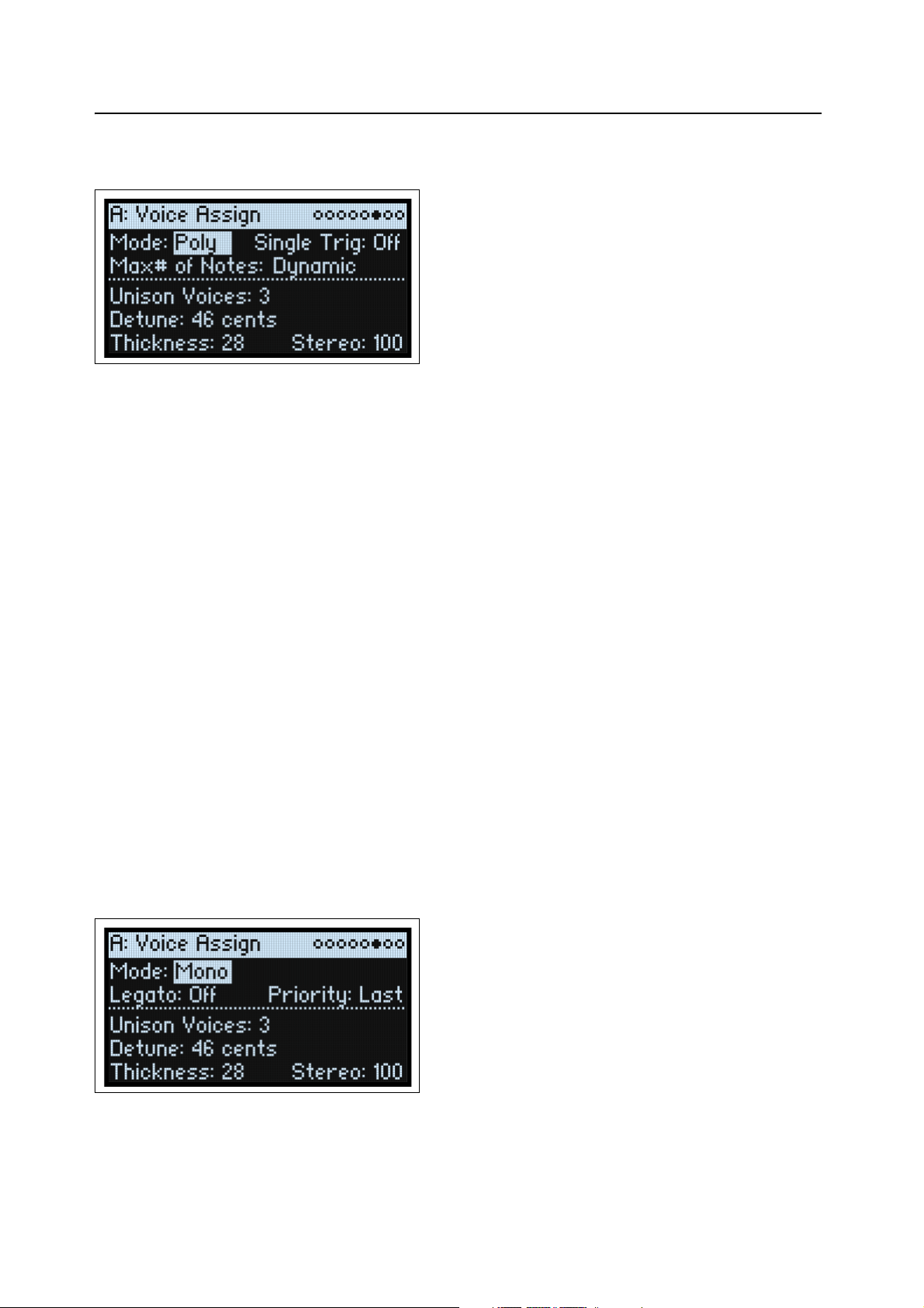
Voice Assign
Mode = Poly
The settings on this page are stored with the Program, if the Program is written separately.
(Voice Assign) Mode
[Poly, Mono]
This selects the basic voice allocation mode. Depending on which one you select, various other options will appear,
such as Single Trig (Poly mode only) and Unison (Mono mode only).
Poly: The Program will play polyphonically, allowing you play chords.
Mono: The Program will play monophonically, producing only one note at a time.
Single Trigger
[Off, On]
Single Trigger is available when Voice Assign Mode is set to Poly.
On: When you play the same note repeatedly, the previous note will be silenced before the next note is sounded, so that
the two do not overlap.
Off: When you play the same note repeatedly, the notes will overlap.
Max # of Notes
[Dynamic, 1…32]
Max # of Notes is available when Voice Assign Mode is set to Poly.
Dynamic is the default. With this setting, you can play as many notes as the system allows.
1-32 limits the number of notes played by the Program. Voices will be allocated dynamically up to this maximum. You
can use this to:
• Model the voice-leading of vintage synthesizers
• Control the resources required by individual Programs
This setting does not limit the Unison Voices parameter. For instance, if Max # of Notes is set to 6, and Unison Voices
is set to 3, you can play up to 6 notes, each with 3 Unison voices.
Mode = Mono
Mono Legato
[Off, On]
Mono Legato is available when Voice Assign Mode is set to Mono.
Legato means to play in a smooth, connected way; the next note is played before the last note is released.
10
Page 16
Basic Editing
On: The first note in a legato phrase will sound normally; subsequent notes in the phrase will sound smoother (for
instance, envelopes will continue instead of restarting).
Off: Legato playing will produce the same sound as detached playing.
Priority
[Low, High, Last]
Priority is available when Voice Assign Mode is set to Mono.
This determines what happens when more than one note is being held down.
Low: The lowest note will sound. Many vintage monophonic analog synths work this way.
High: The highest note will sound.
Last: The most recently played note will sound.
Unison Voices
[1…16]
Unison can be used in both Mono and Poly modes.
1: Unison is off, and Stereo Spread and Detune do not apply.
2-16: The Program uses the specified number of more stacked, detuned voices to create a thicker sound.
Detune
[0…200 cents]
This parameter sets the tuning spread for the Unison voices.
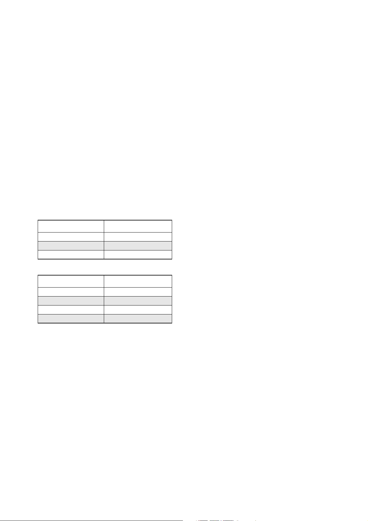
Voices = 3, Detune = 24, Thickness Off
Voices Detune
1–12
2 0
3+12
Voices = 4, Detune = 24, Thickness Off
Voices Detune
1–12
2 –4
3+4
4 +12
Thickness
[0…100]
This parameter controls the character of the detuning for the unison voices.
0: Unison voices are evenly distributed across the Detune range, as shown above.
1…100: Unison voices are detuned asymmetrically. This makes the detuning more complex, and changes the way in
which the pitches beat against one another—like slightly out-of-tune oscillators in a vintage synthesizer. Higher
numbers increase the effect.
Stereo (Spread)
[0…100]
Stereo lets you create a wider stereo field when using Unison. It applies only when Unison Voices is 2 or greater.
11
Page 17
Basic Editing
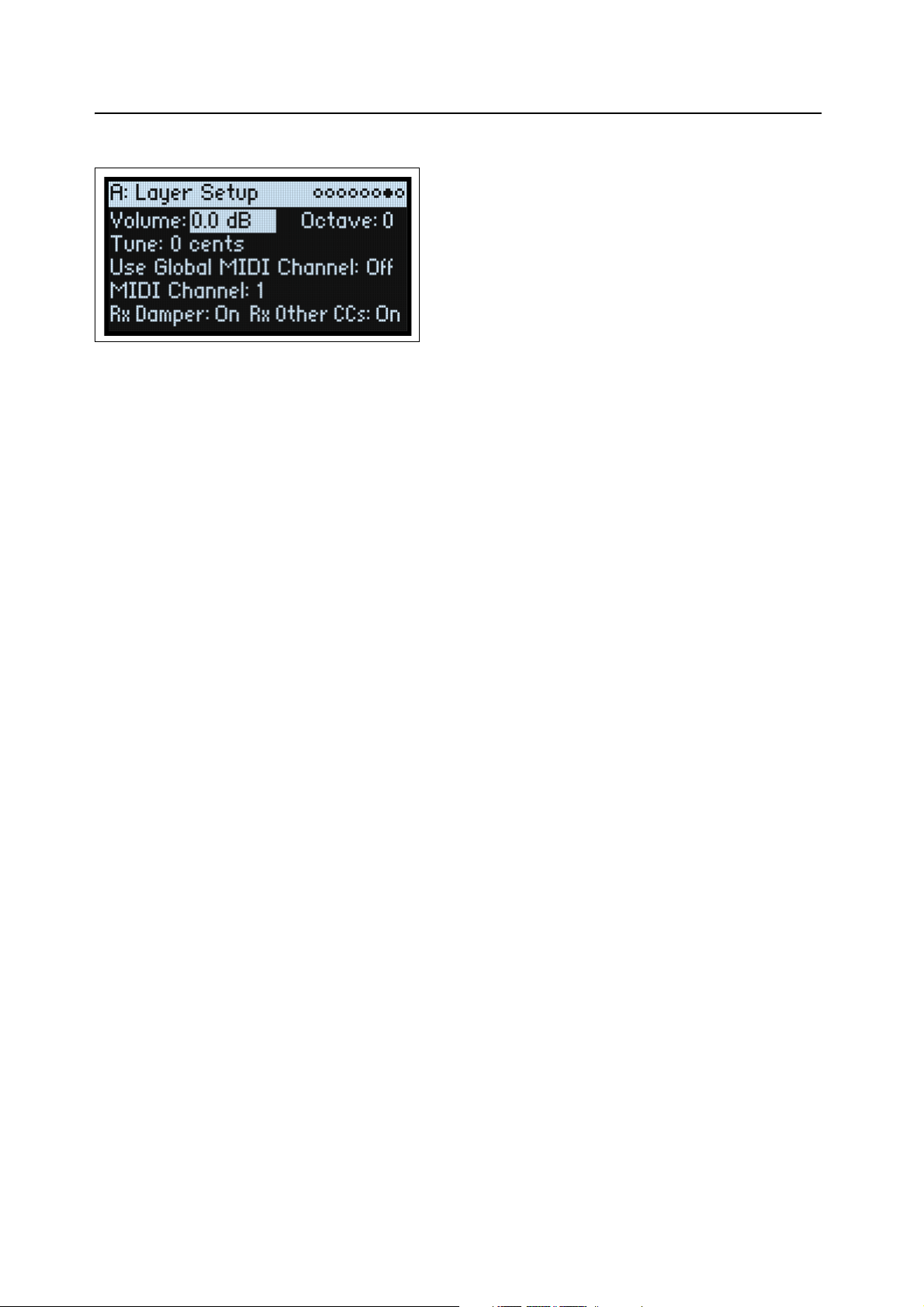
Layer Setup
Volume
[-Inf, -84.9…+6.0 dB]
This controls the volume of the Layer. Note that this is saved in the Performance, but not with the Program—so it’s a
good choice when balancing levels between Layers.
Octave
[-3…+3]
This transposes the Layer by up to 3 octaves, up or down.
Tune
[-100…+100 cents]
This lets you detune the Layer by up to 100 cents (1/100 of a semitone), up or down.
Use Global MIDI Channel
[Off, On]
On: This is the default. The Layer will play from the built-in keyboard, and receive on the Global Channel.
Off: The Layer will receive on the channel specified below, and will not play from the built-in keyboard.
MIDI Channel
[1…16]
This is shown only if Use Global MIDI Channel is Off. It sets the channel on which the Layer will receive MIDI.
Rx Damper
[Off, On]
On: This is the default. The Layer will respond to the connected damper pedal and to MIDI CC#64.
Off: The Layer will ignore both the connected damper pedal and MIDI CC#64.
Rx Other CCs
[Off, On]
On: This is the default. The Layer will respond normally to MIDI CCs.
Off: The Layer will ignore all MIDI CCs (except for CC#64), as well as Aftertouch, Poly Aftertouch, and Pitch Bend.
12
Page 18
Basic Editing
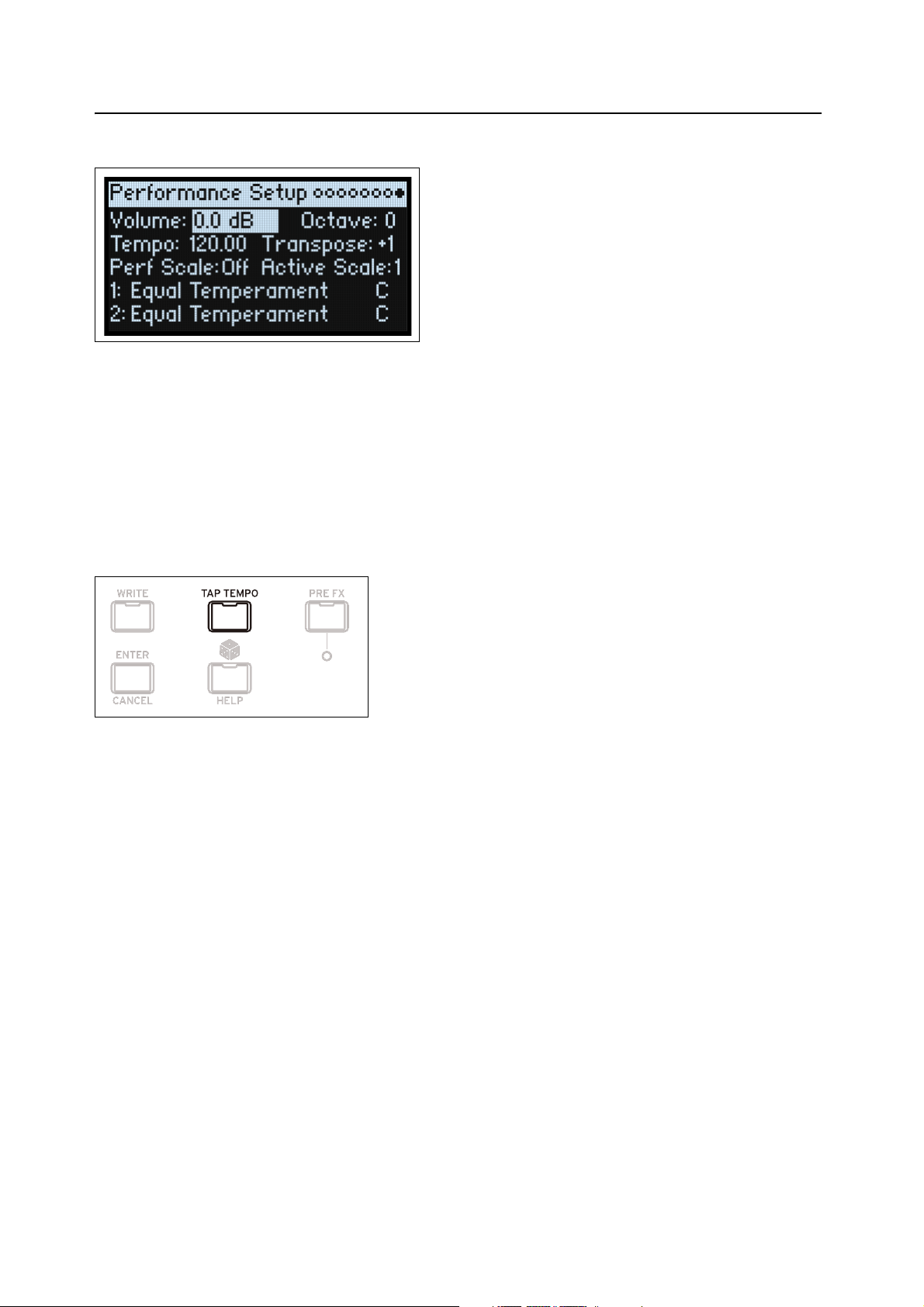
Performance Setup
Volume
[-Inf, -84.9…0.0 dB]
This controls the Performance volume, for balancing levels with other sounds.
Octave
[-2…+2]
This transposes the entire Performance by up to 2 octaves, up or down.
Tempo (TAP TEMPO)
[40…300]
This sets the tempo for the Performance.
Transpose
[-12…+12]
This transposes the entire Performance by up to 12 semitones, up or down.
Perf Scale
[Off, On]
On: The Performance Scale settings, below, are used—unless Global Scale is On, in which case the Global scales are
used instead.
Off: The Performance Scale settings are ignored.
Active Scale, 1 (Scale 1), (Key), 2 (Scale 2), (Key)
For details on the scale parameters, see “Global Scale” on page 94.
13
Page 19
Write
Write
Saving Sounds
The Performance, with its two Layers, contains a complete modwave sound. When selecting, editing, and saving
sounds, Performance are all you need to use. While you can save Programs and presets for Motion Sequences, Motion
Sequence Lanes, and Kaoss Physics, you don’t have to do so: all data is contained in the Performance.
Similarly, when you load any of these other data types into a Performance, a new copy of the data is created in the
Performance. Any edits affect only the local copy inside the Performance, and not the original data. This lets you edit
freely without worrying about changing other sounds.
To save:
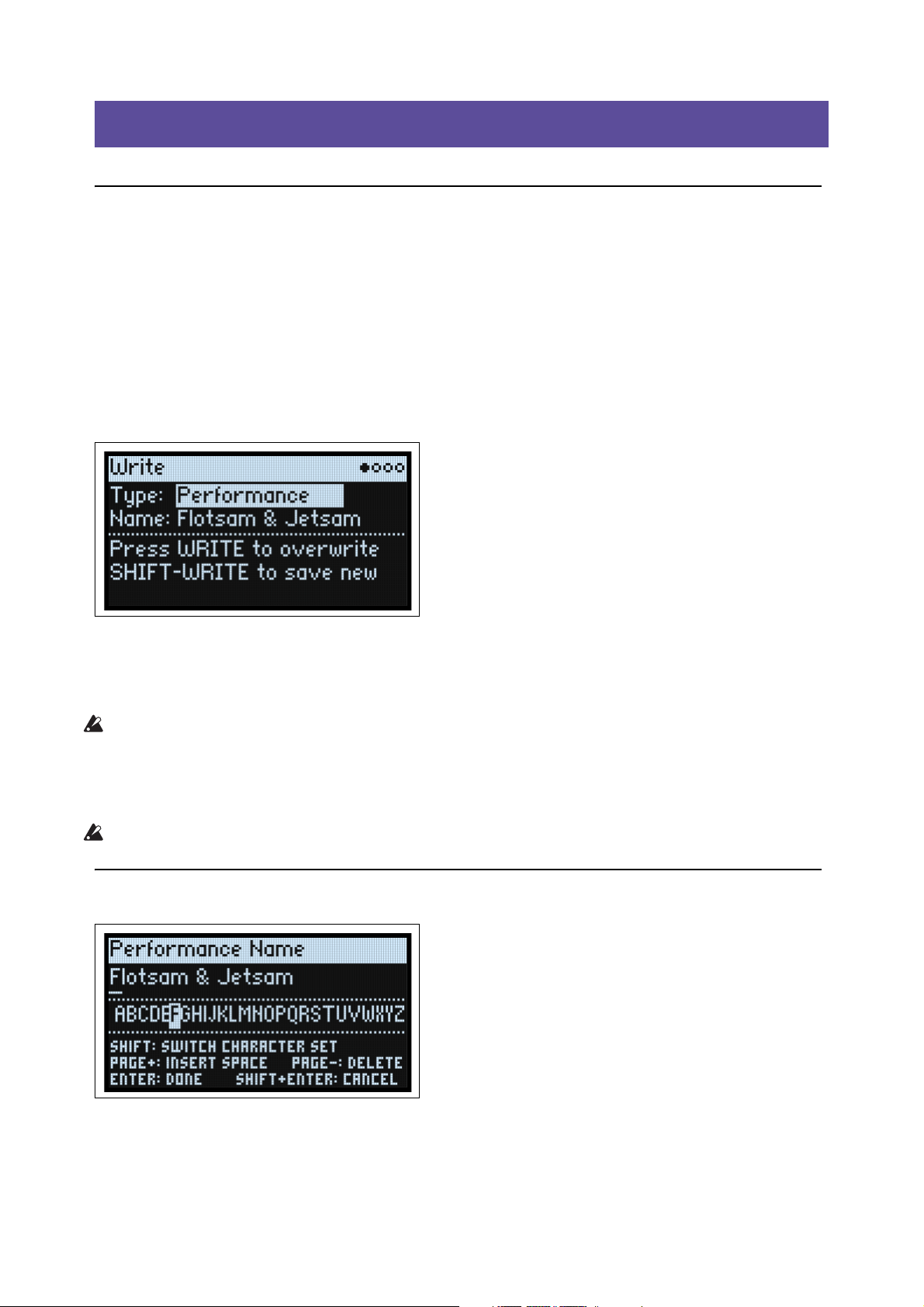
1. Press the WRITE button.
The Write page appears, with the type of data to write shown at the top of the page. By default, this is set to
Performance.
2. To choose a different data type, hold WRITE and press a button such as LAYER A/B or SEQ STEPS, or set the
Type manually in the display.
3. Optionally, edit the name and/or Categories before proceeding.
For more details, see “Editing names” on page 15 and “Write Metadata” on page 15.
Important: changing the name does not automatically make a new copy of the sound!
4. To overwrite the existing sound, press WRITE. To make a new copy and leave the existing sound unchanged,
press SHIFT-WRITE.
5. Press ENTER to confirm, or SHIFT-ENTER to cancel.
Factory sounds may be write-protected, in which case only “save new” is available.
Never turn off the power while data is being saved. Doing so may destroy the internal data.
Name
Note: you can name Programs, Motion Sequences, Lanes, and Kaoss Physics Presets without writing them separately.
As long as you save the enclosing Performance, the new name will be saved.
14
Page 20
Write
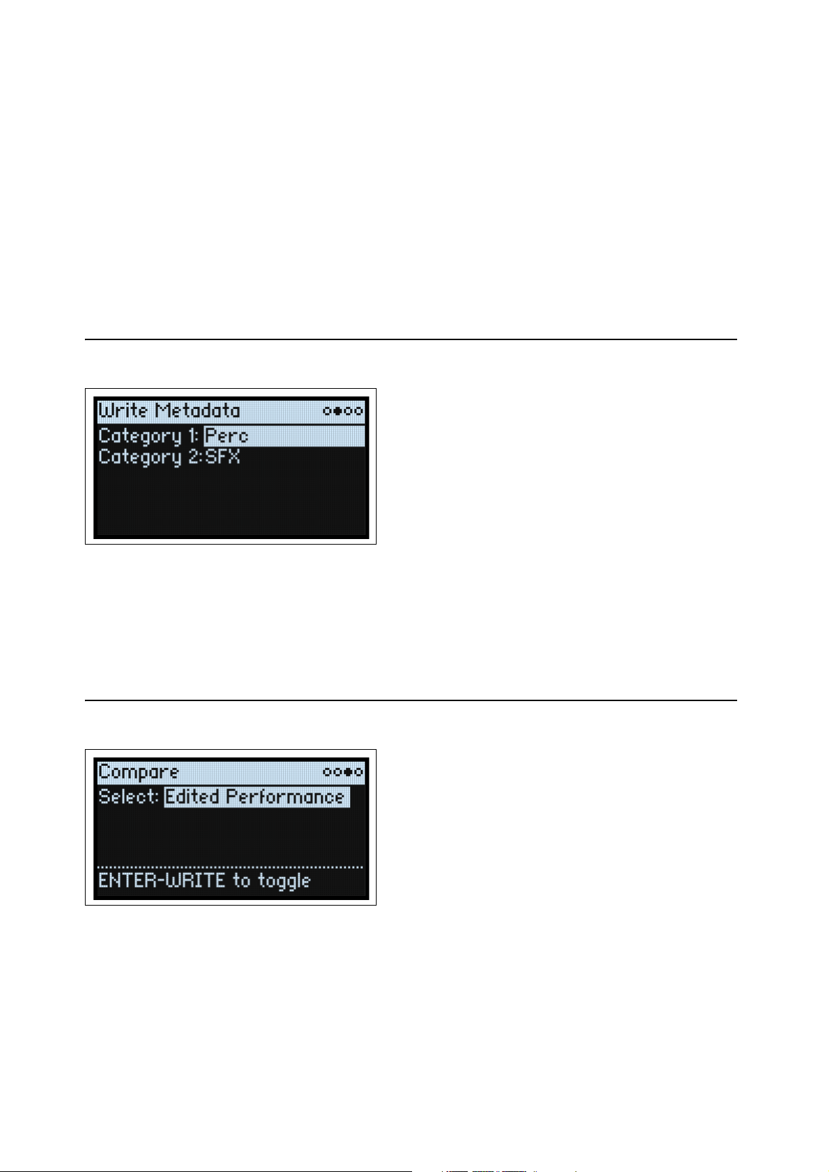
Editing names
1. On the Write page, select the Name.
2. Press ENTER, or turn the VALUE dial.
The Name page appears.
3. Use the cursor buttons to move back and forth in the text, and use VALUE to select a character from the set
shown below.
Names can be up to 24 characters long.
4. Press SHIFT to toggle between A-Z, a-z, numbers, and symbols.
5. Hold SHIFT and press > (PAGE+) to insert a space.
6. Hold SHIFT and press < (PAGE-) to delete the previous character.
7. When you’ve finished entering text, press ENTER to return to the previous page, or SHIFT-ENTER to cancel.
Write Metadata
This shows the Categories for the item shown on the Write page.
Note: When Type is set to Set List Slot, this page is not available.
Category 1/2
[List of Categories]
Each object type—Performances, Programs, etc.—has its own list of Categories. You can create new Categories using
the Editor Librarian software, if desired. Note that only the first 15 Categories are mapped to the front-panel buttons.
Compare
Select
[Saved Performance, Edited Performance]
Saved Performance: The saved version of the Performance will be heard.
Edited Performance: The edited version of the Performance will be heard. If the Performance has not been edited, this
is not available.
15
Page 21
Write
Using Compare
To use compare:
1. Hold ENTER and press WRITE.
The Compare page will appear.
2. Hold ENTER and press WRITE, again, to toggle between the saved and edited versions of the Performance.
When you change from Edited Performance to Saved Performance, the edited version is stored in a buffer, and the
Performance reverts to the version saved in the database. You can toggle back and forth between the two as many times
as you like.
If you change to Saved Performance and then make any edits, the next time you go to the Compare page Select will
be set to Edited Performance, and the previously buffered “Edited Performance” will be lost.
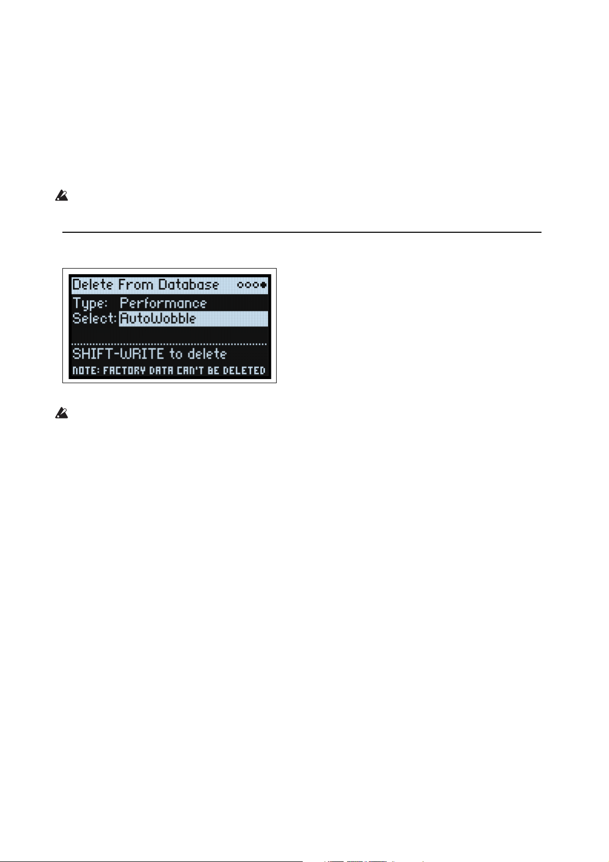
Delete from Database
This page lets you delete user-created items from the database.
Note: Factory data cannot be deleted.
Using Delete
To delete an item from the database:
1. Set the Type as desired.
2. Cursor to Select, and press ENTER.
The selection popup appears.
3. Select a user-created item from the list. Optionally, use PAGE+ to change the filters or sort order.
4. Press ENTER to confirm the selection and close the popup.
5. Hold SHIFT and press WRITE to delete the selected item.
A confirmation dialog will appear.
6. Press ENTER to confirm, or any other key to cancel.
16
Page 22
Wavetable Osc
Wavetable Osc
Overview
Osc 1 and Osc 2 can each play either a single Wavetable, a modulatable blend of two Wavetables, or a Multisample.
The modwave ships with over 200 Wavetables, and you can also import your own via the Sound Librarian software.
The sound of the Wavetables can be changed in different ways. Wavetable Modifiers change the way that the tables are
generated at load time, resulting in subtle to extreme changes in timbre. Morph Types change the way that the
Wavetables are played, and can be modulated in real-time from Envelopes, LFOs, and so on.
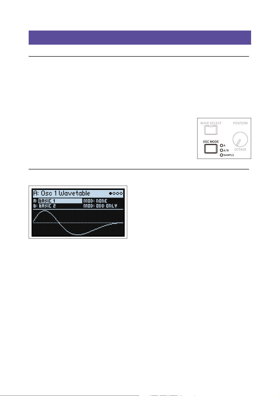
Oscillator Mode (OSC MODE)
[A, A/B, Sample]
This three-way switch on the front panel controls the basic capabilities of the Oscillator.
A: The Oscillator will play a single Wavetable.
A/B: The Oscillator will play a blend of two Wavetables, A and B. A/B BLEND lets you
control the balance between the two. Use this to combine characteristics of two different
Wavetables (such as a pure-sounding table and a buzzy-sounding one), or the same
Wavetable processed by two different Wavetable Modifiers.
Sample: The Oscillator will play a Multisample.
Osc 1 Waveform
Modes A and A/B
A (Wavetable A) (WAVE SELECT)
[List of Wavetables]
This appears if Oscillator Mode is set to A or A/B. Select the parameter and then either turn the VALUE knob or press
ENTER to bring up the Wavetable Select popup, which shows all of the Wavetables installed on the instrument. For
details on sorting and filtering the list of Wavetables, see “Selecting from lists” on page 4.
Listening to the Wavetables
When auditioning Wavetables, play lower-pitched notes. The lower the pitch, the more clearly you’ll hear all of the
high harmonics.
By default, the OSC 1 and OSC 2 Envelopes modulate Position; this sweeps the Wavetables for their respective
oscillators. Attack sweeps forward in the Wavetable, and Decay sweeps backwards; the Sustain level determines the
resting point. Try both fast and slow envelope times for both Attack and Decay—even 10 or more seconds may be
useful for particularly complex Wavetables!
Adjust the amount of modulation using Env Intensity (SHIFT-VELOCITY). Sometimes, you may want the intensity
to be at its maximum; other times, especially with more complex Wavetables, much smaller amounts of modulation
may be better.
Some Wavetables may be optimized for use with an LFO, instead. Try using a Triangle-shaped LFO to modulate
Position.
17
Page 23

Wavetable Osc
MOD (Wavetable A Modifier)
Each waveform in a Wavetable is stored as a single 32-bit floating-point table with 2048 samples, referred to below as
the “base table.” This corresponds to a pitch of about 25 Hz. Tables for higher pitches are generated when the
Wavetable is loaded. The Wavetable Modifier options let you change how these tables are generated, creating differentsounding variations of the stored data.
None: The Wavetable is loaded without alteration.
Odd Only: This preserves only the odd harmonics. All even harmonics (2, 4, 6, etc.) are removed.
Even Only: This preserves the fundamental and all the even harmonics. All odd harmonics (3,5,7, etc.) are removed.
The result can sound like a sine wave at the fundamental plus a waveform an octave above that.
Skip Every 3: This removes every third harmonic (3, 6, 9, etc.).
Odd + Clip: This combines Odd Only and Hard Clip, producing a brighter version of the Wavetable with increased
overtones and only odd harmonics.
Even + Clip: This combines Even Only and Hard Clip, producing a brighter version of the Wavetable with increased
overtones with only even harmonics.
Skip + Clip: This combines Skip Every 3 and Hard Clip, producing a brighter version of the Wavetable with increased
overtones and with every third harmonic removed.
Low 20: This removes all but the lowest 20 harmonics.
Low 12: This removes all but the lowest 12 harmonics.
Organ-ize: This emphasizes the harmonics that correspond to organ drawbars: 1 (8’), 2 (4’), 3 (2
1
/3’), and 8 (1’). The other harmonics are still present, but greatly reduced. The result is drawbar organ sounds with
6(1
“stops” based on the Wavetable.
Vintage 8: This quantizes to 8 bits and disables band-limiting for all but the highest notes, resulting in a brighter sound
with higher noise and significant aliasing.
Vintage 12: This quantizes to 12 bits and disables band-limiting for all but the highest notes, resulting in a brighter
sound with moderate amounts of noise and aliasing.
4 Steps: Quantizes the base table to 2 bits, using band-limiting to minimize aliasing (so, you’ll notice that the displayed
waveform is smoother than a simple 2-bit waveform).
8 Steps: Quantizes the waveform to 3 bits, similar to 4 Steps, above.
16 Steps: Quantizes the waveform to 4 bits, similar to 4 Steps, above.
Soft Clip: Applies gentle soft clipping to the base table, adding overtones and increasing brightness.
Hard Clip: Applies a gain of 3.0 and then clips the result, for a greater increase in overtones and brightness.
Infinite Clip: Applies a ridiculous amount of gain, then clips the result.
Note that Soft Clip, Hard Clip, and Infinite Clip are very different from applying clipping to the audio output. The
timbre isn’t affected by the oscillator level or the number of voices being played, and the results are band-limited to
avoid harsh tones.
Tilt Up: This reduces the levels of lower harmonics, and increases the levels of higher harmonics, tilted around the 12th
harmonic.
Tilt Up +: Similar to Tilt Up, but more extreme.
Tilt Down: This increases the levels of lower harmonics, and reduces the levels of higher harmonics, tilted around the
12th harmonic.
Tilt Down +: This increases the levels of lower harmonics, and reduces the levels of higher harmonics, tilted around the
8th harmonic.
Low Boost: Boosts the first 5 harmonics.
Low Cut: Reduces the fundamental and first few harmonics.
Low Cut +: Reduces the first 5 harmonics.
Muted: Dramatically lowers the level of all harmonics above the fundamental.
Fade Out: Crossfades successive waves in the Wavetable with 0 so that the waveform fades out to 0 as Position
increases. Use this to create decaying plucked or percussive sounds just by sweeping the Position.
Reverse: Loads the Wavetable’s individual waves in reverse order. This is particularly useful for Wavetables which
sweep from a bright or complex sound on one end to a dark or simple sound on the other.
Gain +3 dB, Gain +6 dB, Gain -3 dB, Gain -6 dB: Increase or decrease gain by the specified amounts. These are
particularly useful for balancing the volume between Wavetables A and B.
2
/3’), 4 (2’), 5 (1 3/5’),
18
Page 24
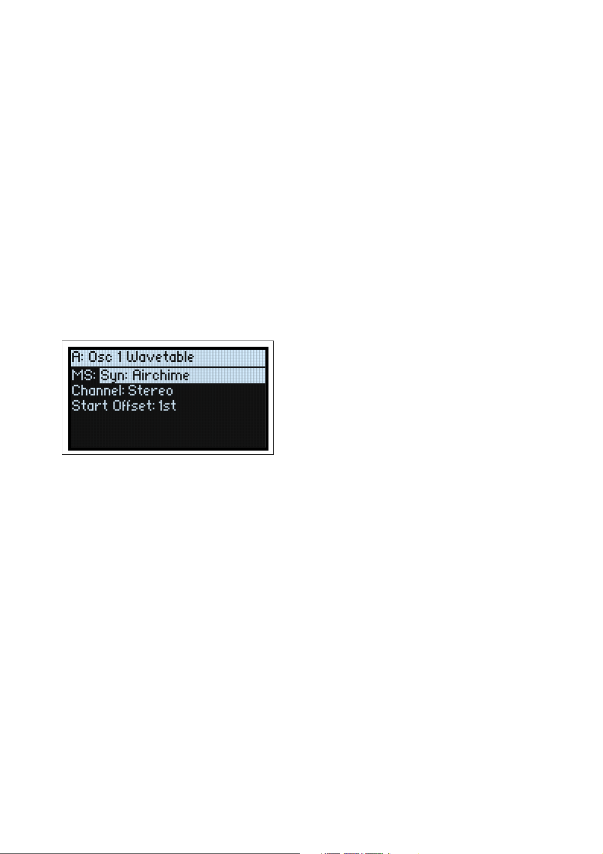
Wavetable Osc
Tip: Fade between modified and original versions of a Wavetable
1. Set Mode to A/B.
2. Select the same Wavetable for both A and B.
3. Make sure that B Offset is set to 0.00.
4. Set Wavetable A Modifier to None.
5. Set Wavetable B Modifier as desired (for instance, Hard Clip).
6. Use A/B BLEND to fade between the normal and modified versions.
With Hard Clip, this will create a sound similar to a low-pass filter. Try modulating A/B BLEND via an Envelope or
LFO! Since Wavetables A and B are phase-locked, you can use this technique to fine-tune the effects of any of the
Modifiers. For example, try using this with any of the Tilt, Boost, or Cut options.
B (Wavetable B) (WAVE SELECT)
[List of Wavetables]
This selects the Wavetable for Wave B; it appears only if Oscillator Mode is set to A/B. A/B BLEND then controls the
mix of Wavetables A and B. Pressing WAVE SELECT toggles between selecting Wavetables A and B.
MOD (Wavetable B Modifier)
This selects the Modifier for Wave B; it appears only if Oscillator Mode is set to A/B. For more information on
Modifiers, see “MOD (Wavetable A Modifier)” on page 18.
Sample Mode
These parameters are shown when Oscillator Mode is set to Sample.
MS (Multisample)
[List of Multisamples]
Select this parameter and then either turn the VALUE knob or press ENTER to bring up the Multisample Select
popup.
Channel
[Stereo, Left, Right, n/a]
This applies to stereo Multisamples only; for mono Multisamples, “n/a” is shown. You can choose whether to use the
original Stereo signal, or only the Left or Right channels (in mono).
S. Offset (Start Offset)
[Off, 1st…8th]
In addition to simply starting playback from the beginning, Multisamples may have up to 8 different pre-programmed
alternate starting points, or “Start Offsets.” These skip part of the beginning of the samples, either to make them more
gentle (for percussive sounds) or to make them start more quickly (for sounds with slow attacks). The number of
available offsets will vary depending on the specific Multisample.
If no alternate start points are available, this will show n/a.
19
Page 25
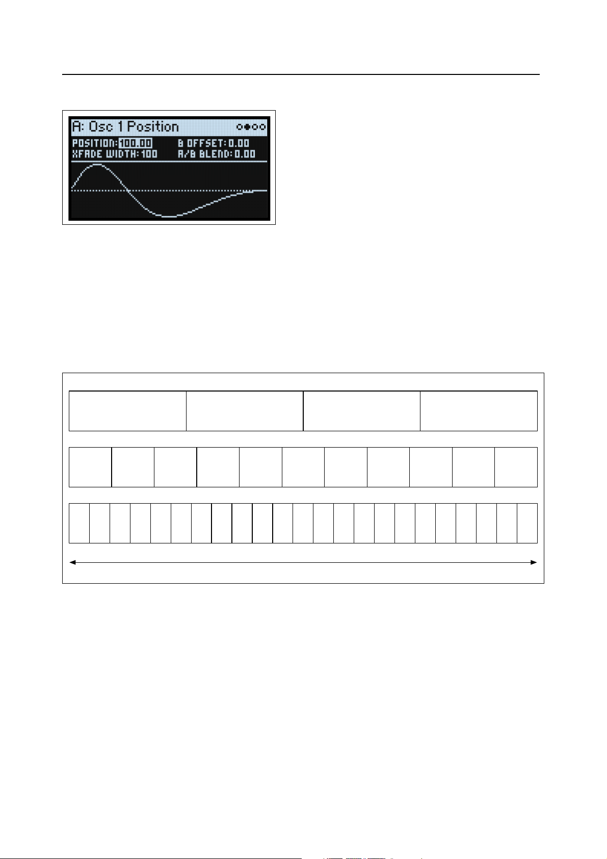
Wavetable Osc
Wavetable with 4 waveforms
Wavetable with 11 waveforms
Wavetable with 23 waveforms
Osc 1/2 Position
Position (POSITION)
[0.00…100.00]
Wavetables contain up to 64 waveforms. Position sweeps through all of the waveforms in the Wavetable. 0.00 always
selects the first waveform, and 100.00 selects the last waveform. The range between these extremes is divided between
the total number of waveforms in the selected Wavetable, as shown below.
Note that when Mode is set to A/B, Wavetables A and B may have different numbers of waveforms. In this case,
Position will divide the range evenly for each Wavetable, just as if they were being used individually. For instance, if A
has four waveforms and B has 23 (see the graphic below), a Position just under 50 will play waveform 2 in A, and
waveform 12 in B.
Position
Wavef orm1Wavef orm2Wavef orm3Wavef orm 4Wavef orm 5Wavef orm 6Wavef orm 7Wavef orm 8Wavef orm 9Wavef orm 10Wavef orm
Wave1Wave2Wave3Wave 4Wave 5Wave 6Wave 7Wave 8Wave 9Wave10Wave 11Wave12Wave13Wave14Wave 15Wave 16Wave 17Wave 18Wave 19Wave 20Wave21Wave 22Wave
0 Position 100
B Offset
[0.00…100.00]
This appears only if Mode is set to A/B. The position of Wavetable B is the sum of Position (above) and B Offset.
A/B Blend (A/B BLEND)
[0.00…100.00]
This appears only if Mode is set to A/B. It controls the balance between Waves A and B.
Xfade Width
[0.00…100.00]
As the Position changes, the Wavetable changes from one waveform to another. When changing between two adjacent
waveforms, the transition can be gradual or immediate. Xfade Width controls the amount of the Position range spent
interpolating between neighboring waveforms vs. the amount playing single waveforms. Note that this does not affect
A/B Blend.
Wavef orm
1
Wavef orm
2
Wavef orm
3
Wavef orm
4
11
23
20
Page 26
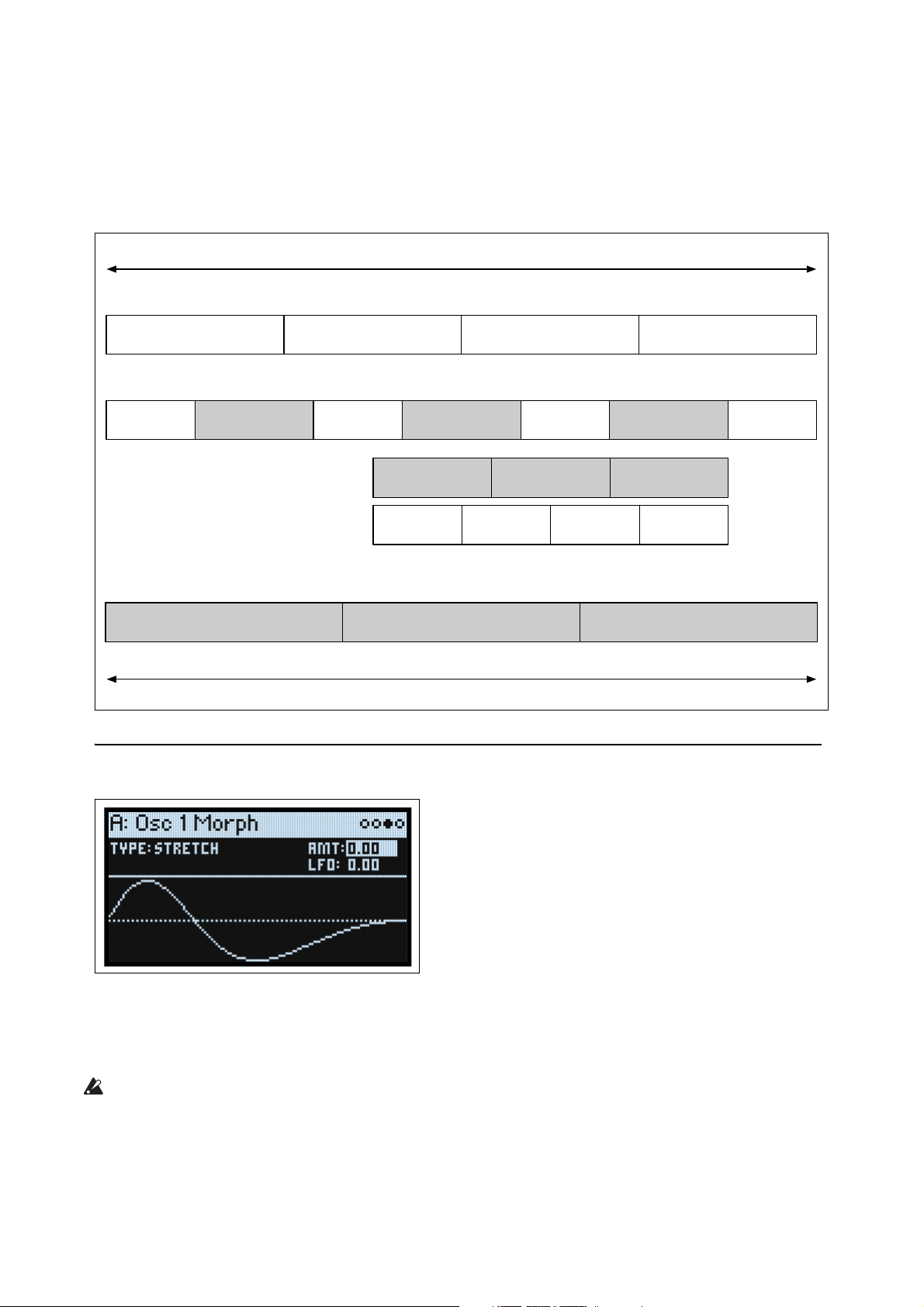
Wavetable Osc
Wavef orm
1
Wavef orm
2
Wavef orm
3
Wavef orm
4
Wavef orm
1
Crossfade 1-2
Wavef orm
2
Crossfade 2-3
Wavef orm
3
Crossfade 3-4
Wavef orm
4
Crossfade 1-2 Crossfade 2-3 Crossfade 3-4
Wavef orm
1
Wavef orm
2
Wavef orm
3
Wavef orm
4
Crossfade 1-2 Crossfade 2-3 Crossfade 3-4
Wavef orm
1
Wavef orm
2
Wavef orm
3
Wavef orm
4
0 Position 100
0 Position 100
Xfade Width = 0.00
Xfade Width = 50.00
Xfade Width = 100.00
When Xfade Width = 50.00, half of the Position
range is taken up by crossfades, and the other
half is taken up by the single waveforms playing
unaltered. Note how the total length of the
three crossfade zones is the same as the total
length of the four single waveform zones.
It may be helpful to think of the Position value range 0-100 as a ribbon, with the Wavetable stretched to fit, regardless
of how many waveforms it contains. Each waveform is a stripe on the ribbon. Xfade Width controls the amount of
blurring between the stripes. A given value for Position will always yield the same output, which will be either a solid
stripe or some amount of blurring between two stripes. When Position changes continuously, as with an envelope or
LFO, this causes crossfades between the waveforms.
Xfade Width
Osc 1/2 Morph
Morph Type (SHIFT-MORPH)
[List of Morph Types]
The Morph Types let you stretch, squeeze, reflect, and otherwise alter the Wavetables in real-time, changing their
timbre and—when modulated—creating additional motion in the sound.
When the Oscillator MODE is set to Sample, the Morph Type options are limited. For Oscillator 1, Morph is
completely unavailable. For Oscillator 2, only the AM and Ring Mod Morph Types are available.
None: The Wavetable is played unaltered.
Sync: The Wavetable is reset by a phantom oscillator, creating the classic sync sound. Morph Amount controls the
frequency of the phantom oscillator.
21
Page 27
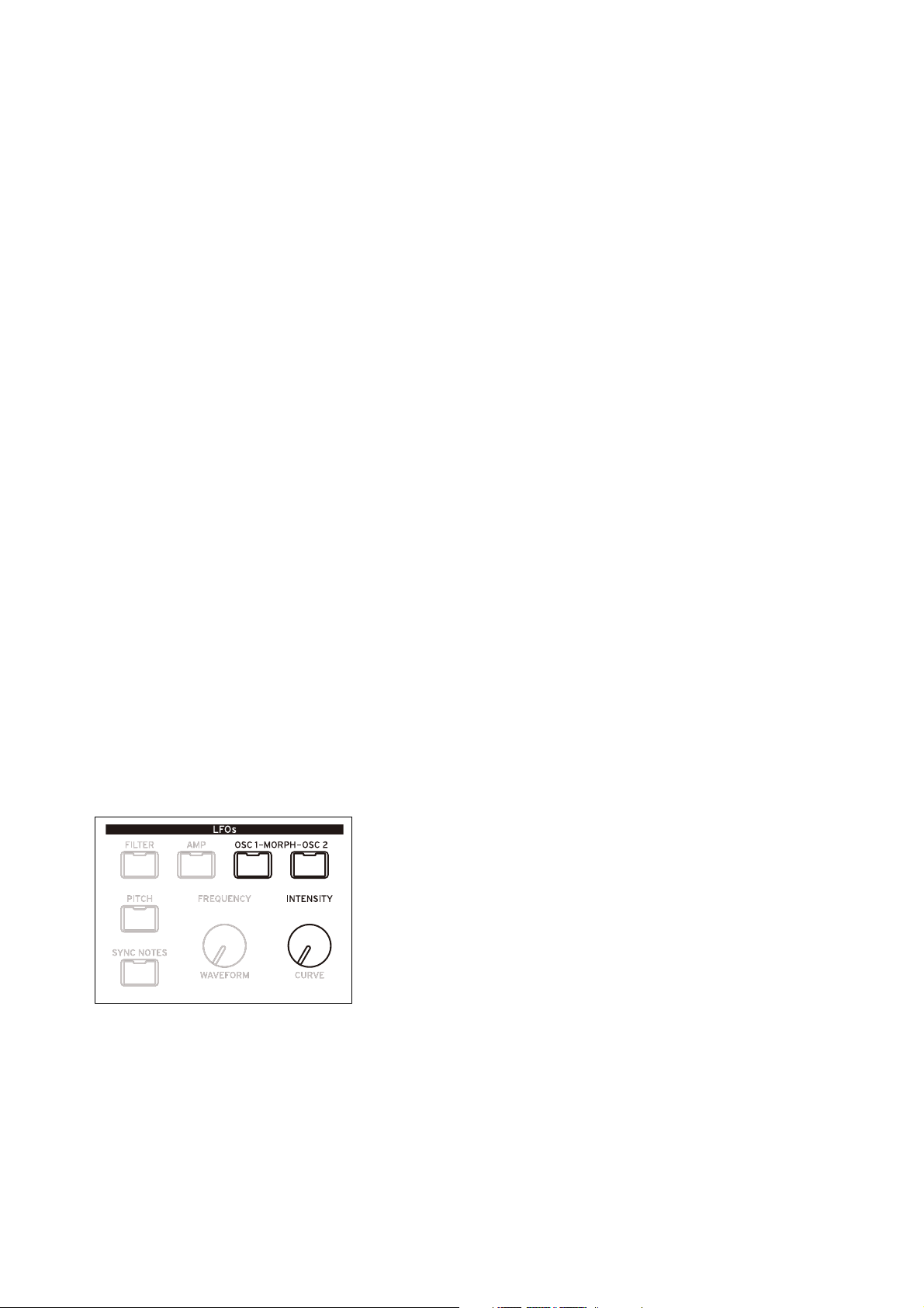
Wavetable Osc
Windowed Sync: Similar to Sync above, but with reduced high frequencies for lower aliasing.
Stretch: The waveform is stretched in one direction and squeezed in the other, creating an effect similar to Pulse Width
Modulation. When Morph Amount is set to 50, the waveform is unaltered.
Flip: This inverts the polarity of a section of the waveform, with the “flip” point determined by Morph Amount.
Mirror: Shrinks the waveform to half its length, and then reflects that half-length waveform around the center as a
mirror image. Morph Amount stretches and squeezes the waveform similar to Stretch, above.
Mirror Stretch: This is similar to Mirror, above, but doubles the Stretch effect.
Narrow: As Morph Amount increases, the waveform is compressed towards the front, with zeros filling the rest of the
duty cycle. The effect is different from Stretch, but also has some similarities to Pulse Width Modulation.
Narrow Stretch: This combines Narrow and Stretch, compressing the waveform’s length while also stretching and
squeezing.
Windowed Narrow: Similar to Narrow above, but with reduced high frequencies for lower aliasing.
W.NarrowStretch: Similar to Narrow Stretch above, but with reduced high frequencies for lower aliasing.
Additional Osc 2 Morph Types
Osc 2 supports all of the Morph Types listed above, and three more: FM, AM, and Ring Mod. For all of these, Oscillator
1 is the modulator, and Oscillator 2 is the carrier. If you’re using Oscillator 1 solely as a modulator, you may wish to set
its Level to 0%.
Note: when using these Morph Types, the waveform graphic will be an approximation. If you’d like to see the exact
results graphically, use the ANALYZER instead (see “Analyzer” on page 26).
FM: Oscillator 1 modulates the frequency of Oscillator 2. Morph Amount controls the amount of frequency
modulation.
AM, or amplitude modulation, includes both ring modulation, as below, and the dry signal from Oscillator 2. Morph
Amount controls the amount of amplitude modulation.
Ring Mod combines the two Oscillators to generate new sideband frequencies based on those inputs. The result can be
everything from subtle brightening to wild, dissonant, gong-like timbres. When the frequencies of Oscillators 1 and 2
are the same, the Ring Modulator produces steady, constant waveforms. When they are detuned, it produces more
movement and overtones. Morph Amount controls the amount of ring modulation.
AMT (Morph Amount) (MORPH)
[0.00…100.00]
This controls the intensity of the Morph process, as described above.
LFO (INTENSITY)
[-100.00…+100.00]
This sets the intensity of the Morph modulation from the Osc 1 LFO (for Osc 1) or the Osc 2 LFO (for Osc 2).
22
Page 28
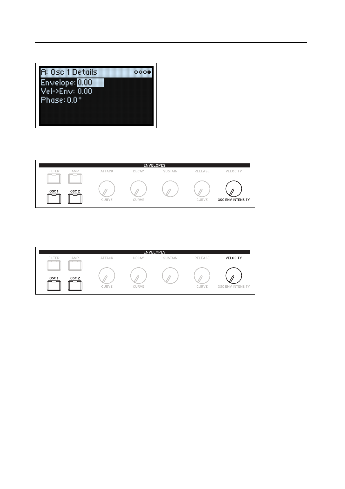
Wavetable Osc
Osc 1/2 Details
Envelope (OSC ENV INTENSITY)
[-100.00…+100.00]
This sets the amount of Position modulation from the Osc 1 Envelope (for Osc 1) or the Osc 2 Envelope (for Osc 2).
Vel->Env (VELOCITY)
[-100.00…+100.00]
This lets you use velocity to scale the amount of Position modulation from the Osc 1 Envelope (for Osc 1) or the Osc 2
Envelope (for Osc 2).
Phase
[-180…+180]
This controls the phase of the waveform at the start of the note. It’s most useful when Oscillators 1 and 2 are not
detuned.
23
Page 29
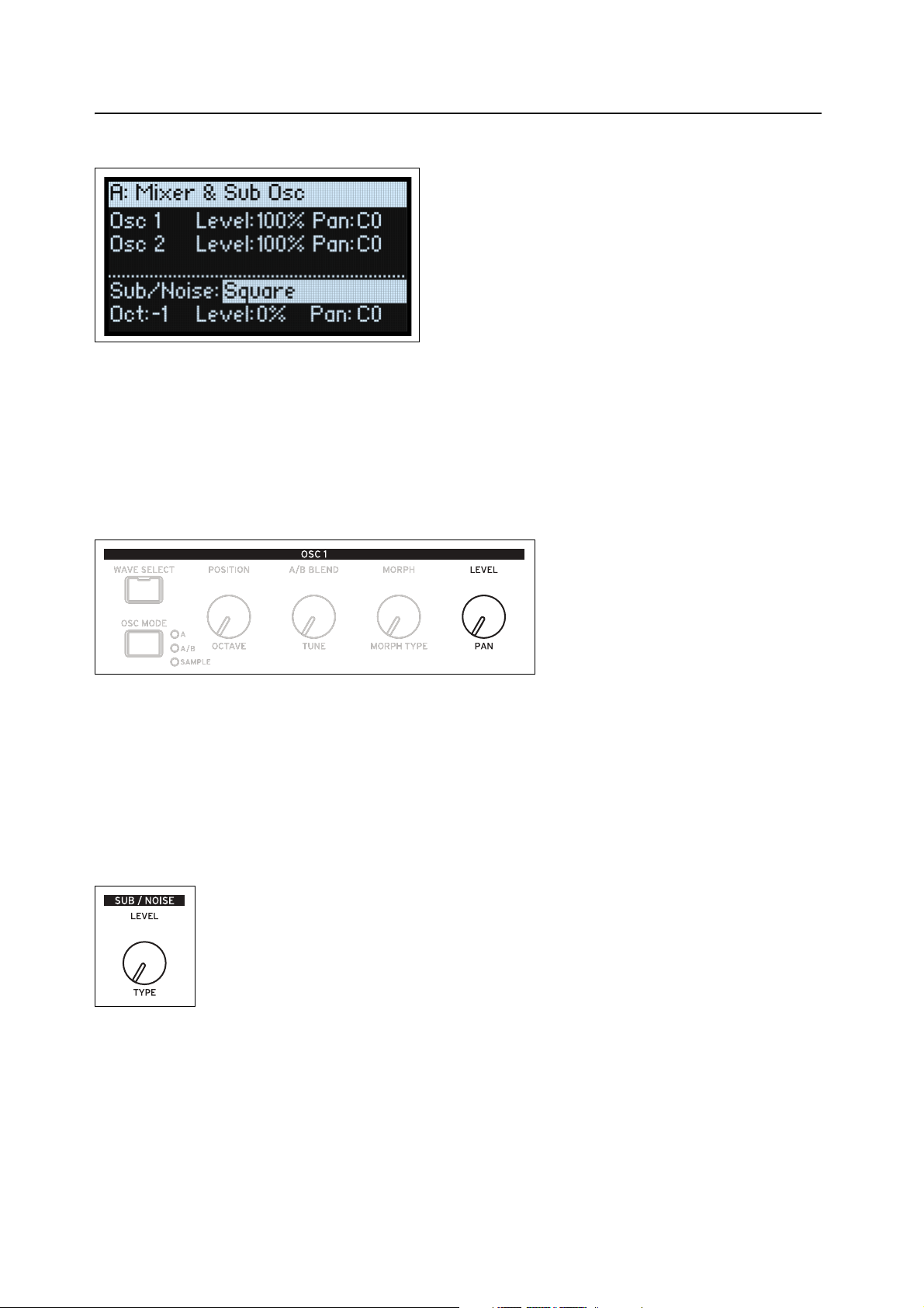
Wavetable Osc
Mixer & Sub Osc
Osc 1
Level (LEVEL)
[0%…100%]
This controls Oscillator 1’s volume.
Pan (SHIFT-LEVEL)
[L100…L1, C0, R1…R100]
This controls Oscillator 1’s stereo position.
Osc 2
Level (LEVEL)
[0%…100%]
Pan (SHIFT-LEVEL)
[L100…L1, C0, R1…R100]
See the descriptions for Osc 1, above.
Sub/Noise
This section can be either a sub oscillator or a noise generator, depending on the selected Sub/Noise Type.
Sub/Noise Type (Sub/Noise) (SHIFT-LEVEL)
[Square, Triangle, White Noise, Filtered Noise, Dark Noise, Speckled Noise, Saturated Noise]
Square, Triangle: These produce the specified waveform at the same pitch as Osc 1, or one or two octaves below.
White Noise: This is classic, full-spectrum white noise.
Filtered Noise: Similar to White Noise, above, but less bright.
Dark Noise: Similar to Filtered Noise, but with significant high-end roll-off.
24
Page 30

Wavetable Osc
Speckled Noise: This is noise with both roll-off and clipping, producing a very aggressive timbre. With additional
lowpass filtering, it can produce sounds reminiscent of thunder and explosions.
Saturated Noise: This uses moderate filtering and saturation to produce a thicker-sounding noise signal.
Oct
[–2, –1, 0]
This applies only when Sub/Noise Type (on the Mixer & Sub Osc page) is set to Square or Triangle. It sets the pitch
offset from Oscillator 1, in octaves. This parameter is duplicated on the Osc Pitch page. Set Octave to -1 or -2 to add
rumbling bass, or to 0 to supplement the fundamental of a thin-sounding Wavetable.
Level (LEVEL)
[0%…100%]
This sets the volume of the Sub/Noise component.
Pan
[L100…L1, C0, R1…R100]
This sets the stereo position of the Sub/Noise component.
25
Page 31

Analyzer
Analyzer
The Analyzer shows a real-time oscilloscope view of the full, polyphonic modwave audio output, including effects.
Press ANALYZER to go to this page.
26
Page 32

Motion Sequencing 2.0
Master…
Shape…
Gate…
Seq B-D…
2: 01: 100 3: 50 4: 35 6: 255: 72
2:
1/16
1: 1/8
3:
1/16
4: 1/4
2: G1: C 3: C
Timing
Seq A
Pitch
2:
1/16
1: 1/8
3:
1/16
4: 1/4
7: 80 6: 25
2:
1/16
1: 1/8
3:
1/16
4: 1/4
5: 72 4: 35 3: 50 2: 0
4: Eb 5: F 4: Eb 3: C 5: F 4: Eb 3: C 5: F 4: Eb
2: 01: 100 3: 50 4: 35 6: 255: 72
2: 1/161: 1/8 3: 1/16 4: 1/4
2: G1: C 3: C
Timing
Seq A
Pitch
7: 80
4: Eb 5: F
Loop:
Loop:
Loop:
Loop:
Loop:
Loop:
Individual Lanes
Values from the individual lanes are combined to create the output
Loop repeats…
Loop repeats…
Loop repeats…
Motion Sequencing 2.0
What is Motion Sequencing 2.0?
Motion Sequencing 2.0 is evolved from the wavestate’s Wave Sequencing 2.0. Sequences run individually for each
voice. Timing, Pitch, Shape, and four sets of Step Sequence values (Seq A-D) are separated into “lanes.” Each lane can
have a different number of Steps, its own Loop Start and Loop End, and its own loop direction or step order
randomization. Each Step in each Lane even has its own Probability.
Loop points, Step Probabilities, and other parameters in the lanes and their steps can be modulated on a per-note basis,
using velocity, LFOs, envelopes, etc. Each time the sequence moves forward, values from the individual lanes are
combined to create the output. The result can be either ever-changing rhythmic patterns or smooth, organic
modulations.
You can easily record knob movements in real-time, enter pitch sequences from the keyboard, and constrain playback
to a scale and key.
Motion Sequencing 2.0
27
Page 33

Motion Sequencing 2.0
Loop Start Step
Step
Coincident Loops
Loop End Step
Normal
Active Step
Motion Seq Overview
This shows all of the Motion Sequence Lanes for the Layer’s oldest sounding voice. It displays up to 16 steps at once,
matching the 16 front-panel buttons, for each Layer. The bank, A/B/C/D, is shown to the left of the steps. For each
lane, the display automatically shifts to show the bank containing the active step.
Note: Through modulation and probability, each voice in each Lane of each Motion Sequence may be on different
steps, and may also have different Loop Start/Loop End settings.
Press SHIFT-5 (SEQ VIEW) to go to this page.
The overview uses a few different symbols, as shown below. One detail bears mention: if both loops are on the same
step, the Coincident Loop symbol is shown.
Master Lane Progress Bar
When enabled, the Master Lane restarts all of the other Lanes after either a specified number of beats or elapsed time;
see “Master Lane” on page 33. The top-most line in the overview shows the current state of the Master Lane via a
progress bar.
28
Page 34

Motion Sequencing 2.0
Motion Sequence Recording
Step recording Pitch
To record a sequence of notes into the Pitch lane:
1. Press REC.
REC and buttons 11 (PITCH) and 13-16 (SEQ A-D) will blink.
2. Press button 11 (PITCH) to select the Pitch Lane. Alternatively, press REC again to cancel.
The Pitch Recording Setup page appears. Motion Sequence ENABLE is temporarily turned off, if it was on.
3. Play the root note for the key of the pitch sequence.
The Pitch lane stores offsets, instead of absolute pitches; those offsets will be calculated in relation to this root note. The
default is C4. If you wish, you can also cursor to the on-screen parameter and enter a note using the VALUE knob.
4. Set Clear as desired.
There are several options for clearing the previous contents of the Pitch Lane.
Steps & Lane Settings resets all of the Pitch Lane settings, such as Loop Start and Loop End, to their defaults. Any
modulation routings to the Lane parameters will also be erased.
Step data only leaves the Pitch Lane settings intact, but resets all the individual Steps. Use this to retain previous
settings for modulation, specific loop points, and so on.
Don't clear leaves all of the data intact. Use this to edit a few steps in a previously-created pitch sequence.
5. Press ENTER to begin recording.
The screen shows the pitch for the current Step. There’s also a small read-only display of the previous step, to help keep
your orientation when recording. The Loop graphic shows the current position in the loop. The Bank and Step button
LEDs show the current step number.
After playing and releasing a note, recording automatically advances to the next step.
To go back to a previous step—to correct a mistake, for instance—press <.
To skip to the next step without changing the current step, press >.
The recording will automatically stop when the Loop End is reached. To end recording before then, press REC (or any
key other than < and >).
Real-time recording for Seq Lanes A-D
You can record into Seq Lanes A-D in real-time, using either front panel knobs or the Mod Wheel. If you record a
parameter knob, such as MORPH, the Seq Lane is automatically routed to modulate that parameter. After recording,
you can edit the results, including the individual values in the Lane Steps and the intensity of the modulation routing.
You can also route the Seq Lane to modulate additional parameters, using the normal Add Modulation process; see
“Adding Modulation Routings” on page 64.
Important: The Motion Sequence runs independently per voice. This means that it can only modulate per-voice
parameters, such as settings in the Oscillators, Filter, Envelopes, and LFOs. Specifically, the Motion Sequence cannot
record or modulate the Mod Knobs, effects, or Kaoss Physics.
Important: Loop modulation, random order, and note advance all apply during recording. For most deterministic
use, use the option to Clear Steps & Lane Settings (see step 3 below), or disable these features manually!
29
Page 35

Motion Sequencing 2.0
-100 +100
-50
+50
+100
-50
+50
0
0
-100
Initial knob position
Range is scaled around initial position
Knob moved to minimum
Range is reset to even distribution
Knob position Knob position
1. Press REC.
REC and buttons 11 (PITCH) and 13-16 (SEQ A-D) will blink.
2. Press one of buttons 13-16 (SEQ A-D) to select a target Seq Lane. Alternatively, press REC again to cancel.
If there’s already data in the selected Lane, you’ll be prompted to clear the data.
3. If prompted, select an option for Clear, and then press ENTER to continue.
Steps & Lane Settings resets all of the Lane settings, such as Loop Start and Loop End, to their defaults. Any modulation
routings to the Lane parameters will also be erased.
Step data only leaves the Lane settings intact, but resets all the individual Steps. Use this to retain previous settings for
modulation, specific loop points, and so on.
4. When prompted by the display, play and hold a note.
Recording works best when playing a single note. Hold the note for the duration of the recording, either via the
keyboard, the sustain pedal, or the HOLD button. If you release the note, recording will stop.
Once you play a note, the display changes to show the recording screen. The Loop graphic shows the current position
in the loop.
5. To record, move a knob in the Oscillator, Filter, Envelope, or LFO sections, or move the Mod Wheel.
Once you move a knob or the Mod Wheel, recording starts. The Knob graphic shows name of the knob being
recorded, and Value shows the values being recorded. You’ll see the Loop graphic begin to fill in, showing the section
of the loop which has been recorded. You can start at any time during the loop; recording will wrap around if
necessary. Once the entire loop has been recorded, recording stops automatically.
Recording a knob creates a modulation routing from the Seq Lane to the knob’s parameter. (Recording the Mod Wheel
records values only; modulation routings must then be created separately.) After recording, you can edit individual
step values, change the intensity of the modulation routing, or create new modulation routings using the recorded Seq
Lane as the source.
The initial position of the knob sets the “0” point. Moving the knob counter-clockwise goes from the current value to
the minimum; moving clockwise goes from the current value to the maximum. If you turn the knob all the way to the
left or right, the range is reset. See the graphic below.
Knob position and recorded values
Other notes
• Only one knob can be recorded per Lane; if a second knob is moved during recording, it is ignored.
• The value is recorded at the end of the step.
30
Page 36

Motion Sequencing 2.0
• One value is recorded per step; for finer resolution in time, use a faster timing lane.
• For playback closest to the original knob movements, leave the Lane’s Transition set to Linear (the default).
Motion Sequence editing
Editing Lanes
The Lane controls which of its Steps are played, and how they loop. Changing the Loop Start or Loop End, for
instance, may significantly change the character of the sound; see “Standard Lane Controls” on page 34. Some Lanes
have special parameters in addition to the standard controls, as described in the following sections.
Editing Steps
There are up to 64 Steps per Lane, in four banks: A1-A16, B1-B16, etc. To view and edit individual Steps:
1. Select the desired Lane by holding SHIFT and pressing one of buttons 10-16.
For example, to select Seq Lane A, press SHIFT-13.
2. Press the SEQ STEPS button, so that it is lit.
The 16 buttons at the bottom of the panel now select Steps. The current Step’s LED is brightly lit; Steps within the
programmed loop range (ignoring modulation) are also subtly illuminated.
3. To select Steps in the current bank, press buttons 1-16.
or:
To select from a different bank, first hold either SHIFT or SEQ STEPS and then press 1/2/3/4 to select the
bank. Buttons 1-16 will then blink; press one to select a Step in the new bank.
As you select different steps, the current parameter remains the same. For instance, if you are editing the Pitch for a
number of steps, you can quickly select Steps in succession, editing the Pitch via the value knob.
4. Edit as desired using the onscreen controls (cursor and VALUE knob).
Step Solo mode
Step solo mode makes the Lane temporarily loop on the selected Step, for auditioning values or shapes,
troubleshooting, etc.
To enter Step Solo mode:
1. Hold ENTER and press a Step button.
Both the Step button and the current Lane’s button will blink.
The Motion Sequence will play as if that Lane was set to loop on the selected Step. Other Lanes will continue to play
normally. If you select other Steps in the current Lane, solo will follow the selected Step.
To exit Step Solo mode, hold ENTER and press any Step button, or the current Lane’s button.
Only one Lane at a time can be in Step Solo mode. If you enter Step Solo mode for a second Lane, the first Lane’s Step
Solo mode is turned off automatically. Changing to a different Layer also turns off Step Solo mode.
31
Page 37

Motion Sequencing 2.0
Motion Sequencer
This page lets you choose a Motion Sequence for the Program. Press SEQ STEPS to go to this page.
Preset (SEQ STEPS)
[List of Presets]
This list includes all of the Motion Sequence Presets stored in the database.
Enable (ENABLE)
[Off, On]
This turns the Motion Sequencer on and off for the current Layer.
Sync Notes (SYNC NOTES)
[Off, On]
Sync Notes sets whether individual notes play on their own separate timelines, or whether they are
sync’d together.
Off: Each note’s Motion Sequence will play independently.
On: If at least one note of the Program is already playing, the Motion Sequence lanes for newly played
notes will start on the same steps as those of the oldest note. See the graphic below. There may still be
variations due to per-note modulation or Probability.
Additionally, for all Layers which have both SYNC NOTES and TEMPO turned On, their Motion
Sequences will sync together.
32
Page 38

Motion Sequencing 2.0
A1 A2 A3 A4 A5 A6 A7 A8 A9
A10 A11 A12
A1 A2 A3 A4 A5 A1 A2 A3 A4 A5 A1 A2
Timing Lane
Pitch Lane
…
A1 A2 A3 A4 A2 A3 A4 A2 A3 A4 A2 A3Seq Lane D
A7 A8 A9
A10 A11 A12
A2 A3 A4 A5 A1 A2
Timing Lane
Pitch Lane
…
A4 A2 A3 A4 A2 A3Seq Lane D
Sounding Note
New Note
Sync Notes
Use Master
[Off, On]
This enables the Master Lane; for more information, see “Master Lane” on page 33.
TEMPO (SHIFT-6)
[Off, On]
Tempo Off/On is stored in the Timing Lane; the parameter is duplicated here for convenience. For more information,
see “TEMPO (SHIFT-6)” on page 36.
Master Lane
When Use Master is On, the Master Lane restarts all of the other Lanes after either a specified number of beats or
elapsed time, depending on the TEMPO On/Off setting. You can use this to create regularly repeating patterns, even if
the different Lanes all have irregular loop lengths.
Press SHIFT-9 (MASTER) to go to this page.
33
Page 39

Motion Sequencing 2.0
Use Master
[Off, On]
Off: The Master Lane is disabled.
On: The Master Lane is enabled, and restarts other Lanes as described above.
Loop Duration
[TEMPO Off: 0.0013…120.0000 seconds]
[TEMPO On: 32nd-note triplet…2x breve]
If Timing Lane Tempo is Off, you can set the length of the Master Lane loop in seconds.
If Timing Lane Tempo is On, this sets the basic length of the Master Lane, relative to the system tempo.
x (Multiply Base Note by…)
[1…32]
This appears only if Tempo is On. It multiplies the length of the Base Note. For instance, if the Base Note is set to a
whole note, and Times is set to 3, the Master Lane will reset every three whole notes.
TEMPO (SHIFT-6)
[Off, On]
Tempo Off/On is stored in the Timing Lane; the parameter is duplicated here for convenience. For more information,
see “TEMPO (SHIFT-6)” on page 36.
Standard Lane Controls
These controls apply to all lanes except Master.
Preset
Lane Presets store all of the parameters for the Lane and its Steps. Explore the system by mixing and matching presets
for different Lanes.
Loop (Loop Start), to (Loop End)
These parameters control the Steps on which the Lane begins, ends, and loops. You can change them in real-time,
while notes are sounding—and also modulate them via LFOs, Envelopes, etc.
If you want to modulate loop points, use these parameters to set the maximum loop length. Loop Start can only be
modulated upwards, and Loop End can only be modulated downwards.
Mode
This controls the way that the Lane plays: Forward Loop, Backward Loop, alternating Forward-Backward Loop, or
Random order. You can also enable Random order using the RANDOM ORDER button (SHIFT-8).
Repeats
[Off, 1…100, Inf]
This controls the number of times that the Lane will loop. The default is Inf, which causes the loop to repeat as long as
the note is held.
NoteAdv (NOTE ADVANCE, SHIFT-7)
When this is On, each note played will increment the Start Step by one. Try using this with the Arpeggiator!
RANDOM ORDER (SHIFT-8)
When this is On, the Steps will play in a different order every time the loop repeats.
To understand how Random Order works, imagine that each Step is on a note-card. Each time the loop plays, or
whenever the Loop Start or Loop End changes, the note-cards from the Loop Start through the Loop End are shuffled
and assigned to new numbers (A1, A2, etc.). Steps before the Loop Start and after the Loop End are ignored.
34
Page 40

Motion Sequencing 2.0
Step Probability
Each individual Step has a Probability setting, from 0% to 100%. This controls how likely the Step is to play. As with
most Step parameters, Probability can be modulated; for instance, moving a Mod Knob might make some Steps more
likely to occur, and other steps less likely to occur.
If a step has less than 100% Probability and loses the roll of the dice, as it were, it is skipped. (See note about the
Timing Lane, below.) Since the Motion Sequence is generated in real-time, we need to avoid a situation in which we
repeatedly roll the dice, lose the throw, and roll again and again; eventually, we need to make some sound! So, if two
steps in a row are skipped, the third step always is played—even if its probability is 0%.
Timing Lane probability
The Timing Lane works slightly differently regarding probability: “skipped” steps are absorbed into the previous step.
For instance, if A1 and A2 are both 16th notes, and A2 is skipped due to probability, A1 becomes an 8th note. This
maintains the overall length of the rhythm.
Timing
This Lane controls the duration of each Step, creating rhythms or points on a timeline.
Timing Lane
Tem po O n
Tem po O ff
Press SHIFT-10 (TIMING) to go to this page.
Preset, Loop (Start), to (Loop End), Mode, Repeats, NoteAdv
See “Standard Lane Controls” on page 34.
35
Page 41

Motion Sequencing 2.0
0%
Swing %
+100%
–100%
+200%
+300%
3 3 3 3
Swing Resolution =
Beat 1 Beat 2
TEMPO (SHIFT-6)
[Off, On]
Off: Step Durations are specified in seconds.
On: Step Durations are specified in rhythmic values.
Speed
[TEMPO Off: 0.01…1.00…100.00]
[TEMPO On: 1/4…Normal…4x]
This modifies the speed of the entire Timing Lane. When TEMPO is Off, you can vary this continually from 0.01 (1/
100 of the original speed) to 100.00 (100 times the original speed). Try modulating this from an envelope!
When TEMPO is On, you can select tempo-locked ratios from 1/4 to 4x of the original Speed.
Swing (Resolution)
[32nd-note triplet…quarter-note]
(Swing Amount)
[-300…+300%]
Swing adjusts the timing of up-beats relative to the Swing Resolution. For instance, if Resolution is set to 1/8, Swing
affects every other 8th note.
+100%: Full “swing.” Up-beats become triplets, moving one third of the way toward the next down-beat.
+300%: Up-beats move all the way to the next down-beat.
36
Page 42

Motion Sequencing 2.0
Timing Lane Step
Tem po O n
Tem po O ff
Step
[A1…D16]
This is the current Step. You can edit this parameter on-screen, or use the SEQ STEP buttons to select Steps directly.
Type
[Note, Rest, Gate]
Note: The step will play normally.
Rest: The step will be silent.
Gate: The sequence will pause at the step until note-off, after which the sequence continues. If this is also the End Step,
the Motion Sequence will stay on the step through note-off. By setting a single Timing Step to Gate, and then
modulating the Lane Start Step by velocity, you can create a sound with up to 64 velocity switches. For instance, you
can use this to switch between a large number of different Shapes.
Duration
[TEMPO Off: 0.0000…10.0000 seconds]
[TEMPO On: List of rhythmic values]
If TEMPO is Off, you can set the length of the step in seconds.
If TEMPO is On, you can set the basic length of the step as a rhythmic value, relative to the system tempo. The values
range from a 32nd note to a double breve (four whole notes), including dotted notes and triplets. This length is then
modified by x (Multiply Base Note by…), below.
x (Multiply Base Note by…)
[1…32]
This appears only if TEMPO is On. It multiplies the length of the Duration Base Note. For instance, if the Base Note
is set to an eighth note, and Times is set to 3, the step will last for a dotted quarter-note.
Probability
See “Step Probability” on page 35.
37
Page 43

Motion Sequencing 2.0
Pitch
This Lane sets the pitch of each Step.
Pitch Lane
Press SHIFT-11 (PITCH) to go to this page.
Preset, Loop (Start), to (Loop End), Mode, Repeats, NoteAdv
See “Standard Lane Controls” on page 34.
Use Shape
[Off, On]
When this is On, non-zero pitch values will be scaled by the Shape Lane. If the pitch offsets are zero, Shape has no
effect. Note that Shape interacts with Transition, below; to hear Shapes unaltered, set Transition to Off.
Transitn (Transition)
[Off, Lin, Exp, Log, Indv]
This controls whether the pitch changes abruptly at each new step, or glides to the new value.
Off: Pitch will change abruptly at each step. This is the default.
Lin: The pitch will glide linearly from step to step.
Exp: The pitch will glide from step to step, with most of the change at the end of the glide.
Log: The pitch will glide from step to step, with most of the change at the start of the glide.
Indv (Individual): The pitch transitions will be controlled separately per Step. This lets you create melodic patterns
which combine abrupt steps and glides, like a classic bass groove-box.
Fit to Scale
[Off, On]
This lets you constrain the Pitch Lane’s output to a specific scale and key—especially useful when playing
polyphonically.
Off: Pitch offsets will be played exactly as they are entered in the sequence.
On: Pitches will be constrained to the specified scale and key.
(Scale Key)
[C…B]
This sets the root note of the scale. For instance, if Scale Key is set to E, and the Scale Type is set to Minor, all notes
generated by the Pitch Lane will be confined to notes in the E Minor scale: E, F#, G, A, B, C, or D.
Scale Key only applies if Fit To Scale is On.
38
Page 44

Motion Sequencing 2.0
(Scale Type)
[Major, Minor, Hrmnic Maj, Hrmnic Min, Melodic Min, Dorian, Phrygian, Lydian, Mixolydian, Locrian, Penta Maj,
Penta Min, Diminished, Half Dim, Augmented, Whole Tone, Tritone, Blues, Bebop Dom, Flamenco, Romani,
Hungarian, Persian, Harmonics, Acoustic, Enigmatic]
This selects the scale to which the generated notes will be confined. It only applies if Fit To Scale is On.
Notes generated by Pitch Lane (if Scale Key = C)
Scale
Major C
Minor C C D D# D# F G G G# G# A# A#
HarmonicMajor C
HarmonicMinor C C D D# D# F G G G# G# B B
MelodicMinor C
Dorian C C D D# D# F G G A A A# A#
Phrygian C
Lydian C C D E E F# F# G A A B B
Mixolydian C
Locrian C C# D# D# F F F# F# G# G# A# A#
MajorPentatonic C
MinorPentatonic C C D# D# D# F F G G A# A# A#
Diminished C
HalfDiminished C C D D# F F F# F# G# G# A# A#
Augmented C
WholeTone C C D E E F# F# G# G# A# A# A#
Tritone C
BluesScale C C D# D# D# F F# G G A# A# A#
BebopDominant C
Flamenco C C# C# E E F G G G# G# B B
Romani C
HungarianMinor C C D D# D# F# F# G G# G# B B
Persian C
Harmonics C C D# D# E F G G G A A A
Acoustic C
Enigmatic C C# C# E E F# F# G# G# A# B B
C C# D D# E F F# G G# A A# B
CDEEFGGAABB
CDEEFGGG# G# BB
CDD# D# F GGAABB
C# D# D# F F GGG# G# A# A#
CDEEFGGAAA# A#
CDDE E GGGAAA
CDD# D# F F# F# G# A AB
CD#D# E E GGG# G# BB
C# C# EEF#F# G GA#A# A#
CDEEFGGAAA# B
CDD# D# F# F# G G# G# A# A#
C# C# EEFF# F# G# G# BB
CDEEF#F# G AAA# A#
39
Page 45

Motion Sequencing 2.0
Pitch Lane Step
Step
See “Step” on page 37.
Transpose
[-24…+24 semitones]
This offsets the played note by up to two octaves, up or down.
If the Oscillator is playing a Multisample, this also affects the index into the Multisample map (unlike Tune below),
potentially changing the sample selection, similar to transposing the entire keyboard.
Tune
[-12.00…+12.00 semitones]
This changes the tuning by up to one octave up or down.
Transition
[Off, Lin, Exp, Log]
This controls the transition from this step to the next step: whether the pitch changes abruptly at the next step, or
glides to the new value.
This applies only if the Pitch Lane Transitn parameter is set to Indv (Individual).
Off: Pitch will change abruptly at the next step. This is the default.
Lin: The pitch will glide linearly to the next step.
Exp: The pitch will glide to the next step, with most of the change at the end of the glide.
Log: The pitch will glide to the next step, with most of the change at the start of the glide.
Probability
See “Step Probability” on page 35.
40
Page 46

Motion Sequencing 2.0
Shape
The Shape Lane creates a contour over the duration of the step. It can affect the Pitch Lane and/or any of the Seq Lanes
(when the respective Lane’s Use Shape is On).
Shape Lane
Press SHIFT-12 (SHAPE) to go to this page.
Preset, Loop (Start), to (Loop End), Mode, Repeats, NoteAdv
See “Standard Lane Controls” on page 34.
Shape Lane Step
Step
See “Step” on page 37.
Shape
[List of shapes]
There are a large number of shapes to choose from, including ones with two, three, or four pulses.
Offset
[-1.00…+1.00]
This offsets the entire shape up or down. Offset works in conjunction with Level, below, similar to Offset and Amount
in Mod Processor “Gate” on page 76. For instance, if you want Shape to control volume, but don’t want the volume to
drop all the way to silence, set both Offset and Level to +0.50.
Level
[-2.00…+2.00]
This varies the amplitude of the Shape. Negative values invert the shape.
41
Page 47

Motion Sequencing 2.0
Phase
[-180…+180°]
This controls the start point of the shape. For example, to start in the middle of the shape, set the Phase to +180°.
Prob (Probability)
See “Step Probability” on page 35.
Seq A/B/C/D
The four Seq Lanes generate modulation sources to control other synthesis parameters, just like envelopes, LFOs, etc.
Seq Lane
Press SHIFT-13…16 (SEQ A…D) to go to this page.
Preset, Loop (Start), to (Loop End), Mode, Repeats, NoteAdv
See “Standard Lane Controls” on page 34.
Use Shape
[Off, On]
When this is On, non-zero values will be scaled by the Shape Lane. Note that Shape interacts with Transition, below;
to hear Shapes unaltered, set Transition to Off.
Transitn (Transition)
[Off, Lin, Exp, Log, Indv]
This controls whether the pitch changes abruptly at each new step, or glides to the new value.
Off: Values will change abruptly at each step.
Lin: Values will glide linearly from step to step, as if you were moving a knob continuously. This is the default.
Exp: Values will glide from step to step, with most of the change at the end of the glide.
Log: Values will glide from step to step, with most of the change at the start of the glide.
Indv (Individual): Transitions will be controlled separately per Step. This lets you create complex patterns which
combine abrupt steps and glides.
Rec Knob
[Read-only]
If the Seq Lane was created by real-time recording, this shows the name of the parameter that was recorded. (See “Realtime recording for Seq Lanes A-D” on page 29.) Otherwise, it shows None. Note that the Seq Lane may be modulating
other parameters as well, and that the modulation routing to the recorded knob may be changed or even deleted
entirely.
42
Page 48

Motion Sequencing 2.0
Seq Lane Step
Step
[A1…D16]
See “Step” on page 37.
Type
[Value + Continuous Mod, Value * Random +/-, Value * Random +, Value + S & H Mod]
Value + Continuous Mod: The Step uses the programmed value, and modulation continuously affects the value. For
instance, if an LFO is modulating Value, you’ll hear the LFO’s shape during the step.
Value * Random +/-: The Step’s Value is scaled by a bipolar random amount. The result may be either positive or
negative.
Value * Random +: The Step’s Value is scaled by a unipolar random amount. If the Value is positive, the output will be
positive; if the Value is negative, the output will be negative.
Value + S & H Mod: The Step uses the programmed value, and modulation is updated only at the start of the Step. For
instance, if an LFO is modulating Value, only the LFO’s amplitude at the very start of the step matters; you will not
hear the LFO’s shape during the step.
Value
[-100…100%]
This sets the output level for the Step.
Transition
[Off, Lin, Exp, Log]
This controls the transition from this step to the next step: whether the value changes abruptly at the next step, or
glides to the new level.
This applies only if the Shape Lane Transitn parameter is set to Indv (Individual).
Off: The value will change abruptly at the next step.
Lin: The value will glide linearly to the next step, as if you were moving a knob continuously. This is the default.
Exp: The value will glide to the next step, with most of the change at the end of the glide.
Log: The value will glide to the next step, with most of the change at the start of the glide.
Probability
See “Step Probability” on page 35.
43
Page 49

Motion Sequencing 2.0
Motion Sequence Utility
Cut Steps, Copy Steps, Paste Steps, Insert Steps
To cut, copy, paste, or insert Steps to either a single Lane or all Lanes:
1. From a Motion Sequence Lane page, use PAGE+ to go to the Lane Utility page.
2. Select an Action such as Cut Steps or Insert Steps.
3. Set the Scope as desired, to apply the Action to all Lanes or to only the current Lane.
4. Set the other parameters (From Step, Through, etc.) as desired.
5. Press ENTER to execute the command.
Clear
This Action allows you to reset either a single Lane or all Lanes to their defaults. There are two choices for what to
clear:
Steps & Lane Settings resets all of the Step data and all of the Lane parameters, such as Loop Start and Loop End, to
their defaults. Any modulation routings to the Lane parameters will also be erased.
Step data only will leave the Lane settings intact, but reset all the individual Steps. Use this to retain previous settings
for modulation, specific loop points, and so on.
To use Clear, follow the general instructions under “Cut Steps, Copy Steps, Paste Steps, Insert Steps,” above, selecting
Clear as the Action.
Scale Timing
This Action is available only when entering the Motion Sequence Utility page via the Timing Lane. It allows you to edit
all of the Timing Lane Step Durations at once, to make the sequence longer or shorter. If you want to change this in
real-time, use the Timing Lane Speed parameter instead.
44
Page 50

Kaoss Physics
0.0
+1.0
Kaoss Angle
Kaoss Physics
Overview
Kaoss Physics models a ball rolling on a surface. You can start the ball by flicking a finger on the x-y pad, or launch the
ball automatically using a trigger source such as Gate + Damper. You can also directly control the ball by holding your
finger on the pad. The position of the ball produces several modulation signals (which can be used to control any
modulation destination):
• Kaoss X is the horizontal position of the ball: negative to the left of center, 0 in the middle, and positive to the right.
• Kaoss Y is the vertical position: negative below the center, 0 in the middle, and positive above the center.
• Kaoss Distance is the distance from the center, which is always positive.
• Kaoss Angle is the current angle of the ball relative to the x axis. The value is always positive, regardless of whether
it is above or below the x axis.
Kaoss Angle
There is a bump in the surface, going either down or up, like a hole or a hill. You can set the height or depth of the
bump, and choose one of several different shapes for its slopes. The surface has adjustable friction, so that the ball slows
down as it travels. There are walls on the four sides of the surface, and when the ball hits a wall, it bounces off. Walls
can slow down the ball, as if they were padded, or accelerate the ball, like bumpers in a pinball machine. The walls can
also be removed entirely, so that the surface wraps around to the opposite edges like a vintage arcade game.
Note that most parameters, including Tilt, Friction, Time, Bump Height and Position, etc. are modulatable. You can
even modulate them from the Kaoss Physics outputs—for instance, try modulating Tilt X with Kaoss Y.
Using Kaoss Physics to create specific results
Kaoss Physics can be interesting in itself, but you can also use it to create specific modulation effects. For instance:
• Use a centered Bump with negative Height so that the modulation values always eventually return to 0
•Position a Bump with positive Height on a side or a corner, to push modulation values away from that zone
• Set up opposing edges (top and bottom, and/or left and right) so that one has positive Bounce and the other has
negative Bounce, so that the ball repeatedly speeds up and slows down
•Use Friction to slow down the ball over time, so that movement ends gradually and naturally
• Use the different forces—Tilt, Friction, Bump Height, and Bounce—to oppose and balance one another
Kaoss Physics and MIDI
When you move your finger on the x-y pad, the X and Y positions are sent as MIDI CCs 18 and 19, respectively. When
you lift your finger off of the x-y pad to “throw” the ball, the release position, direction, and velocity of the throw are
sent in high resolution via a single MIDI System Exclusive message.
When these MIDI messages are received, they’re processed by Kaoss Physics as if you were playing live on the x-y pad.
Note that the movement of the ball is not directly transmitted or received.
The System Exclusive message includes all of the information necessary to recreate a “throw” (which would otherwise
have required many separate CC messages), and is formatted as follows:
f0 42 3g 64 00 (Header; g=Global Channel)
<pos x LSB> <pos x MSB> <pos y LSB> <pos y MSB> <vel x LSB> <vel x MSB> <vel y LSB> <vel y MSB> f7
pos: 14-bit position, 0…16383. (0,0) is the lower left corner. vel: signed 14-bit velocity, -8192…+8191. 0 is 00 40.
Direction is a combination of x and y velocity.
45
Page 51

Kaoss Physics
Kaoss Physics
Physics (SHIFT- KAOSS)
[Off, On]
Off: The physics model is disabled, and the pad works as a simple x-y pad.
On: The physics model is enabled.
P (Kaoss Physics Preset)
[List of Presets]
Select the parameter and then either turn the VALUE knob or press ENTER to bring up the Preset Select popup, which
shows all of the Kaoss Physics Presets installed on the instrument. For details on sorting and filtering the list, see
“Selecting from lists” on page 4.
Tilt X
[-100…+100]
Tilts the plane from left (negative) to right (positive).
Tilt Y
[-100…+100]
Tilts the plane from down (negative) to up (positive). For instance, tilting Y downward creates “gravity” towards the
bottom.
Friction
[0…100]
Controls the energy absorption as the ball travels across the surface.
Time
[0.00x…1.00x]
Slows down time. Note that 1.00 (normal speed) is the maximum; if you want to both speed up and slow down, start at
a value in the middle.
46
Page 52

Kaoss Physics
Kaoss Physics Details
Bump Height
[-100…+100]
Positive for convex (a “hill”), negative for concave (a “hole”).
Position X
[0…50…100]
Sets the center point of the bump on the X axis. 50 is the center; 0 is the left side, and 100 is the right.
(Position) Y
[0…50…100]
Sets the center point of the bump on the Y axis. 50 is the center; 0 is the bottom, and 100 is the top.
Shape
[Gravity, Linear, Shallow, Steep]
Shape controls the slope from the edges of the surface to the center point.
Gravity: The closer to the center, the steeper the slope. With negative Bump Heights, this acts similar to gravitational
attraction.
Linear: Slope is constant over the entire surface.
Shallow: Slope is steep close to the edges and more gentle in the middle, like a shallow bowl.
Steep: Slope is gentle over most of the surface and markedly stronger in the center.
Edge Pass-Thru
[Off, On]
Off: The ball bounces off of the four walls as specified below.
On: This removes the walls entirely, so that the surface wraps around to the opposite edges like a vintage arcade game.
Edge Bounce Top/Bottom/Left/Right
[-100…+100]
These four parameters control what happens when the ball hits each of the walls. They only apply if Edge Pass-Thru is
Off.
Negative values slow down the ball, as if the wall was padded.
Positive values accelerate the ball, like bumpers in a pinball machine.
47
Page 53

Kaoss Physics
Kaoss Launch
This page lets you launch the ball automatically using a trigger source. For instance, triggering via Gate + Damper will
launch the ball whenever you play a new phrase on the keyboard; triggering via the Kaoss Button will launch the ball
when you press the front-panel KAOSS button. You can control the start point, direction, and force of the launch.
Start Position X
[0…50…100]
Sets the start point of the launch on the X axis. 50 is the center; 0 is the left side, and 100 is the right.
(Start Position) Y
[0…50…100]
Sets the start point of the launch on the Y axis. 50 is the center; 0 is the bottom, and 100 is the top.
Direction
[0…360°]
This controls the angle of the launch. 0° (and 360°) is straight to the right, 90° is straight up, 180° is straight to the left,
and 270° is straight down.
Force
[0…100]
This controls the initial speed of the ball.
Trigger Source
[List of modulation sources]
This selects a source to trigger the launch. Try using Gate + Damper or Kaoss Button. Note that since there is a single
Kaoss Physics generator for the entire Performance, per-voice sources such as Envelopes and LFOs cannot be used as
triggers.
Trigger Threshold
[–100%…+100%]
This sets the modulation level which will trigger the launch. With either Gate + Damper or Kaoss Button as the source,
use a positive value of 50%.
When the threshold is positive (or 0), the launch triggers when passing through the threshold moving upwards. In
other words, if the value has been below the Threshold, and then changes so that it is equal to or greater than the
Threshold, the ball is launched.
When the threshold is negative, the launch triggers when passing through the threshold moving downwards. In other
words, if the value has been above the Threshold, and then changes so that it is equal to or below than the Threshold,
the ball is launched.
48
Page 54

Arpeggiator
Arpeggiator
Arpeggiator
The Arpeggiator is particularly effective in conjunction with Motion Sequence Lane Note Advance, so that each
generated note starts on a new step in the Lane. Try this with a single Timing step set to Gate.
Arpeggiator (ARPEGGIATOR)
[Off, On]
Turn the arpeggiator on and off via the ARPEGGIATOR button. To view the page without changing on/off, use
ENTER + ARPEGGIATOR.
Pattern
[Up, Down, Alt1, Alt2, Random]
This controls the note pattern of the Arpeggiator.
Resolution
[32nd note triplet …1/4 note]
This controls the speed of the Arpeggiator. Try modulating this from the Mod Wheel!
Swing
[-100%…+100%]
This controls the rhythmic swing of the Arpeggiator, based on the Resolution above.
100%: The second rhythmic division will be pushed to the third triplet, for a full swing feel.
-100%: The second rhythmic division will be pulled to the second triplet, for a reverse-swing feel.
Octaves
[1…4]
This controls the range of the arpeggiated notes.
Sort
[Off, On]
Off: The Arpeggiator Patterns will be based on the order in which the notes were originally played. For instance, Up
will play the notes in the originally played order, and Down will play the notes in reverse order.
On: The Arpeggiator will play notes according to the selected Pattern, and ignore the originally played order.
Gate
[0%…100%]
This sets the length of the arpeggiated notes, as a percentage of the Resolution.
Sync Notes
[Off, On]
Off: The Arpeggiator will start to play as soon as notes are played on the keyboard, and will not necessarily synchronize
to tempo Motion Sequences.
49
Page 55

Arpeggiator
On: The Arpeggiator will synchronize to any sounding tempo Motion Sequences.
Latch
[Off, On]
Off: The Arpeggiator will only play as long as notes are being held on the keyboard (or via the damper pedal).
On: The Arpeggiator will continue to play after notes are released.
50
Page 56

Low Pass
High Pass
Band Pass
Band Reject
Cutoff Frequency
Filter
Filter
Filter
Typ e (FILTER TYPE)
[
Polysix, MS-20 LP, MS-20 HP, 2-pole LP, 2-pole HP, 2-pole BP, 2-pole BR, 4-pole LP, 4-pole HP, 4-pole BP, 4-pole BR,
Multi Filter
Pressing the front panel FILTER TYPE button selects and edits the Type parameter. Three useful settings are available
directly: the Polysix LP, the MS-20 LP, and the Multi Filter. Many more types are available by editing the on-screen
parameter. If in doing so you select one of the three types listed on the front panel, the front-panel FILTER TYPE
LEDs will update to show the selection. Selecting any other Filter Type lights the MORE LED. If you switch between
Types from the front-panel button, the MORE position remembers the last-used “more” Type.
LP (Low Pass). This cuts out the parts of the sound which are
higher than the cutoff frequency. Low Pass is the most
common type of filter, and is used to make bright timbres
sound darker.
HP (High Pass). This cuts out the parts of the sound which are
lower than the cutoff frequency. You can use this to make
timbres sound thinner or more buzzy.
BP (Band Pass). This cuts out all parts of the sound, both
highs and lows, except for the region around the cutoff
frequency. Since this filter cuts out both high and low
frequencies, its effect can change dramatically depending on
the cutoff setting and the oscillator’s multisample.
With low resonance settings, you can use the Band Pass filter
to create telephone or vintage phonograph sounds. With
higher resonance settings, it can create buzzy or nasal timbres.
BR (Band Reject). This filter type–also called a notch filter–
cuts only the parts of the sound directly around the cutoff
frequency. Try modulating the cutoff with an LFO to create
phaser-like effects.
2-pole LP, HP, BP, and BR: These produce 12dB/octave slopes
for LP and HP, and 6dB/octave for BP and BR. A classic
synthesizer expander module used this type of filter.
4-pole LP, HP, BP, and BR: These produce 24dB/octave slopes
for LFP and HP, and 12dB/octave for BP and BR. In
comparison to 2-pole filters, these create a sharper roll-off
beyond the cutoff frequency with more delicate resonance.
Many classic analog synths used this general type of filter.
Multi Filter. This is a complex filter which is capable of all of the 2-pole filter types, and many more besides. See “Multi
Filter,” on page 54.
]
51
Page 57

Filter
Low Resonance
High Resonance
MS-20 LP and HP: These 12dB/octave, self-resonating filters lovingly recreate the distinctive timbral signature of the
classic Korg MS-20. Raising Resonance will cause increasing amounts of saturation and overdrive, creating a more
aggressive tone. Input volume can have a strong effect on this character; for more information, see “Gain” on page 53.
Polysix: This 24dB/octave, self-resonating low-pass filter provides the strong, sweet sound of the classic Korg Polysix.
Cutoff (CUTOFF)
[-4.00 or +8.00…+136.00 or +138.00 semitones]
This controls the cutoff frequency of the filter, in semitones mapped to MIDI note numbers (60.00 = middle C). The
frequency in Hz is also shown. The specific effect of the cutoff frequency will change depending on the selected Type,
as described above. Most filter types have a range of -4.00 to +138.00, but the MS-20 LP/HP and Polysix range from
+8.00 to +136.00.
Res (RESONANCE)
[0.00…100.00]
Resonance emphasizes the frequencies around the cutoff frequency, as shown in the diagram below.
When this is set to 0, there is no emphasis, and frequencies beyond the cutoff will simply diminish smoothly.
At medium settings, the resonance will alter the timbre of the filter, making it sound more nasal, or more extreme.
At very high settings, the resonance can be heard as a separate, whistling pitch.
Trim
[0.00…100.00]
This adjusts the volume level at the input to the filter. If you notice that the sound is distorting, especially with high
Resonance settings, you can turn the level down here.
Out (Output Level)
[0.00…100.00]
This controls the output level of the filter.
52
Page 58

Filter
2-Pole LP/HP/BP/BR
(Resonance) Bass
[Full, Tight]
This is available only when Type is one of the 2-pole Resonant or 4-pole Resonant settings, or Multi Filter. Resonance
Bass controls the character of the filter resonance at low cutoff frequencies. Its effect is most noticeable with high
Resonance settings.
Tight produces a more restrained resonance, similar to a classic, American, wood-paneled monophonic synthesizer.
Full produces a wide, boomy resonance, reminiscent of a famous five-voice American synthesizer.
4-Pole LP/HP/BP/BR
Resonance Type
[Standard, High]
Resonance Type is available only when using one of the 4-pole filters.
Standard provides the resonance character of a typical analog 4-pole filter.
High creates a more pronounced resonance.
MS-20 LP/HP and Polysix
Gain
[Loud, Less Resonance; Unity, Less Resonance; Normal, 1-osc input; Normal, 2-osc input]
Gain is available only when Type is MS-20 LP, MS-20 HP, or Polysix. These filter types include saturation, which
interacts with resonance. With anything other than very low resonance settings, input volume can have a strong effect
on their character. The lower the input gain, the more headroom remains for the resonance to bloom. Use Gain to set
the basic input level, and then fine-tune with Trim if desired.
53
Page 59

Filter
Normal, 2-osc input: This is the lowest input gain. It will produce the classic resonant sounds of these filters even with
two oscillators playing at full volume. If you’re using the Sub Oscillator as well, and want to retain the full volume of
the resonance effect, you may wish to use Trim to further reduce the input gain.
Normal, 1-osc input: This will produce the classic resonant sounds of these filters with a single oscillator playing at full
volume. When input is louder than a single full-volume oscillator, the resonance effect will be less pronounced.
Unity, Less Resonance: Volume is unattenuated. This leaves less headroom, so resonance will be less prominent.
Loud, Less Resonance: This provides a slight volume boost on input. This makes it easy to reach saturation with the
input level alone, leaving very little headroom for resonance.
Multi Filter
Xfd (XFADE)
[0…100]
This is available only when Type is Multi Filter. XFADE (crossfade) morphs between the Mode 1 and Mode 2 settings.
0 is all Mode 1, 100 is all Mode 2, and 1-99 are intermediate values between the two Modes. Control this from the front
panel using SHIFT-ENV INTENSITY.
MFilt (Multi Filter Preset) (PRESET)
[List of Presets]
This is available only when Type is Multi Filter. Presets let you quickly select from a number of useful combinations of
Modes 1 and 2. Choose presets from the front panel using SHIFT-RESONANCE. You can also select any combination
you wish on the Multi Filter page, described below.
Multi Filter
This page is available only when the Filter page Type is set to Multi Filter.
54
Page 60

Filter
What’s a Multi Filter?
Standard multimode filters generate low-pass, high-pass, and band-pass filters simultaneously—but only let you use
one of them at a time. The Multi Filter gives you access to all three filter modes simultaneously, in any combination,
along with the dry input signal. You can choose from a large number of preset combinations, or create your own
complex filter modes using the Manual controls.
This is capable of some cool sounds in and of itself, but things really get interesting when you use XFADE (see “Xfd
(XFADE)” on page 54). XFADE allows you to mix between two of these filter settings (Mode 1 and Mode 2), using
modulation sources such as envelopes, LFOs, or real-time controllers.
1 (Mode 1)
[List of filter types]
This sets the filter type for Mode 1.
Low Pass, High Pass, Band Pass, and Band Reject are the standard filter types. For more information, see “Filter,” on
page 51.
LP+BP, LP-BP, LP-HP, BP+HP, BP-HP, Dry+LP, Dry-LP, Dry+BP, Dry-BP, Dry+LP-HP, Dry+LP-BP, Dry+BP-LP,
Dry+BP-HP, Dry+HP-LP, Dry+HP-BP, LP+HP+BP: These combine two or more filters at equal volumes. Dry is the
un-filtered input signal. The minus sign (“-”) indicates when the phase of a filter is reversed.
All On uses the Low Pass, High Pass, Band Pass, and Dry signals at equal volumes.
Manual lets you create your own mix of the filters; an additional four parameters will appear. For more information,
see “Manual,” below.
2 (Mode 2)
Mode 2 has the same selections as Mode 1.
Manual
When Mode is set to Manual, these parameters let you create your own mix of the filters.
You may wonder why Band Reject is not included here. This is because it’s not a filter mode per se. Instead, it’s created
by equal amounts of High Pass and Low Pass. Try it and see!
LP (Lowpass), HP (Highpass), BP (Bandpass), Dry
[-100%…+100%]
These set the volume of the Lowpass, Highpass, Bandpass, and Dry signals, respectively. Negative values invert the
phase.
Filter Mod
These four parameters control the default modulation routings for Filter Cutoff. You can create additional routings as
desired; for more information, see “Adding Modulation Routings” on page 64.
LFO (INTENSITY)
[-142.00…+142.00]
This sets the amount of modulation from the Filter LFO, in semitones.
55
Page 61

Filter
Envelope (ENV INTENSITY)
[-142.00…+142.00]
This sets the amount of modulation from the Filter Envelope, in semitones.
Vel->Env (VELOCITY)
[-142.00…+142.00]
This lets you use velocity to scale the amount of the Filter Envelope applied to Filter Freq, in semitones.
Key Track (SHIFT-CUTOFF)
[-142.00…+142.00]
This controls how much the Key Track will affect the Cutoff frequency. The overall effect of the Keyboard Track is a
combination of this value and the overall Keyboard Track shape.
With positive values (+), the effect will be in the direction specified by keyboard tracking; if the Slope goes up, the
Cutoff will increase.
With negative values (–), the effect will be in the opposite direction; if the Slope goes up, the Cutoff will decrease.
To create one-octave-per-octave key tracking (useful when creating pitch through filter resonance):
1. Set the Key Track amount to +60.00 semitones.
2. In Filter Key Track, set Low and Low-Mid Slopes to -1.00, and Mid-High and High Slopes to +1.00.
56
Page 62

Filter
Low Key Mid Key High Key
+12.00
+1.00
00.00
–1.00
–12.00
Slope:
0
Slope= –1.00
Slope= +1.00
Slope= +1.00
Slope= –0.50
Slope= –Inf
Slope= +Inf
At the Center Key, the modulation amount is always 0.
Mod AmountMod Amount
Max
Min
Filter Key Track
Most acoustic instruments get brighter as you play higher pitches. At its most basic, keyboard tracking re-creates this
effect by increasing the cutoff frequency of a lowpass filter as you play higher on the keyboard. Usually, some amount
of key tracking is necessary in order to make the timbre consistent across the entire range.
The modwave keyboard tracking can also be much more complex, since it allows you to create different rates of change
over up to four different parts of the keyboard. For instance, you can:
• Make the filter cutoff increase very quickly over the middle of the keyboard, and then open more slowly–or not at
all–in the higher octaves.
• Make the cutoff increase as you play lower on the keyboard.
• Create abrupt changes at certain keys, for split-like effects.
How Key Track works: Keys and Slopes
The keyboard tracking works by creating four ramps, or
slopes, between five keys on the keyboard. The bottom and
top keys are fixed at the bottom and top of the MIDI range,
respectively. You can set the other three keys–named Low,
Mid, and High–to be anywhere in between.
The four Slope values control the rate of change between
each pair of keys. For instance, if the Low-Mid Slope is set
to 0, the value will stay the same between the Low Key and
the Mid Key.
You can think of the resulting shape as being like two
folding doors attached to a hinge in the center. At the Mid
Key (the main hinge), the keyboard tracking has no effect.
The two folding doors swing out from this center point to
create changes in the higher and lower ranges of the
keyboard.
Slope
Positive slope values mean that the keyboard tracking output increases as you play farther from the Mid Key; negative
slope values mean that it decreases. Because of this, the meaning of positive and negative slopes changes depending on
whether the slope is to the left or right of the Mid Key.
Low and Low-Mid: negative slopes make the output go down as you play lower on the keyboard, and positive slopes
make the output go up.
Mid-High and High: negative slopes make the output go down as you play higher on the keyboard, and positive slopes
make the output go up.
The table below shows how the slopes affect the modulation output:
Slope value Modulation change
–Inf 0 to minimum in 1 half-step
–10.00 0 to minimum in 6 semitones
–5.00 0 to minimum in 1 octave
–1.00 0 to minimum in 5 octaves
57
Page 63

Filter
Slope value Modulation change
0no change
+1.00 0 to maximum in 5 octaves
+5.00 0 to maximum in 1 octave
+10.00 0 to maximum in 6 semitones
+Inf 0 to maximum in 1 half-step
The final effect of Key Track is a combination of the Key Track shape and the modulation intensity. With greater Slope
values, the Key Track shape can max out fairly quickly. Because of this, if you want a more intense effect, it’s best to
increase the modulation intensity first, rather than increasing the Slope.
+Inf and –Inf slopes
+Inf and –Inf are special settings which create abrupt changes for split-like effects. When a slope is set to +Inf or –Inf,
the keyboard tracking will go to its extreme highest or lowest value over the span of a single key.
Note: if you set the Mid-High Slope to +Inf or –Inf, the High Slope will have no effect. Similarly, if you set the Low-
Mid Slope to +Inf or –Inf, the Low Slope will have no effect.
Low Slope
[–Inf, –12.00…+12.00, +Inf]
This sets the slope between the bottom of the MIDI note range and the Low key. For normal key track, use negative
values. -1.00 is the default.
(Low) Key
[C–1…G9]
This sets the breakpoint note between the two lower slopes—the “hinge” of the lower door.
The Low Key can’t be set above the Mid Key.
Low-Mid Slope
[–Inf, –12.00…+12.00, +Inf]
This sets the slope between the Low and Mid keys. For normal key track, use negative values. -1.00 is the default.
Mid Key
[C–1…G9]
This sets the center of the keyboard tracking—the main “hinge.” When this key is played, the Key Track output is 0.
The Mid Key can’t be set below the Low Key, or above the High Key.
Mid-High Slope
[–Inf, –12.00…+12.00, +Inf]
This sets the slope between the Mid and High keys. For normal key track, use positive values. +1.00 is the default.
High Key
[C–1…G9]
This sets the breakpoint note between the two higher slopes—the “hinge” of the upper door.
The High Key can’t be set below the Mid Key.
(High) Slope
[–Inf, –12.00…+12.00, +Inf]
This sets the slope between the High key and the top of the MIDI note range. For normal key track, use positive values.
+1.00 is the default.
58
Page 64

Pitch
Pitch
Osc Pitch
Osc 1
Osc 1 Octave (SHIFT-POSITION)
[–2…0…+2]
This sets Oscillator 1’s basic pitch, in octaves. The default is 0.
Tune (SHIFT-A/B BLEND)
[–12.00…+12.00]
This adjusts Oscillator 1’s pitch in increments of 1/100 of a semitone, over a range of ±1 octave.
Osc 1 Transpose
[–12…+12]
This adjusts Oscillator 1’s pitch in semitones, over a range of ±1 octave. When the Oscillator is set to Sample, this also
affects the index into the Multisample map, potentially changing the sample selection—similar to transposing the
entire keyboard.
Sub Octave
[–2, –1, 0]
This applies only when Sub/Noise Type (on the Mixer & Sub Osc page) is set to Square or Triangle. It sets the pitch
offset from Oscillator 1, in octaves. The default is -1. This parameter is duplicated on the Mixer & Sub Osc page.
Osc 2
Osc 2 Octave (SHIFT-POSITION)
[–2…0…+2]
Tune (SHIFT-A/B BLEND)
[–12.00…+12.00]
Osc 2 Transpose
[–12…+12]
See the descriptions for Osc 1, above.
59
Page 65

Pitch
Slope
2oct
1oct
1oct
C4 C5
+2
+1
0
–1
Pitch
Note on Keyboard
Common Pitch
These settings apply to the entire Program, including Osc 1/2 and the Sub Oscillator. Press PITCH to go to this page.
Octave
[–2…0…+2]
This sets the basic pitch, in octaves. The default is 0.
Transpose
[–12…+12]
This adjusts the pitch in semitones, over a range of ±1 octave. If Oscillators are set to Sample mode, this also affects the
index into the Multisample map, potentially changing the sample selection—similar to transposing the entire
keyboard.
Tune
[–12.00…+12.00]
This adjusts the pitch in 1/100 of a semitone, over a range of ±1 octave.
Slope
[–1.0…+2.0]
This controls how pitch tracks the keyboard. Normally, it should be
set to the default of +1.0.
Positive (+) values cause the pitch to rise as you play higher on the
keyboard, and negative (–) values cause the pitch to fall as you play
higher on the keyboard.
When Slope is 0, playing different notes on the keyboard won’t
change the pitch at all; it will be as if you’re always playing C4.
Portamento
[Off, On]
Portamento lets the pitch glide smoothly between notes, instead of changing abruptly.
On: Turns on Portamento, so that pitch glides smoothly between notes.
Off: Turns off Portamento. This is the default.
Fingered
[Off, On]
Fingered applies only when Portamento is On.
On: Playing legato will turn on Portamento, and playing detached will turn it off again.
Off: Legato/detached playing will not affect Portamento.
Type
[Constant Rate, Constant Time]
Constant Rate: Portamento will always take the same amount of time to glide a given distance in pitch—for instance,
one second per octave. Put another way, gliding several octaves will take much longer than gliding a half-step.
60
Page 66

Pitch
Constant Time: Portamento will always take the same amount of time to glide from one note to another, regardless of
the difference in pitch. This is especially useful when playing chords, since it ensures that each note in the chord will
end its glide at the same time.
Time
[0.0000…50.0000 secs or secs/octave]
This controls the portamento time. If Type is set to Constant Rate, the units are secs/octave (seconds per octave). If
Type is set to Constant Time, the units are simply secs (seconds).
Pitch Mod
These settings apply to the entire Program, including Osc 1/2 and the Sub Oscillator. To modulate the pitches of
individual Oscillators, use the Osc Pitch page instead.
LFO (INTENSITY)
[–144.00…+144.00]
This controls the initial effect of the Pitch LFO on the pitch, in semitones.
Pitch Bend Up
[–60…+60]
This sets the maximum amount of pitch bend, in semitones, when you move the wheel above the center point. For
normal pitch bend, set this to a positive value.
Pitch Bend Down
[–60…+60]
This sets the maximum amount of pitch bend, in semitones, when you move wheel below the center point. For normal
pitch bend, set this to a negative value.
61
Page 67

Amp
Amp
Amp
Press AMP to go to this page.
Notes on Amp Modulation
Amp modulation scales the Amp Level and Amp Envelope. The final volume is determined by multiplying these by
any additional modulation sources, with an upper limit of 2x the original level. If the original level is low, the
maximum modulated volume will also be low.
Tip: To start with a low level (or silence) and then use modulation to raise the level to maximum, use the Filter Output
Level instead.
Level
[0%…100%]
This sets the basic volume of the Program, optimized for per-voice modulation. For adjusting the volumes of Programs
within a Performance, it’s better to use Layer Volume instead.
Amp LFO (INTENSITY)
[–100%…+100%]
This controls the amount of modulation from the Amp LFO.
Velocity (VELOCITY)
[–100%…+100%]
With positive (+) values, the volume increases as you play harder.
With negative (–) values, the volume decreases as you play harder.
62
Page 68

Amp
Key Track
[–100%…+100%]
This adjusts the intensity of Key Track’s effect on the level.
Pan
[L100…L1, C0, R1…R100]
This sets the left-right pan. Note that this can be modulated per voice!
Random Pan
[Off, On]
Off: The normal pan controls, above, apply.
On: Each voice will be randomly panned across the stereo field. All other pan controls are disabled.
Amp Key Track
Keyboard tracking (“Key Track”) changes the volume as you play up and down the keyboard. This may be used to
make the volume more consistent, or to create special effects.
The modwave’s Key Track can be fairly complex, if desired. For instance, you can:
• Make the volume increase very quickly over the middle of the keyboard, and then increase more slowly–or not at
all–in the higher octaves.
• Create abrupt changes at specific keys.
You can also use Amp Key Track as a general-purpose modulation source, just like the envelopes and LFOs.
For general details on how Key Track works, see “Filter Key Track” on page 57.
Differences from Filter Keyboard Track
Amp Key Track’s minimum value produces silence, while its maximum value provides a 2x boost in gain. This means
that unlike Filter Key Track, Amp Key Track’s negative Slopes are steeper than positive Slopes.
Key Track
amount
100%
Slope Change in level
-Inf Silent in one half-step
–12.00 Silent in five semitones
–5.00 Silent in one octave
–1.00 Silent in five octaves
00 no change
+1.00 2x in five octaves
+5.00 2x in one octave
+12.00 2x in five semitones
+Inf 2x in one half-step
63
Page 69

Modulation
Modulation
Using Modulation
Modulation Overview
Most front-panel controls and on-screen parameters can be modulated. You can also create multiple modulation
routings to the same destination. Each modulation routing includes a primary modulation source, an intensity, and a
secondary modulation source; the three are multiplied together to create the modulation amount. Once a modulation
routing is created, you can change either of the sources, but you cannot change the destination.
Adding Modulation Routings
To add a new Modulation routing:
1. In the display, select the parameter that you’d like to modulate. (If you want to modulate a knob, you can skip
this step.)
2. Hold MOD and press >.
The Add New Modulation popup appears.
3. To select the modulation destination, move its front-panel control (e.g., CUTOFF), or press ENTER to select
the parameter from step 1.
Note: If the selected parameter cannot be modulated, a message will appear on the display and then the popup will
close.
4. To select the modulation source, move a controller (e.g. WHEEL 1) or a MOD KNOB, play a note (for Velocity), press a button for one of the LFOs, Envelopes, or Step Seq Lanes, or send a MIDI CC.
Alternatively, if you want to use a mod source which can’t be selected from the front panel (such as Exponential
Velocity or Mod Processors), press ENTER and manually select the mod source in the following screen.
If the message “Chan Src Only” appears, the parameter cannot be modulated from per-voice sources such as LFOs,
envelopes, Step Seq Lanes, and Key Track. Choose a different modulation source.
5. Press ENTER to create the mod routing, or SHIFT-ENTER to cancel.
The Mods page appears, showing the new routing.
6. Set the Intensity as desired.
The maximum Intensity is typically +/- the full range of the parameter, so that regardless of the programmed value,
modulation can always reach the minimum or maximum values.
7. Optionally, assign a second modulator as the Int Mod Source (Intensity Mod Source), whose value multiplies
that of the main Source.
For example, you could route Step Seq Lane B to Multi Filter Crossfade, with the overall amount of the step sequencer
modulated by the Osc 1 LFO.
Filter/Osc Env Intensities, LFO Intensities, and Key Track Intensities
Modulation works slightly differently for these “Intensity” parameters. When you select them as a destination:
• The modulation destination is set to the main parameter: Filter Cutoff, Amp Level, Osc 1 Position, etc.
• The Source is set to the Envelope, LFO, or Key Track
• The Intensity Mod Source is set to the selected modulation source (as selected in step 4, above).
64
Page 70

Modulation
Current Layer Show Filter
# of routings to this
destination
Destination
Scroll Bar
Filter and Osc 1/2 Env Velocity Intensity
Filter and Osc 1/2 Envelope Velocity Intensity cannot themselves be modulated.
Viewing and Editing Modulations
All user-created modulation routings can be viewed and edited on the Mods page.
Note: Built-in modulation routings, such as Filter Envelope modulation of Filter Cutoff or Osc 1 LFO modulation of
Osc 1 Morph, are not shown here.
To view modulation routings:
1. Press MOD. The screen will change to the Mods page, which displays all of the modulation routings in the
current Program in a scrolling list.
2. Hold ENTER and press < or > to scroll through the different routings.
Alternatively, you can cursor through each parameter, one by one; cursoring right from Int Mod Src goes to the Source
parameter of the next routing.
A scroll-bar on the right side of the display shows the current location in the list.
When you see the modulation routing that you’d like to edit:
3. Use < and > to select the Source, Intensity, and Int Mod Src (Intensity Mod Source) parameters.
4. Edit the Intensity as desired using the VALUE knob.
5. To change the Source or Int Mod Src, select the parameter and then either turn VALUE or press ENTER. The
Modulation Select popup appears.
In the Modulation Select popup, the modulation sources are organized into five groups: Controllers, Mod Knobs,
Generators, CC +, and CC +/-. The groups are shown in the left column, and the modulation sources are shown in the
right column.
6. Use < and > to move between the columns, and VALUE to select items in the lists. Alternatively—and faster!—
most modulation sources can be selected by pressing their associated front-panel button (for Envelopes,
LFOs, and the Seq Lanes), or by holding down ENTER and moving a controller (such as a Mod Knob, wheel,
or the Kaoss pad), playing a note on the keyboard (for Velocity), or sending MIDI data.
For information on the individual modulation sources, see “Modulation Sources” on page 67.
7. Press ENTER to confirm and exit the popup.
65
Page 71

Modulation
Filtering the modulation list
The list of modulations can be long. To view only the modulation routings related to a specific controller or section of
the synth, use the Show parameter on the Modulation List Info page. As a shortcut to open this parameter's popup
from anywhere in the UI, hold MOD and press <, as described below:
1. Hold MOD and press <.
The Show In Mod List dialog appears.
2. Press AMP, PITCH, FILTER TYPE, WAVE SELECT, or an Envelope, LFO, or Effect button; press a Lane button (pressing SHIFT is not required for Lane selection here); move a MOD KNOB; hold ENTER and move a
controller or play a note on the keyboard (for Velocity); or send a MIDI message. Use the on-screen list for
other selections, such as Key Track or Mod Processors.
Note: moving a knob in this popup will not edit the knob’s parameter.
3. Press ENTER to confirm, close the popup, and return to the Mods page. Alternatively, to exit without making
a change, hold SHIFT and press ENTER.
The Show setting is included in the top line of the display: ALL, FILTER, SHAPE LANE, etc. The list will be filtered to
show only the matching items—notice how much bigger the scroll-bar thumb is in the filtered list below, indicating
that there are only a few items in the list.
To clear the Show setting and show all modulations:
1. Press MOD in the Show In Mod List dialog, or set Show to All.
Deleting a modulation routing
To delete the currently shown modulation routing:
1. Hold SHIFT and press MOD.
A confirmation message will appear, asking if you want to delete the modulation routing.
2. Press ENTER to confirm, or any other key to cancel.
66
Page 72

Modulation
-100 +100
0
0 +100
+ (Unipolar) -/+ (Bipolar)
Mod Knobs
You can use the Mod Knobs in real-time performance, and also save the results as new sounds. The names and values
are shown on the main PERFORM screen. The values are stored, and can themselves be modulated by the wheels,
Kaoss Physics, and MIDI CCs. The Mod Knobs can control either or both Layers at once. Each knob sends and
receives a MIDI CC; see “MIDI CC Assign” on page 94.
(Name)
The Mod Knobs can be named; there’s room for about 12 characters on the main Perform page.
To edit the name:
1. Select the name parameter.
2. Press ENTER.
The Name page appears. For more information, see “Editing names” on page 15.
Polarity
[+, -/+]
Each Mod Knob can be either unipolar (+) or bipolar (+/-).
(Value)
[–100.0…+100.0]
This is the current value of the Mod Knob. When Polarity is +, values are positive only.
Modulation Sources
Controllers
Off
This means that no modulation source is selected.
Mod Wheel CC 1
This is the built-in Mod Wheel (unipolar MIDI CC#1).
67
Page 73

Modulation
Damper Pedal
Note
On
Signal
Resets
Off
Time
Kaoss Bttn CC 12
This is the front-panel KAOSS button (unipolar MIDI CC#12).
Damper CC 64
This is the damper or sustain pedal (unipolar MIDI CC#64).
Pitch Bend
This is the Pitch Bend wheel (MIDI Pitch Bend).
Velocity
This is the note-on velocity, representing how hard the note is played on the keyboard.
Exponential Velocity
This is MIDI note-on velocity through an exponential curve. Low velocities won’t have very much effect, and the
differences between lower velocities won’t be very noticeable. On the other hand, high velocities produce increasingly
greater effects, and the differences between higher velocities will be more pronounced.
Release Velocity
This is the note-off velocity, representing how quickly the note is released from the keyboard.
Gate and Gate+Damper
Gate is triggered by a new note after all notes have been released, such as at the beginning of a phrase. Gate+Damper is
similar, except that it is triggered by a new note-on after all notes and the damper are released.
Note-On Trig and NoteTrig+Damp
Note-On Trig is similar to Gate, but it triggers with every new note-on, even in the middle of a legato phrase.
NoteTrig+Damp includes the damper pedal in the equation, as shown in the diagram below.
Gate, Gate+Damper, Note-On Trig, and NoteTrig+Damp
1
2
Gate
Gate+Damper
Note-On Trig
NoteTrig+Damp
2
3
1
3
Note Number
This provides simple key tracking, going from minimum at MIDI note 0 to maximum at MIDI note 127.
Aftertouch and Poly Aftertouch
These receive Aftertouch and Poly Aftertouch via MIDI.
Note: the modwave keyboard itself does not generate aftertouch.
Kaoss X
Kaoss X is the horizontal position of the Kaoss ball: negative to the left of center, 0 in the middle, and positive to the
right.
Kaoss Y
Kaoss Y is the vertical position of the Kaoss Ball: negative below the center, 0 in the middle, and positive above the
center.
68
Page 74

Modulation
Kaoss Distance
Kaoss Distance is the distance from the center, which is always positive.
Kaoss Angle
Kaoss Angle is the current angle of the ball’s trajectory. This is most interesting when the ball is on a curved path such
as an orbit, since the angle will be constantly changing.
Mod Knobs
This section of the list contains the 4 Mod Knobs.
Generators
Filter/Amp/Osc 1/Osc 2 Envelope
These are the four ADSR envelopes.
Filter/Amp/Osc 1/Osc 2/Pitch LFO
These are the five LFOs.
Filter/Amp Key Track
These are the Key Track generators from the Filter and Amp, respectively.
Mod Process 1/2
These are the two Mod Processors.
Step Pulse
This generates a brief trigger pulse at the start of each Sequence Step.
Step Seq A-D
These are the outputs of the four Sequence Lanes.
Te mp o
This lets you use the system tempo as a modulation source. 120 is the center, for a value of 0; 60BPM is -100, and
240BPM is +100 (the value continues to increase up to 300BPM). Note that this is different from tempo
synchronization; for that purpose, use the dedicated Tempo functions for the LFOs and Motion Sequence.
Program/Performance Note Count and Program/Performance Voice Count
These use the number of notes played on the keyboard, or the number of voices being played by the synth engine, as
modulation sources. The Performance variations count all notes or voices in the Performance, while the Program
variations only include those in the current Program.
# Notes/Voices Resulting value
10.0
2 0.01
30.02
… …
101 1.0
Poly Legato
When you play a legato phrase, the first note of that phrase (and notes within 30 msec of the first note) has a Poly
Legato value of 0.0. Subsequent notes in the phrase have a Poly Legato value of 1.0.
CC +
This is a list of all of the MIDI CCs, interpreted as unipolar signals. MIDI values 0-127 are zero to maximum
modulation.
CC +/-
This is a list of all of the MIDI CCs, interpreted as bipolar signals. MIDI value 64 is 0; values below 64 produce negative
modulation, and values above 64 produce positive modulation.
69
Page 75

Envelopes
Envelopes
Filter/Amp/Osc 1/Osc 2 Envelope
A (Attack Time) (ATTACK)
[0.0000…90.0000 seconds]
This sets how long the envelope takes to rise to the peak level.
D (Decay Time) (DECAY)
[0.0000…90.0000 seconds]
This sets how long it takes to settle from the peak to the Sustain level.
S (Sustain Level) (SUSTAIN)
[–100…+100 (Filter, Osc 1/2) or 0…+100 (Amp)]
This sets the level at the end of the Decay time. Once it reaches the Sustain level, the envelope will stay there until noteoff, unless it is restarted via the Trigger Source. The Filter and Osc 1/2 Envelopes can have either positive or negative
Sustain levels, while the Amp Envelope has only positive Sustain levels.
R (Release Time) (RELEASE)
[0.0000…90.0000 seconds]
This sets how long it takes the envelope to fall to 0 after releasing a note.
Filter/Amp/Osc 1/Osc 2 Envelope Curve
Often, envelopes are pictured as being made out of straight lines. In actuality, they are more likely to be made out of
curves.
In other words, each segment’s level will change quickly at first, and then slow down as it approaches the next point.
When controlling natural aspects of sound such as volume, brightness, and pitch, this tends to sound better than
straight, linear segments. (See note below regarding Wavetable modulation.)
Classic analog synth envelopes made these curved shapes naturally. The modwave goes a step further than vintage
synths, however, and lets you control the amount of curvature separately for each envelope segment.
70
Page 76

Envelopes
Curve = 0 (Linear)
Curve = 10 (Exp/Log)
Curve = 0 (Linear)
Curve = 10 (Exp/Log)
When you change the curvature, the envelope times remain the same. However, greater curvatures will tend to sound
faster, because the value changes more quickly at the beginning.
Different Curve settings for up and down
Generally, upwards segments use different Curve settings than downward segments. For instance, a Curve of 3 often
works well for upward segments, such as Attack. On the other hand, a Curve of 6 or more is often better for downward
segments, such as Decay and Release.
Envelope Curve
Curvature and Wavetable Position
When using the Osc 1/2 Envelopes to modulate Position, curvature is a matter of taste, and results will vary depending
on the contents of the Wavetable. A Curve of 0 (linear) sweeps through the waveforms evenly, with equal time for
each. A Curve of 10 (exp/log) sweeps through the waveforms quickly at the start of the envelope segment, and much
more slowly at the end of the segment. By default, the Osc 1/2 Envelopes use 0 (linear) for all segments.
A (Attack), D (Decay), R (Release) (CURVE)
[0 (linear), 1…9, 10 (exp/log)]
These set the curvatures of the Attack, Decay, and Release segments, respectively.
Filter/Amp/Osc 1/Osc 2 Envelope Trigger
Trigger Src (Trigger Source)
[List of modulation sources]
This selects a source to start the envelope, or re-start it if it is already playing. For instance, you can use a tempo-synced
LFO to trigger the envelope in a repeating rhythm.
Envelopes started or re-started by the Trigger Source work slightly differently from normal. The Decay always takes
its full time, even if Sustain is at maximum; in this case, it acts as a hold time. Following the Decay time, the envelope
goes to 0 over the Release time, even if the note is still being held.
Trigger Threshold
[–100%…+100%]
This sets the modulation level which will trigger the envelope. Among other things, you can use this to adjust the exact
point in an LFO’s phase at which the envelope will be reset, effectively controlling its “groove” against other rhythmic
effects.
71
Page 77

Envelopes
When the threshold is positive (or 0), the envelope resets when passing through the threshold moving upwards. In
other words, if the value has been below the Threshold, and then changes so that it is equal to or greater than the
Threshold, the envelope resets.
When the threshold is negative, the envelope resets when passing through the threshold moving downwards. In other
words, if the value has been above the Threshold, and then changes so that it is equal to or below than the Threshold,
the envelope resets.
Note: modulation sources may not always reliably reach the extreme values of +100 or -100. This can happen due to
smoothing, or with LFOs when using certain shapes and faster speeds. If this is the case, Thresholds of +100 or -100
will cause inconsistent behavior. To avoid this issue, reduce the Threshold until the Envelope resets consistently.
Trigger at Note-On
[Off, On]
Trigger at Note-On is available for the Filter, Osc 1, and Osc 2 Envelopes. The Amp Envelope always triggers at noteon.
On: The envelope will start automatically at note-on. This is the default.
Off: The envelope will only start via the Trigger Source.
Note: The Trigger Source’s value at note-on can cause the envelope to trigger instantly. If the Threshold is positive or
0, this will happen if the value is at or above the Threshold; if the Threshold is negative, this will happen if the value is
at or below the Threshold.
72
Page 78

LFOs
LFOs
Filter/Amp/Pitch/Osc 1/Osc 2 LFO
The five LFOs—Filter, Amp, Pitch, Osc 1, and Osc 2—all work identically.
Tempo
[Off, On]
On: The LFO synchronizes to the system tempo, with its speed controlled by Base Note and Multiply.
Off: The LFO speed is controlled by the Frequency parameter, in Hz.
Base Note (FREQUENCY)
[List of rhythmic values]
If Tempo is On, this sets the basic speed of the LFO. The values range from a 32nd note to a double breve (four whole
notes), including dotted notes and triplets.
x (Multiply Base Note by…)
[1…32]
If Tempo is On, this multiplies the length of the Base Note. For instance, if the Base Note is set to a sixteenth note, and
Times is set to 3, the LFO will cycle over a dotted eighth note.
Frequency (FREQUENCY)
[0.001…32.000 Hz]
If Tempo is Off, the LFO speed is set in Hz.
Waveform (WAVEFORM)
[Triangle…Random6 (Continuous)]
Most of the waveforms are self-explanatory, but a few will benefit from more details:
GTR (Guitar) is intended for guitar vibrato. It is positive-only, so that when used for pitch, it only bends upwards.
RND 1 (Random 1) generates traditional sample and hold waveforms: random level changes with steady timing.
RND 2 (Random 2) randomizes both levels and timing.
RND 3 (Random 3) generates a pulse wave with random timing.
RND 4-6 are smoothed versions of Random 1–3, with slopes instead of steps. Use them to create gentler random
variations.
73
Page 79

LFOs
SQUARE
SINE
SAW
TRIANGLE STEP TRI 4
STEP SAW 6
STEP SAW 4
STEP TRI 6
EXP SAW DN
EXP TRI
GTR
EXP SAW UP
RND 1
RND 2
RND 3
RND 4
RND 6
RND 5
Oset = –100 Oset = 0 Oset = +100
Pitch
OsetCurveWaveform
LFO Waveforms
Start Phase
[-180…+180]
This controls the phase of the waveform at the start of the note. If Random Start Phase is On, or if one of the Random
waveforms is selected, this parameter is not shown.
Rndm° (Random Start Phase)
[Off, On]
When Random Start Phase is On, the LFO will start at a different, random phase every time. If one of the Random
waveforms is selected, this parameter is not shown.
Offset
[–100…+100]
By default, almost all of the LFO waveforms are centered around 0, and then swing all the way from -100 to +100.
Offset lets you shift the LFO up and down, so that—for instance—it’s centered on 50, and then swings from -50 to
+150.
For example, let’s say that you’re using an LFO for vibrato. If Offset is 0, the vibrato will be centered on the note’s
original pitch, bending it both up and down.
If Offset is +100, on the other hand, the vibrato will only raise the pitch above the original note.
Offset settings and pitch change produced by vibrato
The one exception to this is the Guitar waveform, which is designed to emulate bending a string on a guitar–so that the
pitch only goes up, and not down. Because of this, the waveform is centered on 50, and not on 0. Of course, you can
always use a negative Offset to shift it back down below 0 again!
Offset affects the signal after the Shape function, as shown below:
LFO Signal Flow
Curve (CURVE)
[–100…+100]
Curve adds curvature to the basic waveform. As you can see in the graphic below, this can make the waveforms either
more rounded or more extreme. It can also be useful to emphasize certain value ranges, and deemphasize others.
For example, let’s say that you are using a triangle LFO to modulate filter cutoff. If Curve emphasizes the high value
range, the filter will spend more time at the higher frequencies. If it emphasizes the low range, the filter will spend more
time at the lower frequencies.
74
Page 80

LFOs
+100
0
–100
Curve = 0 (original waveform)
Curve = +100
Curve = -100
LFO Curve
Note: Curve does not affect the Square and Random 3 waveforms, since their values are always either +100 or -100.
Fade
[0.0000…5.0000 sec]
The LFO can fade in gradually, instead of starting immediately at full strength. This sets the time from note-on until
the LFO reaches maximum amplitude.
SYNC NOTES
[Off, On]
This is controlled by the SYNC NOTES button.
Off: The LFO starts each time you press a key, and an independent LFO runs for each note. This is the default.
On: The LFO starts from the phase determined by the first note in the phrase, so that the LFOs for all notes being held
are synchronized together. Fade applies only to the first note in the phrase.
Note: Even if Sync Notes is On, each note’s LFO speed may still be different if modulated by note number, velocity, key
scaling, or other note-specific modulation sources.
75
Page 81

Modulation Processors
Cntrl
Below
Above
Fixed Val
Source
Fixed Val
Source
Modulation Processors
Overview
Modulation Processors transform a modulation signal to make it into something new. The original modulation signal
also remains available. There are two Modulation Processors per Program.
The Modulation Processor outputs appear in the list of modulation sources, just like the LFOs and Envelopes.
Type
[Gate, Offset, Quantize, Scale, Curve, Smooth, Sum ]
This controls the type of processing performed by the Mod Processor. Each is described in detail below.
Gate
This lets you switch between two modulation sources (or fixed values) using a third modulation source.
It’s similar to an audio gate with a side-chain, but with even more flexibility–since you get to choose what happens
when the gate is closed (below the threshold), as well as when it’s open (above the threshold).
For instance, you can use Gate to:
• Apply pitch-bend or other effects to some notes, but not to others (using Control at Note-On Only)
• Apply modulation only after the source reaches a certain threshold–for instance, use Velocity to modulate an
LFO’s frequency, but only once Velocity is greater than 90
• Use a controller to switch between two different LFOs (or any two modulation sources)
Cntrl (Control Source)
[List of Modulation Sources]
This selects the modulation source to control the Gate.
Threshold
[-100.00%…+100.00%]
This sets the value of the Control Source at which the gate opens or closes.
Control at Note-On Only
[Off, On]
When this is On, the value of the Control Source is only
evaluated at note-on. The selected output will then
remain active throughout the duration of the note,
regardless of any subsequent change in the Control
Source’s value. Note that the output value itself can
continue to change; only the selection of Below or Above
is fixed.
76
Page 82

Modulation Processors
Below (Below Threshold)
[Fixed Val, Source]
This sets the output of the Gate when the Control Source is less than the Threshold. When this is set to Fixed Val, you
can set a value between -100% and +100%. When it is set to Source, you can select any modulation source.
Above (At & Above Threshold)
[Fixed Val, Source]
This sets the output of the Gate when the Control Source is equal to or greater than the Threshold.
Offset
This adds a constant positive or negative offset to a modulation source, and also allows you to double the gain.
Input
[List of Modulation Sources]
This selects the input for the Mod Processor.
Input = LFO
+100
Level
[–200.00%…+200.00%]
+200% doubles the original signal level, while –200% doubles the level
and inverts the phase.
Offset
[–200.00%…+200.00%]
This controls how the Input is shifted up or down.
+200% shifts an input of –100 all the way to +100.
0
–100
Oset = +50, Level = 50
+100
0
–100
Converting from bipolar to unipolar
You can use Offset to convert a bipolar modulation source (both negative and positive), such as an LFO, to a unipolar
signal (positive only). To do so:
1. Select the LFO as the source.
2. Set the Input Amount to 50%.
This cuts the overall level of the LFO in half.
3. Set the Offset to 50%.
This shifts the LFO signal up, so that it now swings between 0 and +100.
Converting from unipolar to bipolar
Similarly, you can convert a unipolar modulation source to a bipolar signal:
1. Select the modulation source as desired.
2. Set the Input Amount to +200%.
This doubles the overall level of the modulation source.
3. Set the Offset to -100%.
This shifts the Modulation signal down, so that it ranges from -100 to +100.
77
Page 83

Modulation Processors
+100
0
–100
+100
0
–100
+100
0
–100
Quantize
Steps = 8
Quantize
Steps = 16
Unipolar
(e.g. Mod Wheel)
Bipolar
(e.g. LFO)
Original
Mod Source
Quantize
This changes a continuous signal into a series of discrete
steps. Use this to change the shape of LFOs or envelopes, or
to force a controller to land on a few specific values.
Input
[List of Modulation Sources]
This selects the input for the Mod Processor.
Steps
[1…32]
This controls the severity of the effect. Lower values create
more “steppy” effects.
For instance, when this is set to 2, there will be “steps” at 0,
50, and 100. With a bipolar source, there will also be steps at
–50 and –100.
Quantized Pitch Bend
You can use Quantize to create quantized pitch bend, for fret-dragging effects, brass rips, and more.
1. Open the Add New Modulation popup (MOD + >), and set the Destination to Pitch Tune.
2. Press ENTER to close Add New Modulation and bring up the Modulation Source popup (since there isn’t a
front-panel control to select for Mod Processors).
3. Press the OSC 2 LFO button to jump to the middle of the Generators section, and then scroll down to select
Mod Processor 1. Press ENTER to confirm.
4. Set the Intensity to any exact half-step value: +5.00, +7.00, etc.
5. Set Mod Processor 1’s Type to Quantize, and set the Input to Pitch Bend.
6. Set Steps to the same number you used for Intensity, above.
7. On the Pitch Mod page, set both Pitch Bend Up and Pitch Bend Down to 0 (so that only the Mod Processor
version will affect Pitch).
Now, moving the Pitch Bend wheel will create quantized pitch bends.
78
Page 84

Modulation Processors
Output
Scale
This processor uses a modulation source to scale the input. For instance, you can control the amount of an LFO with
an Envelope, or control the amount of an Envelope with a MIDI controller.
Input
[List of Modulation Sources]
This selects the main input for the Mod Processor.
Main Input Amount
[–100.00%…+100.00%]
This controls the gain and polarity of the input signal,
before being scaled by the Scale Source. Input from the
Scale Source then adds to this initial amount.
Even if the Main Input Amount is set to 0, the Scale Source
can still control the final amount of the Main Input over the
full +/–100 range.
Input = LFO
Scale Source = Env
Scale Source
[List of Modulation Sources]
This selects the modulation source to scale the Input.
Scale Amount
[–100.00%…+100.00%]
This controls the gain and polarity of the affect of the Scale Source. For example, the main input is an LFO and the
Scale Source is an Envelope, positive settings mean that the Envelope will increase the amount the of LFO.
Curve
Curve can create custom controller curves, such as exponential wheels, logarithmic velocity, and so on. It can also alter
the shape of programmable modulation sources, such as Envelopes and LFOs.
Note: Curve primarily affects modulation signals which already have some amount of slope, such as envelopes, triangle
and sine LFOs, and so on. If the signal has only abrupt transitions from one value to another, like a classic sample-andhold waveform, Curve will affect the values, but not the transitions between them. Curve does not affect signals which
contain only maximum, 0, or minimum values, such as square waves.
79
Page 85

Modulation Processors
+100
0
–100
+100
0
–100
+100
0
–100
Bipolar Triangle Wave Unipolar Triangle Wave
Asymmetric
(not recommended)
SymmetricAsymmetric
Symmetric
Curve = 0 (original waveform)
Curve = +100
Curve = -100
Input
[List of Modulation Sources]
This selects the input for the Mod Processor.
Mode
[Symmetric, Asymmetric]
Asymmetric produces a single curve, extending from –100 to +100.
Symmetric produces two matching curves extending outwards from 0 to –100 and +100, respectively.
Curve and Mode
Curve
[–100.00%…+100.00%]
This controls the amount of curvature, and whether the curves are concave or convex.
As you can see in the graphic examples, the curve will emphasize certain value ranges, and deemphasize others. For
example, let’s say that you are using a triangle LFO, through Curve, to modulate filter cutoff. If Curve emphasizes high
values, the filter will spend more time at higher frequencies. If it emphasizes low values, the filter will spend more time
at lower frequencies.
Mode Input Curve Result
Symmetric Unipolar Positive (+) emphasizes upper value range
Negative (-) emphasizes lower value range
Bipolar Positive (+) emphasizes both upper and lower value ranges,
and deemphasizes the center
Negative (–) emphasizes center value range, around 0
Asymmetric Unipolar Positive (+) emphasizes extreme upper range, with offset
Negative (–) emphasizes extreme lower range, with offset
Bipolar Positive (+) emphasizes upper value range
Negative (–) emphasizes lower value range
Bipolar and Unipolar modulation sources
To understand Curve, it helps to understand the difference between bipolar and unipolar modulation sources.
Bipolar sources can swing all the way from –100 to +100, with 0 in the middle. Most LFOs are bipolar, for instance; so
is Pitch Bend. Generally, bipolar modulation sources will work better with the Asymmetric mode, but Symmetric may
also produce interesting results.
Unipolar sources only go from 0 to 100, with 50 in the middle. Often, MIDI controllers are unipolar (though you can
also select bipolar versions). Envelopes are usually programmed to be unipolar, even though the Filter and Osc 1/2
Envelopes allow negative levels.
With unipolar sources, it’s almost always better to use the Symmetric mode; Asymmetric can cause offsets and other
strange results.
80
Page 86

Modulation Processors
Original Input
Smooth with long Attack
and short Decay
Smooth with short Attack and long Release
Smooth
This creates more gentle transitions between values, smoothing out abrupt changes such as a quick move on a wheel or
a sharp edge on an LFO.
You have separate control of the amount of smoothing during the attack (when the signal is increasing) and decay
(when it’s decreasing).
Low settings provide subtle controller smoothing, creating more gradual aftertouch, for instance. Higher settings
create auto-fade effects, transforming a quick gesture into a longer fade-in and/or fade-out event.
Smoothing can also be used to alter the shape of programmable mod sources, such as LFOs and envelopes. For
instance, you can turn a “blip” into a simple envelope shape, as shown below.
Input
[List of Modulation Sources]
This selects the input for the Mod Processor.
Attack
[0.0000…10.0000 sec]
This controls how long it takes the smoother to reach a new,
higher value. Higher settings mean longer times.
Decay
[0.0000…10.0000 sec]
This controls how long it takes the smoother to reach a new, lower
value. Higher settings mean longer times.
Sum
Sum adds two modulation sources together. This is useful if you want to process the combination of two or more
signals: for instance, to merge an LFO and an envelope, and then smooth the result.
81
Page 87

Modulation Processors
Input = LFO
Sum Source = Env
Output
Input
[List of Modulation Sources]
This selects the main input for the Mod Processor.
Main Input Amount
[–100.00%…+100.00%]
This controls the gain and polarity of the Input.
Sum Source
[List of Modulation Sources]
This selects the modulation source to merge into the Input.
Sum Source Amount
[–100.00%…+100.00%]
This controls the gain and polarity of the Sum Source.
82
Page 88

Effects
Effects
Overview
Each Layer has its own PRE FX, MOD FX, and DELAY. Additionally, the Performance has a master REVERB and
parametric EQ. See “Structure” on page 3.
SHIFT-press or double-press the effects buttons to turn them on and off.
Main page
Type (EFFECT TYPE)
[List of Effects]
For each effect, you can select a Type (or “algorithm”) and a Preset within that Type. For full lists of Effect Types, see
“Pre FX,” “Mod FX,” “Delay,” and “Master Reverb,” below.
“All” types (Delay All, Chorus All, etc.) let you select Presets from all related algorithms.
Preset
[List of Presets]
These are the presets available for the selected Type.
Wet/Dry (WET/DRY)
[Dry, 1:99…99:1, Wet]
This appears for the Pre FX, Mod FX, and Delay. It controls the balance between the original signal (Dry) and the
effected signal (Wet).
Layer A Send (REVERB: SEND)
[-Inf, -84.9…+6.0 dB]
This appears for the Master Reverb only. It controls the amount of signal sent from Layer A to the Master Reverb.
Layer B Send (REVERB: SEND)
[-Inf, -84.9…+6.0 dB]
This controls the amount of signal sent from Layer B to the Master Reverb.
83
Page 89

Effects
Level controls
Additional level-related parameters may be available on-screen, depending on the effect Type.
Input Trim
[-Inf, -84.9…0.0 dB]
This controls the volume level into the effect. Use this to alter the response of effects such as the Waveshaper, or to
compensate for gain increases in effects such as the Talking Modulator.
Volume
[-Inf, -84.9…+12.0 dB]
This control the post-Drive output of the Guitar Amp. Use it to compensate for level changes caused by Drive.
Output Level
[-Inf, -84.9…0.0 dB]
This controls the output volume from the effect. Use it to compensate for level changes in effects such as the
Waveshaper.
Gain Adjust
[-Inf, -84.9…+24.0 dB]
This is similar to Output Level, but provides up to 24dB of gain. It appears only for the Modern Compressor.
Edit page
The EDIT 1/2/3 controls (E1/E2/E3 on the display) are macros which may control multiple internal parameters, and
which may be set up differently for each Preset. There are general conventions for the EDIT knobs of each effect Type,
as reflected in the on-screen labels.
84
Page 90

Effects
Pre FX
Decimator
This stereo effect models vintage digital gear, lowering the sampling frequency and reducing bit depth.
Graphic EQ
This is a stereo graphic EQ with macro controls.
Guitar Amp
This mono effect models a selection of guitar amps and speaker cabinets, for everything from subtle saturation to
roaring distortion.
Modern Compressor
This is a stereo compressor with a modern sound.
Parametric EQ
This is a stereo EQ with a single adjustable parametric band. Presets may include additional EQ.
Red Compressor
Need to play chordal passages with smooth, even dynamics? Then, look no further: this mono compressor is modeled
on a pedal whose clean sound made it hugely popular.
Ring Modulator
This stereo effect creates a metallic sound by modulating the input via an LFO-controlled oscillator.
Tremolo
This stereo effect modulates volume with an LFO, optionally controlled by an envelope follower.
Wave Shaper
This stereo effect is very sensitive to input level. Different table selections generate various types of overtones and
distortion.
85
Page 91

Effects
Mod FX
Black Chorus/Flanger
This is modeled after a classic mono-in, stereo-out chorus known for both crystal-clean tone and quiet operation, and
especially well-suited to tine electric pianos.
Black Phase
This mono phaser is inspired by a classic European pedal effect.
CX-3 Vibrato Chorus
This effect models the scanning chorus and vibrato circuitry of a vintage organ.
EP Chorus
This is inspired by a rare chorus built into a famous modified tine piano.
Harmonic Chorus
This stereo effect applies chorus only to higher frequencies—particularly useful for bass sounds. Some presets use
feedback to turn the chorus into a flanger.
Modern Chorus
This stereo effect adds thickness and warmth to the sound by modulating the delay time of the input signal.
Modern Phaser
This is a modern, stereo phaser effect.
Orange Phase
This models a mono phaser pedal which is a favorite on many recordings. It’s useful for adding sparkle, animating
chord passages, and widening and fattening the sound.
Polysix Ensemble
This models the mono-in, stereo-out ensemble effect built into the classic Korg Polysix synthesizer.
Small Phase
This models a classic mono phaser made in New York City during the 70s, with its warm, rich tone and liquid
transparency.
Talking Modulator
This mono effect applies vowel formant filters, like a human voice, to the input.
Vintage Chorus
This models a mono chorus best-known for being built into a guitar amp. Speed and Depth provide a broader range of
sounds than the original device.
86
Page 92

Effects
Vintage Flanger
A model of a truly classic mono analogue flanger. This amazing stompbox’s bucket-brigade technology provides a
sweeping, whooshing sound, perfect for chords.
Vintage/Custom Wah
This stereo effect models the tonal character of a vintage wah pedal.
Vox Wah
This effect is modeled on the unique “throaty” tones of two legendary VOX wah pedals: the V847 and the V848 Clyde
McCoy model.
Delay
L/C/R Delay
This mono-in, stereo-out multitap delay has three taps panned to the left, right, and center respectively.
Multiband Mod Delay
This monster effect divides the input signal into four frequency bands, with a modulatable delay for each band. It can
produce everything from complex, frequency-specific delays to thick choruses.
Reverse Delay
This effect includes a reverse delay followed by additional left and right delays. Presets provide various feedback
options.
Stereo/Cross Delay
This true-stereo delay provides up to 2,730 msec of delay time.
Tape Echo
This effect models a tape echo with up to three playback heads, including tape saturation.
Master Reverb
87
Page 93

Effects
Early Reflections
This provides different early reflection patterns, useful for small ambiences, gated reverbs, and reverse effects.
Overb
The Overb features a high-quality, diffusion-based reverb core, including randomization for richer and smoother
reverb timbres.
Master EQ
Performances include a dedicated four-band parametric EQ. To edit the EQ:
1. Press REVERB.
2. Use PAGE+/- to go to the Master EQ page.
The Master EQ page will appear.
EQ
[Off, On]
This enables and disables the Master EQ.
Trim
[-Inf, -84.9…0.0 dB]
Use this volume control to compensate for EQ boosts.
L (Low) and H (High)
(Mode)
[Pk, Shlv, Cut]
The Low and High bands can be set to Pk (Peaking), Shlv (Shelving), or Cut (Low cut/High cut).
(Frequency)
[20…20,000 Hz]
If Mode is set to Pk (Peaking), this sets the band’s center frequency; if Mode is set to Shlv or Cut, it sets the cutoff
frequency.
Q
[0.5…10.0]
This controls the width of the band when Mode is set to Pk (Peaking).
(Gain)
[-18.0…+18.0 dB]
This sets the amount of cut or boost for the band.
Mid 1 and Mid 2
These bands are always in Peaking mode. Otherwise, their controls are similar to Low and High, as described above.
88
Page 94

Randomize
Randomize
Randomize uses a combination of preset selection and select value randomization, rather than direct randomization of
all parameters.
Using Randomize
To randomize the entire Performance:
1. Press the (Randomize) button.
The Randomize page will appear, with Scope set to Performance by default. If Scope has been previously changed to
another setting, hold and press PERFORM.
Depending on the Scope, additional settings may appear:
Fx/Mod Knob Values randomizes the Mod Knobs (Program and/or Performance, according to Scope) and Effects
Edit 1/2/3 by the specified percentage.
Modulation Intensities randomizes the standard LFO and Envelope intensities for Filter, Amp, Osc 1/2, and Pitch.
Randomize Fx Enables controls the On/Off settings for the Effects (with probability weighted towards On).
2. Press again to randomize everything in all layers, and then ENTER to confirm.
To randomize a specific section of the synth:
1. Press and hold .
2. While holding , press the button for the desired section (PERFORM, WAVE SELECT, SEQ STEPS, ARPEG-
GIATOR, FILTER TYPE, AMP, PITCH, LAYER A/B, or any Effect); press a Motion Sequence Lane button
(pressing SHIFT is not required for Lane selection here); or move a Filter or MOD knob.
The Randomize page will appear, with the selected Scope. You can still change the Scope again, if desired. Additional
Scope options are available from the on-screen menu.
3. Press to execute the randomization, and then ENTER to confirm.
89
Page 95

Utility
Utility
System Setup
Set List
[List of Set Lists]
This selects the current Set List, which maps Performances to the SET LIST buttons. You can store many Set Lists, and
change between them as you like.
Octave (OCTAVE -/+)
[-4…+4]
This shifts the keyboard up or down by up to four octaves. It’s generally controlled by the front panel OCTAVE
buttons, although these can optionally control scale selection, instead; see “Octave Selects Scale” on page 95. When
controlling Octave, the OCTAVE buttons change color according to the degree of transposition:
Octave Color
-1/+1 Green
-2/+2 Yel l ow
-3/+3 Orange
-4/+4 Red
Transpose
[–12…+12 semitones]
This adjusts the pitch in semitone steps over a ±1 octave range.
Note: Transpose is affected by the Convert Position setting; see “Convert Position” on page 92.
Tune
[–50 (427.47Hz)…+50 (452.89Hz)]
This adjusts the overall tuning of the entire modwave in one-cent units, over a range of ±50 cents. (A cent is 1/100 of a
semitone.) At the default of 0, A4 = 440 Hz.
The value shown for A4’s frequency assumes that the scale is set to Equal Temperament. If a different scale is
selected, the actual frequency of A4 may be different.
System ID
This number identifies the modwave to computer hosts. If you have multiple modwaves, set each to a different
number.
90
Page 96

Utility
MIDI & USB
Global Channel
[1…16]
This is the basic MIDI channel for the modwave. It applies to:
• MIDI sent from the built-in keyboard and controllers (except for Program Mod Knobs)
• MIDI received by any Layer with Use Global MIDI Channel enabled
• MIDI CCs received by and sent from the Program Mod Knobs, for any Layer with Use Global MIDI Channel
enabled
• Program Change (via Set Lists)
• Other global functionality, such as modulation of Master Reverb, System Exclusive, and Arpeggiator
Local Control
[Off, On]
On: This is the default; the modwave’s internal sounds will be played by the built-in keyboard and controllers. If you
are playing the modwave by itself, leave this setting checked.
Off: The modwave’s keyboard and controllers, including the Mod Knobs, will be disconnected from the internal
sounds. MIDI transmit and receive will continue to work normally. Use this setting if loop-back from an external
sequencer causes duplicate notes.
Clock
[Internal, External, Auto]
Internal: The modwave will use the Performance’s Tempo setting (also shown and controlled by the TAP TEMPO
button). Use this when playing the modwave by itself, or when you want the modwave to control the tempo of external
MIDI devices such as a sequencer or drum machine.
External: The modwave tempo will synchronize to incoming MIDI Clock messages from either 5-pin MIDI or USB. If
MIDI clocks are not being received, tempo-related features will not function.
Auto: This combines the functionality of Internal and External, so that you don’t have to manually switch between the
two:
• If MIDI Clocks are not being received, the modwave uses its internal tempo.
• If MIDI Clocks are being received, they control the tempo. If the clocks stop for more than 500 ms, the modwave
switches back to internal tempo.
USB Network
[RNDIS, NCM]
The modwave uses USB networking to communicate with the Editor Librarian and Updater software on MacOS and
Windows computers. This selects the network protocol which will be used. Some computer operating systems may
require one setting or the other; for the latest information, please see the documentation included with the Editor
Librarian or Updater.
Changes to this parameter take effect only after the modwave has been turned off and restarted.
RNDIS: This is the RNDIS protocol.
NCM: This is the Network Control Model protocol. NCM is supported natively in recent versions of MacOS.
91
Page 97

Utility
Velocity (Keyboard to MIDI Out)
Convert Position = Pre-MIDI Convert Position = Post-MIDI
Velocity (MIDI In to sound engine)
Velocity
effect
Soft Strong
Max
Controllers
Velocity Curve
[1 (Heavy), 2, 3, 4 (Normal), 5, 6, 7, 8 (Light), 9 (Wide)]
This controls how the volume and/or tone responds to variations in keyboard playing dynamics (velocity). Choose the
curve that is most appropriate for your playing strength and style.
Velocity Curves always work the same way between the built-in keyboard and the synth engine. The way that they
relate to MIDI, however, is tied to the Convert Position setting (see below).
Velocit y curves
127
6
5
4
8
7
1
3
2
1
9
7
8
6
5
4
3
2
9
1
1 127
1 (Heavy), 2, 3: These are for heavy playing; most of the variation occurs in the upper velocity range.
4 (Normal): This is the default.
5, 6: These are for lighter playing.
7: This is for very light playing, at the expense of control in the middle of the range.
8 (Light): This curve produces the most uniform output, for when velocity sensitivity is not desired.
9 (Wide): This curve is designed for the heavier touch of external weighted keyboards.
Convert Position
[Pre-MIDI, Post-MIDI]
This setting controls how the Transpose and Velocity Curve settings work.You can think of these as a set of MIDI
effects processors, which can be used in one of two places within the modwave.
Note: Regardless of the Convert Position, Transpose and Velocity Curve always apply when playing internal sounds
directly from the modwave keyboard.
Pre-MIDI: This is the default. Transpose and Velocity Curve affect MIDI output.
92
Page 98

Utility
MIDI In
MIDI Out
Velocity
Curve
Transpose
Note Number changes
Transmitted Received
Velocity
Curve = 4
No
Transpose
modwave built-in keyboard
Scale
Tone
generator
MIDI In
MIDI Out
Velocity
Curve
Transpose
Note Number changes
Transmitted Received
Velocity
Curve = 4
modwave built-in keyboard
Scale
Tone
generator
No
Transpose
0 100
40
90
100
25 75
50
80
0
Initial knob position
Range is scaled around initial position
Knob moved to minimum
Range is reset to even distribution
Knob position Knob position
Current value:
Current value:
Convert Position = Pre-MIDI
Post-MIDI: Transpose and Velocity Curve affect MIDI input. Use this to adjust response to an external MIDI
controller.
Post-MIDI also shifts Global and Performance Scales to match the Transpose setting—convenient for use with non-
equal-tempered scales. See also “Layer Transpose” on page 95.
Convert Position = Post-MIDI
Knob Mode
[Scale, Jump]
When you switch to a new Performance or select a different Layer, Motion Sequence Lane, Effect, Envelope, LFO, etc.,
the parameter values “underneath” the front-panel knobs will change—but the physical knobs won’t move
automatically. Knob Mode controls what happens when you move a knob.
Scale: This is the default. The physical position of the knob is mapped to the current parameter value. Moving the knob
counter-clockwise goes from the current value to the minimum; moving clockwise goes from the current value to the
maximum. If you turn the knob all the way to the left or right, the range is reset. See the graphic below.
Jump: When a knob is moved, the parameter value instantly changes to match the position of the knob.
Knob Mode set to Scale
93
Page 99

Utility
MIDI CC Assign
You can control Scale Select and each Mod Knob directly from MIDI CCs. These CCs edit the assigned parameters,
just like moving the front-panel knobs. To modulate a parameter with variable intensity, and without causing edits to
the sound, use modulation instead. Some dedicated CCs cannot be assigned (CCs 1, 7, etc.).
Function Default CC assignment
Scale Select 9
Mod Knobs 1…4 24…27
Global Scale
Global Scale
[Off, On]
On: The settings on this page control the instrument’s scales. Performance scales are ignored.
Off: The scale settings on this page are ignored.
Note: If both Global Scale and Performance Scale are Off, the system simply uses equal temperament.
Active Scale
[1, 2]
If Global Scale is On, this chooses which of the two scales below is used. You can control this via MIDI. See also
“Octave Selects Scale,” below.
1 (Scale 1)
[Arabic, Equal Temperament, Kirnberger, Pelog, Pure Major, Pure Minor, Pythagoras, Slendro, Stretch,
Wer kmei ster]
This selects the first scale to be used.
Arabic: This includes the quarter-tone intervals used in Arabic music.
Pythagoras: Especially effective for melodies, this produces 11 completely pure fifths, at the expense of other
intervals—thirds in particular. To maintain the tuning of the octave, the final fifth—from sharp four to sharp root—is
also quite flat.
Werkmeister (Werkmeister III), Kirnberger (Kirnberger III): These are “Well-Tempered” tunings from the Baroque
period.
94
Page 100

Utility
Pelog: This Indonesian gamelan scale uses seven notes per octave. When Key is set to C, use the white keys. The black
keys will play the equal tempered pitches.
Pure Major, Pure Minor: These are Just Intonations optimized for major and minor keys, respectively. Unlike the other
scales, they maintain the A4 tuning (e.g. A=440 Hz) as set by the Global Tune parameter (see “Tune” on page 90).
Because of this, the root note of the selected Key may shift from its equal-tempered pitch.
Slendro: This Indonesian gamelan scale has five notes per octave. When Key is set to C, use C, D, F, G and A. Other
notes will play the normal equal-tempered pitches.
Stretch: In this acoustic piano tuning, notes below the middle of the keyboard are progressively more flat, and notes
above the middle are progressively more sharp.
(Key)
[C…B]
This controls the root key of the scale. Key applies only to repeating 12-note scales.
Note: Specific combinations of Scale and Key may skew the reference tuning pitch. For example, A4 might become 442
Hz, instead of 440 Hz. Use Master Tune to correct this, if necessary.
2 (Scale 2)
(Key)
These are the second Scale and its associated Key.
Octave Selects Scale
[Off, On]
If this is On, the OCTAVE down button selects Scale 1, and OCTAVE up selects Scale 2 (for either the Global or
Performance scale, depending on which is in use). SHIFT+OCTAVE then performs octave up/down functionality.
Layer Transpose
[Transposes Scale, Within Scale]
This parameter determines how the Layer Transpose parameters interact with the Scale and Key.
Within Scale means that transposition uses intervals within the current scale. This option works well if you are using
non-equal-tempered scales and want to build parallel intervals (such as “fat fifths”) into your sounds. For example, let’s
say that you are using Just Intonation in the key of C. If you transpose one of the Timbres up by 7 semitones and play a
C, the result will be two notes: C, and G 2 cents sharp (the Just Intonation fifth).
Transposes Scale means that the Scale’s Key changes to match the transposition. This option is useful if you play in
non-equal-tempered scales and transpose entire songs—to accommodate singers, for example. In other words, let’s say
that the Key is set to C, and the third note of the scale (E) is 50 cents flat. If you transpose up by 2 semitones, and play
an E, the result will be an F# 50 cents flat—still the third note of the scale. For this application, it’s also best to set the
Convert Position to Post-MIDI; for more information, see “Convert Position” on page 92.
Preferences
Auto Power-Off
[Disabled, 4 Hours]
By default, to conserve energy, the modwave will automatically turn off after about four hours have elapsed without
use of the front panel, keyboard, or MIDI input. You can disable this feature, if desired.
95
 Loading...