

Konica 7920 Wiring Diagram fs133e

FrameMaker Ver.5.5(PC) FS-133/FS-134 OPTION FOR 7915/7920
01.02.09
FS-133/FS-134
SERVICE MANUAL
14413

FrameMaker Ver.5.5(PC) FS-133/FS-134 OPTION FOR 7915/7920
01.02.09
CONTENTS
GENERAL,
MECHANICAL/ELECTRICAL
1. SPECIFICATIONS ........................................................................................... M-1
2. PARTS IDENTIFICATION ........................................................... ....................M-3
3. CROSS-SECTIONAL VIEW ............................................................................M-4
4. DRIVE SYSTEM ..............................................................................................M-5
5. ELECTRICAL COMPONENTS LAYOUT ........................................................M-6
6. PAPER TRANSPORT ..................................................................................... M-8
6-1. Paper Transport Mechanism ...................................................................M-8
(1) Entrance Section Paper Transport Mechanism ...............................M-8
(2) 1st Tray Paper Transport Mechanism .............................................M-9
(3) Finisher Tray Paper Transport Mechanism .....................................M-10
(4) Elevator Tray Paper Transport Mechanism .....................................M-11
6-2. Paper Switchback Mechanism .................................................................M-12
6-3. Roller/Rolls Spacing Mechanism .............................................................M-13
(1) Storage Roller/Rolls Spacing Mechanism .......................................M-13
(2) Exit Roller/Rolls Spacing Mechanism ..............................................M-13
7. PUNCH MECHANISM (FS-134) ......................................................................M-14
8. FINISHER TRAY .............................................................................................M-16
8-1. Paper Aligning Mechanism ......................................................................M-17
(1) Aligning Plate ...................................................................................M-17
(2) Paddles ............................................................................................M-18
9. STAPLING ....................................................................................................... M-19
9-1. Stapling Mechanism ................................................................................M-19
9-2. Stapling Unit Moving Mechanism ............................................................M-20
9-3. Staple Sheet Empty Detection .................................................................M-21
10. ELEVATOR TRAY ............................................ ........................... ....................M-22
10-1.Elevator Tray Ascent/Descent Mechanism ..............................................M-22
10-2.Elevator Tray Shifting Mechanism ...........................................................M-24
11. HORIZONTAL TRANSPORT UNIT ............................... ..................................M-25
11-1.Paper Transport Mechanism ...................................................................M-26
(1) Paper Path Switching Mechanism ...................................................M-26
(2) Finisher Paper Transport Mechanism .............................................M-27
SWITCHES ON PWB, TEST MODE
1. SWITCHES ON PWB ......................................................................................S-1
2. TEST MODE ........................ ........................... ........................... ......................S-2
2-1. Test Mode Setting Procedure ..................................................................S-2
2-2. Test Mode Operations .............................................................................S-2
2-3. Operation in Each Test Mode Operation .................................................S-3
(1) 1st Tray Exit .....................................................................................S-3
(2) Elevator Tray Exit .............................................. ..............................S-3
(3) Finisher Tray Exit .............................................................................S-3
(4) Shifting Operation ............................. ........................... ....................S-3
(5) Aligning Plate Operation ..................................................................S-4
i

FrameMaker Ver.5.5(PC) FS-133/FS-134 OPTION FOR 7915/7920
01.02.09
(6) Stapling Unit CD Movement ............................................................S-4
(7) Exit Roller/Rolls Spacin g ............................................... ..................S-4
(8) Storage Roller/Rolls Spacing ...........................................................S-4
(9) Elevator Tray Operatio n ............................................................... ...S-5
(10) Hole Punch Operation (FS-134) ......................................................S-5
(11) Hole Position Selection (FS-134) U.S.A. and Canada ....................S-5
(12) Se n sor Test ........... ........................... ........................... ....................S-5
DIS/REASSEMBLY, ADJUSTMENT
1. DISASSEMBLY AND REASSEMBLY ............ ........................... ......................D-1
1-1. Maintenance Schedule ..................................................................... .. .... .D-1
1-2. Removal of the Exterior Parts .................................................................. D-1
1-3. Removal of the Punch Unit ......................................................................D-2
1-4. Removal of the Stapling Unit ...................................................................D-2
2. ADJUSTMENTS ..............................................................................................D-3
2-1. Check and Adjustment of the Hole Punch Positions ...............................D-3
2-2. Adjustment of the Solenoids ....................................................................D-4
(1) Adjustment of the Upper/Lower Entrance Switching Solenoid
(SL1) .............................................................................................D-4
(2) Adjustment of the 1st Tray Entrance Selecting Solenoid (SL2) .......D-4
2-3. Timing Belt Tension Adjustment ..............................................................D-5
(1) Adjustment of the Upper Entrance Motor (M4) Timing Belt .............D-5
(2) Adjustment of the Lower Entrance Motor (M2) Timing Belt .............D-5
(3) Adjustment of the Exit Motor (M3) Timing Belt ............................... .D-5
2-4. Adjustment of the Elevator Tray Upper Limit Sensor ...............................D-6
TROUBLESHOOTING
1. SENSOR CHECK ............................................. ........................... ....................T-1
1-1. Sensor Check Scre en ......................... ........................... ..........................T-1
1-2. Sensor Check List ............................... .............. ............................ ...........T-2
1-3. Sensor Check Proc edu re .......................... ........................... ....................T-4
2. MISFEED DETECTION AND TROUBLESHOOTING PROCEDURES ...........T-5
2-1. Misfeed Detecting Sensor Layout ............................................................T-5
2-2. Misfeed Detection ....................................................................................T-6
2-3. Misfeed Troubleshooting Procedures ......................................................T-7
(1) Transport misfeed ............................................................................T-7
(2) Misfeed at the 1st Tray exit .............................................................T-7
(3) Misfeed at the Elevator Tray exit .....................................................T-8
(4) Paper stack exit misfeed ....... ..........................................................T-8
(5) Staple misfeed .................................................................................T-8
3. MALFUNCTION DETECTION AND TROUBLESHOOTING
PROCEDURES ...............................................................................................T-9
3-1. Malfunction Detection ..............................................................................T-9
3-2. Malfunction Troubleshooting Procedures ................................................T-10
(1) C0B20 .............................................................................................T-10
(2) C0B30 .............................................................................................T-10
(3) C0B48 .............................................................................................T-10
(4) C0B4A .............................................................................................T-10
ii

FrameMaker Ver.5.5(PC) FS-133/FS-134 OPTION FOR 7915/7920
01.02.09
(5) C0B50 .............................................................................................T-11
(6) C0B54 (FS-134) ..............................................................................T-11
(7) C0B73 (FS-134) ..............................................................................T-11
(8) C0B78 (FS-134): U.S.A. and Canada .............................................T-11
(9) C0B80 .............................................................................................T-11
(10) C0BA0 .............................................................................................T-12
4. TIME CHART ....................................... ....................................................... .....T-13
4-1. Non-Sort Mode/Sort Mode .......................................................................T-13
4-2. Sort staple Mode/Hole Punch Mode ........................................................T-14
iii

FrameMaker Ver.5.5(PC) FS-133/FS-134 OPTION FOR 7915/7920
01.02.09
GENERAL,
MECHANICAL/ELECTRICAL

FrameMaker Ver.5.5(PC) FS-133/FS-134 OPTION FOR 7915/7920
01.02.09
1. SPECIFICATIONS
Type : Multi Staple Finisher (FS-134)
Single Staple Finisher (FS-133)
Installation : Freestanding
Modes : Non-Sort Copier
Non-Sort, Sort, Gr oup
Sort Staple, Group Staple PC Print
Hole Punch (FS-134)
Copy Medium
Mode Paper Type Paper Size Paper Weight Capacity
Plain paper
Thick paper
Transparen-
Non-Sort
Sort, Group
Sort Staple,
Group
Staple
Hole Punch Plain paper
✽
: 20 sheets if originals of high ID (Color Wise 3) is used.
cies
Translucent
paper
Postcards
Envelopes
Plain paper A3L to B5L/C
Thick paper
Plain paper
A3L to A6L
11
17 to
×
5-1/2
8-1/2
×
11
17 to
×
8-1/2
11
×
A3L to B5L
17 to
11
×
8-1/2
11
×
64 to 209 g/m
17 to 55-1/2 lb
64 to 209 g/m
17 to 55-1/2 lb
64 to 90 g/m
17 to 24 lb
250 sheets
2
20 sheets
FS-134:
2
3,000 sheets
(A4L or
smaller);
1,500 sheets
(B4L or larger)
FS-133:
1,000 sheets
(A4L or
2
smaller);
500 sheets
(B4L or larger)
Finishing
Tray
st
Tray
1
Elevator
Tray
st
Tray,
1
Elevator
Tray
Max. No. of
Sheets to be
Stapled
FS-134:
50 sheets
(64 to 90 g/m2,
17 to 24 lb)
FS-133:
30 sheets
(64 to 80 g/m2,
17 to 21 lb)
: 35 sheets when using Color Copy 90 paper (FS-134).
: 15 sheets when using Color Copy 90 paper (FS-133).
: 20 sheets when using Radiant White paper (FS-133).
✽
✽
M-1

FrameMaker Ver.5.5(PC) FS-133/FS-134 OPTION FOR 7915/7920
01.02.09
Registration : Center
No. of Holes : 2, 3 or 4 holes
Power Requirements : DC 24 V (supplied from copier)
DC 5 V (generated by Finisher)
Power Consumption : 63 W
Dimensions : Width: 538 mm, 21-1/4
Depth: 629 mm, 24-3/4
Height: 978 mm, 38-1/2
Mass : FS-134: 39.2 kg, 86-1/2 lb
FS-133: 35.5 kg, 78-1/4 lb
Environmental Require-
ments
Supplies : Staple Cartridge
: Same as copier
M-2
FrameMaker Ver.5.5(PC) FS-133/FS-134 OPTION FOR 7915/7920
01.02.09
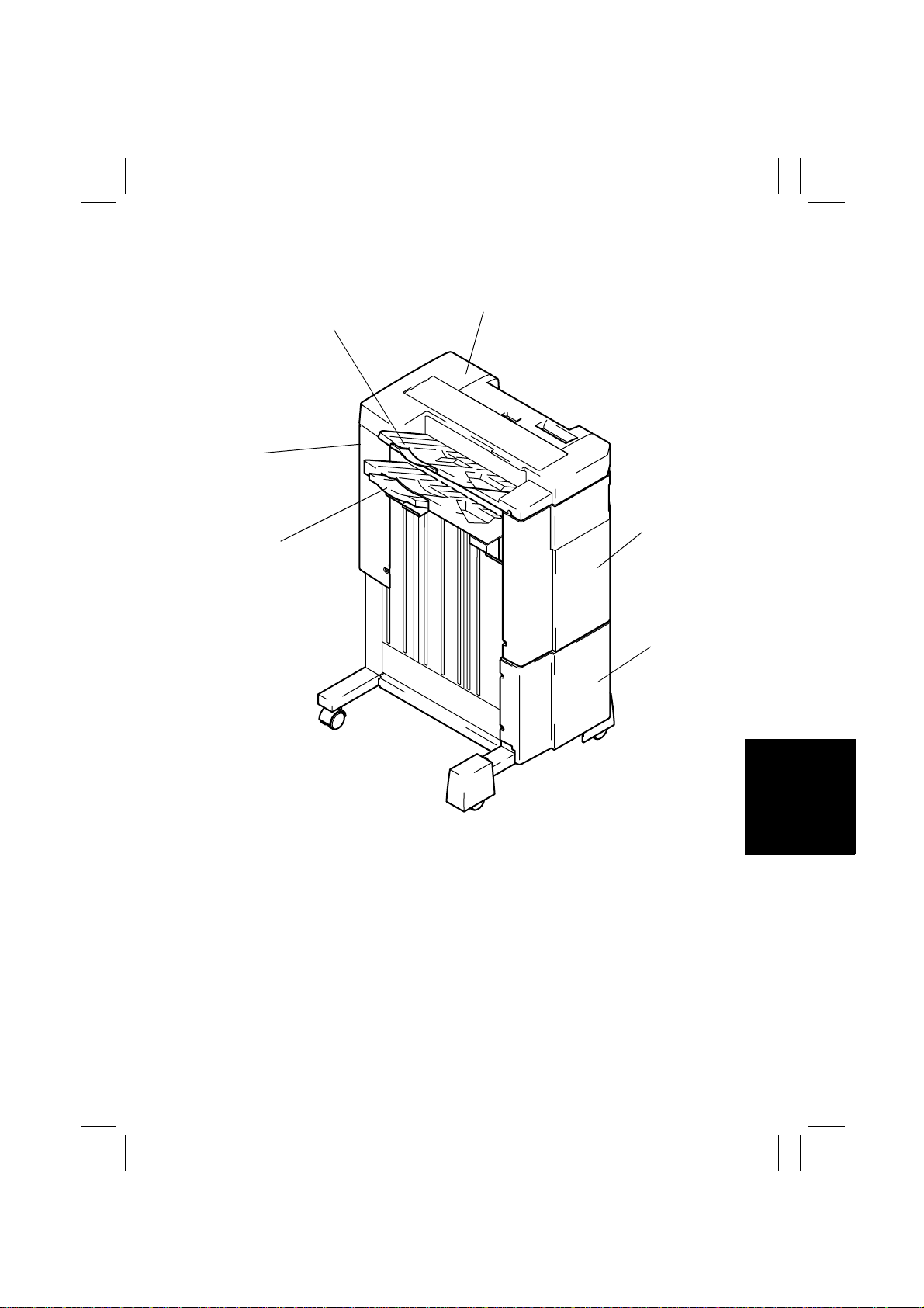
2. PARTS IDENTIFICATION
2
1
6
5
1. 1st Tray
2. Upper Cover
3. Upper Front Cover
3
4
4643M001AA
4. Lower Front Cover
5. Elevator Tray
6. Rear Cover
M-3

FrameMaker Ver.5.5(PC) FS-133/FS-134 OPTION FOR 7915/7920
01.02.09
3. CROSS-SECTIONAL VIEW
13
13
2
14
12
11
10
4
9
5
8
6
7
1. 1st Tray Exit Roll
st
2. 1
Tray Exit Roller
3. Upper Path Transport Roller
4. Upper Path Transport Roll
5. Entrance Roller
6. Transport Rolls
7. Transport Rollers
4853M001AB
8. Entrance Roll
9. Lower Path Transport Roll
10. Lower Path Transport Roller
11. Storage Roller
12. Storage Roll
13. Exit Roller
14. Exit Roll
M-4
FrameMaker Ver.5.5(PC) FS-133/FS-134 OPTION FOR 7915/7920
01.02.09
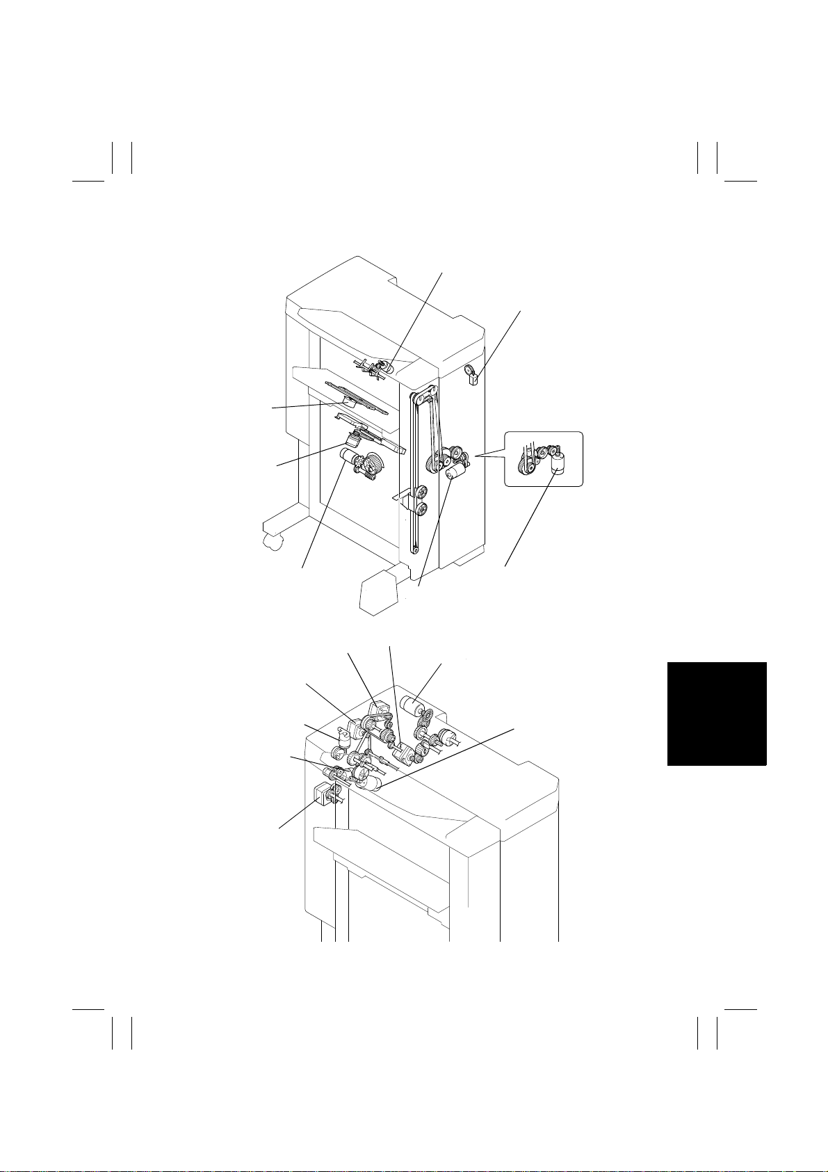
4. DRIVE SYSTEM
Lower Paddle Motor (M9)
Hole Position Selector Motor (M14):
FS-134 (U.S.A. and Canada)
CD Aligning
Motor (M5)
Stapling Unit
Moving Motor (M6)
Shift Motor (M8)
Upper Entrance Motor (M4)
Lower Entrance Motor (M2)
Exit Roller/Rolls
Spacing Motor (M13)
Upper Paddle
Motor (M15)
Exit Motor (M3)
Elevator Motor (M7): FS-133
Elevator Motor (M7): FS-134
Entrance Motor (M1)
Punch Motor (M11): FS-134
4643M003AC
Storage Roller/Rolls
Spacing Motor (M12)
4643M004AA
M-5
FrameMaker Ver.5.5(PC) FS-133/FS-134 OPTION FOR 7915/7920
01.02.09
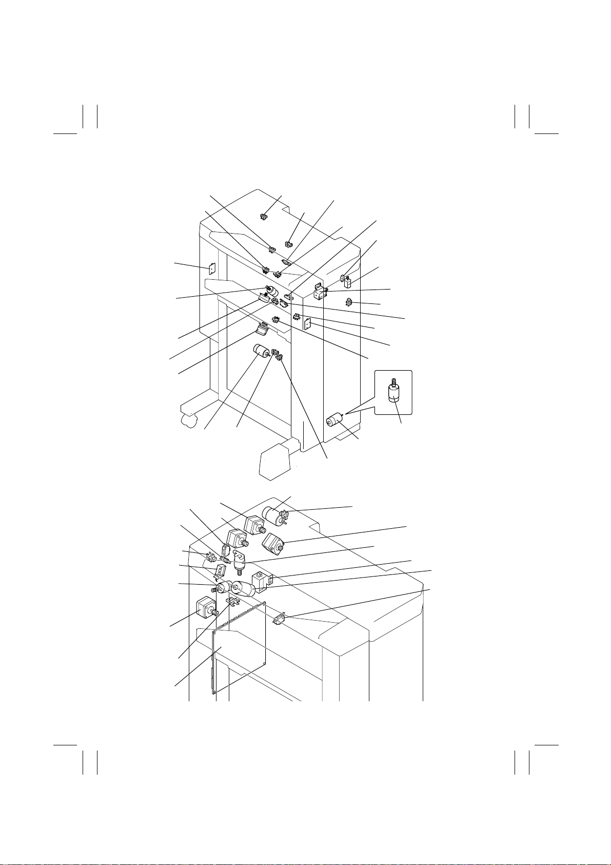
5. ELECTRICAL COMPONENTS LAYOUT
PWB-D
M9
PC8
M5
M6
PC6
PC4
M8
PC11
PC18
PC1
PC2
PC10
PC3
PC5
S4 (✽1): U.S.A. and
Canada
M14 (✽1):U.S.A. and
Canada
SL2
PC17
S2
PC9
PWB-C
PC14
M7 (✽2)
M7 (✽1)
4643M005AC
PC13
SL3
M15
M3
PC12
PWB-A
PC7
S3
M4
M2
M11 (✽1)
PC15 (✽1)
M1
M13
SL1
M12
S1
4643M006AA
M-6

FrameMaker Ver.5.5(PC) FS-133/FS-134 OPTION FOR 7915/7920
01.02.09
Symbol Name Symbol Name
PWB-A Control Board PC1
PWB-C Elevator Tray Upper Limit Sen-
PWB-D Elevator Tray Upper Limit Sen-
M2 Lower Entrance Motor PC6
M3 Exit Motor PC7 Elevator Tray Full Detecting
M4 Upper Entrance Motor
M5 CD Aligning Motor PC8 Elevator Tray Paper Detecting
M6 Stapling Unit Moving Motor
M7 (✽1, ✽2) Elevator Motor PC9 CD Aligning Home Position
M8 Shift Motor
M9 Lower Paddle Motor PC10 Shift Home Position Sensor
M11 (✽1) Punch Motor PC11 Shift Motor Pulse Sensor
M12 Storage Roller/Rolls Spacing
M13 Exit Roller/Rolls Spacing
M14 (✽1) Hole Position Selector Motor PC14 Staple Home Position Sensor
M15 Upper Paddle Motor PC15 (✽1) Punch Motor Pulse Sensor
SL1 Upper/Lower Entrance Switch-
SL2
SL3 Upper Paddle Solenoid
(✽1): Parts used exclusively for FS-134
(✽2): Parts used exclusively for FS-133
sor LED
sor PQ
Motor
Motor
ing Solenoid
st
Tray Entrance Selecting
1
Solenoid
PC2 Lower Entrance Sensor
PC3 Storage Sensor
PC4 Upper Entrance Sensor
PC5 Finisher Tray Paper Detecting
PC12 Storage Roller Home Position
PC13 Exit Roller Home Position Sen-
PC17 Front Door Detecting Sensor
PC18 Upper Cover Detecting Sensor
S1 Set Switch
S2 Elevator Tray Upper Limit
S3 Elevator Tray Lower Limit
S4 (✽1) Hole Punch Position Switch
st
1
Tray Exit Sensor
SensorM1 Entrance Motor
st
Tray Full Detecting Sensor
1
Sensor
Sensor
Sensor
Sensor
sor
Switch
Switch
M-7
FrameMaker Ver.5.5(PC) FS-133/FS-134 OPTION FOR 7915/7920
01.02.09
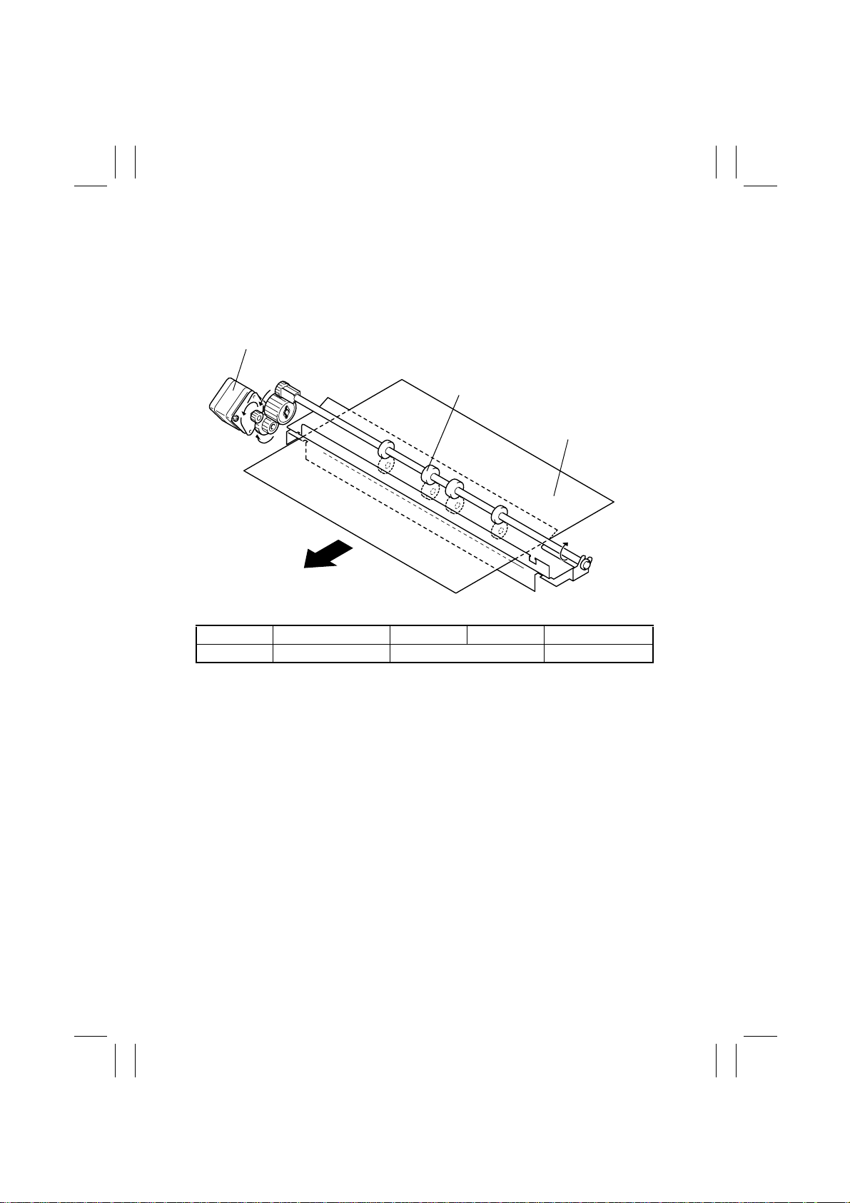
6. PAPER TRANSPORT
6-1. Paper Transport Mechanism
(1) Entrance Section Paper Transport Mechanism
• The Entrance Roller is turned to transport the paper into the Finisher as the Entrance
Motor is energized.
Entrance Motor (M1)
Entrance Roller
Paper
4643M007AD
CONTROL SIGNAL Energized Deenergized WIRING DIAGRAM
M1 PWB-A PJ9A-1~-4 Pulse output 4-B
M-8
FrameMaker Ver.5.5(PC) FS-133/FS-134 OPTION FOR 7915/7920
01.02.09
(2) 1st Tray Paper Transport Mechanism
• Paper transport to the 1
• The Upper Path Transport Roller and 1
st
the 1
Tray as the motor is energized.
st
• The 1
Tray Entrance Selecting Solenoid and Upper/Lower Entrance Switching Solenoid
are energized to select the paper path into the 1
st
Tray takes place when the Finisher is in the Non-Sort mode.
st
Tray Exit Roller turn to transport the paper into
st
Tray.
Upper Entrance Motor (M4)
Upper Path Transport Roller
1st Tray Exit Roller
Paper
SL2
SL1
Upper/Lower Entrance Switching
Solenoid (SL1)
1st Tray Entrance Selecting Solenoid (SL2)
CONTROL SIGNAL Energized Deenergized WIRING DIAG RAM
M4 PWB-A PJ9A-5~-8 Pulse output 4-B
SL1 PWB-A PJ18A-2 H 8-E
SL2 PWB-A PJ18A-4 H 9-E
H
L
H
L
M-9
4643M008AB
4643M011AE
FrameMaker Ver.5.5(PC) FS-133/FS-134 OPTION FOR 7915/7920
01.02.09
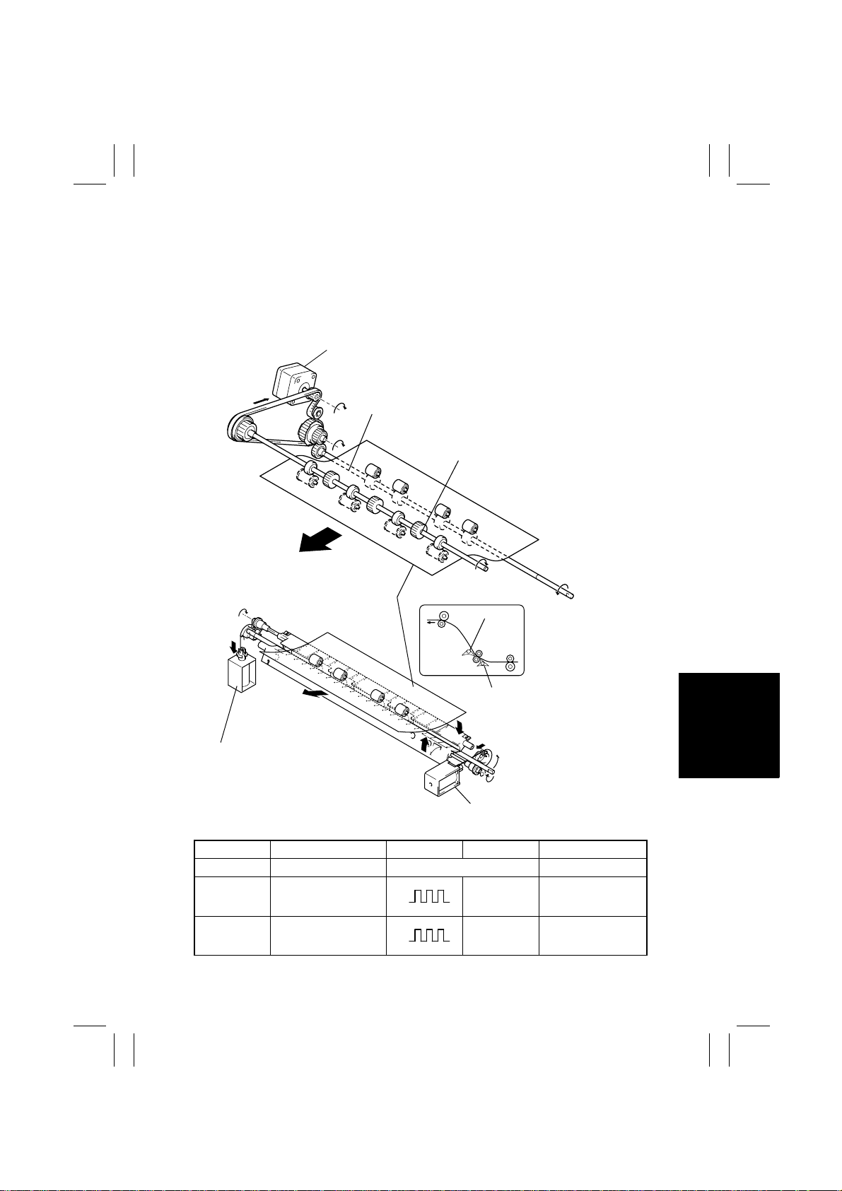
(3) Finisher Tray Paper Transport Mechanism
• Paper transport to the Finisher Tray takes place when the Finisher is in the Staple mode.
• As the Lower Entrance Motor is energized, the Storage Roller turns to transport the
paper toward the exit direction.
• By turning the Exit Motor backward, paper is transported onto the Finisher Tray.
• Either the upper paper path or lower paper path is used to transport paper onto the
Finisher Tray.
• The upper paper path is selected when the Upper/Lower Entrance Switching Solenoid is
st
energized, while the 1
Tray Entrance Selecting Solenoid is deenergized.
• The lower paper path is selected when the Upper/Lower Entrance Switching Solenoid is
deenergized.
Lower Entrance Motor (M2)
Finisher Tray
Storage Roller
Lower Path Transport Roller
Paper
Exit Motor (M3)
1st Tray Entrance Selecting Solenoid (SL2)
4643M009AG
Upper/Lower Entrance Switching Solenoid (SL1)
CONTROL SIGNAL Energized Deenergized WIRING DIAGRAM
M2 PWB-A PJ9A-9~-12 Pulse output 4-A
M-10

FrameMaker Ver.5.5(PC) FS-133/FS-134 OPTION FOR 7915/7920
01.02.09
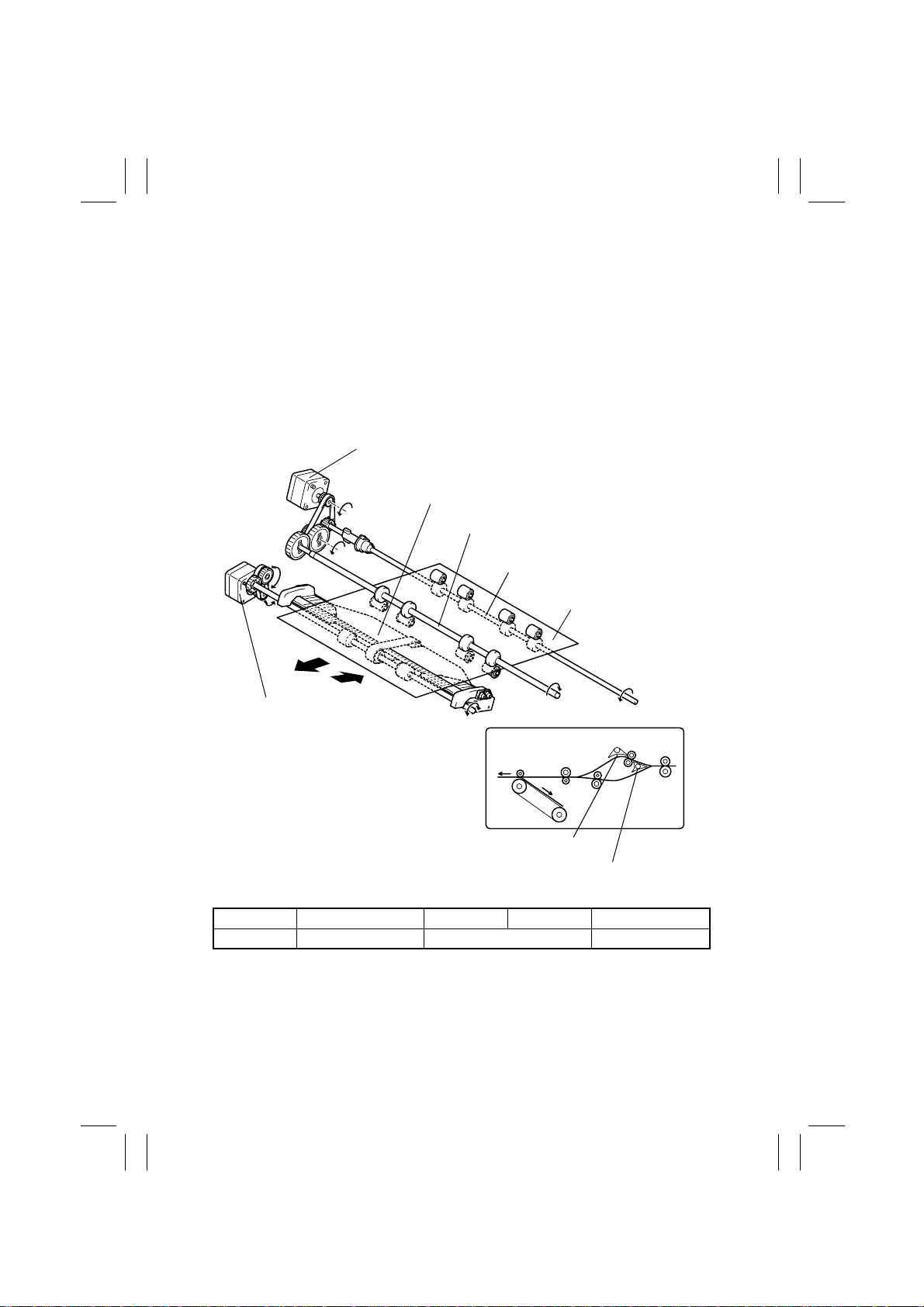
(4) Elevator Tray Paper Transport Mechanism
• Paper transport to the Elevator Tray takes place when the Finisher is in the Sort or Group
mode.
• As the motor is energized, the Exit Roller turns to transport the paper into the Elevator
Tray.
• Either the upper paper path or lower paper path is used to transport paper onto the
Elevator Tray.
• The upper paper path is selected when the Upper/Lower Entrance Switching Solenoid is
st
energized, while the 1
Tray Entrance Selecting Solenoid is deenergized.
• The lower paper path is selected when the Upper/Lower Entrance Switching Solenoid is
deenergized.
Exit Motor (M3)
Finisher Tray
Exit Roller
Paper
Elevator Tray
4643M010AF
1st Tray Entrance Selecting Solenoid (SL2)
Upper/Lower Entrance Switching Solenoid (SL1)
4643M012AD
CONTROL SIGNAL Energized Deenergized WIRING DIAGRAM
M3 PWB-A PJ8A-1~-4 Pulse output 3-A
M-11
FrameMaker Ver.5.5(PC) FS-133/FS-134 OPTION FOR 7915/7920
01.02.09
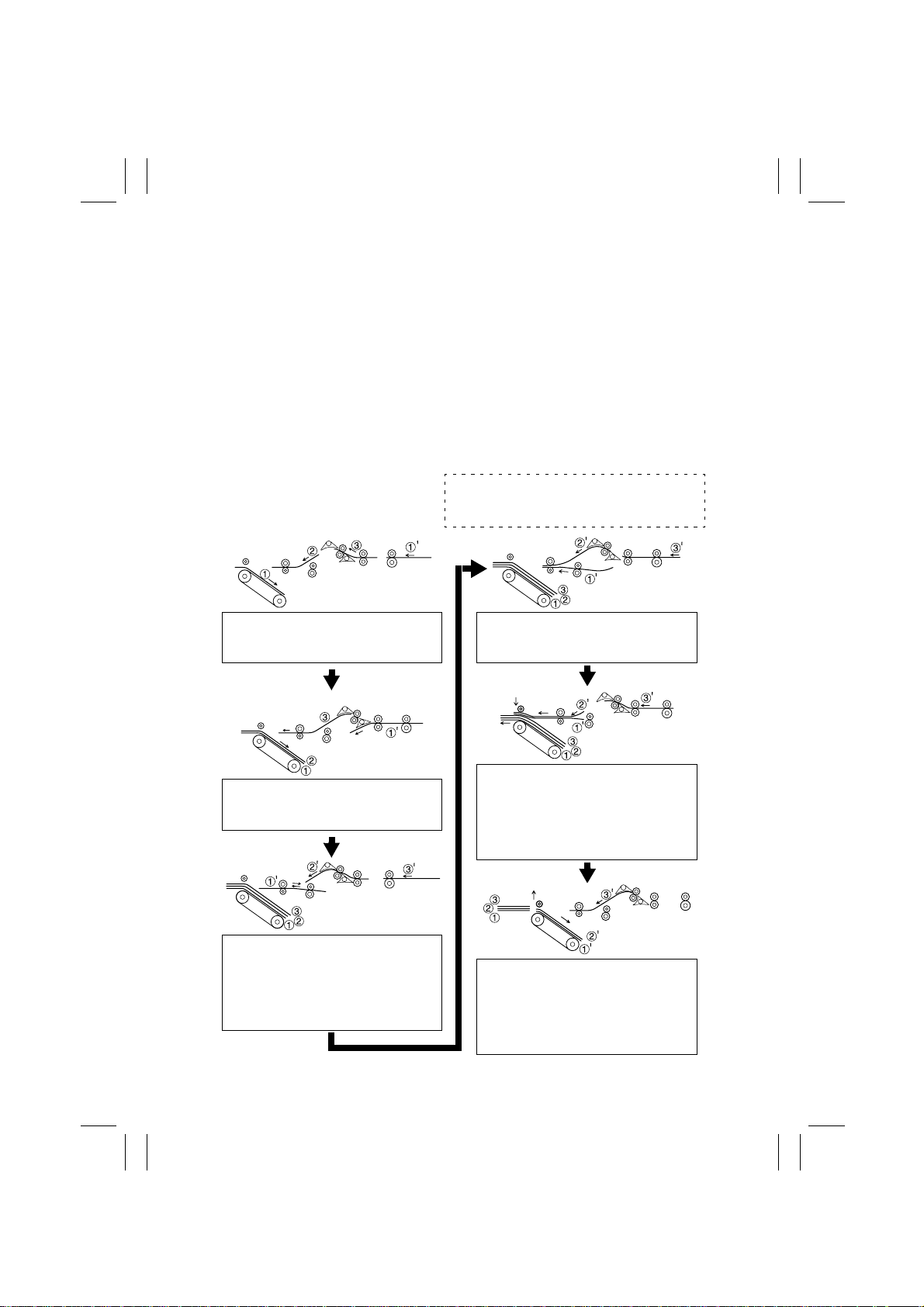
6-2. Paper Switchback Mechanism
• When the last paper of the first copy set is transported onto the Finisher Tray during a
multi-copy cycle in the Sort Staple mode, the first paper of the subsequent copy set,
which is to be next transported, undergoes a switchback sequence. The paper for the
switchback is transported via the lower paper path.
• The second paper of the second copy set is placed over the paper which has undergone
the switchback sequence. After the first copy set has been fed into the Elevator Tray, the
first and second sheets of paper of the second copy set are together transported onto the
Finisher Tray.
• The switchback sequence of the paper is performed by turning the motor backward,
which turns the Lower Path Transport Roller and Storage Roller backward.
• The sheet of paper to be transported next to the one subjected to the switchback
sequence is transported via the upper paper path.
• No switchback sequence is carried out if the interval between sheets of paper is wide as
when using paper of a large size.
<Three A4C originals for two copy sets>
➀, ➁, ➂
➀
: Sheets of paper for the first copy set
’, ➁’, ➂’: Sheets of paper for the second
copy set
4643M027AD
The sheets of paper for the first copy
are transported via the upper paper
path onto the Finisher Tray.
4643M031AH
The first sheet of paper of the second
copy set is transported via the lower
paper path.
4643M028AG
The first sheet of paper of the second
copy set undergoes the switchback
sequence and stops. The second
sheet of paper stops as soon as its
trailing edge leaves the Entrance
Roller.
4643M029AG
The first and second sheets of paper
of the second copy set are transported
together, one on top of the other.
4643M030AH
The Exit Rolls are pressed against the
Exit Roller to feed the sheets of paper
of the first copy set out. At the same
time, the first and second sheets of
paper of the second copy set are
transported toward the exit.
4643M032AE
When the first copy set is fed out, the
Exit Roller starts turning backward to
transport the first and second sheets
of paper of the second copy set to the
Finisher Tray. The Exit Rolls leave the
Exit Roller.
M-12
FrameMaker Ver.5.5(PC) FS-133/FS-134 OPTION FOR 7915/7920
01.02.09
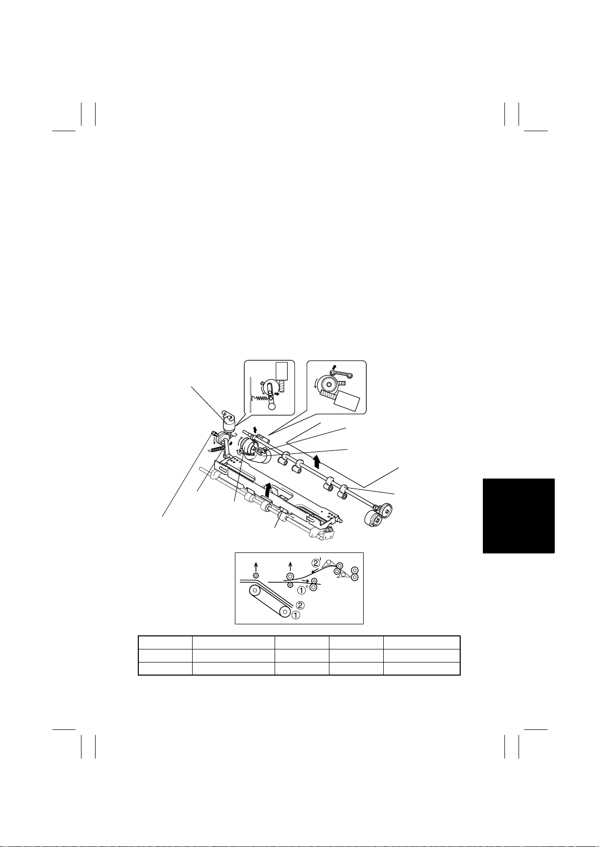
6-3. Roller/Rolls Spacing Mechanism
(1) Storage Roller/Rolls Spacing Mechanism
• The Storage Roller briefly stops when the first sheet of paper completes a switchback
sequence during a multi-copy cycle in the Sort Staple mode. If, however, paper measures 217 mm or more in the FD direction, the leading edge of the second sheet of paper
reaches the Storage Roller before the roller stops turning. The Storage Roller is therefore
raised up to allow a given clearance from the Storage Rolls.
• The Storage Roller is spaced from the Storage Rolls as a cam is turned by the corresponding motor.
(2) Exit Roller/Rolls Spacing Mechanism
• Paper needs to be temporarily transported to the Finisher Tray in the Staple mode, which
makes it necessary to raise the Exit Rolls to provide a given clearance from the Exit
Roller.
• After the stapling sequence has been completed, the Exit Rolls are lowered and pressed
against the Exit Roller so that the paper can be fed out.
• The Exit Rolls are spaced from the Exit Roller as a lever is moved to the right and left by
the cam which is rotated by the motor.
Exit Roller/Rolls
Spacing Motor (M13)
Storage Roller Home Position
Sensor (PC12)
Storage Roller/Rolls Spacing
Motor (M12)
Lever
Cam
Exit Rolls Home Position
Sensor (PC13)
Exit Rolls
4643M033AD
CONTROL SIGNAL Energized Deenergized WIRING DIAGRAM
M12 PWB-A PJ8A-6 Pulse output L 3-A
M13 PWB-A PJ16A-2 H L 9-D
M-13
Storage Roller
4643M013AE
 Loading...