

Konica 7920 Wiring Diagram st134e

FrameMaker Ver.5.5(PC) ST-134 OPTION FOR 7915/7920
01.02.09
ST-134
SERVICE MANUAL
11563

FrameMaker Ver.5.5(PC) ST-134 OPTION FOR 7915/7920
01.02.09
CONTENTS
GENERAL,
MECHANICAL/ELECTRICAL
1. SPECIFICATIONS ........................................................................................... M-1
2. COMPONENTS IDENTIFICATION .................................................................M-2
3. CROSS-SECTIONAL VIEW ............................................................................M-3
4. DRIVE SYSTEM ..............................................................................................M-4
5. ELECTRICAL COMPONENTS LAYOUT ........................................................M-5
6. PAPER TRANSPORT .....................................................................................M-6
6-1. Paper Transport Mechanism ...................................................................M-7
(1) Entrance Section Paper Transport Mechanism ...............................M-7
(2) Non-Sort Bin Paper Transport Mechanism . .....................................M-8
(3) 2nd to 10th Bin Paper Transport Mechanism ..................................M-9
6-2. Paper Exit Detection ................................................................................M-12
6-3. Paper Empty Detection . ...........................................................................M-12
6-4. Paper Full Detection . ...............................................................................M-13
7. Horizontal Unit .................................................................................................M-14
7-1. Paper Transport Mechanism ...................................................................M-14
(1) Paper Path Switching Mechanism ...................................................M-14
(2) Sorter Paper Transport Mechanism ................................................M-15
TEST MODES
1. OUTLINE OF THE TEST MODES ...................................................................S-1
1-1. Test Mode Setting Procedure ..................................................................S-1
(1) Starting of Test Mode ......................................................................S-1
(2) Running Different Test Mode Operations ........................................S-1
(3) Exiting Test Mode ............................................................................S-1
1-2. Description of Each Test Mode Operation ...............................................S-2
(1) Initial Display ................................................................................... S-2
(2) Sensor Input Check .........................................................................S-3
(3) Transport Speed Setting ..................................................................S-4
(4) Initial Operation ...............................................................................S-4
(5) Paper Size Input: Not used ..............................................................S-4
(6) Sorting Check ........................... ........................... ............................S-4
(7) Solenoid Check ...............................................................................S-5
(8) Paper Entrance Switching Check ....................................................S-5
DIS/REASSEMBLY, ADJUSTMENT
1. DIS/REASSEMBLY .........................................................................................D-1
1-1. Maintenance Schedule ............................................................................D-1
1-2. Removal of the External Covers ..............................................................D-1
2. ADJUSTMENT .................................................................................................D-2
2-1. Adjusting the Solenoid ................................................... ..........................D-2
(1) Adjusting the Non-So rt Bin Solenoid .................................... ...........D-2
(2) Entrance Switching Solenoid Adjustment ........................................D-2
2-2. Adjustment of Tension of Timing Belts .................... ........................... .....D-3
(1) Transport Motor Ti ming Be lts ........................................ ............... ...D-3
i

FrameMaker Ver.5.5(PC) ST-134 OPTION FOR 7915/7920
01.02.09
(2) Drive Mechanism Timing Belt ..........................................................D-3
2-3. Adjustment of the Ex it Se n sor ................................. ........................... .....D-4
2-4. Adjustment of the Bin Empty Sensors ..................... ................................D-5
TROUBLESHOOTING
1. SENSOR CHECK ............................................. ........................... ....................T-1
1-1. Sensor Check Scre en ......................... ........................... ..........................T-1
2. MISFEED DETECTION AND TROUBLESHOOTING .....................................T-2
2-1. Missfeed Detecting Sensor Layout ..........................................................T-2
2-2. Missfeed Detection ..................................................................................T-3
2-3. Misfeed Troubleshooting Procedures ......................................................T-4
3. MALFUNCTION DETECTION AND TROUBLESHOOTING
PROCEDURES ...............................................................................................T-5
3-1. Malfunction Detection ..............................................................................T-5
3-2. Malfunction Troubleshooting Procedures ................................................ T-5
4. Time chart .................................... ............... ........................... ..........................T-6
4-1. Paper Path Switching/Non-sort Mode ......................................................T-6
4-2. Sort Mode ................................................................................................T-7
ii

FrameMaker Ver.5.5(PC) ST-134 OPTION FOR 7915/7920
01.02.09
GENERAL,
MECHANICAL/ELECTRICAL
FrameMaker Ver.5.5(PC) ST-134 OPTION FOR 7915/7920
01.02.09
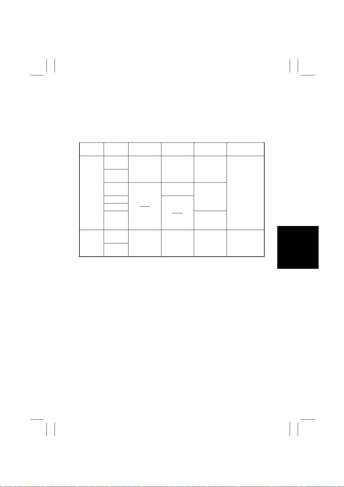
1. SPECIFICATIONS
Type : 10-Bin Mailbin Sorter
Installation : Freestanding
Modes : Non-Sort
Mail Sort
Copy Medium
Mode
Non-Sort
Mail Sort
*: (Recommend paper)
Paper
Type
Plain
paper
Recycled
paper
Thick
paper
Postcards
Envelopes
OHP
Transpar-
encies
Plain
paper
Recycled
paper
Paper Size Paper Weight Capacity Exit Bin
A3L to A6L
11 × 17 to
5-1/2 × 8-1/2
A3L to A5L
11 × 17 to
5-1/2 × 8-1/2
60 to 90 g/m
16 to 24 lb
91 to 209 g/m
60 to 90 g/m
16 to 24 lb
2
200 sheets*
2
20 sheets
2
200 sheets*
32 mm
1 sheet
32 mm
Non-Sort Bin
Non-Sort Bin to
th
Bin
10
Registration : Center
Power Requirements : DC24 V (supplied from copier)
Power Consumption : 32 W
Dimensions : Width: 554 mm
Mass : 10-Bin Mailbin Sorter: 29 kg
Environmental Requirements
DC5 V (generated by sorter)
Depth: 512 mm
Height: 874 mm
Horizontal Transport Unit: 2.6 kg
: Same as copier
M-1
FrameMaker Ver.5.5(PC) ST-134 OPTION FOR 7915/7920
01.02.09
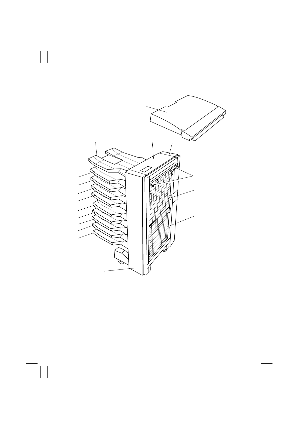
2. COMPONENTS IDENTIFICATION
Horizontal Transport Unit
17
10-Bin Mailbin Sorter
1
2
3
4651M507AA
16
15
14
13
12
11
10
9
8
7
1. Non-Sort Bin
2. Upper Cover
3. Rear Cover
4. Horizontal Unit Mounting Bracket
5. Upper Door
6. Lower Door
7. Front Cover
th
Bin
8. 10
th
9. 9
Bin
4651M501AA
th
10. 8
Bin
th
11. 7
Bin
th
12. 6
Bin
th
13. 5
Bin
th
14. 4
Bin
rd
15. 3
Bin
nd
16. 2
Bin
17. Horizontal Unit Door
4
5
6
M-2
FrameMaker Ver.5.5(PC) ST-134 OPTION FOR 7915/7920
01.02.09
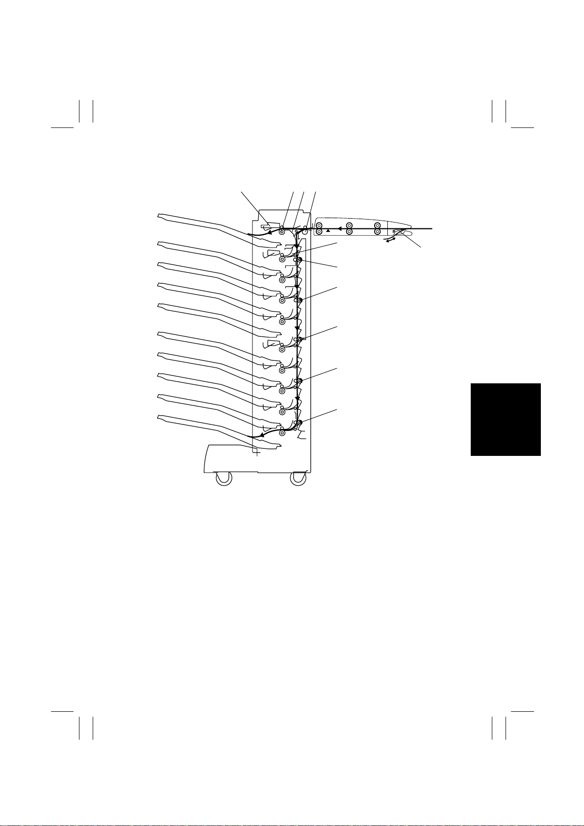
3. CROSS-SECTIONAL VIEW
3
1
2 4
Horizontal Unit10-Bin Mailbin Sorter
5
11
6
7
8
9
1. Sensor Board: Non-Sort Bin to 10th Bin
2. Exit Roller: Non-Sort Bin to 10
3. Switching Deflector A: Non-Sort Bin
4. Entrance Roller
5. Switching Deflector B: 2
th
Bin
nd
Bin to 10th Bin
10
4651M502AA
6. Transport Roller 1
7. Transport Roller 2
8. Transport Roller 3
9. Transport Roller 4
10. Transport Roller 5
11. Entrance Switching Deflector
M-3
FrameMaker Ver.5.5(PC) ST-134 OPTION FOR 7915/7920
01.02.09
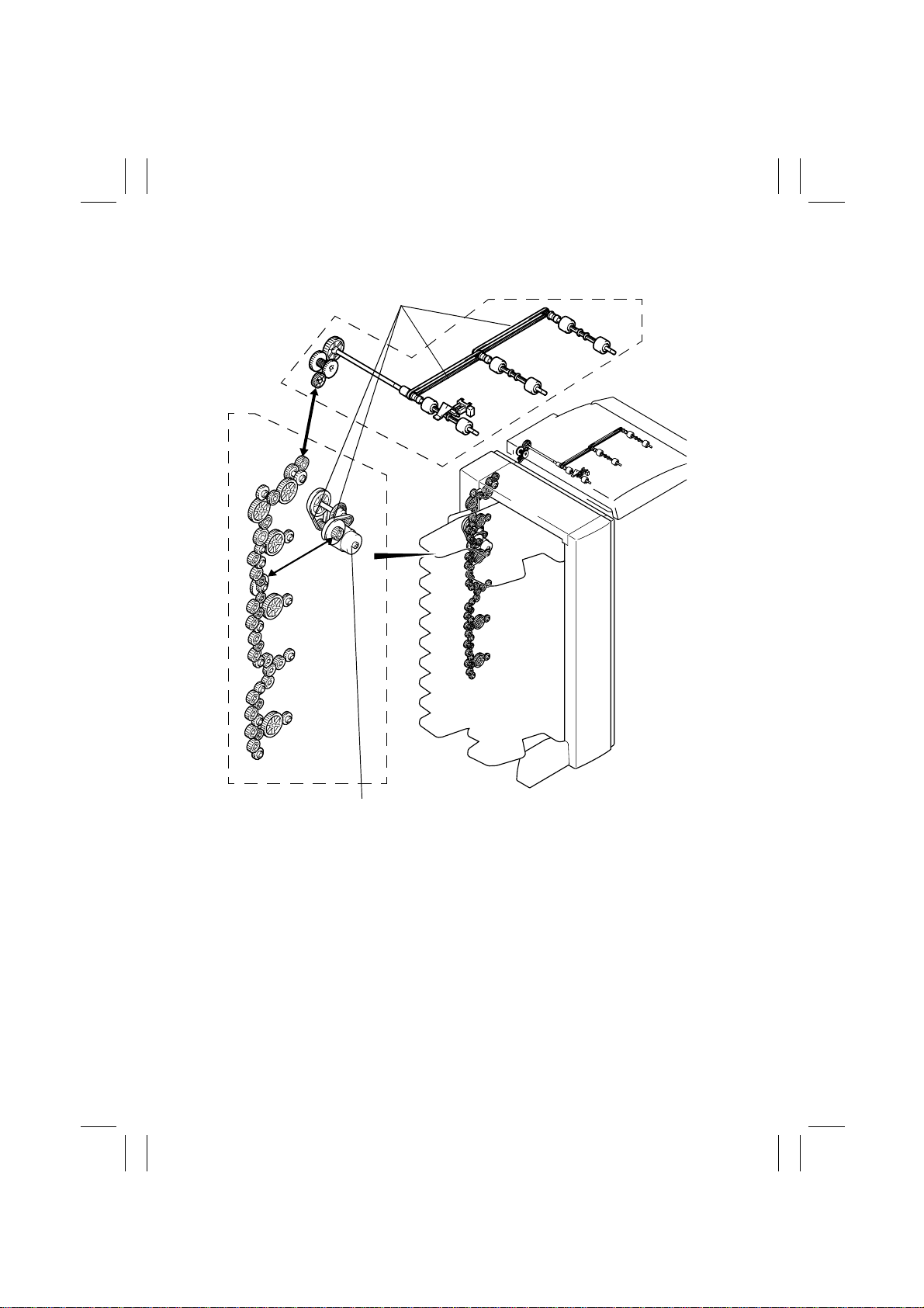
4. DRIVE SYSTEM
Timing Belt
Horizontal
Unit
Transport Motor M1
10-Bin Mailbin Sorter
4651M503AA
M-4

FrameMaker Ver.5.5(PC) ST-134 OPTION FOR 7915/7920
01.02.09
5. ELECTRICAL COMPONENTS LAYOUT
PC6
PC4
SL1
PC1
M1
S1
PWB-A
PWB-B
PWB-D1
PWB-D2
PWB-D3
PWB-D4
PWB-D5
PWB-D6
PWB-D7
PWB-D8
PWB-D9
PWB-C
SL1
Horizontal Unit
(Assy)
SL2
(Assy)
SL3
10-Bin Mailbin Sorter
PC1
4651M504AA
10-Bin Mailbin Sorter
Code Name Code Name
M1 Transport Motor PWB-D1 Non-Sor t Bin Sensor Board
PC1 Transport Motor Pulse Sensor PWB-D2
S1 Set Switch PWB-D3
SL1 Non-Sort Bin Solenoid PWB-D4
SL2 Upper Entrance Switching Solenoid PWB-D5
SL3 Lower Entrance Switching Solenoid PWB-D6
PWB-A Control Board PWB-D7
PWB-B Exit Sensor Board PWB-D8
PWB-C
th
Bin Sensor Board
10
PWB-D9
nd
Bin Sensor Board
2
rd
Bin Sensor Board
3
th
Bin Sensor Board
4
th
Bin Sensor Board
5
th
Bin Sensor Board
6
th
Bin Sensor Board
7
th
Bin Sensor Board
8
9th Bin Sensor Board
Horizontal Unit
Code Name Code Name
SL1 Entrance Switching Solenoid PC4 Horizontal Unit Door Sensor
PC1 Paper Sensor PC6 Turnover Empty Detecting Sensor
M-5
FrameMaker Ver.5.5(PC) ST-134 OPTION FOR 7915/7920
01.02.09
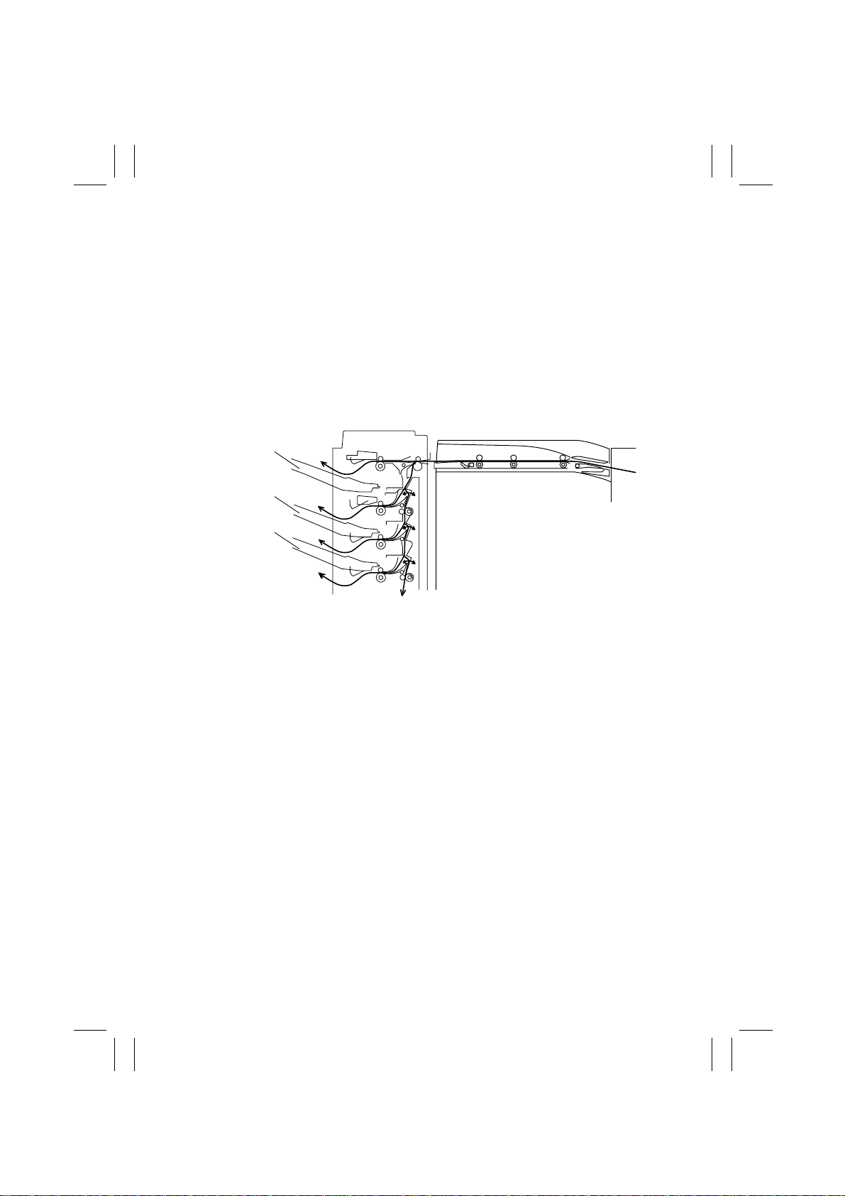
6. PAPER TRANSPORT
• The paper transport mechanism transports copies fed from the copier through the Horizontal Unit into the designated bin.
1. Non-Sort Mode
• All copies are fed into the Non-Sort Bin.
2. Mail Sort Mode
• Copies are sorted into different bins.
The sequence of bins through which copies are fed can be designated in the order from
the Non-Sort to 10th Bin or from the 10th to Non-Sort Bin.
Horizontal Unit10-Bin Mailbin Sorter
Non-Sort Bin
nd
2
Bin
rd
Bin
3
Copier
4651M506AA
M-6
FrameMaker Ver.5.5(PC) ST-134 OPTION FOR 7915/7920
01.02.09
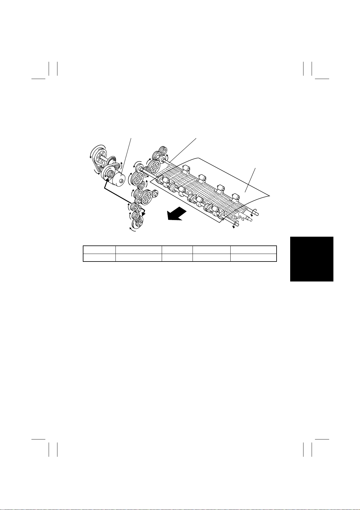
6-1. Paper Transport Mechanism
(1) Entrance Section Paper Transport Mechanism
• Drive from the Transport Motor turns the Entrance Roller so that the copy can be fed into
the Sorter.
Transport Motor M1
CONTROL SIGNAL ENERGIZED DEENERGIZED WIRING DIAGRAM
M1 PWB-A PJ3A-2 L H 2-G
Entrance Roller
Paper
4651M508AA
M-7
FrameMaker Ver.5.5(PC) ST-134 OPTION FOR 7915/7920
01.02.09
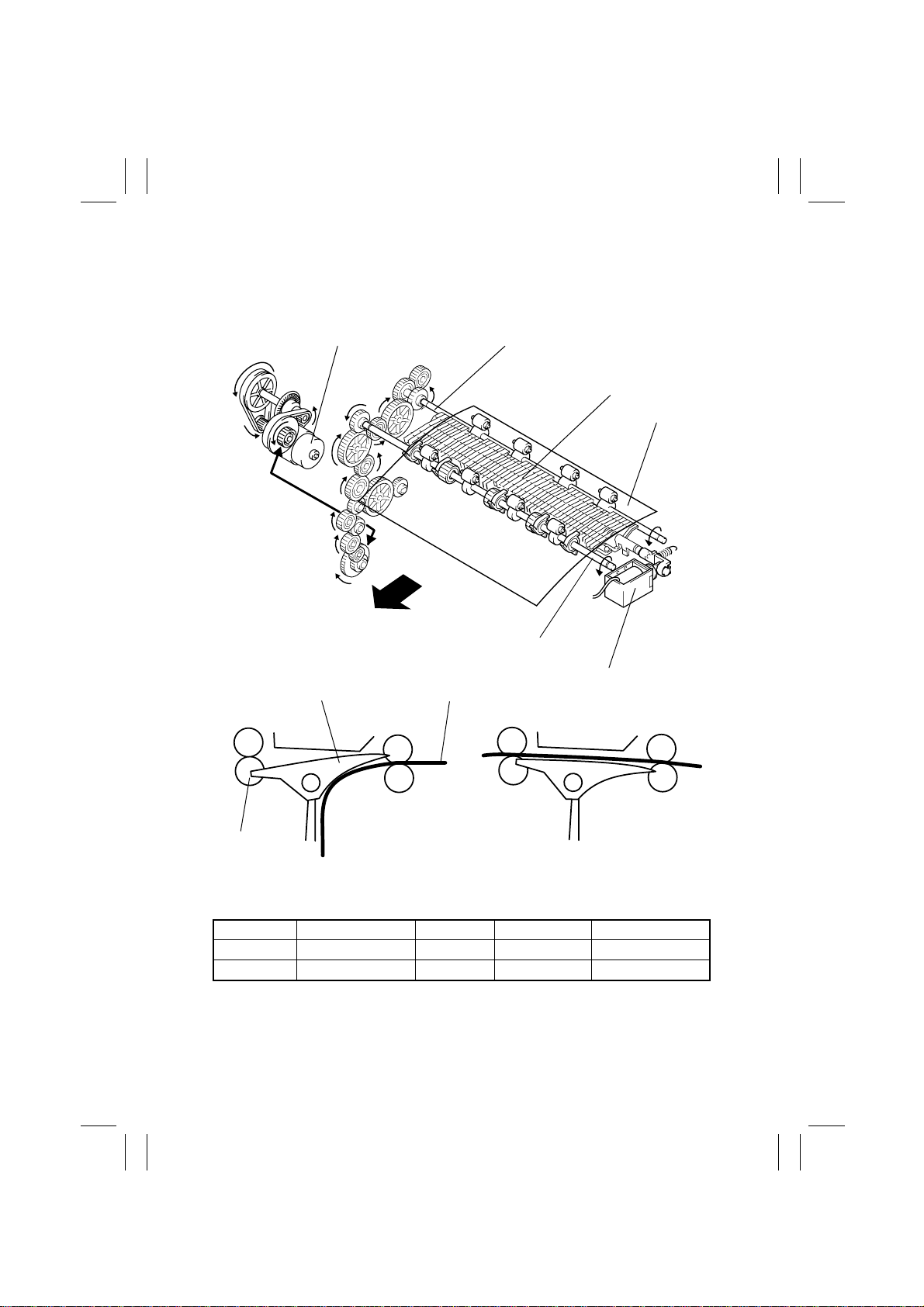
(2) Non-S or t B i n Pa per Transport Mechanism
• In the Non-Sort mode, copies are fed into the Non-Sort Bin.
• Drive from the motor turns the Exit Roller, which feeds the copy into the Non-Sort Bin.
• The path into the Non-Sort Bin is selected when the Non-Sort Bin Solenoid is energized.
Entrance RollerTransport Motor M1
Switching Deflector A
Paper
Exit Roller
Switching Deflector A
Paper
Non-Sort Bin Solenoid
SL1
Exit Roller
Non-Sort Bin Solenoid deenergized
Transport to 2
nd
Bin to 10th Bin
Non-Sort Bin Solenoid energized
Transport to Non-Sort Bin
CONTROL SIGNAL ENERGIZED DEENERGIZED WIRING DIAGRAM
M1 PWB-A PJ3A-2 L H 2-G
SL1 PWB-A PJ4A-2 L H 2-H
4651M509AA
4651M516AA
M-8
 Loading...