

Page 1

7832
SERVICE HANDBOOK
FIELD SERVICE
Dec. 2000
Ver. 1.0
KONICA CORPORATION
TECHNOLOGY SUPPORT CENTER
TOKYO JAPAN
KCS783210
Page 2

INDEX (FIELD SERVICE)
DIS/REASSEMBLY,
ADJUSTMENT
SWITCHES ON PWBs,
TECH. REP. SETTINGS
TROUBLESHOOTING
Page 3

Blank page
Page 4
Safety Precautions for Inspection and Service
When performing inspection and service procedures, observe the following precautions to
prevent accidents and ensure utmost safety.
✽
Depending on the model, some of the precautions given in the following do not apply.
Different markings are used to denote specific meanings as detailed below.
Indicates a potentially hazardous situation which, if not avoided,
WARNING
CAUTION
The following graphic symbols are used to give instructions that need to be observed.
Used to call the service technician’s attention to what is graphically represented
inside the marking (including a warning).
Used to prohibit the service technician’s from doing what is graphically represented inside the marking.
Used to instruct the service technician’s to do what is graphically represented
inside the marking.
1. Always observe precautions.
• Parts requiring special attention in this product will include a label containing the
mark shown on the left plus precautionary notes. Be sure to observe the precautions.
• Be sure to observe the “Safety Information” given in the Operator’s Manual.
could result in death or serious injury.
Indicates a potentially hazardous situation which, if not avoided,
may result in minor or moderate injury. It may also be used to
alert against unsafe practices.
WARNING
2. Before starting the procedures, be sure to unplug the power cord.
• This product contains a high-voltage unit and a circuit with a large current
capacity that may cause an electric shock or burn.
• The product also contains parts that can jerk suddenly and cause injury.
• If this product uses a laser, laser beam leakage may cause eye damage or
blindness.
3. Use the specified parts.
• For replacement parts, always use the genuine parts specified in the manufacturer’s parts manual. Installing a wrong or unauthorized part could cause dielectric breakdown, overload, or undermine safety devices resulting in possible
electric shock or fire.
• Replace a blown electrical fuse or thermal fuse with its corresponding genuine
part specified in the manufacturer’s parts manual. Installing a fuse of a different
make or rating could lead to a possible fire. If a thermal fuse blows frequently,
the temperature control system may have a problem and action must be taken
to eliminate the cause of the problem.
P-1
Page 5
4. Handle the power cord with care and never use a multiple outlet.
• Do not break, crush or otherwise damage the power cord. Placing a heavy
object on the power cord, or pulling or bending it may damage it, resulting in a
possible fire or electric shock.
• Do not use a multiple outlet to which any other appliance or machine is connected.
• Be sure the power outlet meets or exceeds the specified capacity.
5. Be careful with the high-voltage parts.
• A part marked with the symbol shown on the left carries a high voltage. Touching it could result in an electric shock or burn. Be sure to unplug the power cord
before servicing this part or the parts near it.
6. Do not work with wet hands.
• Do not unplug or plug in the power cord, or perform any kind of service or
inspection with wet hands. Doing so could result in an electric shock.
7. Do not touch a high-temperature part.
• A part marked with the symbol shown on the left and other parts such as the
exposure lamp and fusing roller can be very hot while the machine is energized.
Touching them may result in a burn.
• Wait until these parts have cooled down before replacing them or any surrounding parts.
8. Maintain a grounded connection at all times. (This item may not apply in the USA.)
• Be sure to connect the ground wire to the ground terminal even when performing an inspection or repair. Without proper grounding, electrical leakage could
result in an electric shock or fire.
• Never connect the ground wire to a gas pipe, water pipe, telephone ground wire,
or a lightning conductor.
9. Do not remodel the product.
• Modifying this product in a manner not authorized by the manufacturer may
result in a fire or electric shock. If this product uses a laser, laser beam leakage
may cause eye damage or blindness.
10. Restore all parts and harnesses to their original positions.
• To promote safety and prevent product damage, make sure the harnesses are
returned to their original positions and properly secured in their clamps and saddles in order to avoid hot parts, high-voltage parts, sharp edges, or being
crushed.
• To promote safety, make sure that all tubing and other insulating materials are
returned to their original positions. Make sure that floating components mounted
on the circuit boards are at their correct distance and position off the boards.
P-2
Page 6
CAUTION
1. Precautions for Service Jobs
• A toothed washer and spring washer, if used originally, must be reinstalled.
Omitting them may result in contact failure which could cause an electric shock
or fire.
• When reassembling parts, make sure that the correct screws (size, type) are
used in the correct places. Using the wrong screw could lead to stripped
threads, poorly secured parts, poor insulating or grounding, and result in a malfunction, electric shock or injury.
• Take great care to avoid personal injury from possible burrs and sharp edges on
the parts, frames and chassis of the product.
• When moving the product or removing an option, use care not to injure your
back or allow your hands to be caught in mechanisms.
2. Precautions for Servicing with Covers and Parts Removed
• Wherever feasible, keep all parts and covers mounted when energizing the
product.
• If energizing the product with a cover removed is absolutely unavoidable, do not
touch any exposed live parts and use care not to allow your clothing to be
caught in the moving parts. Never leave a product in this condition unattended.
• Never place disassembled parts or a container of liquid on the product. Parts
falling into, or the liquid spilling inside, the mechanism could result in an electric
shock or fire.
• Never use a flammable spray near the product. This could result in a fire.
• Make sure the power cord is unplugged before removing or installing circuit
boards or plugging in or unplugging connectors.
• Always use the interlock switch actuating jig to actuate an interlock switch when
a cover is opened or removed. The use of folded paper or some other object
may damage the interlock switch mechanism, possibly resulting in an electric
shock, injury or blindness.
3. Precautions for the Working Environment
• The product must be placed on a flat, level surface that is stable and secure.
• Never place this product or its parts on an unsteady or tilting workbench when
servicing.
• Provide good ventilation at regular intervals if a service job must be done in a
confined space for a long period of time.
• Avoid dusty locations and places exposed to oil or steam.
• Avoid working positions that may block the ventilation ports of the product.
4. Precautions for Handling Batteries (Lithium, Nickel-Cadmium, etc.)
• Replace a rundown battery with the same type as specified in the manufacturer’s parts manual.
• Before installing a new battery, make sure of the correct polarity of the installation or the battery could burst.
• Dispose of used batteries according to the local regulations. Never dispose of
them at the user’s premises or attempt to try to discharge one.
P-3
Page 7
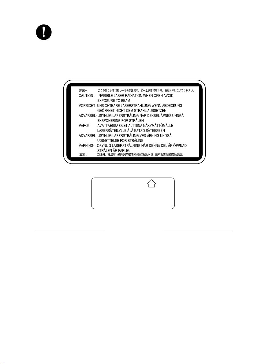
5. Precautions for the Laser Beam (Only for Products Employing a Laser)
• Removing the cover marked with the following caution label could lead to possible exposure to the laser beam, resulting in eye damage or blindness. Be sure
to unplug the power cord before removing this cover.
• If removing this cover while the power is ON is unavoidable, be sure to wear
protective laser goggles that meet specifications.
• Make sure that no one enters the room when the machine is in this condition.
• When handling the laser unit, observe the “Precautions for Handling Laser
Equipment.”
1167P001AA
DANGER
Invisible laser radiation when open.
AVOID DIRECT EXPOSURE
TO BEAM
0947-7127-01
1144D270AA
Other Precautions
• When handling circuit boards, observe the “HANDLING of PWBs”.
• The PC Drum is a very delicate component. Observe the precautions given in “HANDLING OF THE PC DRUM” because mishandling may result in serious image problems.
• Note that replacement of a circuit board may call for readjustments or resetting of particular items, or software installation.
P-4
Page 8

Used Batteries Precautions
ALL Areas
Danger of explosion if battery is incorrectly replaced.
Replace only with the same or equivalent type recommended by the manufacturer.
Dispose of used batteries according to the manufacturer’s instructions.
Germany
Explosionsgefahr bei unsachgemäßem Austausch der Batterie.
Ersatz nur durch denselben oder einen vom Hersteller empfohlenen ähnlichen Typ.
Entsorgung gebrauchter batterien nach Angaben des Herstellers.
France
Ily a danger d’explosion s’ily a remplacement incorrec de la batterie.
Remplacer uniquement avec une batterie du meme type ou d’un type équivalent recommande par le constructueur.
Mettre au rebut les batteries usageés conformément aux instructions du fabricant.
Denmark
Lithiumbatteri - Eksplosionsfare ved fejlagtig håndtering Udskiftning må kun ske med batteri af samme fabrikat og type.
Levér det brugte batteri tilbage til leverandøren.
Norway
Eksplosjonsfare ved feilaktig skifte av batteri.
Benytt samme batteritype eller en tilsvarende type anbefalt av apparatfabrikanten.
Brukte batterier kasseres i henhold til fabrikantens instruksjoner.
CAUTION
VORSICHT!
ATTENTION
ADVARSEL!
ADVARSEL
Sweden
Explosionsfara vid felaktigt batteribyte.
Använd samma batterityp eller en ekvivalent typ som rekommenderas av apparattillverkaren.
Kassera använt batteri enligt fabrikantens instruktion.
Finland
Paristo voi räjähtää, los se on virheellisesti asennettu.
Vaihda paristo ainoastaan laitevalmistajan suosittelemaan tyyppiin. Hävitä Käytetty paristo
valmistajan ohjeiden mukaisesti.
VARNING
VAROlTUS
P-5
Page 9

Precautions for Service
When performing inspection and service procedures, observe the following precautions to
prevent mishandling of the machine and its parts.
✽
Depending on the model, some of the precautions given in the following do not apply.
Precautions Before Service
• When the user is using a word processor or personal computer from a wall outlet of the
same line, take necessary steps to prevent the circuit breaker from opening due to overloads.
• Never disturb the LAN by breaking or making a network connection, altering termination,
installing or removing networking hardware or software, or shutting down networked
devices without the knowledge and express permission of the network administrator or
the shop supervisor.
How to Use this Book
1. DIS/REASSEMBLY, ADJUSTMENT
• To reassemble the product, reverse the order of disassembly unless otherwise specified.
2. TROUBLESHOOTING
• If a component on a PWB or any other functional unit including a motor is defective, the
text only instructs you to replace the whole PWB or functional unit and does not give
troubleshooting procedures applicable within the defective unit.
• All troubleshooting procedures contained herein assume that there are no breaks in the
harnesses and cords and all connectors are plugged into the right positions.
• The procedures preclude possible malfunctions due to noise and other external causes.
Precautions for Service
• Check the area surrounding the service site for any signs of damage, wear or need of
repair.
• Keep all disassembled parts in good order and keep tools under control so that none will
be lost or damaged.
• After completing a service job, perform a safety check. Make sure that all parts, wiring
and screws are returned to their original positions.
• Do not pull out the toner hopper while the toner bottle is turning. This could result in a
damaged motor or locking mechanism.
• If the product is to be run with the front door open, make sure that the toner hopper is in
the locked position.
• Do not use an air gun or vacuum cleaner for cleaning the ATDC Sensor and other sensors, as they can cause electrostatic destruction. Use a blower brush and cloth. If a unit
containing these sensors is to be cleaned, first remove the sensors from the unit.
P-6
Page 10

Precautions for Dis/Reassembly
• Be sure to unplug the copier from the outlet before attempting to service the copier.
• The basic rule is not to operate the copier anytime during disassembly. If it is absolutely
necessary to run the copier with its covers removed, use care not to allow your clothing
to be caught in revolving parts such as the timing belt and gears.
• Before attempting to replace parts and unplug connectors, make sure that the power
cord of the copier has been unplugged from the wall outlet.
• Be sure to use the Interlock Switch Actuating Jig whenever it is necessary to actuate the
Interlock Switch with the covers left open or removed.
• While the product is energized, do not unplug or plug connectors into the circuit boards
or harnesses.
• Never use flammable sprays near the copier.
• A used battery should be disposed of according to the local regulations and never be dis-
carded casually or left unattended at the user’s premises.
• When reassembling parts, make sure that the correct screws (size, type) and toothed
washer are used in the correct places.
• If it becomes necessary to replace the thermal fuse or any other fuse mounted on a
board, be sure to use one of the rating marked on the blown fuse. Always note the rating
marked on the fuse, as the rating and mounting site or number used are subject to
change without notice.
Precautions for Circuit Inspection
• Never create a closed circuit across connector pins except those specified in the text and
on the printed circuit.
• When creating a closed circuit and measuring a voltage across connector pins specified
in the text, be sure to use the GND wire.
P-7
Page 11

Handling of PWBs
1. During Transportation/Storage:
• During transportation or when in storage, new P.W. Boards must not be indiscriminately
removed from their protective conductive bags.
• Do not store or place P.W. Boards in a location exposed to direct sunlight and high temperature.
• When it becomes absolutely necessary to remove a Board from its conductive bag or
case, always place it on its conductive mat in an area as free as possible from static electricity.
• Do not touch the pins of the ICs with your bare hands.
• Protect the PWBs from any external force so that they are not bent or damaged.
2. During Inspection/Replacement:
• Avoid checking the IC directly with a multimeter; use connectors on the Board.
• Never create a closed circuit across IC pins with a metal tool.
• Before unplugging connectors from the P.W. Boards, make sure that the power cord has
been unplugged from the outlet.
• When removing a Board from its conductive bag or conductive case, do not touch the
pins of the ICs or the printed pattern. Place it in position by holding only the edges of the
Board.
• When touching the PWB, wear a wrist strap and connect its cord to a securely grounded
place whenever possible. If you cannot wear a wrist strap, touch a metal part to discharge static electricity before touching the PWB.
• Note that replacement of a PWB may call for readjustments or resetting of particular
items.
Handling of Other Parts
• The magnet roller generates a strong magnetic field. Do not bring it near a watch, floppy
disk, magnetic card, or CRT tube.
P-8
Page 12
Handling of the PC Drum
✽
Only for Products Not Employing an Imaging Cartridge.
1. During Transportation/Storage:
• Use the specified carton whenever moving or storing the PC Drum.
• The storage temperature is in the range between –20°C and +40°C.
• In summer, avoid leaving the PC Drum in a car for a long time.
2. Handling:
• Ensure that the correct PC Drum is used.
• Whenever the PC Drum has been removed from the copier, store it in its carton or pro-
tect it with a Drum Cloth.
• The PC Drum exhibits greatest light fatigue after being exposed to strong light over an
extended period of time. Never, therefore, expose it to direct sunlight.
• Use care not to contaminate the surface of the PC Drum with oil-base solvent, fingerprints, and other foreign matter.
• Do not scratch the surface of the PC Drum.
• Do not apply chemicals to the surface of the PC Drum.
• Do not attempt to wipe clean the surface of the PC Drum.
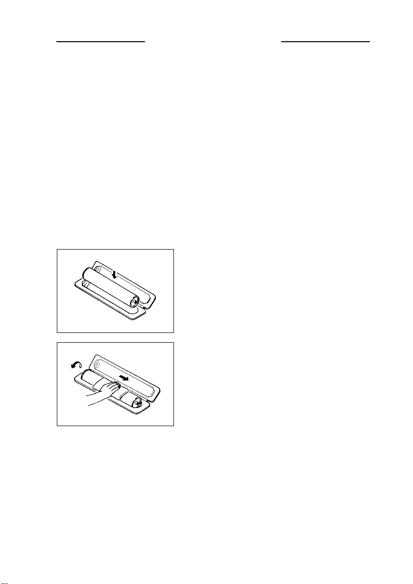
If, however, the surface is contaminated with fingerprints, clean it using the following procedure.
1. Place the PC Drum into one half of its carton.
1076D001
1076D002
2. Gently wipe the residual toner off the surface of the
PC Drum with a dry, Dust-Free Cotton Pad.
A. Turn the PC Drum so that the area of its surface on
which the line of toner left by the Cleaning Blade is
present is facing straight up. Wipe the surface in
one continuous movement from the rear edge of
the PC Drum to the front edge and off the surface
of the PC Drum.
B. Turn the PC Drum slightly and wipe the newly
exposed surface area with a CLEAN face of the
Dust-Free Cotton Pad. Repeat this procedure until
the entire surface of the PC Drum has been thoroughly cleaned.
✽
At this time, always use a CLEAN face of the dry
Dust-Free Cotton Pad until no toner is evident on the
face of the Pad after wiping.
P-9
Page 13
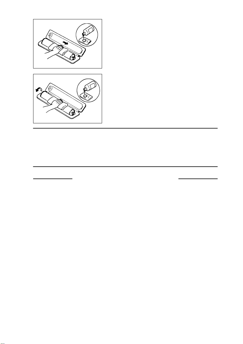
3. Soak a small amount of either ethyl alcohol or isopropyl alcohol into a clean, unused Dust-Free Cotton Pad which has been folded over into quarters.
Now, wipe the surface of the PC Drum in one continuous movement from its rear edge to its front
edge and off its surface one to two times.
✽
Never move the Pad back and forth.
1076D003
4. Using the SAME face of the Pad, repeat the procedure explained in the latter half of step 3 until the
entire surface of the PC Drum has been wiped.
Always OVERLAP the areas when wiping. Two
complete turns of the PC Drum would be appropriate for cleaning.
1076D004
NOTES
• Even when the PC Drum is only locally dirtied, wipe the entire surface.
• Do not expose the PC Drum to direct sunlight. Clean it as quickly as possible even under
interior illumination.
• If dirt remains after cleaning, repeat the entire procedure from the beginning one more
time.
Handling of the Imaging Cartridge
✽
Only for Products Employing an Imaging Cartridge.
1. During Transportation/Storage:
• The storage temperature is in the range between –20°C and +40°C.
• In summer, avoid leaving the Imaging Cartridge in a car for a long time.
2. Handling:
• Store the Imaging Cartridge in a place that is not exposed to direct sunlight.
3. Precautionary Information on the PC Drum Inside the Imaging Cartridge:
• Use care not to contaminate the surface of the PC Drum with oil-base solvent, fingerprints, and other foreign matter.
• Do not scratch the surface of the PC Drum.
• Do not attempt to wipe clean the surface of the PC Drum.
P-10
Page 14

DIS/REASSEMBLY,
ADJUSTMENT
10230
Page 15

Blank page
Page 16

CONTENTS
1. SERVICE INSTRUCTIONS .............................................................................D-1
1-1. IDENTIFICATION OF FUSES AND CIRCUIT BREAKERS ....................D-1
1-2. PRECAUTIONS FOR HANDLING THE LASER EQUIPMENT ...............D-1
1-3. PARTS WHICH MUST NOT BE TOUCHED ...........................................D-2
(1) Red Painted Screws ........................................................................D-2
(2) Variable Resistors on Board ............................................................D-2
(3) Other Screws ...................................................................................D-2
2. DISASSEMBLY AND REASSEMBLY .............................................................D-3
2-1. IDENTIFICATION AND REMOVAL OF EXTERIOR PARTS ...................D-3
2-2. REMOVAL OF CIRCUIT BOARDS AND OTHER ELECTRICAL
COMPONENTS .......................................................................................D-5
2-3. MAINTENANCE SCHEDULE ..................................................................D-7
2-4. REMOVAL OF UNITS .............................................................................D-10
(1) Removal of the Toner Hopper Unit ..................................................D-10
(2) Removal of the PC Unit ...................................................................D-11
(3) Removal of the Developing Unit ......................................................D-13
(4) Removal of the Fusing Unit and Transfer Unit ................................D-14
(5) Removal of the Multi Bypass Unit ....................................................D-15
(6) Removal of the Paper Take-Up Unit ................................................ D-16
(7) Removal of the Paper Exit Unit .......................................................D-17
(8) Removal of the IR Board Assy ........................................................D-18
(9) Removal of the PH Assy .................................................................. D-19
(10) Removal of the PHC Power Supply Board ...................................... D-20
2-5. PAPER TAKE-UP SECTION ................................................................... D-21
(1) Cleaning and Replacement of the Paper Take-Up Roll, Feed Roll,
Separator Roll, and Paper Dust Remover .......................................D-21
(2) Removal of the Synchronizing/Static Charge Roller Assy ............... D-23
(3) Disassembly of the Synchronizing Roller Assy ...............................D-24
(4) Removal of the Drawer Lift-Up Motor Assy ..................................... D-26
(5) Disassembly of the Multi Bypass Unit .............................................D-26
2-6. FUSING/EXIT SECTION .........................................................................D-30
(1) Replacement of the Upper and Lower Fusing Roller Bushings and
Upper and Lower Fusing Rollers .....................................................D-30
(2) Replacement of the Oil Application Roller, Oil Supply Roller, Roller
Drive Gear, and Oil Regulating Blade .............................................D-34
(3) Adding Fuser Oil ..............................................................................D-37
(4) Replacement of the Cleaning Roller ................................................D-38
(5) Replacement of the Oil Collecting Blade and Oil Filter ....................D-39
(6) Cleaning of the Fusing Entrance Guide, Upper and Lower Fusing
Roller Thermistors, and Upper and Lower Fusing Roller
Thermostats ..................................................................................... D-40
(7) Disassembly of the Oil Pump Assy .................................................. D-41
(8) Replacement of the Exit Roller ........................................................D-44
2-7. DEVELOPING UNIT ................................................................................ D-45
(1) Replacement of the ATDC Sensor Window ....................................D-45
i
Page 17

(2) Cleaning of the Ds Rolls, Toner Scattering Prevention Seal 1, and
Toner Scattering Prevention Plate ................................................... D-45
(3) Replacement of the Toner Collecting Box, Air Filter, and Ozone
Filter .............................................................................................D-45
(4) Removal of the Bk Developing Unit .................................................D-46
(5) Removal of the Y, M, and C Developing Units ................................D-47
(6) Disassembly of the Developing Unit ................................................D-48
(7) Cleaning along the Left Edge of the Developing Units .................... D-55
2-8. TONER HOPPER ....................................................................................D-56
(1) Cleaning of the Shutters ..................................................................D-56
(2) Disassembly of the Toner Hopper Unit ............................................ D-57
2-9. PARTS AROUND THE PC UNIT .............................................................D-64
(1) Removal of the PC Drum Charge Corona Assy and Pre-Cleaning
Charge Corona Assy .......................................................................D-64
(2) Cleaning and Replacement of the Pre-Cleaning Charge Corona .... D-64
(3) Cleaning and Replacement of the PC Drum Charge Corona Assy . D-65
(4) Replacement of the Ozone Filter (PC Drum Charge Corona) and
Cleaning of the Main Erase Lamp ...................................................D-66
(5) Disassembly of the PC Unit .............................................................D-67
(6) Cleaning of Toner Scattering Prevention Seal 2 and the Surface
Potential Detection Sensor .............................................................. D-68
(7) Removal of the PC Shaft Ground Plate ...........................................D-69
(8) Cleaning and Replacement of the Pre-Image Transfer Corona
Assy .............................................................................................D-70
2-10.OPTICAL SECTION ................................................................................D-71
(1) Cleaning of the Original Glass ......................................................... D-71
(2) Cleaning of the 1st to 3rd Mirrors, Slide Rails, and Lens Filter ....... D-71
(3) Disassembly of the Optical Section .................................................D-72
(4) Disassembly of the Scanner ............................................................ D-73
(5) Removal of the Scanner Drive Cables ............................................D-74
(6) Winding of Scanner Drive Cables .................................................... D-78
2-11.TRANSFER UNIT ....................................................................................D-79
(1) Replacement of the Ozone Filter .....................................................D-79
(2) Removal of the Paper Separator Corona ........................................D-79
(3) Cleaning of the Paper Separator Finger, Transfer Drum Ring, and
Separating Failure Detecting Sensor ...............................................D-80
(4) Disassembly of the Transfer Unit ....................................................D-80
(5) Cleaning and Replacement of the Paper Separator Corona Assy ..D-82
(6) Replacement of the Scraper Blade, Fur Brush Roller, and Fur Brush
Pressure Spring ...............................................................................D-82
(7) Cleaning of the Fur Brush Roller Assy ............................................D-84
(8) Removal of the Corona Units ..........................................................D-84
(9) Cleaning and Replacement of the Outer Charge Neutralizing
Corona Assy ....................................................................................D-85
(10) Cleaning and Replacement of the Inner Charge Neutralizing
Corona Assy ....................................................................................D-86
(11) Cleaning and Replacement of the Static Charge Corona Assy ....... D-86
ii
Page 18

(12) Cleaning and Replacement of the Image Transfer Corona Assy .... D-87
(13) Replacement of the Transfer Film ................................................... D-88
(14) Installation of the Transfer Film .......................................................D-89
(15) Replacement of Backup Blade 1 and Backup Blade 2 ....................D-92
(16) Replacement of the Static Charge Roller Scraper ...........................D-93
3. ADJUSTMENTS ..............................................................................................D-94
3-1. JIGS AND TOOLS USED ........................................................................D-94
(1) Tools for Setting-up and PM ............................................................D-94
(2) Miscellaneous Jigs ..........................................................................D-95
3-2. ADJUSTMENT REQUIREMENTS FOR CLEANING/REPLACEMENT OF
EACH PART ............................................................................................D-96
3-3. ADJUSTMENT OF SWITCHES ...............................................................D-101
3-4. ADJUSTMENT OF SOLENOIDS .............................................................D-102
(1) Adjustment of the Transfer Drum Retract Solenoid .........................D-102
(2) Adjustment of the Static Charge Roller Solenoid ............................D-103
(3) Adjustment of the Paper Separator Finger Solenoid ....................... D-104
(4) Adjustment of the Internal Fur Brush Solenoid, Backup Brush
Solenoid, and Lifting Finger Solenoid ..............................................D-105
(5) Adjustment of the Manual Feed Paper Pick-Up Solenoid ...............D-106
(6) Adjustment of the Oil Roller Solenoid ..............................................D-107
3-5. ADJUSTMENT OF BELT TENSION ........................................................D-108
3-6. TOUCH PANEL CORRECTION MODE ..................................................D-110
3-7. SETTING MODE .....................................................................................D-111
(1) Manual Paper Width ........................................................................D-111
(2) OHP Speed ..................................................................................... D-112
(3) A6 Card Margin (4 × 6 Paper Margin) ............................................. D-112
3-8. MACHINE ADJUST MODE .....................................................................D-113
(1) Fuser Nip .........................................................................................D-113
(2) Fuser Speed ....................................................................................D-115
(3) Fuser Temp. ....................................................................................D-116
(4) AIDC Offset .....................................................................................D-117
(5) Transfer Output ...............................................................................D-117
(6) Jam Sensor .....................................................................................D-119
(7) Feed Motor Speed ...........................................................................D-120
(8) PRT Area ......................................................................................... D-122
(9) A6 Card Passage (4 × 6 Paper Passage) .......................................D-126
(10) Paper Loop ......................................................................................D-126
(11) IR Area ............................................................................................D-127
(12) Orig. Detect Sensor .........................................................................D-129
3-9. DEVELOPER CHANGE MODE ...............................................................D-130
(1) Developer Change (Developer Discharge → Developer Filling →
Developer Agitating) ........................................................................ D-130
(2) After Dev. (C/M/Y/Bk) Has Been Changed ......................................D-133
(3) Gradation Adjust ..............................................................................D-135
3-10.OTHER ADJUSTMENTS ........................................................................ D-137
(1) Adjustment of the AIDC Sensor Position .........................................D-137
(2) Focus-Positioning of the Scanner and 2nd/3rd Mirrors Carriage .... D-138
iii
Page 19

(3) Adjustment of the Gap between the Doctor Blade and Sleeve Roller
(Db Adjustment) ...............................................................................D-139
(4) Adjustment of the Amount of Transfer Drum Retraction .................. D-140
(5) Adjustment of the Paper Separator Finger Roll Position .................D-141
(6) Adjustment of Clearance between the Transfer Drum Joint and
Paper Separator Guide ....................................................................D-142
(7) Adjustment of the Amount of Projection of Backup Blade 2 and 1 .. D-143
(8) Adjustment of Sprocket Unit Position ..............................................D-144
4. MISCELLANEOUS ..........................................................................................D-145
4-1. INSTALLATION OF THE PLUG-IN COUNTER MOUNTING BRACKET
(OPTION) .................................................................................................D-145
4-2. INSTALLATION OF THE ORIGINAL SIZE DETECTING SENSORS
(OPTION) .................................................................................................D-146
4-3. RAM PACK REPLACEMENT PROCEDURE ..........................................D-147
4-4. FLASH MEMORY ....................................................................................D-150
(1) Using a Single Memory Card ...........................................................D-150
(2) Using Two Memory Cards ...............................................................D-151
(3) Writing upon Replacement of IR Control Board/Master Board ........ D-152
(4) Action to be Taken When Data Transfer Fails .................................D-152
iv
Page 20

1. SERVICE INSTRUCTIONS
1-1. IDENTIFICATION OF FUSES AND CIRCUIT BREAKERS
DC Power Supply 2 (PU2)
100 V AREA 125 V 6.3 A
200 V AREA 250 V 3.15 A
Engine Power Supply
Board (PWB-LE)
250V 3.15A (4 pcs.)
100 V AREA
DC Power Supply 1
(PU1)
125 V 12 A
250 V 3.15 A
250 V 6.3 A
200 V AREA
250 V 6.3 A
250 V 2 A
Circuit Breaker 1
(CB1) 15 A
1179D081CA
1-2. PRECAUTIONS FOR HANDLING THE LASER EQUIPMENT
• The laser used in this copier is a semiconductor laser having the following specifications.
Max. power: 35 mW
Output wavelength: 675 to 695 nm
• When laser protective goggles are to be used, select ones with a lens conforming to the
above specifications.
• When a service job needs to be performed in the laser beam path, such as when working
around the PH or PC Drum, be sure first to turn OFF the copier.
• If the job requires that the copier be left ON, take off your watch and ring and wear laser
protective goggles.
• A highly reflective tool can be dangerous if it is brought into the laser beam path. Use
utmost care when handling tools on the user’s premises.
• The PH is nonmaintainable in the field. It is to be replaced as an assembly including the
control board. NEVER, therefore, attempt to remove the laser diode or adjust trimmers
on the control board.
D-1
Page 21
1-3. PARTS WHICH MUST NOT BE TOUCHED
(1) Red Painted Screws
Purpose of Application of Red Paint
Red painted screws show that the assembly or unit secured can only be adjusted or set at
the factory and shall not be readjusted, set, or removed in the field.
If it becomes unavoidably necessary to disassemble any of these assemblies and units,
disassembly may be done provided that the conditions permitting reassembly are met.
Note also that when two or more screws are used on the part in question, only one representative screw may be marked with red paint.
(2) Variable Resistors on Board
Do not turn the variable resistors on boards to which no adjusting instructions are given in
ADJUSTMENT.
(3) Other Screws
Although not marked with red paint, the following screws must not be loosened or readjusted.
Four screws on the 2nd/3rd Mirrors Carriage
D-2
1144D249AA
Page 22

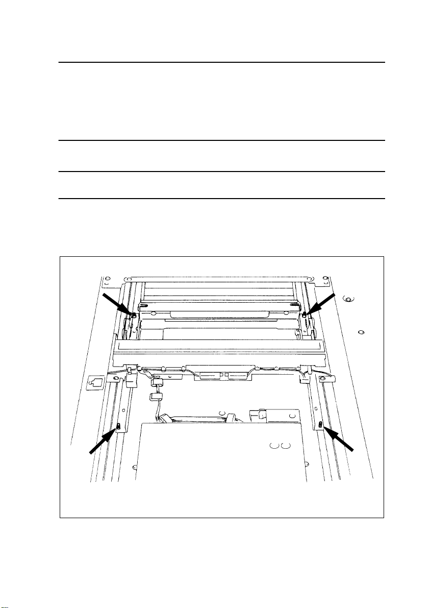
2. DISASSEMBLY AND REASSEMBLY
2-1. IDENTIFICATION AND REMOVAL OF EXTERIOR PARTS
4
3
2
1
5
10
20
9
8
11
6
7
1179D002AA
12
13
14
15
16
17
19
18
1179D003AA
D-3
Page 23

No. Name Removal Procedure
1 Front Door Open and remove the Front Door.
Raise Original Cover. → Open 1. → Remove 4 and 13. →
Remove 12. → Remove two magnet catches. → Remove two
2 Control Panel
3 Original Glass
4 Right Upper Cover Remove two screws that secure the Upper Right Cover.
5 Upper Right Cover
6 Lower Right Cover
7 Lower Front Cover
8 Lower Drawer
9 Middle Drawer
10 Upper Drawer
11 Rear Upper Cover
Original Width
12
Scale
13 Left Upper Cover Remove two screws that secure the Left Upper Cover.
14 Upper Left Cover
15 Middle Left Cover Remove two screws that secure the Middle Left Cover.
Lower Front Left
16
Cover
17 Multi Bypass Unit☞ D-15
Lower Rear Left
18
Cover
19 Rear Cover
Toner Collecting
20
Box Cover
screws that secure the Control Panel.
✽
Reinstallation Tip:
Fit the Control Panel into the rectangular hole in the panel
mounting bracket.
Remove 13. → Remove 12.
✽
Reinstallation Tip:
Fit the Original Glass into the groove in the Original Scale and
fit the glass into the Glass Restriction Plate.
Remove 4. → Remove four screws that secure the Upper Right
Cover.
Remove 4 and 5. → Remove five screws that secure the Lower
Right Cover.
Slide out the Lower Drawer. → Remove two screws that secure
the Lower Front Cover.
Slide out the drawer. → Remove the stopper. → Pull out the
drawer while slightly lifting it.
Remove Original Cover. → Remove two Hinge Covers. →
Remove 4 and 13. → Remove 21. → Remove 20. → Remove 5
and 14. → Remove six screws that secure the Rear Upper Cover.
Remove 13. → Remove two screws that secure the Original
Width Scale.
Remove 13. → Remove 16. → Remove 15. → Remove six screws
that secure the Upper Left Cover.
Remove two screws that secure the Lower Front Left Cover.
Remove two screws that secure the Lower Rear Left Cover.
Remove 21. → Remove seven screws that secure the Rear
Cover.
Remove one screw that secures the Toner Collecting Box Cover.
D-4
Page 24
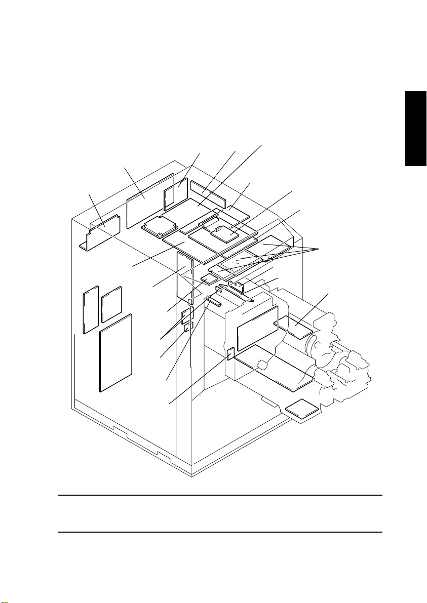
2-2. REMOVAL OF CIRCUIT BOARDS AND OTHER ELECTRICAL
COMPONENTS
• When removing a PWB or other electrical component, refer to “PRECAUTIONS FOR
HANDLING THE PWBs” and follow the corresponding removal procedures.
• The removal procedures given in the following omit the removal of connectors and
screws securing the PWB support or PBW.
• Where it is absolutely necessary to touch the ICs and other electrical components on the
PWB, be sure to ground your body.
PU2
PWB-LE
PWB-ID
PWB-C
PU1
HV1
PWB-K
PWB-S2
UN22
UN23
PWB-O
PWB-Y
PWB-G
PWB-A
PWB-LP
PWB-JD
UN19
PWB-IM
UN27
PWB-P
HV3
PWB-W
HV2
HV4
PWB-M1
1179D082CA
NOTE
When PWB-IM (Master Board) has been replaced, never fail to remove and reinstall IC6
(RAM) on the board.
D-5
Page 25

Symbol Name Removal Procedure
Remove the CCD Assy Cover. →
→
Remove 6 and 19. → Remove mounting
→
Remove 6 and 19. → Remove mounting
→
Remove cover. → PWB-M1
→
Remove Transfer Film. → PWB-O
→
PWB-A CCD Sensor Board
PWB-C IR Control Board
PWB-G SCP Board
PWB-ID Drive Board
PWB-IM Master Board
PWB-JD
PWB-K
PWB-LE
PWB-LP
PWB-M1
PWB-O
PH Control Board
(Digital)
Paper Take-Up
Board
Engine Power Supply Board
PHC Power Supply
Board
Automatic Adj.
Board
Paper Bonding Failure Detection Board 1Slide out Developing Unit.
Remove 13, 12, and 3.
Remove 5.
Board Assy.
Remove PWB-A with CCD Assy.
Remove 5.
Board Assy.
D-75
☞
D-74
☞
Remove 5.
Board Assy.
Remove 5.
Board Assy.
Remove 21 and 20.
bracket.
Remove 21 and 20.
bracket.
D-20
☞
Slide out Developing Unit.
Remove Shield Covers C and D. → Remove IR
→
PWB-A
→
Remove Shield Covers C and D. → Remove IR
→
Remove Shield Cover B. → PWB-C
→
Remove Shield Covers C and D. → Remove IR
→
Remove Shield Cover B. → PWB-IM
→
Remove Shield Covers C and D. → Remove IR
→
Remove Shield Cover B. → PWB-JD
→
PWB-K
→
PWB-LE
→
PWB-P
PWB-S2
PWB-W
PWB-Y
UN19
UN22
UN23 Humidity Sensor Remove 21 and 20.
UN27 Control Panel
PU1 DC Power Supply 1
PU2 DC Power Supply 2
HV1 High Voltage Unit 1 Remove 21 and 20.
HV2 High Voltage Unit 2
HV3 High Voltage Unit 3
HV4 High Voltage Unit 4
Paper Bonding Failure Detection Board
2
Tech. Rep. Setting
Switches Board
PC Drum Heater
Control Board
Failure Sensor Adj.
Board
Polygon Motor
Drive Board
Surface Potential
Detection Sensor
Slide out Developing Unit.
Remove 2.
Slide out PC Unit.
Slide out Transfer Unit.
Remove PWB Cover.
Remove 5.
Board Assy.
Remove 21 and 20.
Remove 2.
Remove 21 and 20.
mounting bracket.
D-74
☞
Slide out Transfer Unit.
Slide out Transfer Unit.
Slide out and remove Developing Unit.
Remove Developing Unit fixing bracket. → Remove Pre-
→
Image Transfer Corona Holder Assy.
Unit.
PWB-S2
→
Remove Shield Covers C and D. → Remove IR
→
Remove PH Upper Assy. → UN19
→
UN27
→
Remove cover. → HV4
→
D-6
Remove Transfer Film. → PWB-P
→
Remove PC Drum. → PWB-W
→
Remove Transfer Unit Cover. →
→
PWB-Y
→
Remove Toner Collecting Box. → UN22
→
Remove Toner Collecting Box. → UN23
→
Remove 6 and 19. → Remove Cover
→
Remove Cooling Fan Assy. → PU1
→
Remove mounting bracket. → HV1
→
Remove Transfer Unit Cover. → HV2
→
Remove Transfer Film. → HV3
→
Remove Drive Cover.
→
Remove Bk Developing
→
Page 26

2-3. MAINTENANCE SCHEDULE
• To keep the copier in good operating condition and ensure an extended service life of the
copier, it is recommended that the maintenance jobs described in this schedule be carried out.
Maintenance
PM Parts
Paper Take-Up/Feed Roll Assy
Paper Separator Roll Assy
Synchronizing Roller 30 ––3
Transport Roller 30 ––2
Vertical Transport Roller 30 ––6
Paper Dust Remo ver (Transport
Roller)
Paper Take-Up/ Transport
Fusing Roller
(Upper)
(Lower) – 60 11ZT53440 1 –
Upper Fusing Roller Bushing
(Front)
(Rear) – 180 25TU75710 1 –
Lower Fusing Roller Bushing
(Front)
(Rear) – 180 25TU75710 1 –
Cleaning Roller – 15 25TU53200 1 –
Fusing Entrance Guide 15 ––1
Fusing Roller Thermistor
(Upper)
(Lower) 15 ––2
Fusing Roller Thermostat
(Upper)
Fusing/Exit
(Lower) 15 ––2
Oil Regulating Blade 15 60 11ZT54060 1
Oil Collecting Blade 15 120 11UM54360 1
Paper Separator Fingers 15 ––––
Fuser Oil (✽2) –––
Oil Application Roller – 120 25TU54110 1 –
Oil Supply Roller – 120 25TU54100 1 –
Oil Filter – 15 25TU53610 1 –
Roller Drive Gear – 120
Paper Exit Roller – 120 11ZT47200 1 –
Developer Bk –
Developer Y/M/C –
Ds Roll 30 ––8
Developing
Toner Scattering Prevention
Seal 1 (Y Developing Unit only)
✽
1: According to the Life Counter.
✽
2: Add oil at 15K (based on A4 paper) or when an oil-empty condition is detected.
Cycle (K)
Clean Replace
60
(✽1)
(✽1)
180
(✽1)
60
180
(✽1)
30 120 25TU40370 1
– 60 11ZT53010 1 –
– 180 25TU75730 1 –
– 180 25TU75730 1 –
15 ––2
15 ––2
30
(✽1)
30
(✽1)
30 ––1
Part No. Qty Tools Used Ref. Page
25TU-4010 3
25TU-4020 3
25TU77890 1
25TU77970 1
25TU77980 2
– 1 –
– 3 –
Cloth, alcohol
Brush, vacuum cleaner
Cloth, alcohol
–
Cloth, alcohol
☞ D-21
☞ D-21
☞
D-24
☞
D-21
☞ D-21
☞ D-21
☞
D-30
☞ D-30
☞
D-30
☞
D-30
☞ D-30
☞ D-30
☞ D-38
☞
D-40
☞ D-40
☞
D-40
☞
D-40
☞ D-40
☞
D-34
☞ D-39
☞
D-33
☞ D-37
☞ D-34
☞ D-34
☞ D-39
☞ D-34
☞ D-34
☞ D-34
☞ D-44
☞ D-130
☞ D-130
☞ D-45
☞ D-45
D-7
Page 27

Maintenance
PM Parts
Toner Scattering Prevention
Plate (M/C/Bk)
Screw Assy Bushing
(Front)
(Rear) – 150 25TU75240 4 –
ATDC Sensor Window Y/M/C – 30 11ZT-3060 3 –
Air Filter – 60 25TU32120 1 –
Developing
Ozone Filter – (✽3) 25TU32110 1 –
Toner Collecting Box – (✽4) 11ZT-3210 1 –
Developing Unit Left Edge 15 ––4
Cycle (K)
Clean Replace
30 ––3
– 150 25TU75670 4 –
Part No. Qty Tools Used Ref. Page
Brush, vacuum cleaner
Cloth, vacuum cleaner
☞
☞
☞
☞
☞
☞
☞
☞
D-45
D-54
D-53
D-45
D-45
D-45
D-45
D-55
Shutter 60 ––4 Cloth
Hopper
PC Drum – 30 – 1 –
PC Drum Charge Corona Wire
Assy
Grid Mesh – 15 25TU25140 1 –
PC Drum Charge Corona
Housing
Ozone Filter (PC Drum Charge
Corona)
Cleaning Blade 15 25TU55400 1 –
Toner Antispill Seal 15 ––1
Pre-Cleaning Charge Corona
Wire
Pre-Cleaning Charge Corona
Housing
Main Erase Lamp 30 – 1
AIDC Sensor 15 – 1
Cleaner Side Seal
Parts around PC Unit
(Front)
(Rear) – 30 25TU55130 1 –
PC Bushing – 30 25TU55121 2 –
PC Drum Heater Terminal 30 ––1
Front Flange 30 120 25TU55240 1
Surface Potential Detection
Sensor
Toner Scattering Prevention
Seal 2 (under PC Drum Charge
Corona)
Slide Rail 30 ––4
Mirror (1st to 3rd) 15 ––3
Lens Filter 15 ––1
Optical
Original Glass 15 ––1
✽
3: 60K or 1 year
✽
4: At 75K or when a full Toner Collecting Box is detected
– 15 11UM25090 1 –
15 ––1 Cloth, water
(✽3) 25TU25370 1 –
15 30 25TU55190 1
15 ––1
– 30 25TU55310 1 –
30 ––1 Airbrush
30 ––1 Cloth
Brush, vacuum cleaner
Cloth, water
Cloth, alcohol
Cloth, alcohol
Cloth, alcohol
☞ D-56
☞
D-67
☞
D-65
☞
D-65
☞ D-65
☞ D-66
☞
D-67
☞
D-67
☞
D-64
☞
D-64
☞ D-66
☞
D-46
☞ D-67
☞
D-67
☞
D-67
☞ D-66
☞ D-67
☞ D-68
☞ D-68
☞ D-71
☞ D-71
☞ D-71
☞ D-71
D-8
Page 28

Maintenance
PM Parts
Window 1 (PH Upper Assy) 30 ––1
Window 2 (PH Upper Assy) 30 ––1
PH
Window 3 (PH Lower Assy) 30 ––1
Window 4 (PH Lower Assy) 30 ––1
Transfer Film –
Image Transfer Corona Wire 30 150 25TU21220 1
Image Transfer Cor ona Housing 30 ––1
Paper Separator Corona Assy 30 150 11UM-2600 1
Charge Neutralizing Corona
Assy (Inner)
(Outer) 30 150 11UM-2570 1
Static Charge Corona Wire 30 150 25TU21220 1
Static Charge Corona Housing 30 ––1
Paper Separator Finger 30 ––1
Transfer Drum Ring 30 ––2
Ozone Filter (Fusing, Image
Transfer)
Fur Brush Roller – 60 25TU46030 1 –
Fur Brush Roller Pressure
Spring
Fur Brush Roller Assy 30 ––1
Scraper Blade – 120 25TU45380 1 –
Sensor on Paper Bonding Fail-
ure Detection Board 1
Separating Failure Detecting
Sensor
Image Transfer
Sensor on Paper Bonding Failure Detection Board 2
Backup Blade 1 – 30 25TU21270 1 –
Static Charge Roller 15 ––1
Static Charge Roller Rubber
Roll
Static Charge Roller Scraper 15 150 25TU45380 1
Static Charge Roller Assy 15 ––1
Backup Blade 2 – 30 25TU21140 1 –
Oil Collecting Roller – 30 25TU27200 1 –
Static Charge Roller Clutch
Spring
Pre-Image Transfer Corona
Comb Electrode
Pre-Image Transfer Corona
Grid Mesh
Pre-Image Transfer Corona
Housing
✽
5: Perform “Jam Sensor” at the time of replacement.
✽
6: Apply heat-resistant grease (HP-500) at replacement.
Cycle (K)
Clean Replace
30
(✽5)
30 150 25TU-2580 1
– (✽3) 25TU32040 1 –
– 60 25TU46170 2 –
30 ––1
30 ––1
30 ––1
15 ––2
60
–
(✽6)
– 30 11ZT21020 1 –
15 30 11ZT21010
15 ––
Part No. Qty Tools Used Ref. Page
11UM20020 1 –
25TU20060 1 –
Brush, airbrush
Cloth, water
Cloth, alcohol
Brush, vacuum cleaner
Cloth
Cloth, alcohol
Brush, vacuum cleaner
Cloth, water
☞
D-19
☞
D-19
☞
D-19
☞
D-19
☞
D-88
☞
D-87
☞ D-87
☞ D-82
☞
D-86
☞ D-85
☞ D-86
☞
D-86
☞
D-80
☞ D-80
☞ D-79
☞ D-82
☞
D-82
☞
D-84
☞ D-82
☞
D-92
☞ D-80
☞
D-92
☞
D-92
☞
D-93
☞
D-93
☞
D-93
☞ D-93
☞ D-92
☞ D-80
☞ D-23
☞ D-70
☞ D-70
☞ D-70
NOTES
• K = 1,000 copies
• The contents of this maintenance schedule are subject to change without notice.
D-9
Page 29

2-4. REMOVAL OF UNITS
• This copier provides maintainability of each mechanical unit to shorten downtime at the
user’s premises.
• Note that replacement of a unit may call for readjustments or resetting of particular items.
Paper Exit Unit
Toner Hopper Unit
Paper Take-Up Unit
PC Unit
Multi Bypass Unit
Developing Unit
(1) Removal of the Toner Hopper Unit
Transfer Unit
Fusing Unit
1179D005AA
1. Slide out the Guide Rails.
3. Loosen the shoulder screws.
4. Toner Hopper Unit
2. Toner Antispill Plate
1154D289AA
D-10
Page 30
(2) Removal of the PC Unit
Remove the Toner Hopper Unit, unlock the Transfer Unit lever, and remove the Transfer Unit
Cover. Then, remove the PC Unit.
1. Developing Unit Cover
4. PC Front Frame Assy
B
5. Drum Holder
Fig. 2
3. PC Drum Charge Corona Assy
Fig. 1
While sliding the PC
Unit into the copier,
swing the drum in the
direction of the arrow
to avoid scratching it
on the Surface Potential Detection Sensor.
2. Slide out and then push down the
Developing Unit Pressure Lever.
6. PC Unit
Fig. 1
A
Fig. 2
At reinstallation, check that the Drum
Holder tabs fit into the slots. (If the
tabs do not fit in, turn the Drum
Holder.)
1154D291AA
1144D008AB
B
A
1154D290AA
1154D120AA
D-11
Page 31

NOTE
When mounting the PC Unit:
• Try to keep the PC Unit in the horizontal position.
• When turning the PC Unit upside down (at reinstallation), turn it counterclockwise as
illustrated below. Turning it clockwise could spill spent toner. If spent toner is spilled,
wipe the surface clean of toner.
Rear
Turn CCW.
Front
1144U039YA
D-12
Page 32

(3) Removal of the Developing Unit
After the Toner Hopper Unit has been removed, remove the Developing Unit.
1. Developing Unit Cover
2. Slide out and push down the
Developing Unit Pressure Lever.
4. Remove the Developing Unit.
Fig. 1
3. Slide out the Guide Rails.
Fig. 1 Developing Unit Mounting Position
Guide Rail Pin
Developing Unit
1179D006AA
Alignment Mark
1144D008AB
1154D121AA
NOTE
When the Developing Unit is slid out, the AIDC Sensor should be cleaned.
D-13
Page 33

(4) Removal of the Fusing Unit and Transfer Unit
NOTE
When removing the Fusing Unit, hold it upright to prevent the oil from being spilled.
1. Fusing Unit
Fig. 1
2. Transfer Unit
1179D007AB
Fig. 1 Unplugging the Connectors
1144D012AA
D-14
Page 34

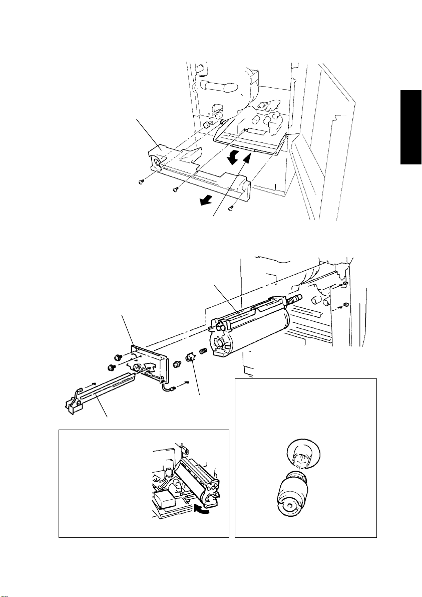
(5) Removal of the Multi Bypass Unit
3. Multi Bypass Unit
2. Connector
Fig. 1
1. Swing open.
1144D014AC
Fig. 1 Unplugging the Connector
D-15
1144D013AA
Page 35

(6) Removal of the Paper Take-Up Unit
After the Multi Bypass Unit has been removed, remove the Paper Take-Up Unit.
1. Mounting Bracket
2. Paper Take-Up Board Connector
Fig. 1
3. Slide out the
drawers and
the Transfer
Unit.
4. Paper Take-Up Unit
1154D123AB
Fig. 1 Unplugging the Connectors
Unplug the connectors indicated by the arrows.
Paper TakeUp Board
1179D008AA
D-16
Page 36

(7) Removal of the Paper Exit Unit
Paper Exit Unit
Fig. 1 Reinstalling the Paper Exit Unit
Try to move the unit in the direction of the
arrow at reinstallation.
Rear
1179D010AA
1179D009AA
D-17
Page 37

(8) Removal of the IR Board Assy
Front
Coaxial Cable
Fig. 1
Fig. 2
Fig. 2
1179D011AA
Fig. 2
Rear
2. Shield Cover C
1. Shield Cover D
3. IR Board Assy
Fig. 1 Removing and Reinstalling the Coaxial Cable
Removal
Coaxial
Coaxial Cable
Connector
Connector
Reinstallation
Coaxial Cable
Connector
Fig. 2 Removing and Reinstalling the IR Board Assy
NOTE
During the removal and reinstallation procedures, be
careful about the harnesses on both sides of the IR
Board Assy.
Front
Coaxial
Connector
Connector Coupling Axis
1179D012AA
Rear
1179D013AA
NOTE
Failure to connect the coaxial cable results in the Transfer Drum and other interior parts
being contaminated, seriously damaging the copier. Use these precautions when disconnecting and reconnecting the cable.
• Hold onto the main body of the connector of the coaxial cable and, aligning it properly
with the connector coupling axis, plug and unplug it as necessary.
• NEVER pull on the cable to plug and unplug the connector, as a damaged connector
could result.
D-18
Page 38

(9) Removal of the PH Assy
NOTES
• The PH Upper Assy and PH Lower Assy must be replaced as a set.
• Do not attempt to disassemble the PH Upper Assy or PH Lower Assy.
After the IR Board Assy has been removed, remove the PH Upper and Lower Assy.
Heat Conduction Sheet ×3
Fig. 3
3. PH Upper Assy
Figs. 2 and 3
1. Optical Cover
2. PH Lower Assy
Fig. 1
Fig. 1 PH Lower Assy
NOTES
• Hold the assy with your hands during
the procedure.
• Be sure to tighten screws to sufficient
torque. If they are loose, a periodically
(1 mm or less) uneven image could
result.
Window 3 Clean.
Window 4 Clean.
1144D021AA
1179D014AC
Fig. 2 PH Upper Assy
Window 1 Clean.
Window 2 Clean.
1154D128AC
D-19
Page 39

Fig. 3 Heat Conduction Sheet
NOTE
Without this sheet, a periodically (0.34 mm) uneven image could result. Make sure of
the following when reinstalling the PH Upper Assy.
• No part of the sheet is peeled off the mating surface.
• Replace a sheet if deteriorated.
Affix the Heat Conduction Sheet within the shaded areas shown below (indicated with
a stamp).
26 mm
26 mm
15 mm
30
2 mm
26 mm
(10) Removal of the PHC Power Supply Board
PHC Power Supply
Board
30
2 mm
15 mm
15 mm
2 mm
1179D070AB
2. PHC Power Supply Board
Assy
1. Drive Board Assy
1154D245AC
D-20
Page 40

2-5. PAPER TAKE-UP SECTION
(1) Cleaning and Replacement of the Paper Take-Up Roll, Feed Roll, Separator
Roll, and Paper Dust Remover
5. Paper Take-Up Clutch
Loosen set
screws. ×2
1154D129AC
4. Paper Take-Up
Roll Assy ×3
Clean or replace.
Fig. 2
3. Vertical Transport Guide
Plate ×3
2. Vertical Transport Guide
Plate Assy ×3
Fig. 1
Fig. 3
NOTE
Guide
Align the edge with the guide
plate end face at replacement.
6. Paper Dust Remover Assy
Fig. 3
Vertical Transport
Roller ×3
Clean.
Paper Dust Remover
Clean or replace.
1144D250AA
Transport Roller
Clean.
1. Slide out
the drawer
and remove
the Paper
Take-Up
Unit.
1154D130AB
Fig. 2
Where the Spring is Installed
1144D067AA
Where the Paper Take-Up Roll
Assy is installed:
The Paper Take-Up Roll shaft is on
the lever.
1144D068AA
D-21
Page 41

Fig. 1 Removing the Separator Roll Assy
Separator Roll Assy
Clean or replace.
Vertical Transport
Guide Plate Assy
Spring
1179D016AA
D-22
Page 42

(2) Removal of the Synchronizing/Static Charge Roller Assy
1. Transfer Cover Assy
2. Synchronizing/Static Charge Roller Assy
Fig. 1
Fig. 1 Reinstalling the Synchronizing/
Static Charge Roller Assy
Transfer Front Side
Plate Assy
Install the bushing.
Bring the Static Charge
Roller up in the direction
of the arrow.
Fig. 2 Static Charge Roller Clutch Spring
Coat the inner surface of the clutch spring with
heat-resistant grease (HP-500) when the clutch
spring has been replaced.
Ratchet
Cam
Transfer Rear Side
Plate Assy
Fig. 2
NOTE
Lever
Place the Static Charge
Roller lever under the
cam.
1154D132AC
Fig. 3 Grease Application
Instructions
Grease
1179D017AA
Cam
Clutch Spring
Change. Fig. 3
Gear
1154D288AA
D-23
Clutch Spring
Coat about-1-mmthick grease.
1154D287AA
Page 43

(3) Disassembly of the Synchronizing Roller Assy
3. Guide A
Fig. 1
Synchronizing Roller
Clutch
5. Guide B
Fig. 2
1. Synchronizing Roller Assy
Fig. 1 Where Guide A is Installed
0 ±1 mm
Guide A
Upper Synchronizing Roller
1144D085AA
Fig. 2 Where Guide B is Installed
There must
be a clearance.
Harness Guide
Fig. 3
2. Static Charge Roller Assy
4. Upper Synchronizing Roller
Clean.
1154D134AC
Fig. 3 Where Harness Guide is Installed
Install Guide B between the rollers (at
four places where the shaft is visible) as
illustrated below. Ensure the correct
orientation.
Roller
Guide B
Roller
1144D083AB
Align the clutch cord leader with the harness guide and snap the guide into position
until the catches contact the clutch face as
shown below.
Cord Leader
Catch
Harness Guide
Synchronizing
Roller Clutch
1144D084AA
D-24
Catch
Page 44

6. Lower Synchronizing Roller
Clean.
Milled end
Fig. 5
Fig. 5 Where Bushing and Springs are Mounted
Fit the spring over each protrusion as illustrated below.
1144D087AC
Spring
Protrusion in Rear
Side Plate
Check both front and rear.
Roller Motion Check
Protrusion in
Bushing
NOTE
The roller should be
returned to its original
position by the spring
tension when pressed
in the direction of the
arrow.
1144D088AA
D-25
Page 45

(4) Removal of the Drawer Lift-Up Motor Assy
Remove each drawer, then remove the Drawer Lift-Up Motor Assy.
Middle Drawer Lift-Up
Motor Assy
Lower Drawer Lift-Up
Motor Assy
(5) Disassembly of the Multi Bypass Unit
Upper Drawer Lift-Up
Motor Assy
1144D180AA
2. Vertical Transport
Door Assy
1. Cover
1154D135AC
D-26
Page 46

5. Manual Feed Paper
Pick-Up Solenoid Assy
Fig. 3
3. Loosen screws. Move in
the direction of the arrow.
4. Multi Bypass Table Assy
Figs. 1 and 2
Fig. 1 Where Multi Bypass Table Assy is Installed
NOTE
The pivot (in the rear) should be moved in the direction of
the arrow when secured.
1179D018AA
Fig. 2 Position of Connector
1154D137AC
Pivot (rear)
Pivot (front)
Multi Bypass Table
1144D174AA
Fig. 3 Where Manual Feed Paper Pick-Up Sole-
noid Assy is Installed
Paper Take-Up Roll Idler Shaft
Lever
NOTE
1144D175AA
The Paper Take-Up Roll idler shaft
must be positioned with reference to
the Manual Feed Paper Pick-Up Solenoid lever as illustrated above.
D-27
Page 47

9. Manual Feed Paper
Take-Up Clutch
Fig. 4
7. Loosen set screw.
6. Spring
8. Mounting Bracket Assy
1154D138AD
Fig. 4 Manual Feed Paper Take-Up Clutch Installed Position
0.2 ~ 1.0 mm
Slide the mounting
bracket assy in the direction of the arrow to eliminate the play and,
ensuring that there is a
clearance of 0.2 to 1.0
mm from the gear,
secure the Manual Feed
Paper Take-Up Clutch in
position.
Manual Feed Paper
Take-Up Clutch
D-28
Mounting
Bracket Assy
1144D177AA
Page 48

11. Paper Take-Up Roll Assy
Fig. 5
10. Separator Guide Assy
1154D139AE
Fig. 5 Where Spring is Installed
NOTE
Hook the end of the spring in
the slit in the guide plate
(upper).
Guide Plate (upper)
1144D179AA
D-29
Page 49

2-6. FUSING/EXIT SECTION
(1) Replacement of the Upper and Lower Fusing Roller Bushings and Upper and
Lower Fusing Rollers
3. Upper Fusing Roller Heater
Lamp fixing bracket
2. Rear Face Cover
Fig. 1
Rear
4. Lower Fusing Roller Heater
Lamp fixing bracket
5. Upper Fusing Roller Heater
Lamp fixing bracket
Fig. 2
1. Loosen the Fusing
Unit pressure adjusting screws. ×2
1179D019AA
7. Upper and Lower Fusing
Roller Heater Lamps
Fig. 1 Where Harnesses
are Wired
Lamp wires
Thermistor wires
Wire color white ↔ white
1179D021AA
Wire color red ↔ red
Fig. 2 Connectors
Front
1179D020AA
6. Lower Fusing Roller Heater
Lamp fixing bracket
D-30
1144D024AA
Page 50

9. Top Cover
11. Upper Frame Assy
10. Oil Pump
1179D080AA
Rear
8. Swing open the Paper
Separator Fingers Assy.
D-31
Page 51

Upper Fusing Roller Bushing ×2
Replace. Fig. 3
Short milled surface
Bearing
Fig. 4
Rear
13. Upper Fusing Roller
Replace.
Front
Fig. 3
Do not confuse the bushing for the
front side with that for the rear side.
One for the front
side = 17 mm
One for the rear
side = 12.5 mm
1144D031AA 1144D030AA
12. Holding plate ×2
1144D029AD
Fig. 4
Where Bearings are Installed
Frame
Front Rear
D-32
Page 52

15. Fusing Entrance Guide
Fig. 5
16. Lower Fusing Roller
Replace.
Lower Fusing Roller Bushing ×2
Replace. Fig. 6
Bearing
14. Harness cover
Fig. 7
Front
Rear
Paper Separator Finger ×10
Clean.
1154D224AE
Fig. 5 Installing Fusing Entrance Guide
NOTE
When mounting the Fusing Entrance Guide, make sure that the guide is in complete
alignment with the positioning plates, having no clearance from, or overlap with, the
positioning plates.
Fusing Entrance Guide
Positioning Plate
Fig. 6
Do not confuse the bushing for
the front side with that for the
rear side.
Positioning Plate
Fig. 7
Bearings (front and rear) installation positions
Flange
1154D295AA
One for the front
side = 17 mm
A
One for the rear
side = 12.5 mm
1144D031AA
Lever
Frame
1144D033AA
D-33
Page 53

(2) Replacement of the Oil Application Roller, Oil Supply Roller, Roller Drive Gear,
and Oil Regulating Blade
1. Top Cover
4. Bushing
Fig. 2
Holding bracket
(rear)
B
A
B
2. Holding bracket
(front)
3. Spring ×2
A
Fig. 1
5. Oil Application Assy
Fig. 1 Spring Installation Positions
Hook the springs to - and - .
A A
B B
Where the spring is installed:
Pass the longer hook through the rectangular hole and hook it in the round hole
from the above.
1144D039AA
D-34
1179D023AA
Fig. 2 Bushing (both front and rear)
Turn the bushing as
illustrated and remove.
1144D038AA
Page 54

8. Spring ×2
Fig. 3
Straight pin
6. Roller drive gear
Replace.
Fig. 4
Fig. 3 Where Spring is Installed
D-cut face
7. Round shaft
1154D140AB
NOTE
Do not turn the gear in the
direction of the arrow.
1154D141AB
Fig. 4 Where Gear is Mounted
E-Ring
Insert the straight pin
into the round shaft.
Then, mount the gear
and secure it in position with the E-ring.
Gear
Straight
Pin
1144D042AA
D-35
Page 55

10. Oil Application Roller
Replace.
Rear
D-cut face
9. Roller drive gear
Replace.
1179D024AA
14. Oil Regulating Blade Assy
NOTE
Handle with care not
to damage the blade
edge.
Front Side Plate Assy
11. Roller drive gear
Replace.
12. Oil Supply Roller
Replace.
13. Oil Pick-Up Roller
1154D142AB
D-36
Page 56

15. Holding plate
NOTE 1
Face the blade as shown. Never mind
about the front and back sides of the
blade.
Check holes
16. Oil Regulating Blade
Clean or replace.
NOTES 1 and 2
NOTE 2
At reinstallation, visually check that:
• The blade is on the dowel by checking
through the check hole.
• The blade is not waved.
Support plate
(3) Adding Fuser Oil
1154U067AA
1154U006AA
1144D045AA
1. Fit the spout to the oil can.
2. Remove the cap from the Fuser Oil Tank and
pour oil into the tank.
3. Fill the tank with care not to exceed the
▼
marking on the MAX. label.
D-37
Page 57

(4) Replacement of the Cleaning Roller
1. Top cover
1154D143AC
2. Cleaning Roller Assy
Bushing ×2
4. Cleaning Roller
Replace.
NOTE
1144D035AC
D-38
3. Mounting bracket
NOTE
NOTE
The spring should be fit into the Ugroove in the bushing (both for the
front and rear).
Spring
U-Groove
1144D036AA
Page 58

(5) Replacement of the Oil Collecting Blade and Oil Filter
3. Oil Filter
Replace.
Rear
2. Oil Collecting Blade Assy
Fig. 2
1. Left Side Face Cover
Fig. 1
Fig. 1 Installing Left Side Face Cover
NOTE
The frame should be caught by the
tab of the cover (at two places).
Frame
1179D026AB
Cover
Fig. 2 Disassembling and Reassembling Oil Collecting Blade Assy
Oil Collecting Blade
Clean or replace.
Support plate
NOTE
1154D146AA
NOTE
At reinstallation, ensure that the face of the blade
marked with “WORKING EDGE” is on the Fusing
Roller side. Make also sure that the blade is properly on the dowels.
D-39
1154D145AB
Holding plate
Page 59

(6) Cleaning of the Fusing Entrance Guide, Upper and Lower Fusing Roller Ther-
mistors, and Upper and Lower Fusing Roller Thermostats
1. Top Cover
3. Upper Fusing Roller Thermostat
Clean. NOTE 1
2. Upper Fusing Roller
Thermistor
Clean.
4. Lower Fusing
Roller Thermistor
Clean.
6. Fusing Entrance Guide
Clean.
5. Lower Fusing Roller Thermostat
Clean. NOTE 1
NOTE 1
Try to slide the assy
upward at reinstallation.
NOTE 2
1154D148AA
NOTE 2
The tab should be fit in position at reinstallation.
D-40
Page 60

(7) Disassembly of the Oil Pump Assy
1. Top Cover
2. Oil Pump Assy
Figs. 1 and 3
NOTE
Front
NOTE
Be careful about oil spillage when the tube
is removed from the oil tank.
1154D149AA
Fig. 1 Disassembling Oil Pump Assy
Longer part
Longer part
Holder ×2
Lower oil tube
Support plate
Clamp ×2
Oil pump
D-41
Holder
1154D292AA
Page 61

Fig. 2 Oil Pump Installation Position
NOTES
• The oil pump should be located in the space between the oil tank rib and wall (as
shown at A in the illustration below).
• Secure the oil pump so that the distance between the radius part of the oil pump and
frame measures 1 ±1 mm (as shown at B in the illustration below).
Frame
Clamps
P
Rib
B
1 ±1 mm
P (top view)
Wall
Oil pump
Oil tank
A
1179D078AA
D-42
Page 62

Fig. 3 At Replacement of Oil Pump
1144U105AA
1144U106AA
1. Insert the syringe into the lower oil tube
and draw about 5ml of oil.
2. Attach the rubber tube contained in the
accessories box to the syringe.
3. Attach the rubber tube to the lower oil
valve and inject the 5ml of oil into it.
1144U107AA
1144U108AA
4. Remove the rubber tube and syringe
and plug back in the lower oil tube of the
Oil Pump Assy.
NOTE
Do not turn any of the knobs, gears, or
rollers of the Fusing Unit when the oil
tank is empty. If anything is turned in
the unit when the tank is empty, the
pump will lose its priming oil and may
not be able to pump afterwards.
D-43
Page 63

(8) Replacement of the Exit Roller
1. Upper Paper Exit
Guide Plate Assy
4. Exit Roller
Replace.
A
Spring (front)
Fig. 1
Bushing (front)
3. Front frame
Spring (rear)
Fig. 1
Place the harness
inside the bend.
B
Bushing (rear)
2. Lower Paper Exit
Guide Plate
Spring
catch
Fig. 1 Where Spring is Installed
Hook the
spring end.
1179D028AB
D-44
1179D027AC
Hook the spring at A
and B of the front and
rear frame.
Page 64

2-7. DEVELOPING UNIT
(1) Replacement of the ATDC Sensor Window
NOTE
When the ATDC Sensor window
has been replaced, check that
the window makes full contact
with the terminal by testing for
conductance (marked with
arrows in the illustration).
(2) Cleaning of the Ds Rolls, Toner Scattering Prevention Seal 1, and Toner Scat-
tering Prevention Plate
(3) Replacement of the Toner Collecting Box, Air Filter, and Ozone Filter
NOTE
2. ATDC Sensor window
Replace.
1. ATDC Sensor Assy
2. Ds Roll ×2
1. Toner Scattering Prevention Seal 1 Clean.
(Y Developing Unit only)
Toner Scattering Prevention Plate Clean.
(M/C/Bk Developing Unit)
1144D094AA
Clean.
1144D095YA
1. Toner Collecting Box
Replace.
4. Mounting bracket
5. Ozone Filter
Replace.
3. Air Filter
Replace.
2. Cover
1144D078YB
D-45
Page 65

(4) Removal of the Bk Developing Unit
2. Pre-Image Transfer Corona Holder Assy
Fig. 1
4. Bk Developing Unit
Fig. 2
1. Drive cover
A
B
Fig 3
3. Fixing bracket
Fig. 1 Removing Pre-Image Transfer Corona
Holder Assy
Free the Pre-Image Transfer Corona Holder
Assy and then move it aside in the direction of
the arrow.
A
B
1179D029AA
Fig. 2 Unplugging Bk Developing Unit
Connector
1144D146AA
Fig. 3
AIDC Sensor
Clean.
Pre-Image Transfer Corona Holder Assy
1179D030AB
1179D031AA
D-46
Page 66

(5) Removal of the Y, M, and C Developing Units
5. C Developing Unit
Fig. 1
2. Fixing bracket
4. M Developing Unit
Fig. 1
3. Y Developing Unit
Fig. 1
1. Drive cover
1154D152AC
Fig. 1 Unplugging Connectors
1154D153AC
D-47
Page 67

(6) Disassembly of the Developing Unit
5. Lid assy
6. Blade assy
3. Seal ×2
Fig. 1
4. Toner Scattering
Prevention Plate Assy
Washer
Shoulder screw
1. Mounting
bracket assy
Fig. 1 Seal Affixing Specifications
(Rear) (Front)
Seal ×2
2. Duct assy
D-48
1179D032AA
1144D151AA
Page 68

7. Remove the Developing Unit drive mechanism (in the rear).
Bearing
Developer Supply Clutch
Fig. 2
Bearing
Fig. 2 Where Developer Supply Clutch is Installed
Lock
1154D155AB
Developer Supply
Clutch
NOTE
The clutch lock should be fitted to the mini-saddle mount on the drive side plate.
D-49
1144D153AA
Page 69

8. Remove the drive mechanism for the Sleeve/Magnet Roller and Developer Supply
Roller.
Seal
Fig. 3
Holding plate
Collar
Ds Roll (rear) (yellow)
Fig. 3 Seal (Rear) Affixing Specifications
Seal
1154D156AB
1154D157AA
D-50
Page 70

9. Remove the parts (at the front) that secure the Sleeve/Magnet Roller.
NOTE
Remove the supply
port for the C Developing Unit.
Seal
Fig. 6
Spring
Bushing holder assy
Bushing
Fig. 5
Ds Roll (front) (white)
Fig. 4
Bias terminal
1144D156AB
Fig. 4 Ds Roll (front) Orientation
Sleeve/Magnet Roller
NOTE
Orient the roll as shown above.
Positional relation between Ds roll (front)
and seal
Seal
1144D159AA
D-51
Fig. 5 Where Spring is Installed
Bushing
Bushing holder
Spring
1144D157AA
NOTE
The spring should fit in the
bushing holder groove.
Fig. 6 Seal (Front) Affixing Specifications
Seal
1144D158AA
Page 71

10. Remove the Sleeve/Magnet Roller and Developer Supply Roller.
NOTE
Developer Supply Roller
Sleeve/Magnet
Roller
Bearing
Spring
Fig. 7
NOTE
Notice the black paint applied to the C
and Bk Developing Units and red paint
to the M and Y Developing Units.
Paint
1154D159AA
Fig. 7 Where Spring is Installed
Spring
NOTE
The spring should fit in the chamber
groove.
D-52
1154D158AA
Bearing
1144D160AA
Page 72

11. Remove the screw assy bushing (in the rear).
Screw assy bushing (rear)
Fig. 8 Replace.
1144D162AB
Fig. 8 Precautions for Installing Bushing
Mount the bushing onto the screw shaft while
turning it slightly in the direction of the arrows.
Bushing
1144D163AA
D-53
Page 73

12. Remove the screw assy bushing (at the front).
Screw assy bushing (front)
Replace.
1154D160AB
D-54
Page 74

(7) Cleaning along the Left Edge of the Developing Units
Developing Units left
edge (Y, M, C, Bk)
Clean.
1144D095YA
PC Drum
Developing Units
D-55
1144D345YA
Page 75

2-8. TONER HOPPER
(1) Cleaning of the Shutters
Toner Hopper
Unit
Shutters Clean.
Fig. 1
Fig. 1 Cleaning Shutters
1154D163AC
Shutter
Clean.
Open the shutter.
1144D182AB
D-56
Page 76

(2) Disassembly of the Toner Hopper Unit
1. Hopper cover assy
2. Cover
NOTE
Use care not to deform
these parts.
D-57
1154D164AC
Page 77

5. Timing pulley
4. Tension plate assy
3. Spring
6. Timing belt
7. Timing pulley
D-58
1154D165AD
Page 78

8. Remove the gears.
Gear ×4
Fig. 1
A
Spacer
Gear
Fig. 2
D
B
C
Spacer
1179D035AA
Fig. 1 Where Gears are Installed
Gears A and C
Boss end
Gears B and D
Frame
Boss end
Frame
1179D036AA
Fig. 2 Where Gear is Installed
Boss end
1144D193AA
Bushing
NOTE
Before mounting the bushing and
gear on the round shaft, check that
the bushing on the opposite end is
not out of position. (If the bushing is
out of position, reinstall it.)
D-59
Page 79

Ground plate
NOTE 1
Ground plate
NOTE 1
10. Conveying Pipe Assy
Figs. 3 and 4
9. Gear mounting
bracket assy
NOTE 1
The Conveying Pipe Assy should be installed between the ground plate and Toner
Hopper Unit.
11. Toner Transport
Motor Assy
1179D037AB
Ground plate
Ground
plate
1154D168AC
D-60
Page 80

Fig. 3 Connector Positions
Fig. 4 Removing Toner Replenishing Motors
M Toner Replenishing Motor
1154D169AB
Y Toner Replenishing Motor
C Toner Replenishing Motor
1179D038AA
D-61
Page 81

12. Bk Motor Assy
Ground
plate
NOTE 2
1154D170AB
NOTE 2
The Bk Motor Assy should be installed between the ground plate and Toner Hopper Unit.
1154D171AC
D-62
Page 82

13. Toner Transport Motor (Bk) Assy
14. Round
shaft assy
Fig. 5
15. Toner Replenishing
Motor (Bk)
1144D191AA
Fig. 5 Round Shaft Assy Mounting Position
To mounting bracket
1144D192AA
D-63
Page 83

2-9. PARTS AROUND THE PC UNIT
(1) Removal of the PC Drum Charge Corona Assy and Pre-Cleaning Charge
Corona Assy
2. P re-Cleaning Charge
Corona Assy
1. PC Drum Charge Corona Assy
(2) Cleaning and Replacement of the Pre-Cleaning Charge Corona
3. Pre-Cleaning Charge Corona wire
Clean or replace.
1. Holder cover
Front
4. Pre-Cleaning Charge Corona housing
Clean.
2. Holder cover
D-64
1154D172AB
1154D173AA
Page 84

(3) Cleaning and Replacement of the PC Drum Charge Corona Assy
1. PC Drum Charge
Corona grid mesh
Replace.
NOTE
2. Front cover
Front
4. PC Drum Charge Corona
wire assy
Replace.
Fig. 1
6. PC Drum Charge
Wire Cleaning
Motor
5. Cover
3. Rear cover
7. PC Drum Charge
Corona housing
Clean.
NOTE
Wipe the grid mesh in the
direction of the mesh.
1154D174AC
Fig. 1 PC Drum Charge Corona Wire Installation Position
Hook the end
onto the cutout.
Fit the wire into
the cutout.
Front
Fit the wire into the
shaded area.
Rear
D-65
1154D175AE
Page 85

(4) Replacement of the Ozone Filter (PC Drum Charge Corona) and Cleaning of the
Main Erase Lamp
3. Slide out the PC Unit.
2. PC Front Frame Assy
Fig. 1 NOTE
5. Ozone Filter (PC Drum Charge
Corona)
Replace. Fig. 2
7. Main Erase Lamp
Clean.
4. Cover
1. PC Drum Charge Corona
Assy
NOTE
When removing the PC Front Frame
Assy, first unlock the Transfer Unit
lever and the Developing Unit lock
lever.
Fig. 1 Cleaning PC Drum Heater Terminal
PC Drum Heater terminal
Clean.
1144D092AA
6. Lamp holder
1154D280AB
Fig. 2 Ozone Filter Removal/Reinstallation
Direction
Ozone
Filter
Air Filter
1144D259AA
Make sure that the Air Filter is on the
underside at reinstallation.
D-66
Page 86

(5) Disassembly of the PC Unit
2. PC Drum
4. PC Drum Heater Control Board
Replace. NOTE
C
F
B
E
9. Toner Antispill Seal
Clean.
A
D
A
C
B
3. Front flange
Clean or replace.
D
1. PC bushing ×2
Replace.
6. Pre-Cleaning Charge Corona
7. Cleaner side seal ×2
Replace.
NOTE
When the PC Drum and Cleaning Blade have been replaced:
5. Cleaning Blade
Replace. NOTE
F
E
8. Guide plate
1154D176AB
1. Apply a thin
coating of
toner to the top
of the PC
Drum.
1144U039AA
2. Retracting the
Cleaning Blade,
turn the PC Drum
in the direction of
A (backward) until
the surface, to
which toner has
been applied,
reaches the
Cleaning Blade.
A
1144U040KA
3. Press the
D-67
Cleaning Blade
against the surface of the PC
Drum and turn
the PC Drum in
the direction of
B (forward)
three complete
turns.
B
1144U041AA
4. Check that no
toner has
spilled over part
C shown below.
If any has
spilled, retract
the Cleaning
Blade and
clean the surface.
PC Drum
Part
C
Cleaning Blade
1144D324AA
Page 87

(6) Cleaning of Toner Scattering Prevention Seal 2 and the Surface Potential Detec-
tion Sensor
After the PC Unit has been removed, clean Toner Scattering Prevention Seal 2 and
the Surface Potential Detection Sensor
Surface Potential
Detection Sensor
Clean. NOTE
Toner Scattering
NOTE
The Surface Potential Detection Sensor
is fragile. Be careful when cleaning it.
Prevention Seal 2
Clean.
1154D177AA
D-68
Page 88

(7) Removal of the PC Shaft Ground Plate
4. PC shaft ground plate
NOTE
Pull out the ground plate
with care not to drop it
inside the cover plate.
Spacer
Cover plate
2. Flywheel
NOTE
Handle the flywheel with
care as it is heavy (weighing about 5 kg).
3. Pipe
1. Mounting
bracket
1154D178AD
D-69
Page 89

(8) Cleaning and Replacement of the Pre-Image Transfer Corona Assy
1. Drive cover
2. Pre-Image Transfer
Corona Assy
Fig. 1
1179D040AA
Fig. 1 Disassembly of the Pre-Image Transfer Corona Assy
1. Pre-Image Transfer Corona
grid mesh
Clean or replace. Fig. 1
Holder
NOTE
Move the holder in the
direction of the arrow
2. Cover ×2
and remove the Comb
Electrode.
A
4. Pre-Image Transfer
Corona housing
Rear
Clean.
3. Pre-Image Transfer Corona
Comb Electrode
Clean or replace.
Fig. 2 Pre-Image Transfer Corona Grid Mesh Orientation
Rear Front
Narrower Wider
D-70
NOTE
Turn part A of the
holder in the direction
of the arrow and
remove the grid mesh.
1179D041AB
1179D022AA
Page 90

2-10. OPTICAL SECTION
(1) Cleaning of the Original Glass
Original Glass Clean.
(2) Cleaning of the 1st to 3rd Mirrors, Slide Rails, and Lens Filter
1st Mirror Clean.
1179D042AA
Slide Rail ×4
Clean.
3rd Mirror
Clean.
2nd Mirror
Clean.
Lens Filter
Clean.
1179D043AA
D-71
Page 91

(3) Disassembly of the Optical Section
2. CCD Assy cover
7. CCD Assy
Fig. 2
6. Fixing
bracket
Fig. 1
1. Scanner
3. Shield Cover D
4. Shield Cover C
Fig. 1 Installing Fixing Bracket
Fixing bracket
Seal
Ferrite Core
5. IR Board Assy
1179D079AB
D-72
1179D044AD
Fig. 2 CCD Assy Harness
Wiring
Wiring saddles
CCD Assy harnesses
1179D045AB
Page 92

(4) Disassembly of the Scanner
Fig. 1 Case Orientation Fig. 3 Exposure Lamp Orientation
Shorter
Longer
1144D126AA
Fig. 2 Where Exposure Lamp is Installed
Lamp protruding navel
orientation
90°
Navel
NOTE
Navel should be
located within
the 90° range.
1144D127AA
2. Exposure Lamp
Figs. 2 and 3
Marking
70V150W
Front Rear
1144D128AA
1. Terminal
Fig. 1
4. Thermostat
D-73
3. Cover
1154D180AA
Page 93

(5) Removal of the Scanner Drive Cables
y
3. Control panel
4. Panel mounting
bracket
7. Drive Board Assy
Fig. 1
2. Cover
1. Cover
5. Mounting bracket
1179D046AA
8. DC Power Supply 2 Ass
Fig. 1
D-74
6. Cover mounting bracket
1179D047AA
Page 94

Fig. 1 Connectors of the Drive Board and DC Power Supply 2
Drive Board
10. Cooling Fan Assy
9. SCP Board Assy
Fig. 2
DC Power Supply 2
1179D048AA
Fig. 2 Connectors of SCP Board
1179D049AA
SCP Board
1179D050AB
D-75
Page 95

15. Timing belt
12. ADF mounting
bracket assy
13. Spring
14. Scanner Motor Assy
Fig. 3
Fig. 3 Installing Scanner Motor Assy
1. Timing belt
3. Temporarily secure the
Scanner Motor Assy.
5. Secure the Scanner
Motor Assy firmly in
position.
2. Route the harness through the wiring saddle underneath the Scanner Motor Assy.
11. Mounting
bracket ×2
4. Spring
1179D051AA
1179D052AA
D-76
Page 96

19. Pulley
16. Scanner
23. Cable pulley
Rear
18. Cable holding jig ×2
Shaft
NOTE
Front
22. Collar
21. Cable pulley
17. Scanner fixing bracket ×2
20.Cable tension spring ×2
NOTE
Make sure that there is no play in the drive shaft when screwing the cable
pulleys.
1144D136AA
D-77
Page 97

(6) Winding of Scanner Drive Cables
2nd/3rd Mirrors Carriage
Cable pulley ×2
Figs. 1 and 2
Cable tension spring
Fig. 1 Winding Cables
Wind cable A five turns clockwise and
cable B three turns counterclockwise.
Then, fit the cable holding jig at the position shown in Fig. 2.
A
B
Fig. 2 Cable Holding Jig Position
Cable holding jig
A
B
1144D138AB
1144D137AA
45°
1144D140AB
D-78
Page 98

2-11. TRANSFER UNIT
(1) Replacement of the Ozone Filter
(2) Removal of the Paper Separator Corona
Ozone Filter (Image
Transfer, Fusing)
Replace.
1154D182AC
Paper Separator Corona
Fig. 1
1154D183AB
Fig. 1 Where Paper Separator Corona is
Installed
Corona unit rail
NOTE
Part (A) should be
in the rectangular
hole in the corona
unit rail.
A
D-79
1154D184AB
Page 99

(3) Cleaning of the Paper Separator Finger, Transfer Drum Ring, and Separating
Failure Detecting Sensor
Separating Failure
Detecting Sensor
Clean.
Paper Separator Finger
Clean.
(4) Disassembly of the Transfer Unit
4. Oil Collecting Roller
Figs. 2 and 3
Transfer Drum Ring ×2
Clean.
1179D053AA
3. Fur Brush Assy
D-cut face
Gear
Fig. 2
2. Fur Brush Pivot Shaft Assy
D-80
1. HV Board Assy
Fig. 1
1154D186AA
Page 100

Fig. 1 Connectors of HV Board
Paper Separator
Fur Brush (red)Fur Brush (white)
Fig. 2 Flat Spring in Ratchet Tooth
Flat spring
Charge Neutralizing (inner)
Charge Neutralizing (outer)
NOTE
The flat spring should fit
into one of the ratchet
teeth.
1154D188AB
Orientation
1144D099AA
Fig. 3 Removing and Reinstalling Oil Collecting Roller
Oil Collecting Roller
Roll
Where E-ring is to
be snapped in
Where E-ring is to
be snapped in
D-81
Ratchet
Replace.
Roll
1154D187AA
 Loading...