

Page 1
3. ADJUSTMENTS
NOTE
After the copier has exited the Service mode, be sure to turn OFF and ON the Power
Switch to let the copier run an image stabilizer sequence.
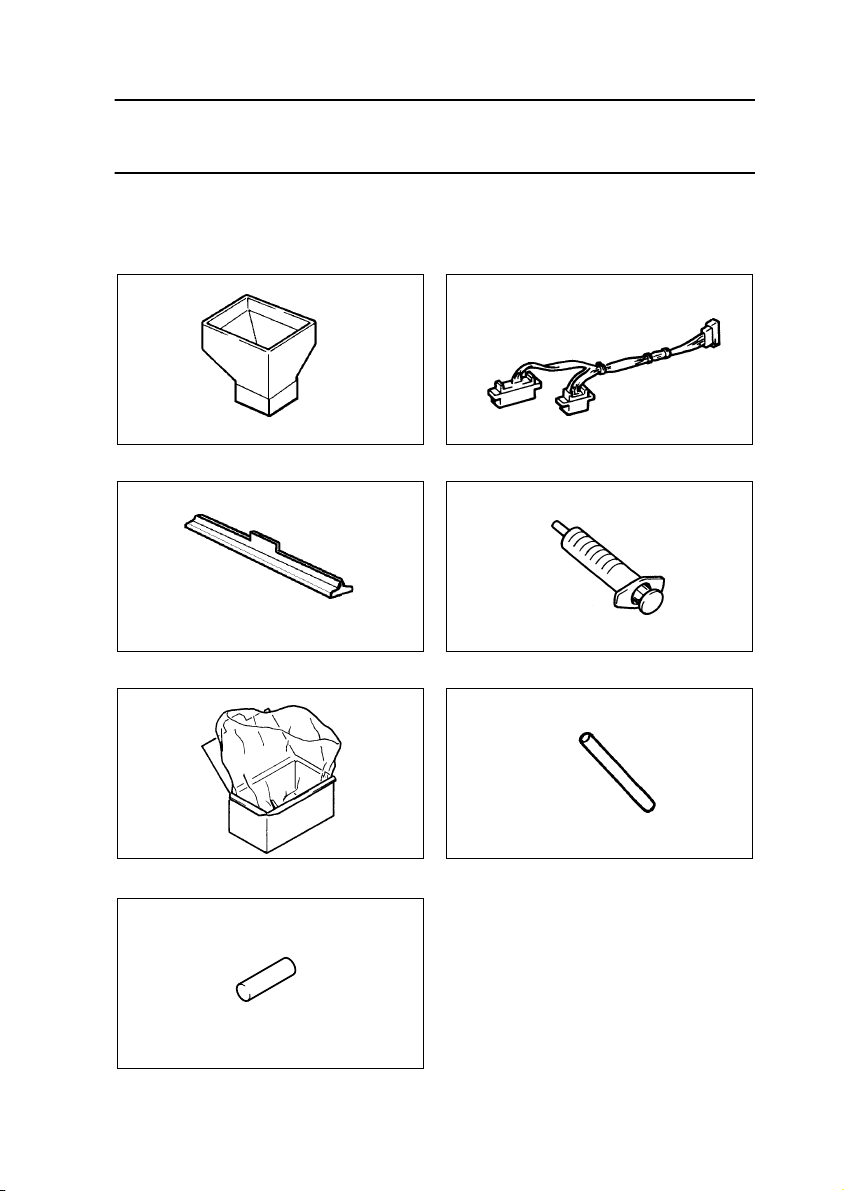
3-1. JIGS AND TOOLS USED
(1) Tools for Setting-up and PM
Part No. 25TU00460 Part No. 11ZT00440
× 4
1144D228YA
1
Developer Chute
✽
Jumper Harness
Part No. 25TU00470 Part No. 25TU00450
× 4
1144D269YA
Mag. Roller Shield Fuser Oil Syringe
Part No. 25TU00330 Part No. 25TU00370
1154D209AA
Developer Collecting Bag & Box Rubber Tube
✽
Part No. 11UM01250
1: New jumper harness (Part No.
11ZT00440) can use both 7823 and
7832.
× 2
But current jumper harness (Part No.
11UM00440) can use only for 7823.
1154D217AA
1154D211AA
1154D216AA
Pin
1154D261AA
D-94
Page 2

(2) Miscellaneous Jigs
Part No. 11ZT00540 Part No. 11ZT00040
1144D229AA
4002D503AA
Db Gap Adjusting Jigs Cable Holding Jigs
Part No. 25TU00400
Part No. 25TU00340
25TU00410
1144D235AA
1144D326AA
Scanner/Mirrors Carriage Positioning Jigs Transfer Adjusting Jig
Part No. 25TU00420 Part No. 25TU00350
1144D233AA
1144D231AA
AIDC Sensor Positioning Jig Interlock Switch Actuating Jig
D-95
Page 3
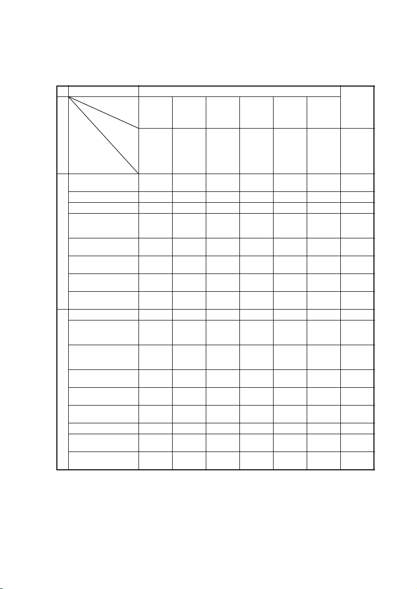
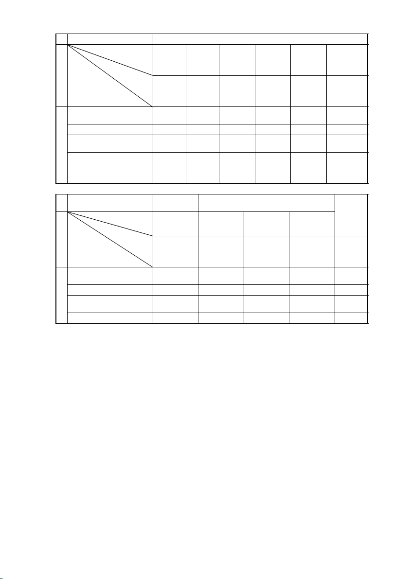
3-2. ADJUSTMENT REQUIREMENTS FOR CLEANING/REPLACE-
MENT OF EACH PART
When any of the jobs listed in the Parts List column is performed (replacement or cleaning),
make the adjustments in numerical order 1, 2, ...
Job Type Developer Change
Job item Developer
Check
Use jig. Use jig. Reference
Section
Parts List
Developing Unit replacement
Developer change 2 1 3 4 5 6 7
Ds rolls cleaning ––(1) (1) –––
Toner Scattering Preven tion Plate (M, C, Bk)
cleaning
Toner Scattering Preven tion Seal 1 (Y) cleaning
Developing Unit
ATDC window replacement
ATDC Adj. Unit replacement
High Voltage Unit 4
replacement
PC Drum replacement ––12––3
PC Drum Charge
Corona Assy replacement
PC Drum Charge
Corona wire/grid cleaning/replacement
PC Drum Charge
Corona housing cleaning
Cleaning Pad replacement
Main Erase Lamp cleaning
PC Unit and associated parts
AIDC Sensor cleaning ––12–– 3
Surface Potential Detection Sensor cleaning
Toner Scattering Preven tion Seal 2 cleaning
✽
(1) Check.
Developer
Filling
Discharge
1 – 23456
––(1) (1) –––
––(1) (1) –––
2134567
21345– 6
21345– 6
––––––1
––––––1
––––––1
––––––1
––––––1
––––––1
––––––1
AIDC Sensor adjust-
ment
voltage 4.0
±0.3V
AIDC Sen-
sor offset
level
adjustment
Auto
adjustment
ATDC Sen-
sor adjust-
5.0 ±0.2% After auto
ment
Bk unit-tounit vari a-
tions
adjustment
adjust-
ment,
check cor-
rection
value.
Gradation
Adjust
Run three
times.
D-96
Page 4
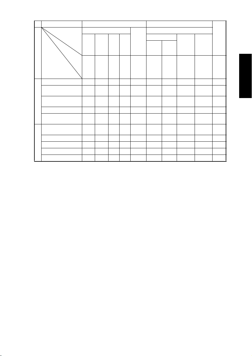
Job Type Machine Adjust 2 Machine Adjust 1 Grada-
Job item IR Area Org.
Left
Top
Image
Refer-
ence
position 10
±1 mm
CD-
Mag.
200
±1
mm
Image
Section
Parts List
CCD Assy replacement 2 1 3 4 ––– – –5
Mirror/lens/Original
Glass cleaning
Exposur e Lamp
IR
replacement
Cable coming unwound 2 1 3 4 ––– – –5
Original Size Detecting
Sensor replacement
PH Upper/Lower Assy
replacement
Window 1 cleaning ––––– – – – – 1
PH
Window 2 cleaning ––––– – – – – 1
Window 3 cleaning ––––– – – – – 1
Window 4 cleaning ––––– – – – – 1
Check
Lead-
ing
edge
0 ±1
mm
––––– – – – – 1
––––– – – – – 1
––––1 –– – – –
6578– 34 1 2 9
FD-
Mag.
300
±1.5
mm
Detect
Sensor
Check
OK after
adjust-
ment.
Top Margin Left Mar-
Image
Start
Position
5 ±0.25 mm0 ±0.5 mmVoid
auto
Lead
Edge
Position
PRT Area
image on
left/right:
3 ±1.5
gin
mm
Dup. Left
Margin
Void
image on
left/right:
3 ±1.5
mm
tion
Adjust
Run
three
times.
D-97
Page 5
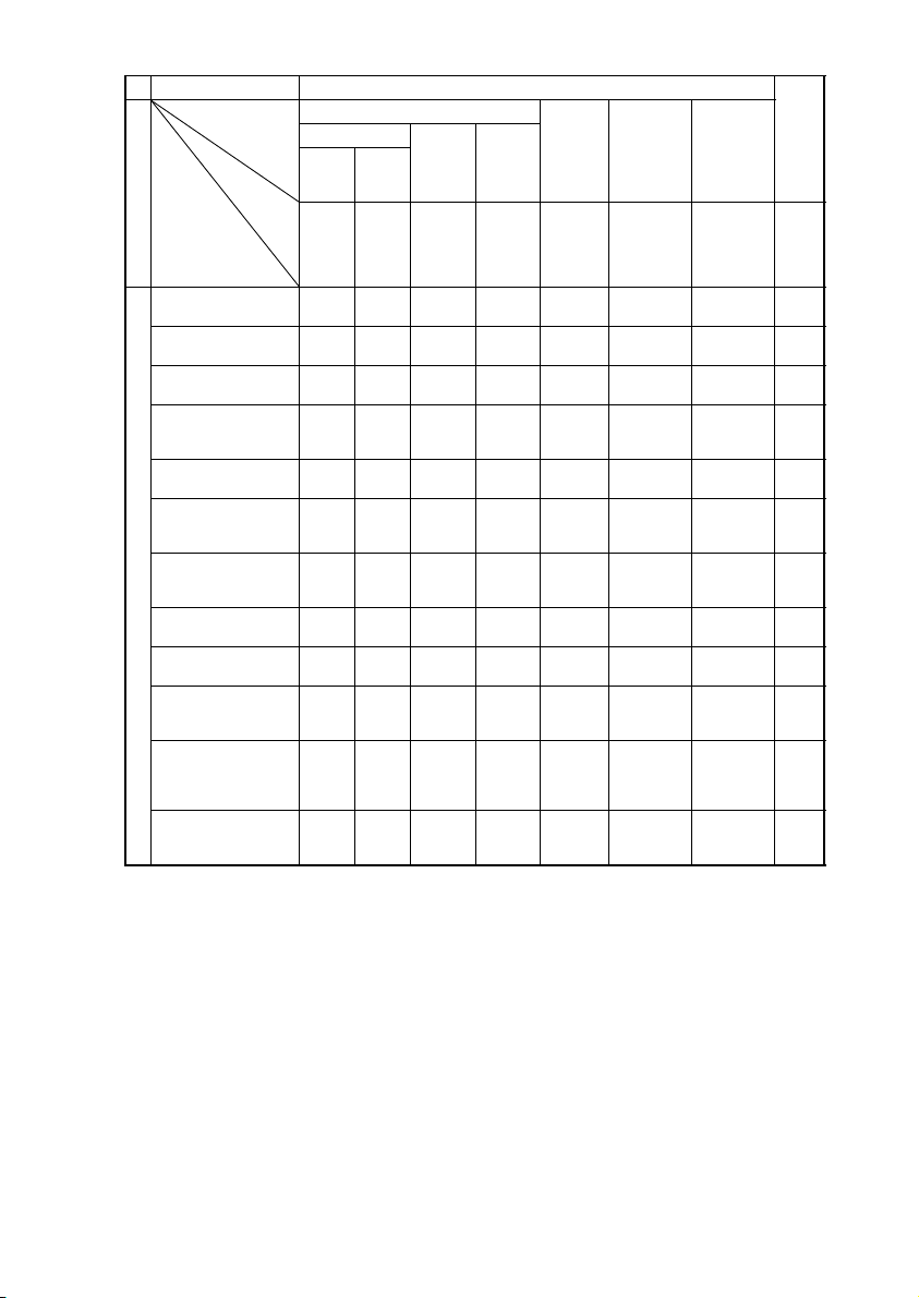
Job Type Machine Adjust 1 Grada-
Job item PRT Area Jam Sen-
Section
Parts List
Transfer Unit replacement
Transfer Film replacement
Image Transfer Corona
unit replacement
Image Transfer Corona
wire cleaning/replacement
Image Transfer Corona
housing cleaning
Paper Bonding Failure
Detection Board 1 sensor cleaning
Paper Bonding Failure
Detection Board 2 sensor cleaning
Transfer
Sensor Adj. Board
replacement
High Voltage Unit 3
replacement
Pre-Image Transfer
Corona Assy replacement
Pre-Image Transfer
Corona Comb Electrode/grid cleaning/
replacement
Pre-Image Transfer
Corona housing cleaning
Top Margin Left Mar-
Image
Start
Position
Check
5 ±0.25 mm0 ±0.5 mmVoid
45 2 3 1 ––6
45 2 3 1 ––6
–– – – – – – 1
–– – – – – – 1
–– – – – – – 1
–– – – 1 –––
–– – – 1 –––
–– – – 1 –––
–– – – – 1 ––
–– – – – – – 1
–– – – – – – 1
–– – – – – – 1
Lead
Edge
Position
gin
image on
left/right:
3 ±1.5
mm
Dup. Left
Margin
Void
image on
left/right:
3 ±1.5
mm
adjust-
Point at
which
LED1 and
2 go out.
sor
ment
Transfer
Output
adjustment
Transfer out-
put should
not be more
or less than
required.
Feed Motor
Speed
adjustment
Color image
registration
deviation
within 0.5
dots
tion
Adjust
Run
three
times.
D-98
Page 6

Job Type Machine Adjust 1 Grada-
Job item Transfer Out-
put adjustment
Check
Section
Parts List
Paper Take-Up/Feed Roll Assy
cleaning/replacement
Paper Separator Roll cleaning/
replacement
Synchronizing Roller cleaning – 1 –––
Transport Roller cleaning – 1 –––
Paper take-up
Vertical Transport Roller cleaning – 1 –––
Copy paper not recommended 2 1 ––3
Fusing Unit replacement ––21–
Fusing Roller (Upper/Lower)
replacement
Fusing Roller bushing (upper/
lower) replacement
Fusing Unit
Coil Collecting Blade cleaning/
replacement
Transfer output
should not be
more or less
than required.
– 1 –––
– 1 –––
––21–
––21–
––21–
Feed Motor
Speed adjust-
ment
Color image
registration
deviation within
100 µm
Fuser Speed
adjustmen t
Magenta image
should not be
brushed or
blurred.
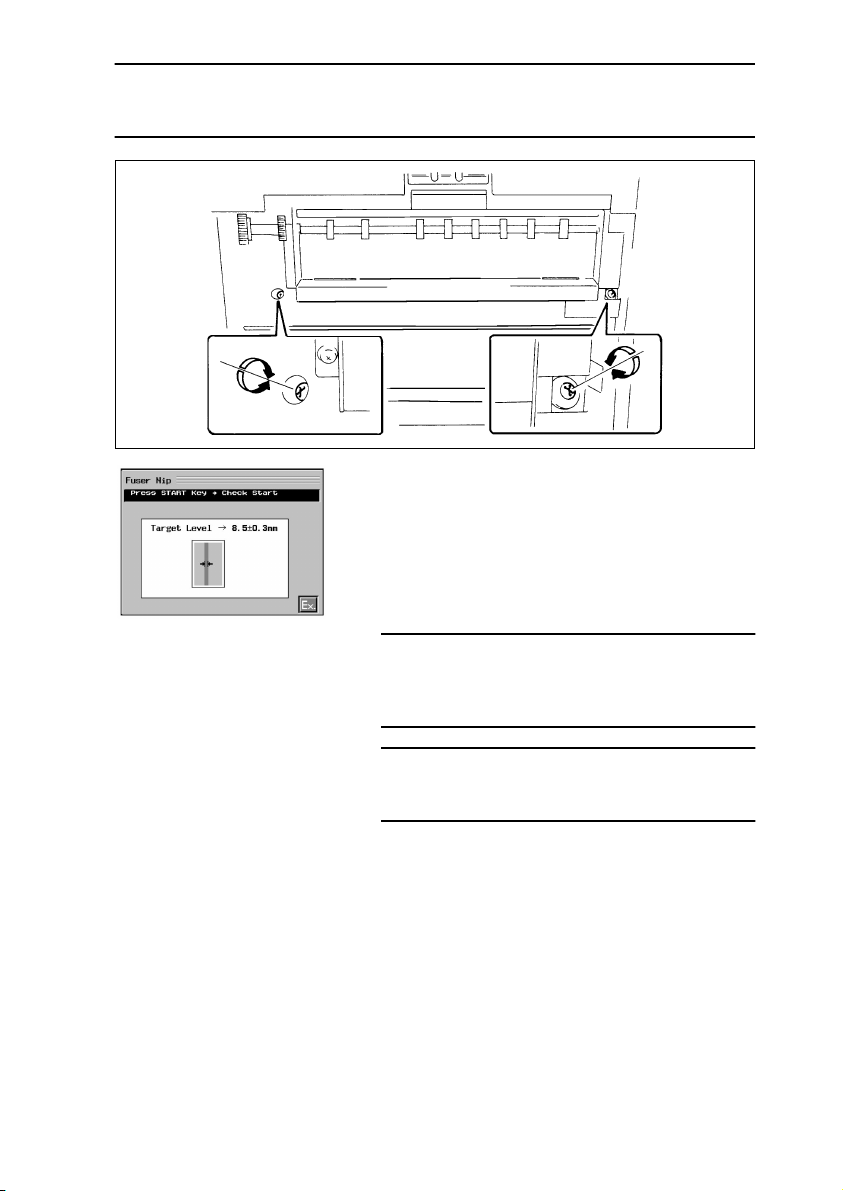
Fuser Nip
adjustment
8.5 ±0.3 mm at
center; right-
left difference
0.5 mm
tion
Adjust
Run three
times.
D-99
Page 7
Job Type Developer Change
Job item Developer
Check
Section
Parts List
Paper Take-Up Motor replacement
Fusing Motor replacement –– – – – –
PC Drum Drive Motor replacement
Control
RAM Pack replacement
Use jig. Use jig. Reference
Bk Developing Unit
Developer
Filling
Discharge
–– – – – –
–– – – – –
2
Bk Developing Unit
only
only
1
AIDC Sensor adjust-
voltage 4.0
±0.3V
AIDC Sen-
ment
sor offset
level adjust-
Auto adjust-
456 3
ATDC Sen-
sor adjust-
ment
5.0 ±0.2% After auto
ment
ment
Bk unit-to-unit
variations
adjustment
adjustment,
check correc-
tion valu e.
Job Type
Section
Parts List
Paper Take-Up Motor replacement
Fusing Motor replacement ––(1) ––
PC Drum Drive Motor replace-
Control
ment
RAM Pack replacement 7 ––––
✽
(1) Check.
Machine Adjust
2
Job item Org. Detect
Sensor adjust-
ment
Check
Check OK after
auto adjust-
ment.
– (1) –––
––(1) ––
Feed Motor
Speed adjust-
ment
Color image
registration
deviation within
100 µm
Machine Adjust 1
Fuser Speed
adjustment
Magenta image
should not be
brushed or
blurred.
Fuser Nip
adjustment
8.5 ±0.3 m m at
center; right-left
difference 0.5
mm
Gradation
Adjust
Run three
times.
D-100
Page 8
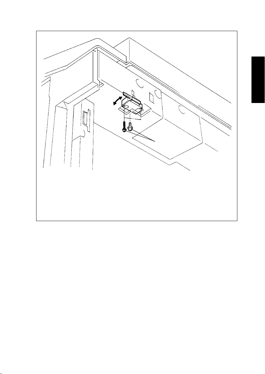
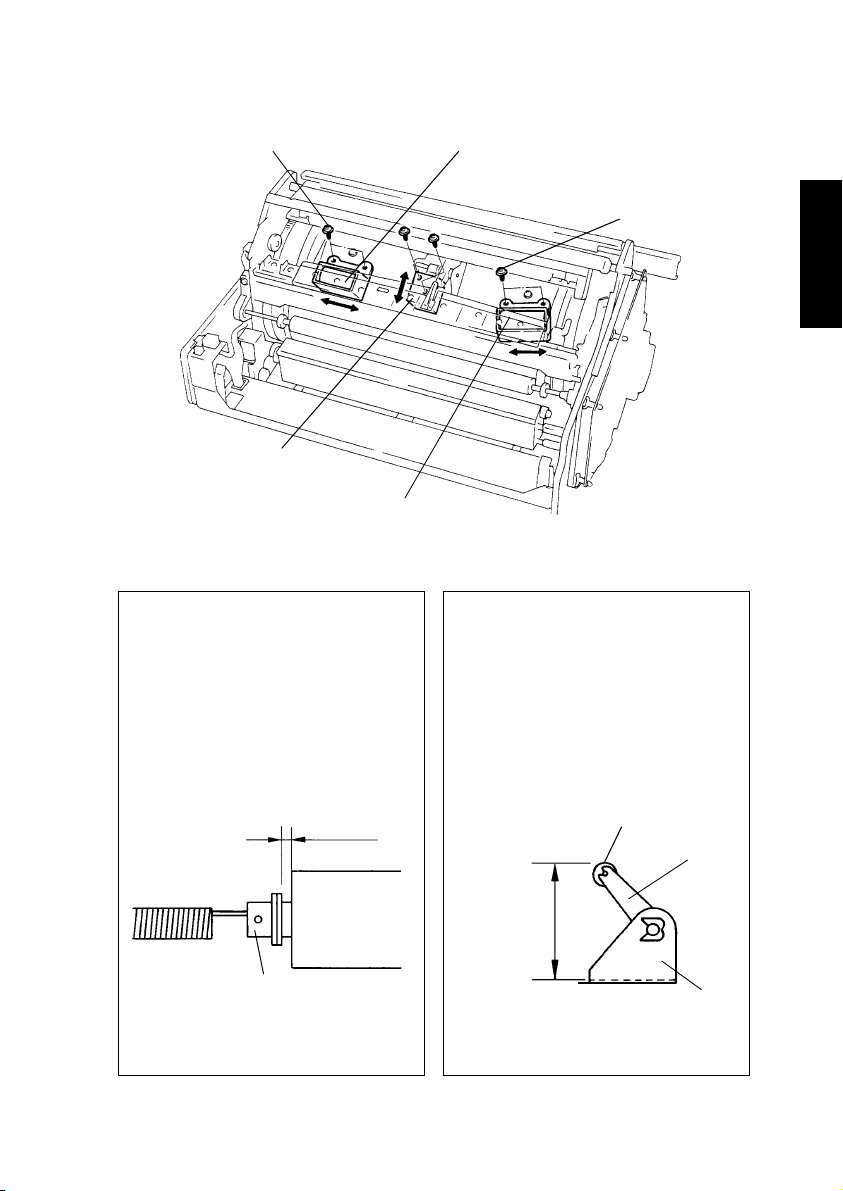
3-3. ADJUSTMENT OF SWITCHES
Adjusting screws
1179D071AA
1. Open the Front Door.
Loosen the Front Door Interlock Switch assy adjusting screws.
2. If the Front Door Interlock Switch is in the deactuated position when the Front Door is
closed, move the Front Door Interlock Switch assy to the front.
If the Front Door Interlock Switch remains actuated because it is located too far forward, move the Front Door Interlock Switch assy towards the rear.
D-101
Page 9
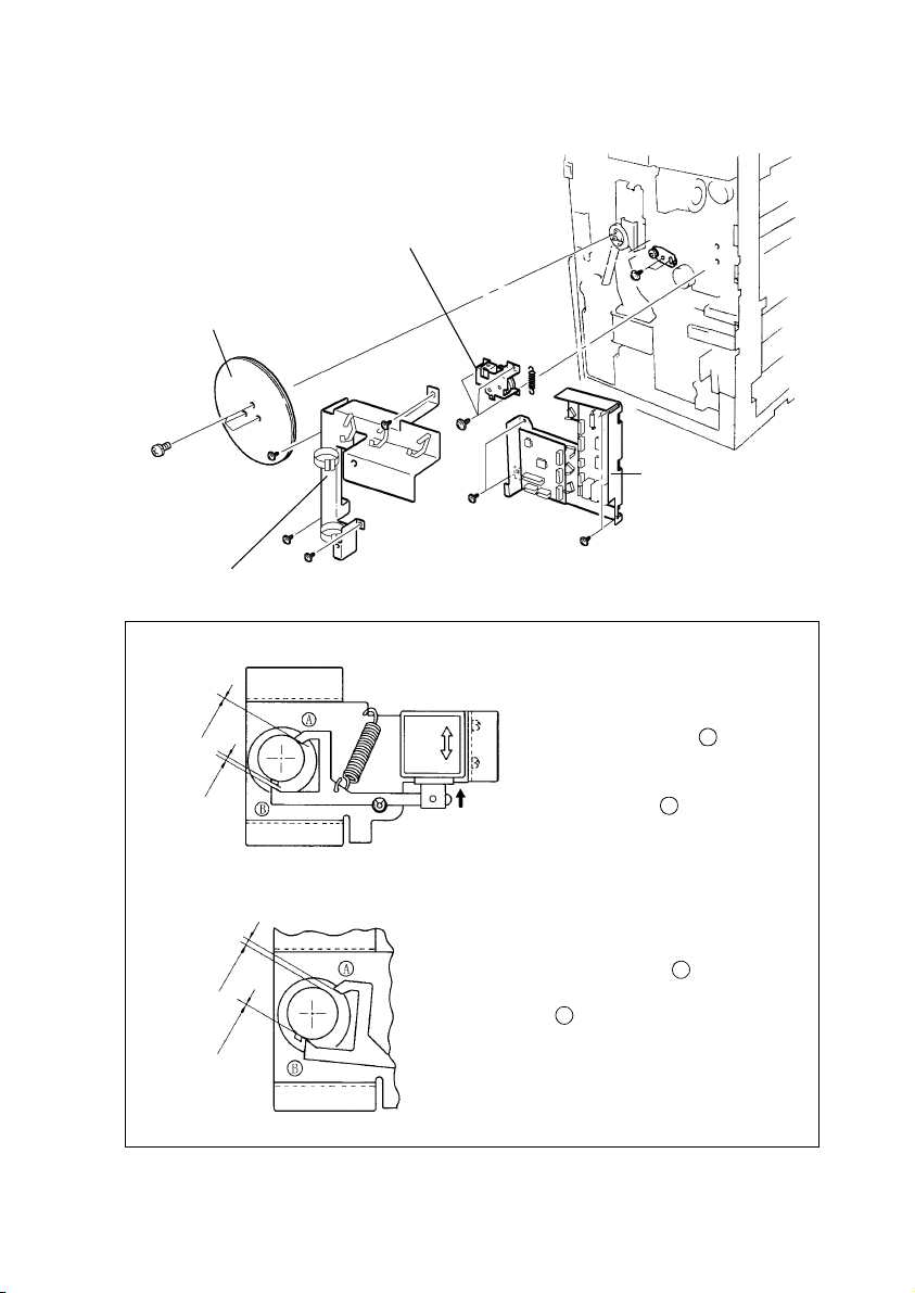
3-4. ADJUSTMENT OF SOLENOIDS
(1) Adjustment of the Transfer Drum Retract Solenoid
4. Transfer Drum
Retract Assy
Fig. 1
1. Flywheel
3. Cover
Fig. 1 Transfer Drum Retract Solenoid Adjusting Procedure
1. Loosen the adjusting screw.
0 mm
2 ±1 mm
2. Manually move the solenoid into
the energized position. The clear-
ance between pawl and ratchet
should be 2 ±1 mm.
At this time, allowing “0” clearance
between pawl and ratchet,
secure the solenoid.
2. Paper Take-Up
Board/Engine
Power Supply
Board Assy
1154D262AD
B
A
1 mm or more
0 mm
1144D196AA
1144D195AA
3. With the solenoid in the deenergized position,
turn the ratchet.
4. The clearance between pawl and ratchet
should be 1 mm or more when the clearance
between pawl and ratchet is “0” (the solenoid
is in the deenergized position).
B
A
D-102
Page 10

(2) Adjustment of the Static Charge Roller Solenoid
1. Transfer Unit cover
Static Charge
Roller Solenoid
Fig. 1
2. Synchronizing/Static
Charge Roller Assy
Fig. 1 Static Charge Roller Solenoid Adjusting Procedure
1144D197AA
Static Charge Roller Solenoid
Adjusting screw
1. Loosen the adjusting screw.
Solenoid energized
Ratchet flat
portion
Solenoid
2. Manually move the solenoid into
3. Secure the solenoid where the
4. Deenergized the solenoid and
Ratchet
Pawl
1144D198AA
tooth
1179D058AA
the energized position.
pawl engages halfway or more
with a tooth, but is not in contact
with the flat portion of the
ratchet.
ensure that the tip of the pawl
does not contact the ratchet
tooth.
D-103
Page 11
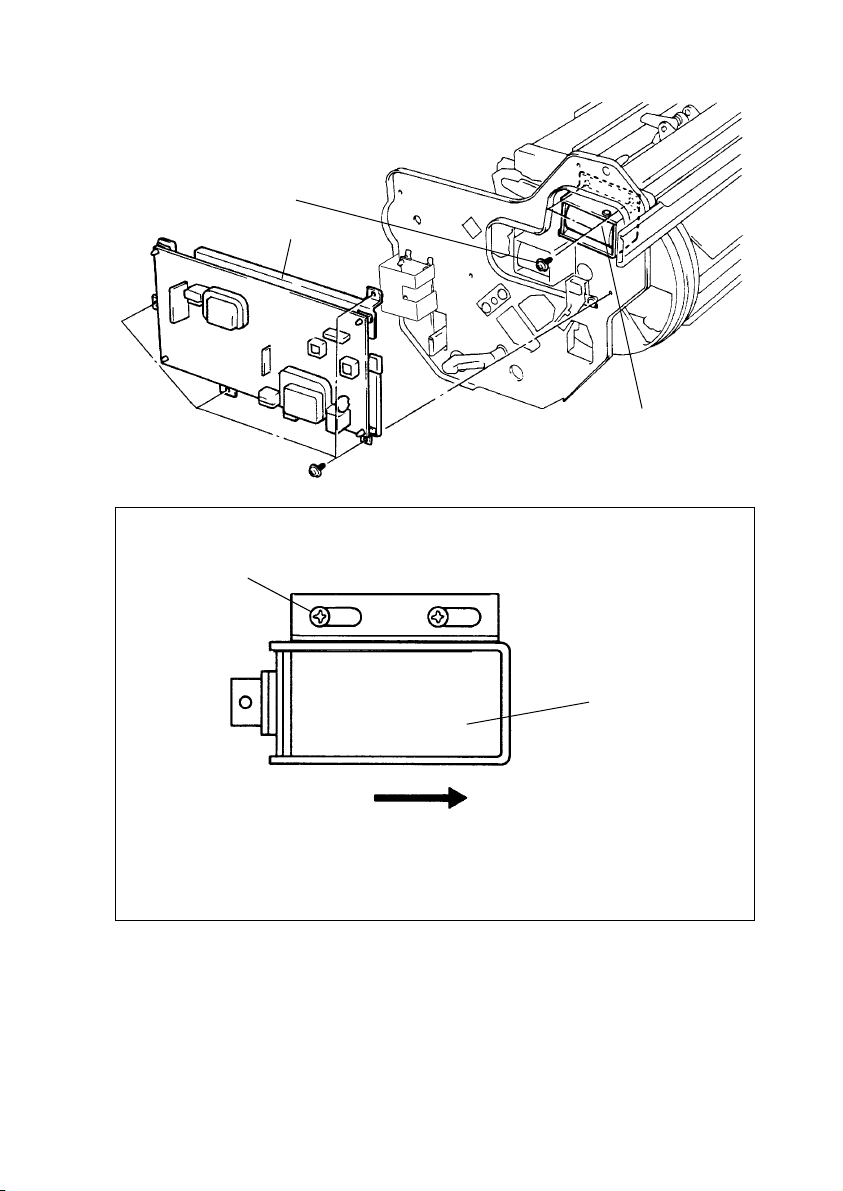
(3) Adjustment of the Paper Separator Finger Solenoid
Adjusting screw
High Voltage Unit 2 Assy
Fig. 1 Paper Separator Finger Solenoid Mounting Position
Screw position
Paper Separator
Finger Solenoid
Fig. 1
1154D259AA
1154D260AA
Slide the solenoid as far as it will go in the slot in the
direction of the arrow before tightening the screws.
D-104
Paper Separator
Finger Solenoid
Page 12
(4) Adjustment of the Internal Fur Brush Solenoid, Backup Brush Solenoid, and
Lifting Finger Solenoid
Adjusting screw
Lifting Finger Solenoid
Fig. 2
Internal Fur Brush Solenoid
Fig. 1
Fig. 1 Internal Fur Brush Solenoid/
Backup Brush Solenoid Adjusting Procedure
1. Loosen the adjusting screw of the
solenoid.
2. Adjust to obtain a clearance of 1 ±0.5
mm for the gap shown below when
the solenoid is manually moved into
the energized position.
1 ±0.5 mm
Backup Brush Solenoid
Fig. 1
Adjusting screw
1154D257AA
Fig. 2 Lifting Finger Solenoid Adjusting
Procedure
1. Loosen the adjusting screw of the
solenoid.
2. Adjust to obtain a lift of 57 ±0.5 mm
from the joint face for the Lifting Finger when the solenoid is manually
moved into the energized position.
Lifting Finger
Arm
Manually move solenoid
into energized position.
1144D201AA
Check for correct clearance when
the spring is not stretched.
Amount of lift
57 ±0.5 mm
Mounting
bracket
1154D258AA
D-105
Page 13
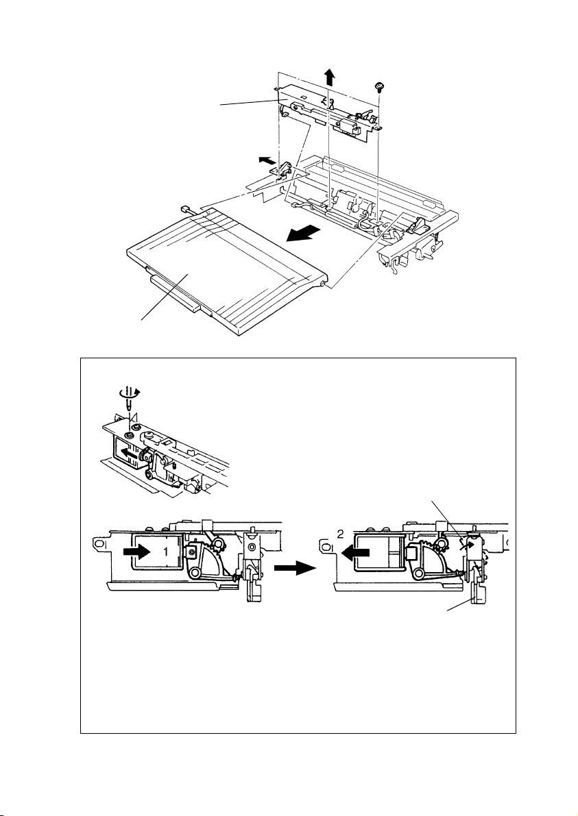
(5) Adjustment of the Manual Feed Paper Pick-Up Solenoid
Manual Feed Paper PickUp Solenoid assy
Fig. 1
Multi Bypass Table assy
1179D018AA
Fig. 1 Manual Feed Paper Pick-Up Solenoid Adjusting Procedure
1. Manually move the solenoid into the energized
position.
2. Loosen the adjusting screws.
Lock lever
1075D155AA
1075D156AB
Paper Stopper
1075D157AB
3. Move the solenoid in the direction of arrow 1 and then move it slowly in the direction
of arrow 2.
4. Move the solenoid to a position at which the Paper Stopper lock levers are in the
upright position (at which the Paper Stoppers are locked).
If the solenoid is moved too far, it will be released from the SET position. If it is
released from the SET position, energize the solenoid and start the procedure over.
5. Tighten the two screws that secure the solenoid in position.
D-106
Page 14
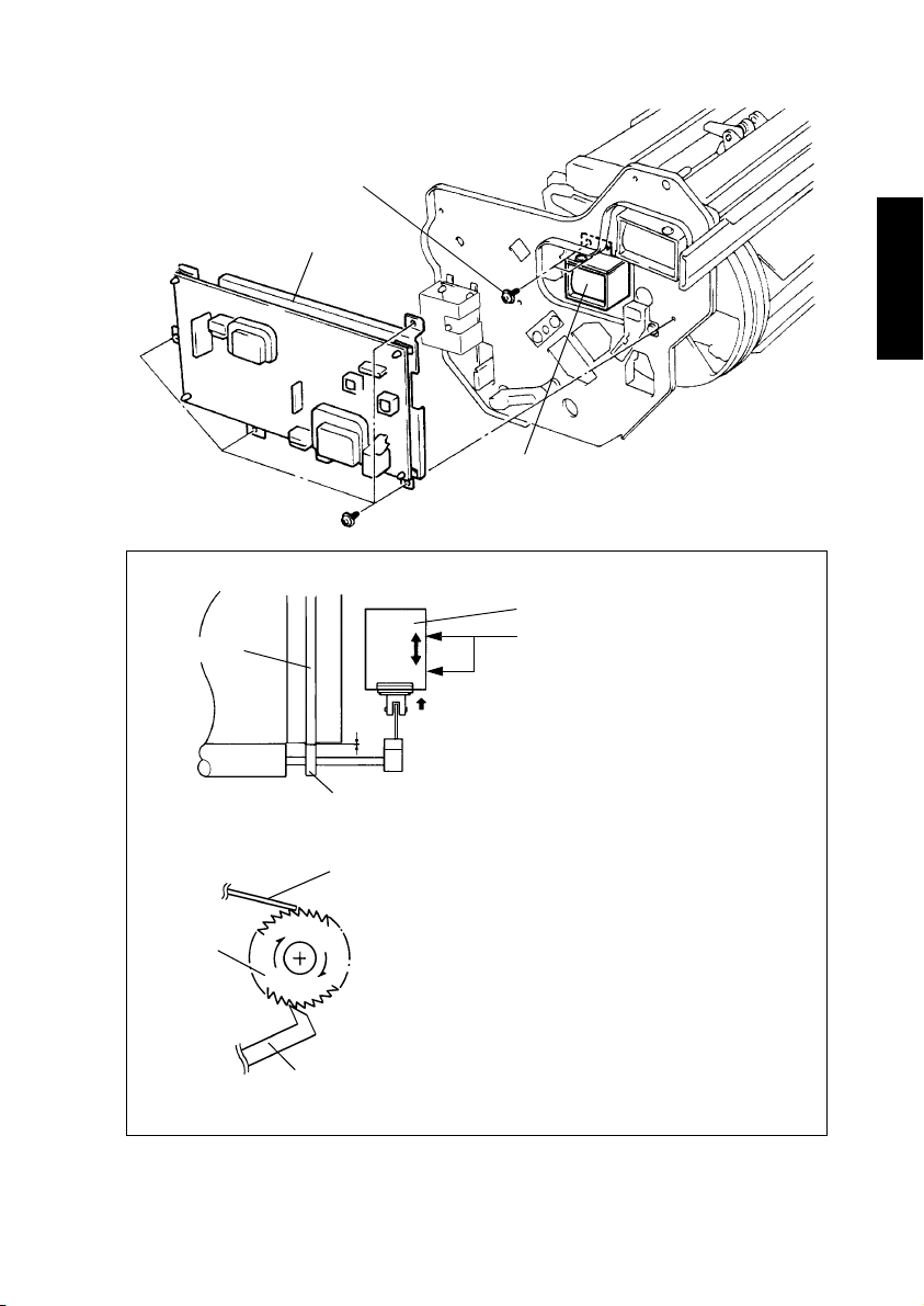
(6) Adjustment of the Oil Roller Solenoid
Adjusting screw
High Voltage Unit 2 assy
Fig. 1 Oil Roller Solenoid Adjusting Procedure
Rubber Ring
Oil Roller Solenoid
Fig. 1
1154D255AA
Oil Roller Solenoid
1. Loosen the adjusting screws.
Oil Collecting Roller
Ratchet
Lever
1154D256AA
0
Roll
Flat spring
1144D207AA
2. Manually move the solenoid into the
energized position and, where the
clearance between the rubber ring of
the Transfer Drum and the front and
rear roll of the Oil Collecting Roller
becomes “0,” secure the solenoid in
position.
3. When the solenoid is manually energized and deenergized, it should click
twice or more.
D-107
Page 15
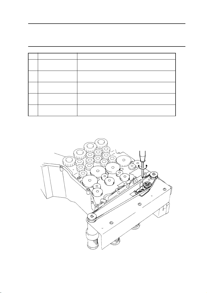
3-5. ADJUSTMENT OF BELT TENSION
Tip
A given tension is being applied to the torsion spring or tension spring fitted to the tension
plate that keeps each timing belt taut. Simply loosening and tightening the mounting
screw(s) therefore allows belt tension to be adjusted.
No. Driven Mechanism Adjusting Procedure
1 Developing Unit
2 Hopper
3 Paper Take-Up
4 Cleaning Unit
5 Scanner Drive
(Example) Adjustment of Hopper Unit Timing Belt
Loosen the two tension plate mounting screws and then tighten them again.
Loosen one tension plate mounting screw and then
tighten it again.
Loosen two tension plate mounting screws and then
tighten them again.
Loosen one tension plate mounting screw and then
tighten it again.
Loosen two tension plate mounting screws and then
tighten them again.
Loosen three Scanner Motor assy mounting screws
and then tighten them again.
D-108
1154D210AB
Page 16
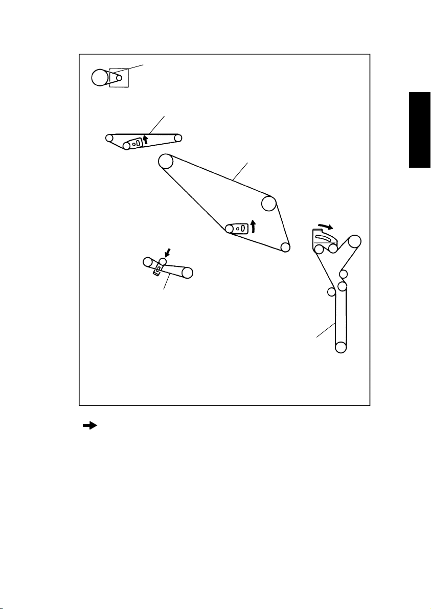
Timing Belt Locations (Viewing Copier from the Back)
5
2
1
4
Tensioning Direction
3
1179D059AA
D-109
Page 17
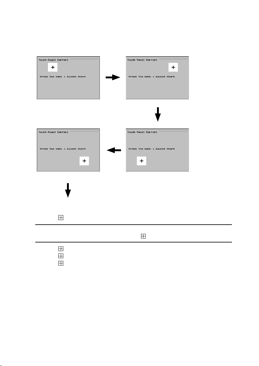
3-6. TOUCH PANEL CORRECTION MODE
1. Press the following keys in this order to set the copier into the Touch Panel Correct
mode: Stop → 0 → Stop → 3.
12
1144S009CA
1144S010CA
43
1144S012CA
1144S011CA
Basic Screen
2. Touch on screen 1.
NOTE
At this time, be sure to touch the exact center of . (The same is true with the following.)
3. Touch on screen 2.
4. Touch on screen 3.
5. Touch on screen 4.
D-110
Page 18
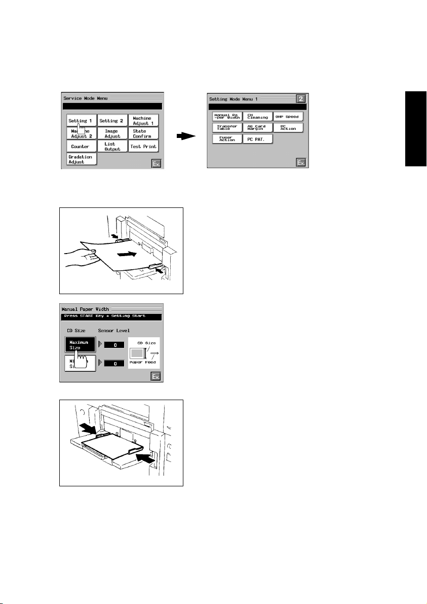
3-7. SETTING MODE
1. Press the Utility key and then select “Meter Count” to open the Meter Count screen.
2. Press the following keys in this order to show the Service Mode Menu screen: Stop → 0
→
0 → Stop → 0 → 1.
3. Select “Setting 1.”
1179P439CA
(1) Manual Paper Width
1144D268AA
1154D075CA
1179P440CA
1. Place several sheets of A3 wide (305 mm × 457
mm) or 12 × 18 paper on the Multi Bypass Table.
2. Select “Manual Paper Width.”
3. Select “Maximum Size” and press the Start key.
(This will start an automatic adjustment
sequence.)
4. Remove the A3 wide (305 mm × 457 mm) or 12 ×
18 paper from the Multi Bypass Table and,
instead, place several sheets of B5 lengthwise or
5-1/2 × 8-1/2 paper on the table.
1144O013YA
D-111
Page 19
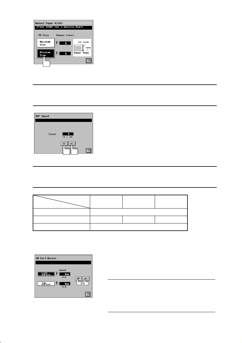
5. Select “Minimum Size” and press the Start key.
(This will start an automatic adjustment
sequence.)
6. After the adjustments have been made, touch
“Ex.”
1154D076CA
(2) OHP Speed
Adjustment
• If lines appear in the CD direction (paper separation failure), increase the setting value.
• If OHP transparency is low, decrease the setting value.
1. Select “OHP Speed.”
2. Change the setting value using the shift keys.
3. After the adjustments have been made, touch
“Ex.”
1154D108CA
NOTE
Whenever a change is made in the Fuser Temp. setting under Machine Adjust 1, OHP
Speed is automatically adjusted so that the OHP fusing efficiency does not change.
Paper
Fuser Temp.
155 °C 160 °C 165 °C
Standard Paper 168 mm/s
OHP 80 mm/s 90 mm/s 100 mm/s
Heavy Stock 2 70 mm/s
(3) A6 Card Margin (4 × 6 Paper Margin)
Given in ( ) is the function name for the inch areas.
1. Select “A6 Card Margin” or “4 × 6 Paper Margin.”
2. Change the setting value using the shift keys.
3. After the adjustments have been made, touch
“Ex.”
Setting Range
Left Margin (void image width on right and left
edges): 3 to 5 mm
1179P441CA
Top Margin (void image width on leading edge): 5 to
8 mm
D-112
Page 20

3-8. MACHINE ADJUST MODE
1. Press the Utility key and then select “Meter Count” to open the Meter Count screen.
2. Press the following keys in this order to show the Service Mode Menu screen: Stop → 0
→
0 → Stop → 0 → 1.
3. Select “Machine Adjust 1” or “Machine Adjust 2.”
Machine
Adjust 1
1179P443CA
1179P442CA
Machine
Adjust 2
(1) Fuser Nip
NOTE
After Fuser Nip has been adjusted, Fuser Speed must also be adjusted.
1. Load any one of the drawers or the Multi Bypass
Table with A4 crosswise or 8-1/2 × 11 crosswise
paper.
2. Open the Front Door and slide out the Transfer
Unit.
3. From the position where the Fusing Roller pressure adjusting screws are fully tightened, back
1144U017AA
them off four turns, while ensuring uniform pressure on the front and rear ends.
4. Slide the Transfer Unit back into the copier.
5. Close the Front Door.
1179P444CA
D-113
Page 21
Reference
The Fusing Roller pressure adjusting screws can be adjusted by removing the Middle Left
Cover.
1144D254AA
6. Select “Fuser Nip” from the “Machine Adjust 1”
menu.
7. Press the Start key.
8. Measure the nip width at the front and rear ends
of the copy fed out onto the Exit Tray.
9. If the measurement falls outside the specified
range, turn the Fusing Roller pressure adjusting
1179P445CA
screws as necessary.
Specifications
Nip width: 8.5 ±0.3 mm
Difference in nip width between front and rear: Within
0.5 mm
Adjustments
8.8 mm <: Loosen the adjusting screw.
8.2 mm >: Tighten the adjusting screw.
10. After the adjustments have been made, touch
“Ex.”
D-114
Page 22
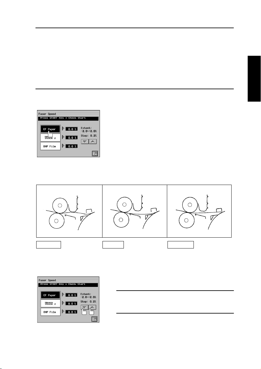
(2) Fuser Speed
NOTES
1. This adjustment should be made after Fuser Nip has been adjusted.
2. A specific paper source and type of paper must be used for each type of paper available
on the Touch Panel as follows.
• CF Paper: Load any of the drawers with A3 or 11 × 17 paper.
• Heavy Stock 2: Load the Multi Bypass Table with A3 or 11 × 17 paper weighing 129 to
2
209 g/m
.
• OHP Film: Load the Multi Bypass Table with A4 lengthwise or 8-1/2 × 11 lengthwise
paper.
3. Open the Front Door and remove the Transfer Unit cover.
4. Install the Interlock Switch Actuating Jig.
5. Select “Fuser Speed” and then “CF Paper.”
1179P446CA
6. Press the Start key and check to see if an adequate length of loop is formed before the
Fusing Rollers.
1154D215AA 1154D212AA 1154D213AA
Retarded Correct Advanced
The loop length is too long
causing the paper to have
too much slack.
A good length of loop is
formed as the paper moves
into the Fusing Rollers.
No loop is formed causing
the paper to be taut.
7. If the timing is advanced or retarded, change the
setting of Fuser Speed.
Adjustments
Retarded: Increase the setting.
Advanced: Decrease the setting.
8. Check the length of the loop again and repeat the
1179P447CA
above steps until a good length of loop is
obtained.
D-115
Page 23
1179P448CA
1179P449CA
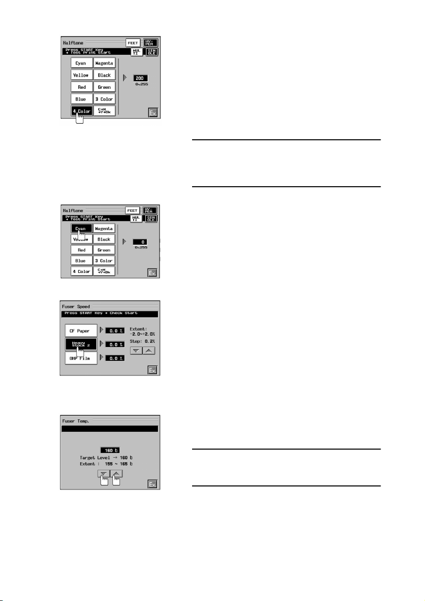
9. Touch “Ex.” Twice to go back to the Service Mode
Menu screen. Then, touch “Test Print” and then
“Halftone” → “4 Color.”
10. Press the Clear key and enter “200” for TD (Test
Data). Then, check the length of the loop before
the Fusing Rollers and check the test print for
“brush effect.”
11. If the loop length is long and “brush effect” is evident on the test print, increase the setting until
“brush effect” disappears.
NOTE
If no “brush effect” is evident on the test print, no
adjustments are necessary and steps 10 and 11 may
be omitted.
12. Select “Cyan” for Test Print/Halftone.
13. Press the Clear key, enter “0” for TD (Test Data),
and check the loop length before the Fusing Rollers.
14. Make the necessary adjustments for Heavy Stock
2 and OHP Film by following steps 4 through 6.
15. After the adjustments have been made, touch
“Ex.”
(3) Fuser Temp.
1179P450CA
1. Select “Fuser Temp.” from the “Machine Adjust 1”
menu.
2. Change the setting value using the shift keys.
Setting Range: 155 to 165 °C
Initial Setting: 160 °C
Step: 5 °C
1179P451CA
D-116
Page 24
(4) AIDC Offset
NOTES
• This adjustment should not be made individually.
• It must be made as part of a series of operations run in Developer Change Mode.
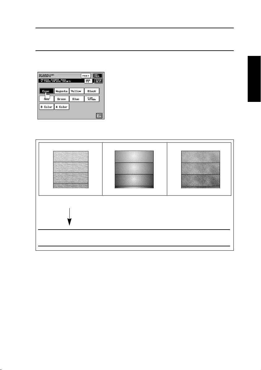
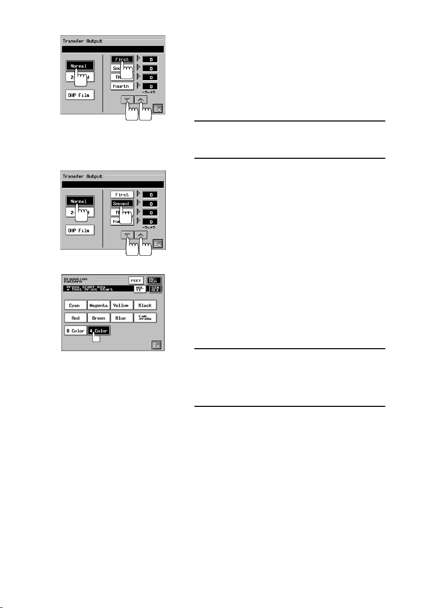
(5) Transfer Output
1. Load a drawer with A3 or 11 × 17 paper.
2. From the Service Mode Menu, select “Test Print.”
Then, select “Gradation Pattern” → “Cyan.” Now,
press the Start key.
1179P452CA
3. Check the test print produced for the following.
<Low T/C> <Poor Image Transfer>
1144D244AA1144D242AA
<Excessive Image Transfer>
1144D243AA
<Low T/C> <Poor Image Transfer> <Excessive Image Transfer>
Entire image has a lightly
brushed effect with uneven,
irregular low image density.
Even, high image density
at the edges with lower
density inside.
If the entire image has a heavily brushed effect, select “Copying Status” from “State
Confirm” and press the Start key to check for T/C of each color of toner.
D-117
Page 25
1154D086CA
1154D087CA
4. For Poor Image Transfer or Excessive Image
Transfer, touch “Ex.” twice to return to the Service
Mode Menu screen.
5. Select “Machine Adjust 1” and then “Transfer Output.”
6. Select “Normal” and “First” (image transfer number), in that order, and change the setting as necessary using the shift keys.
Adjustments
Excessive Image Transfer: Decrease the setting.
Poor Image Transfer: Increase the setting.
7. Select again “Test Print” → “Gradation Pattern” →
“Cyan” and then press the Start key.
8. Check the test print produced.
9. After the adjustment has been made, select
“Transfer Output” again and, using the shift keys,
set the same value as that for “First” of “Normal”
for “Second,” “Third,” and “Fourth.”
10. Select “Test Print” → “Gradation Pattern” → “4
Color” and then press the Start key.
11. Make the final check on the test print produced.
12. If Poor Image Transfer or Excessive Image Transfer is evident on magenta, yellow, or black on the
test print, make an independent setting for Second, Third, or Fourth.
1179P453CA
Transfer Output Order (Transfer Number)
First: Cyan
Second: Magenta
Third: Yellow
Fourth: Black
13. Using these procedures, make adjustments for
“2-Sided” and “OHP Film.”
14. After the adjustments have been made, touch
“Ex.”
D-118
Page 26

(6) Jam Sensor
1. Open the Front Door, remove the Transfer Unit
cover, and then lock the Transfer Unit back into
position.
2. Install the Interlock Switch Actuating Jig.
3. Select “Machine Adjust 1” and “Jam Sensor.”
Then, press the Start key.
1144D284CA
4. After the Transfer Drum has stopped turning, turn RT1 on the Failure Sensor Adj. Board
clockwise until LED1 (red) turns ON and then turn it counterclockwise until LED1 turns
OFF.
LED2
LED1
S1
RT1
RT2
S2
RT1: LED1: S1: For sensor on Paper Bonding Failure Detection Board 2
RT2: LED2: S2: For sensor on Paper Bonding Failure Detection Board 1
5. If LED1 (red) does not light up in step 4:
LD1 LD2
1. Flip DIP switch S1-1 on the Failure Sensor Adj. Board to
the OFF position and then perform step 4 again.
2. If LED1 does not still light up, flip DIP switch S1-1 to the
ON position again and flip S1-2 to OFF. Then, perform
S1
S1-1
S1-2
RT1
ON
OFF
ON
OFF
S2
S2-1
RT2
S2-2
step 4 again.
3. If LED1 does not still light up, flip S1-1 to OFF and, with
S1-2 in the OFF position, carry out step 4 again.
1179D060AB
For sensor on Paper Bonding Failure Detection Board 1
For sensor on Paper Bonding Failure Detection Board 2
D-119
1179D075AA
Page 27
6. Turn RT2 on the Failure Sensor Adj. Board clockwise until LED2 (green) turns ON and
then turn it counterclockwise until LED2 turns OFF.
7. If LED2 (green) does not light up in step 6, change the DIP switch S2 key positions as
necessary to make an adjustment.
8. After the adjustment has been made, press the Stop key and touch “Ex.”
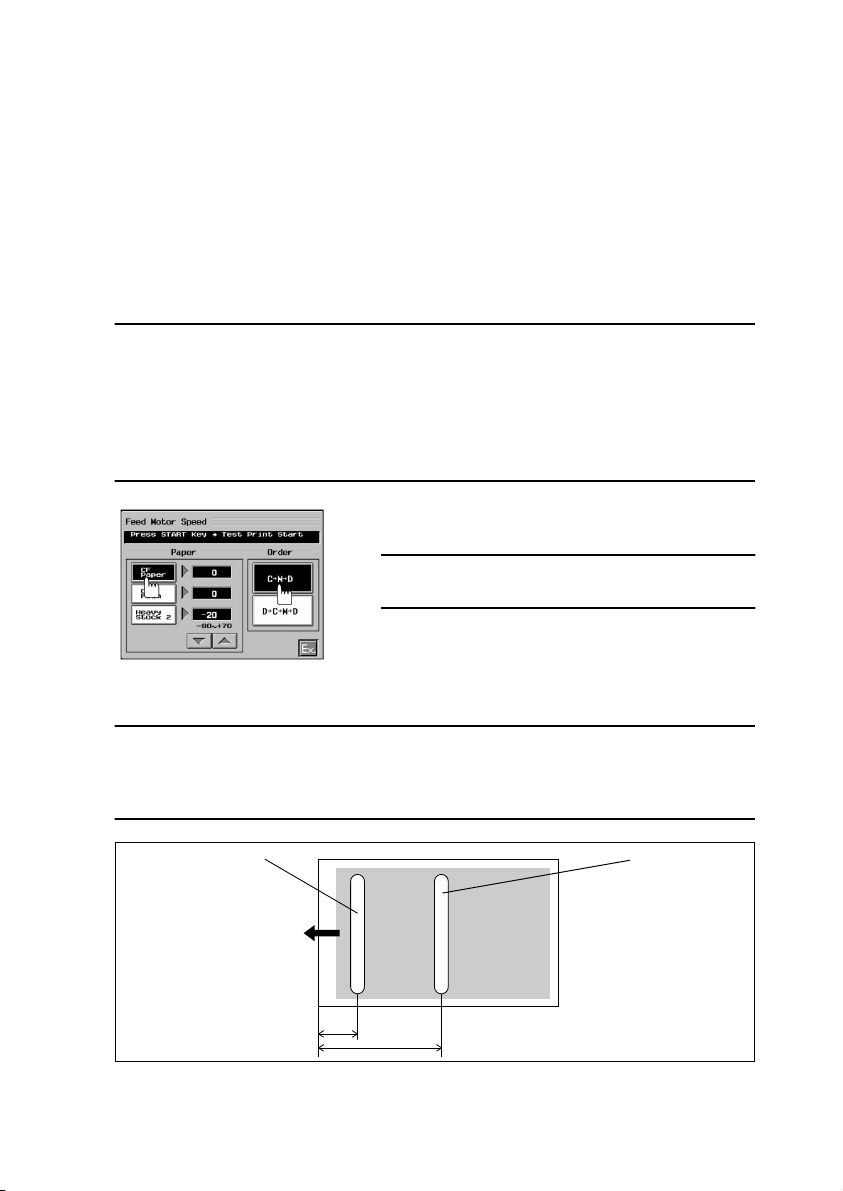
(7) Feed Motor Speed
<Normally>
The amount of color overlay deviation between C and M is uniform throughout the entire
print area.
<When faulty>
The amount of color overlay deviation between C and M varies from one point to another on
the image.
NOTE
A specific paper source and type of paper must be used as detailed below according to the
paper type selection made on the Touch Panel.
• CF Paper: Load the drawer with A3 or 11 × 17 paper.
• OHP Film: Place A4L or 8-1/2 × 11L OHP transparencies on the Multi Bypass Table.
2
• Heavy Stock 2: Place A3 or 11 × 17 paper weighing 129 to 209 g/m
on the Multi Bypass
Table.
1. Select “Feed Motor Speed” of “Machine Adjust
1.” Then, select “CF Paper” and “C → M → D.”
NOTE
Do not select “D → C → M → D.”
2. Press the Start key.
1179P454CA
3. Using a loupe, measure the amount of color overlay deviation of the test copy produced.
Specifications
m max.
100
µ
Tip:
Check especially at the leading edge and at the center.
Leading Edge
Center
Feeding
Direction
50
mm
200 mm
1179D073AB
D-120
Page 28
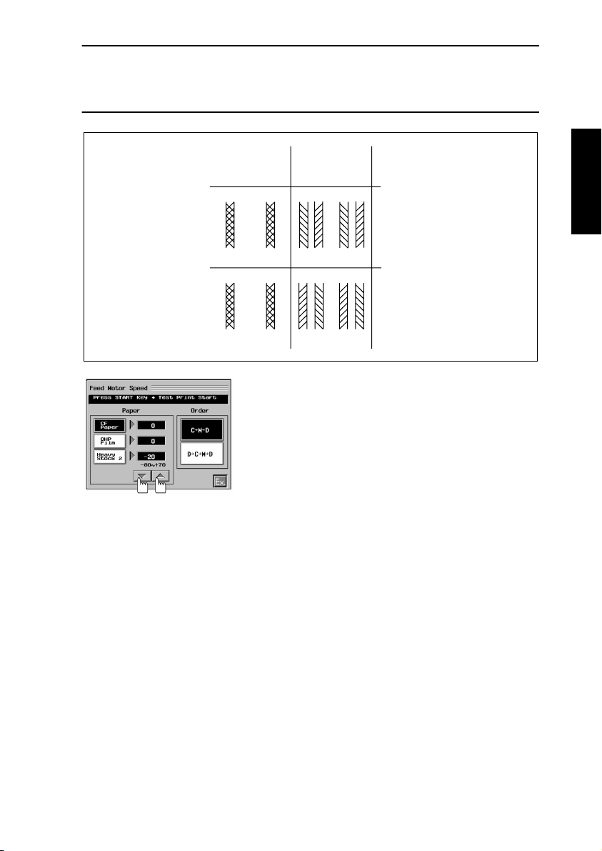
Criteria
Deviation at Center, but not at Leading Edge:
M (magenta) is relatively advanced → Feed Motor speed is faster.
M (magenta) is relatively retarded → Feed Motor speed is slower.
Out-of-Phase Example:
Leading
Edge
Center
C M C M
M C M C
1154D222AA
Criteria
→
Too slow
→
Too fast
4. If the specifications are not met, change the setting using the shift keys.
1179P455CA
5. Make a check again by making another test copy.
6. Using the same procedure, adjust for “OHP Film” and “Heavy Stock 2.”
7. After the adjustments have been made, touch “Ex.”
D-121
Page 29
(8) PRT Area
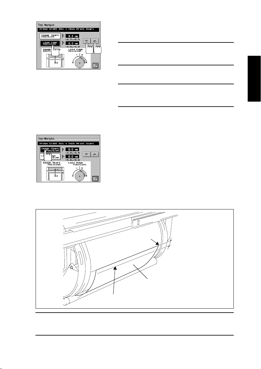
Top Margin
This function permits adjustments of the print start position (Image Start Position) on the
paper which is not affected by the image signal sent from the IR and the point at which the
paper is attracted onto the surface of the Transfer Drum (Lead Edge Position).
NOTES
• This adjustment should be made after Feed Motor Speed has been adjusted.
• Lead Edge Position must be adjusted before Image Start Position.
1. Load the drawer with A3 or 11 × 17 paper.
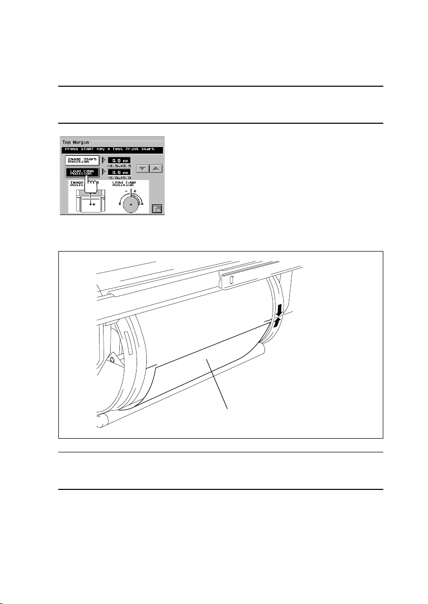
2. Select “PRT Area” of “Machine Adjust 1.”
3. Select “Top Margin” and then “Lead Edge Position.” Then, press the Start key.
4. After a misfeed message has appeared, open the
Front Door.
1154D090CA
5. Slide out the Transfer Drum and measure the distance between the leading edge of the
paper attracted to the drum and the white line on the Transfer Film.
Leading Edge Position
Standard:
0 ±0.5 mm
Paper
1154D199AB
Specifications
Distance between the leading edge of the paper attracted to the Transfer Drum and the
white line on the Transfer Film: 0 ±0.5 mm
D-122
Page 30
6. If the specifications are not met, slide the Transfer
Unit back into the copier and close the Front
Door.
NOTE
At this time, be sure to remove the paper, as the
copier does not perform predrive.
1154D091CA
7. Select “Lead Edge Position” and change the setting using the shift keys.
Adjustments
+0.5 mm <: Increase the setting.
-0.5 mm >: Decrease the setting.
8. After the adjustment has been made, check the
position of the leading edge of the paper
attracted to the Transfer Drum three times.
9. Select “Image Start Position” and press the Start
key.
10. After the misfeed message has appeared, open
the Front Door.
1154D110CA
11. Slide out the Transfer Drum and measure the distance between the leading edge of the
paper attracted to the drum and the white line on the Transfer Film.
White line
5 ±0.25 mm
Paper
Image Start Position Line
1179D077AA
Specifications
Distance between the image start position line on the paper and the white line on the Transfer Film: 5 ±0.25 mm
D-123
Page 31

12. If the specifications are not met, slide the Transfer
Unit back into the copier and close the Front
Door.
NOTE
At this time, be sure to remove the paper, as the
copier does not perform predrive.
1154D111CA
13. Select “Image Start Position” and change the setting using the shift keys.
Adjustments
5.25 mm <: Decrease the setting.
4.75 mm >: Increase the setting.
14. Check the image start position again.
15. After the adjustments have been made, touch
“Ex.”
Left Margin
This function is used after the PH has been replaced or when the reference positions of the
drawer and Multi Bypass Table deviate due to variations in size of paper.
1. Select “PRT Area” of “Machine Adjust 1.”
2. Select “Left Margin” and then “Upper.”
3. Press the Start key.
3 ±1.5mm
1154D093CA
4. Measure the width of the void image on the test
copy as shown on the left.
Specifications:
Void image width: 3 ±1.5 mm
1144D238AA
D-124
Page 32

5. If the measurement falls outside the specified
range, change the setting using the shift keys.
Adjustments
4.5 mm <: Decrease the setting.
1.5 mm >: Increase the setting.
1154D094CA
6. Make a test copy to check again.
7. Using these steps, adjust the remaining drawers
and the Multi Bypass Table (A4C or 8-1/2 × 11C).
8. After the adjustments have been made, touch
“Ex.”
Dup. Left Margin
This function is used after the PH has been replaced or when the reference position of the
Duplex Unit deviates due to variations in size of paper.
1. Select “PRT Area” of “Machine Adjust 1.”
2. Select “Dup. Left Margin” and then “Upper.”
3. Press the Start key.
1154D095CA
4. Measure the width of the void image on the test
copy as shown on the left.
Specifications:
Void image width: 3 ±1.5 mm
3 ±1.5mm
1144D238AA
5. If the measurement falls outside the specified
range, change the setting using the shift keys.
1179P456CA
Adjustments
4.5 mm <: Decrease the setting.
1.5 mm >: Increase the setting.
6. Make a test copy to check again.
7. Using these steps, adjust the remaining drawers.
8. After the adjustments have been made, touch
“Ex.”
D-125
Page 33

(9) A6 Card Passage (4 × 6 Paper Passage)
✽
Shown in ( ) are the display messages for the inch areas.
NOTE
This function is concerned with the adjustment procedure, in which the position of the spur
wheel (sprocket) is checked by examining test copies. The spur wheel (sprocket) position
is, however, rather hard to tell and it is recommended that “Adjustment of Sprocket Unit
Position” contained in “OTHER ADJUSTMENTS” be used.
1. Load thick paper B5L or 5-1/2 × 8-1/2L in the
Multi Bypass Table.
2. Select “A6 Card Passage” of “Machine Adjust 1."
3. Press the Start key to make a test copy.
1179P457CA
4. Determine the position of the spur wheel
Spur Wheel
Position
Feeding Direction
(sprocket) as measured from the edge of the
image on the test copy.
Specifications
A6 Card: 5.5 ±1 mm
4 × 6 Paper: 8 ±1 mm
1179D068AD
5. If the specifications are not met, adjust with the
adjusting screw.
Adjusting
Screw
(10) Paper Loop
1179D067AB
1179P458CA
Adjustments
A6 Card
6.5 mm <: Turn the adjusting screw counterclock-
wise.
4.5 mm >: Turn the adjusting screw clockwise.
4 × 6 Paper
9 mm <: Turn the adjusting screw counterclockwise.
7 mm >: Turn the adjusting screw clockwise.
6. After the adjustments have been made, touch
“Ex.”
1. Select “Paper Loop” of “Machine Adjust 1.”
2. Change the setting using the shift keys.
Setting range: -3 to +3
Initial setting: 0 (target loop length: 8.9 mm)
1 step: 1 (2.4 mm)
D-126
Page 34

(11) IR Area
NOTES
• This function is used to adjust the document scanning position. The check should be
made using a test copy, not a regular copy.
• After this adjustment has been made, be sure to make the IR Lamp adjustment.
• A malfunction of C0660 could result depending on the values set for “Top Image” and
“FD-Mag.”
Left Image and Top Image
1. Load the drawer with A3 paper.
2. Place scales on the Original Glass as shown on
the left and lower the Original Cover.
1144D239AA
3. Select “IR Area” of “Machine Adjust 2.”
4. Press the Start key to make a test copy.
1179P459CA
10 ±1
mm
5. Check the image on the test copy to see where
20
10
5
0~1mm
the graduations of the scales start.
Specifications
Left Image (left edge of the image): 0 ±1 mm
Top Image (leading edge of the image): 10 ±1 mm
1144D240AB
D-127
Page 35

6. If the specifications are not met, select “Left
Image” and change the setting using the shift
keys.
Adjustments
Edge of image +1 mm <: Increase the setting.
Edge of image -1 mm >: Decrease the setting.
1179P460CA
CD-Mag and FD-Mag
1179P459CA
Zoom Ratio
Error
200 190 180
200 190 180
1144D239AA
Scale on
Test Copy
1144D241AA
7. Using the same procedure, adjust “Top Image.”
8. Make a check again by making another test copy.
9. After the adjustments have been made, touch
“Ex.”
1. Load the drawer with A3 or 11 × 17 paper.
2. Place scales on the Original Glass as shown on
the left and lower the Original Cover.
3. Select “IR Area” of “Machine Adjust 2.”
4. Press the Start key to make a test copy.
5. Measure the scale on the test copy.
Specifications
CD zoom ratio: 200 ±1 mm
FD zoom ratio: 300 ±1.5 mm
6. If the specifications are not met, calculate the
zoom ratio error.
Calculation Formula:
Specifications / Measurement Taken on Copy =
Zoom Ratio Correction Factor
D-128
Page 36

7. Select “CD-Mag” and, using the shift keys, input
the correction factor calculated in step 6.
Example:
If the 200-mm position on the copy is 198 mm on the
actual scale, calculate the correction factor as follows:
200 mm
= 1.01
1179P461CA
(12) Orig. Detect Sensor
NOTE:
This adjustment must be made after following:
• Memory clear
• Original size has been incorrectly detected
• An Original Size Detection Sensor has been added or replaced.
198 mm
Using the shift keys, set × 1.01 for the correction factor.
8. Using the same procedure, adjust “FD-Mag.”
9. After the adjustments have been made, touch
“Ex.”
1. Place a blank sheet of A3 or 11 × 17 paper on the
Original Glass and lower the Original Cover.
2. Select “Orig. Detect Sensor” of “Machine Adjust
2.”
3. Press the Start key to run the Orig. Detect Sensor sequence.
1179P462CA
NOTE
During the adjustment sequence, the Start key stays
lit up orange. It turns to a green steady light as soon
as the adjustment is completed.
4. Check that the message “All .. OK” is shown.
Then, touch “Ex.”
D-129
Page 37

3-9. DEVELOPER CHANGE MODE
(1) Developer Change (Developer Discharge
tating)
NOTE
Although functions are available to perform Developer Discharge, Developer Filling, or
Developer Agitating individually, perform “Developer Change” that covers all these in a
given sequence.
1. Turn OFF the Power Switch.
2. Open the Front Door, remove the Toner Antispill Plate, and Toner Hopper Unit.
3. Remove the Developing Unit Cover and slide out the Developing Unit.
4. Install the Jumper Harness and four Mag. Roller Shields.
Jumper Harness
5. Turn ON the Power Switch.
6. Press the following keys in this order to set the
copier into the Developer Change mode: Stop →
0 → Stop → 2.
7. Install the Interlock Switch Actuating Jig.
8. Select “Developer Change.”
→→→→
Developer Filling
Mag. Roller Shield ×4
1179D061AA
→→→→
Developer Agi-
1154D097CA
D-130
Page 38

9. Assemble the Developer Collecting Bag. Using two clips, secure the bag to the Developing Unit (Fig. 1).
10. Remove the ATDC assy from the Developing Unit or Units to be discharged (Fig. 2).
11. Pull the bag up over the front end and clip it with two more clips (Fig. 3).
Fig. 1
Developer Collecting Bag
NOTE
Use care not to damage the lower edge of
the vinyl bag (Developer Collecting Bag)
1144D328AA
when putting the
inner box into it.
Fig. 2 Fig. 3
1154D205AA
Clip ×2
1154D204AA
Clip ×2
1144D323AA
1154D114CA
12. Touch “On” for the color or colors of developer to
be discharged (two or more colors may be
selected).
13. Press the Start key to discharge the developer.
(It takes about 5 min. to discharge all four colors
of developer.)
14. After these steps have been completed, touch
“Ex.” and select “Developer Filling.”
D-131
Page 39

15. Remove the supply port of the Developing Unit which is to be charged with developer
-
and then install the Developer Chute. (In the illustration, the Bk Developing Unit is
selected.)
1154D115CA
1179U017AA
1154D098CA
1144U053AA
1144U054YA
16. Select the color of developer and press the Start
key.
17. Pour in developer through the Developer Chute.
18. When all the developer has been poured in the
Developing Unit, press the Stop key.
Following the same procedure, pour developer of
other colors.
19. After the developer of all colors has been poured,
touch “Ex.”
20. Touch “On” for the color of the developer charged.
(Two or more colors may be selected.)
21. Press the Start key to agitate the developer
selected in step 20.
NOTE
If three or more colors have been selected, the agita
tion sequence takes place twice.
22. The Developing Unit stops automatically when
agitation is completed. Then, touch “Ex.”
23. Turn OFF, then ON, the Power Switch to return to
the initial screen.
D-132
Page 40

(2) After Dev. (C/M/Y/Bk) Has Been Changed
[ATDC Sensor Adjust (Auto) → AIDC Sensor Adjust (Auto) → AIDC Offset → Black ATDC
Adjust]
NOTES
• Although functions are available to perform ATDC Sensor Adjust (Auto), AIDC Sensor
Adjust (Auto), AIDC Offset, or Black ATDC Adjust individually, perform “After Dev. (C/M/Y/
Bk) has been changed” that covers all these in a given sequence.
• If the PC Drum has been replaced at the same time that the developer has been
changed, running this function will complete all the necessary adjustments and there is
no need of running “After PC Drum has been changed.”
1. Open the Front Door.
2. Press the Stop key, 0, Stop key, and 2, in that
order, to set the copier into the Developer
Change mode.
3. Close the Front Door.
4. Select “After Dev. (C/M/Y/Bk) has been changed”
and set the copier into the ATDC Sensor Adjust
1154D099CA
(Auto) mode.
5. Touch “On” for the color to be adjusted and press
the Start key.
1154D100CA
1179P463CA
1154D101CA
6. After the adjustment has been made, the results
are displayed on the Touch Panel. If the results
are acceptable, select “On” to enter the reference
value.
7. After ATDC Sensor Adjust (Auto) has been completed, touch “Ex.” to set the copier into the AIDC
Sensor Adjust (Auto) mode.
8. With the AIDC Sensor Adjust (Auto) screen on
the Touch Panel, press the Start key. This lets
the copier start an automatic adjustment
sequence.
D-133
Page 41

1154D102CA
”
9. After AIDC Sensor Adjust (Auto) has been completed, the results are displayed. If they are okay,
touch “Ex.” to set the copier into the AIDC Offset
mode.
10. With the AIDC Offset screen on the Touch Panel,
press the Start key to let the copier start an automatic adjustment sequence.
11. After the adjustment sequence has been completed, the results are displayed on the Touch
Panel. Make sure that the value shown for each
color falls within the specified range.
1154D102CA
Specifications Range
Cyan, Magenta, Yellow: 60 to 304
Black: 0 to 28
12. If the value is outside the range, return to the Service Mode Menu, select “Test Print”
and “Solid Pattern,” and press the Start key to produce a test print.
13. Check to see if the solid pattern on the test print produced is faulty (particularly if the
image density is too low). If the solid pattern looks good, replace the AIDC Sensor and
make the check again.
14. After AIDC Offset has been completed, touch
“Ex.” to set the copier into the Black ATDC Adjust
mode.
15. With the Black ATDC Adjust screen on the Touch
Panel, press the Start key to let the copier start
the automatic adjustment sequence.
16. After the sequence has been completed, touch
1154D103CA
“Ex.” to return to the Developer Change Mode.
17. Turn OFF, then ON, the Power Switch to return to
the initial screen.
18. Check the Bk Developing Unit for adjustment for
unit-to-unit variations.
Unit-to-Unit Variations Check Procedure
1. Select “State Confirm” from the Service mode
menu.
2. Select “Bk. Toner Sup. Status” and check that the
values for “Dev. Constant” are one other than “0.
1179P464CA
3. After the check, touch “Ex.”
D-134
Page 42

(3) Gradation Adjust
-
Gradation Adjust is to be performed three times to improve correction accuracy after the
copier has been set up and each time a service job has been performed.
1. Press the Utility key and then open the Meter Count screen.
2. Press the following keys in this order to set the copier into the Service mode: Stop → 0
→
0 → Stop → 0 → 1.
3. Select “Gradation Adjust” from the Service Mode Menu.
1144U074AA
1179P465CA
1179P465CA
1179P466CA
4. Press the Start key.
5. Place the test copy fed out of the copier on the
Original Glass.
NOTE
Examine the display on the Touch Panel for the direc
tion in which the copy is to be placed on the glass.
6. Place ten blank sheets of A3 or 11 × 17 paper on
that test copy and lower the Original Cover.
7. Press the Start key again.
✽
The copier scans the original, but does not feed
out a test copy.
8. When the Service Mode Menu reappears on the
Touch Panel, select “Gradation Adjust” again.
9. Press the Start key.
✽
The copier feeds out a test copy at this time.
10. Perform steps 5 through 9 a total of three times.
D-135
Page 43

11. After the copier has completed scanning the original a third time, select “Gradation Adjust” again
and check the values for “Conv. Value.”
Specified Ranges (cyan, magenta, yellow, and
black)
Max.: 0 ±100
1179P466CA
13. If the values fall outside the range, perform “Gradation Adjust” a fourth time and make a
check again.
14. If the values fall within the specified range this time, touch “Ex.”
15. If the values still fall outside the range, make an image sample from the Test Chart and:
• If the sample is not faulty, end the procedure.
• If the sample is faulty, take necessary steps by referring to “IMAGE QUALITY PROB-
LEMS” of TROUBLESHOOTING.
Highlight: 0 ±60
These ranges should be regarded only for reference,
as they are subject to fluctuations with varying environmental conditions.
12. If the values fall within the specified range, touch
“Ex.”
D-136
Page 44

3-10. OTHER ADJUSTMENTS
(1) Adjustment of the AIDC Sensor Position
2. Cover
1. Tape
NOTE
After the sensor has been
adjusted for its correct position,
secure the harness with tape to
prevent it from lifting off.
Fig. 1 Adjusting Procedure
AIDC Sensor
Fig. 1
Developing Unit
1179D062AA
AIDC Sensor Positioning Jig
Adjusting screws
1. Loosen the AIDC Sensor adjusting screws.
2. Install the AIDC Sensor Positioning Jig.
3. Press the AIDC Sensor tightly up against the jig
and, at the same time, tighten the adjusting screws.
D-137
AIDC Sensor
1179D063AA
Page 45

(2) Focus-Positioning of the Scanner and 2nd/3rd Mirrors Carriage
Scanner/Mirrors Carriage
Positioning Jigs
2nd/3rd Mirrors Carriage
Adjusting Procedure
Scanner positioning screw ×2
Scanner
Cable fixing screw
Scanner/Mirrors Carriage Positioning Jigs
Adjusting
screw
1179D219AC
Scanner
2nd/3rd Mirrors Carriage
1144D220AA
1. Loosen the Scanner positioning screws.
2. Install the Scanner/Mirrors Carriage Positioning Jigs.
3. Press the Scanner and 2nd/3rd Mirrors Carriage up against the jigs as shown
above.
4. If there is a clearance between the jigs and 2nd/3rd Mirrors Carriage, loosen the
cable fixing screw on the front frame and turn the adjusting screw in the adjustable
anchor to eliminate the clearance.
5. Tighten the Scanner positioning screws.
D-138
Page 46

(3) Adjustment of the Gap between the Doctor Blade and Sleeve Roller (Db Adjust-
ment)
Toner Scattering
Prevention Plate
Fig. 1 Adjusting Procedure
Doctor Blade
Doctor Blade
Fig. 1
Developer Supply Roller
1144D222AA
Front
Adjusting screw
Db Adjusting Jig ×2
Rear
Developer Supply Roller
1. Remove the Toner Scattering Prevention Plate.
2. Remove the Doctor Blade.
3. Clean the Developer Supply Roller.
4. Refit the Doctor Blade and temporarily secure it.
5. Fit the Db Adjusting Jigs and, with the Doctor Blade pushed down, tighten the adjusting screw.
NOTE
Make sure that there are no foreign objects wedged between the Db Adjusting Jigs and
Developer Supply Roller.
1144D221AA
D-139
Page 47

(4) Adjustment of the Amount of Transfer Drum Retraction
Retracting Cam
Paper Take-Up Board/
Engine Power Supply
Board
Retracting
Lever
Fig. 1
Paper Take-Up
Motor
Fig. 1 Adjusting Procedure
Retracting Lever
Transfer Adjusting Jig
1154D263AD
Adjusting
screw
Retracting Cam
1154D264AA
1. Remove the Paper Take-Up Board/Engine Power Supply Board.
2. Manually turn the Paper Take-Up Motor in the direction of the arrow until the retracting
cam stops.
3. Insert the Transfer Adjusting Jig into the space between the retracting cam and
retracting lever. Press the retracting lever against the retracting cam and, at the same
time, tighten the adjusting screw.
D-140
Page 48

(5) Adjustment of the Paper Separator Finger Roll Position
Roll (front)
Fig. 1
Adjusting screws
Fig. 1 Adjusting Procedure
Position at which to secure the roll
Loosen the adjusting screws of the roll (front) and, after positioning the roll as shown
below, tighten the screws.
0 ±0.5 mm
Adjusting
screws
1154D273AB
1179D064AA
Roll (front)
D-141
Page 49

(6) Adjustment of Clearance between the Transfer Drum Joint and Paper Separator
Guide
Adjusting screw
Guide roll
Direction of Transfer Drum rotation
Transfer Adjusting Jig
measurement point
Guide
Flat surface in joint
1179D065AA
Paper Separator Finger Solenoid
Adjusting Procedure
1. Turn the Transfer Drum so that the center (flat surface) of the joint is located under
the guide.
2. Loosen the adjusting screw and move the guide roll as far as it will go in the direction toward the Transfer Drum (in which case there is the widest clearance between
the Transfer Film and guide). With the guide roll at this position, tighten the adjusting screw.
3. Push the Paper Separator Finger Solenoid in the direction of the arrow and, using
the Transfer Adjusting Jig, check the clearance at the measurement point shown
above. Details:
Go No-go
1144D329AA
Transfer Adjusting Jig
Clearance between Joint and Guide Tip
Measurement point
Guide
Transfer Film
Joint
0.5 ±0.3 mm
1179D066AB
4. If the jig goes, loosen the adjusting screw and move the guide roll in the direction
away from the Transfer Film (which results in a narrower clearance). Then, check
the clearance using the same procedure as in step 3.
D-142
Page 50

(7) Adjustment of the Amount of Projection of Backup Blade 2 and 1
Adjusting screw
(Backup Blade 1)
Adjusting screw
(Backup Blade 1)
Scale
Adjusting screw
(Backup Blade 2)
Adjusting screw
1144D264YA
(Backup Blade 2)
Adjusting Procedure
1. Remove the Transfer Film kit.
2. Loosen the adjusting screws.
3. Hold the scale at a right angle to the end face of the mounting bracket. Move the
blade bracket to obtain the specified length between the end face of the mounting
bracket and the blade tip, then tighten the adjusting screws.
Backup Blade 2 Projection Standard
Mounting
bracket
Blade
bracket
19.5 ±0.3 mm
Adjusting
screw
Film
1144D266AA
Backup Blade 1 Projection Standard
Mounting
bracket
Blade
bracket
Adjusting
screw
D-143
22.5 ±0.3 mm
Film
1144D265AA
Page 51

(8) Adjustment of Sprocket Unit Position
Fig 1
1154D284AA
Fig. 1 Adjusting Procedure Press the scale against the position shown and adjust the
Adjusting screw
Adjustment Instructions:
If the clearance between the sprocket unit and copier frame is wider than the specifications, turn the adjusting screw counterclockwise.
If the clearance is narrower, turn the adjusting screw clockwise.
clearance between the sprocket unit and the copier frame
using the adjusting screw.
27.0 ~ 27.5 mm
1154D279AA
D-144
Page 52

4. MISCELLANEOUS
4-1. INSTALLATION OF THE PLUG-IN COUNTER MOUNTING
BRACKET (OPTION)
1144D267YB
1. Remove the covers.
1154D242AA
2. Unplug the short-circuit
connector.
1154D243AB
3. Plug in the connector of the
Plug-In Counter mounting
bracket.
4. Install the Plug-In Counter
mounting bracket using one
screw, and one screw and nut.
D-145
Page 53

4-2. INSTALLATION OF THE ORIGINAL SIZE DETECTING SEN-
SORS (OPTION)
NOTE
When the optional Original Size Detecting Sensors have been added, set “Set” for “Option
Sensor” of “Orig. Detect Sensor” available from “Setting 2” of the Service Mode Menu and
run “Orig. Detect Sensor” of “Machine Adjust 2.”
1. Remove the Original Glass.
2. Mount the Original Size Detecting Sensors.
SE3
SE6
SE5
Sensor Mounting Position
SE3 E
SE5 G
SE6 H
1179D076AB
D-146
Page 54

4-3. RAM PACK REPLACEMENT PROCEDURE
Step before Replacement
Select “List Output” from the Service Mode Menu and produce the following lists: “Image
Processing” and “Counter.”
NOTE
Check the settings of the following functions and make a note of them before replacement,
as no lists will be produced for them.
Setting 1: CH Cleaning, A6 Card Margin (4 × 6 Paper Margin)
Setting 2: Paper Kind, Admin. Mode, RD Mode, Orig. Detect Sensor
Machine Adjust 1: Fuser Temp.
In addition, the settings in the User’s Choice of Utility are not printed. Check and make a
note of these settings, too, as may be necessary.
Steps after Replacement
1. Clean the optical parts (PH Assy, Original Glass, lens, mirrors, Lamp).
2. Add fuser oil up to the required level.
3. Replace the Toner Collecting Box with an empty one, or dump toner from the Toner Collecting Box.
4. Remove the Rear Cover to prevent predrive from being initiated.
NOTE
Since the new Backup Memory RAM has no old developer data, the copier may detect a
malfunction as it relates to the Developing Unit if predrive is initiated.
5. Using Touch Panel Correct, correct the position of the keys on the Touch Panel.
6. On the list of “Life 3 (Others)” available from “Counter” of the Service Mode Menu,
select “Toner Collect” and press the Clear key.
7. Since the Touch Panel language is English, select “Language” of “User’s Choice” available from Utility and change the setting as necessary.
8. Select “Marketing Area” of “Setting 2” available from Service Mode Menu and select the
same marketing area as that before the replacement.
D-147
Page 55

9. Carry out the following tasks in the Developer Change Mode in the order given below.
Task Procedure Function Order
Developer Discharge 1
Developer Filling 2
Developer Agitating 3
Developer
AIDC Sensor
AIDC
AIDC Offset Automatic adjustment 5
ATDC Sensor
: Adjustment : Check
10. Select “Bk Toner Sup. Status” of “State Confirm” available from Service Mode Menu
and check that “Dev. Constant” is not “0.”
11. Enter the data on the list produced before the replacement and that recorded in
advance for the following Service Mode items.
NOTE
It is not possible to reenter the counter values. It is therefore necessary that the copier be
maintained according to the Counter list produced before the replacement.
Setting 1 Setting 2 Machine Adjust 1 Machine Adjust 2
CH Cleaning Paper Size Fuser Speed Left Image
OHP Speed Paper Kind Fuser Temp. Top Image
Transfer Table Admin. Mode Transfer Output CD-Mag
PC Action RD Mode Feed Motor Speed FD-Mag
Fuser Action Orig. Detect Sensor Top Margin ADF Check
PC PAT Serial # Input Left Margin
A6 Card Margin
(4 × 6 Paper Margin)
Check that the value falls within 4.0 ±0.3 V
as a result of an automatic adjustment performed.
Check that the value falls within 5.0
C,M,Y
±0.2% as a result of an automatic
adjustment performed.
Bk Automatic adjustment 7
Fuser Oil Choice Dup. Left Margin
Fuser Oil Supply Transfer Timing
Paper Loop
4
6
D-148
Page 56

12. Carry out the following tasks in the Service Mode Menu in the order given below.
Task Procedure Function Order
PRT Max Density
PRT Highlight
Background Voltage
ATDC Level Setting
Image Adjust
VB Shift
AE Adjust
Setting 1
Manual Paper Width Automatic adjustment 7
Machine Adjust 1
Jam Sensor Automatic adjustment 8
Machine Adjust 2
Orig. Detect Sensor Automatic adjustment 9
Date/Time Input
: Adjustment : Check
13. Reinstall the Rear Cover.
14. Select “Gradation Adjust” from the Service Mode Menu and run Gradation Adjust.
15. Turn OFF, then ON, the Power Switch to return to the Basic screen.
Check that “0” has been set. Set to “0” if
set otherwise.
Check that “0” has been set. Set to “0” if
set otherwise.
Check that “0” has been set. Set to “0” if
set otherwise.
Check that “5%” has been set. Set to “5%”
if set otherwise.
Check that “0” has been set. Set to “0” if
set otherwise.
Check that “2” has been set. Set to “2” if
set otherwise.
Check that the current time-of-day and
date are set. Set them if otherwise set.
1
2
3
4
5
6
10
D-149
Page 57

4-4. FLASH MEMORY
Software has conventionally been upgraded by replacing ROM on each board. This copier
employs flash memory for the system control IC mounted on the IR Control Board (on the
IR side) and Master Board (on the engine side). Its contents are reprogrammed easily by
performing the following steps using the IC card (memory card), in which data has been
previously downloaded.
NOTE
NEVER remove or insert the memory card with the copier power turned ON.
(1) Using a Single Memory Card
Memory Card Cover
IR Control Board
Master Board
Hopper Unit
1154D274AB
1179D069AA
1. With the Power Switch in the OFF position,
unplug the power cord from the power outlet.
2. Remove the Hopper Unit.
3. Remove two screws and the memory card cover.
4. Mount the memory card in the IR Control Board
(upper one) or Master Board (lower one).
5. Plug the power cord into the power outlet.
6. Turn ON the Power Switch.
✽
This lets the copier start rewriting the data.
✽
The Touch Panel shows “Downloading.”
7. On the Touch Panel, check that the data has been
properly rewritten (in which case the message
“Downloading Completed” appears) and check
the checksum (“Check Sum: OOOO” on the
panel).
✽
The illustration represents the Touch Panel display
when the Master Board has been rewritten.
1179D532AA
D-150
Page 58

8. Unplug the power cord from the power outlet.
NOTE
Do not turn OFF the Power Switch at this time.
9. Remove the memory card and turn OFF the Power Switch.
10. Using the same procedure, rewrite the data on the other board.
11. Check that “ROM Version” of “State Confirm” available from the Service Mode Menu
shows the version indicated on the memory card.
(2) Using Two Memory Cards
Memory Card Cover
IR Control Board
Master Board
Hopper Unit
1154D274AB
1179D039AA
1. With the Power Switch in the OFF position, unplug
the power cord from the power outlet.
2. Remove the Hopper Unit.
3. Remove two screws and the memory card cover.
4. Mount the memory cards in the IR Control Board
(upper one) and the Master Board (lower one).
5. Plug the power cord into the power outlet.
6. Turn ON the Power Switch.
✽
This lets the copier start rewriting the data.
✽
The Touch Panel shows “Downloading.”
7. On the Touch Panel, check that the data has been
properly rewritten (in which case the message
“Downloading Completed” appears) and check the
checksum (“Check Sum: OOOO” on the panel).
1179D522AA
D-151
Page 59

8. Unplug the power cord from the power outlet.
NOTE
Do not turn OFF the Power Switch at this time.
9. Remove the memory cards and turn OFF the Power Switch.
10. Check that “ROM Version” of “State Confirm” available from the Service Mode Menu
shows the version indicated on the memory card.
(3) Writing upon Replacement of IR Control Board/Master Board
• If the IR Control Board or the Master Board is replaced individually, load the memory
card in the board that has been replaced for data writing.
• If both the IR Control Board and the Master Board are replaced at the same time and if a
single memory card is to be used, start writing the data with the Master Board side.
The copier does not rewrite data if an attempt is made to write data first for the IR Control
Board.
(4) Action to be Taken When Data Transfer Fails
When the message “Engine: N.G” or “IR: N.G” appears on the Touch Panel, it indicates that
data has not been properly rewritten. In this case, perform the following steps.
If two memory cards have been used, only the specific board with which data transfer failed
is displayed.
1. Perform the data rewriting procedures again according to the above steps.
2. If the sequence is not normally terminated, change the memory card for a new one and
try another rewriting sequence.
3. If the sequence still fails, replace the Master Board or IR Control Board and then try
another rewriting sequence.
If the message “Engine: N.G” appears, replace the Master Board.
If the message “IR: N.G” appears, replace the IR Control Board.
D-152
Page 60

SWITCHES ON PWBs,
TECH. REP. SETTINGS
17196
Page 61

Blank page
Page 62

CONTENTS
1. CONTROL PANEL KEYS AND TOUCH PANEL .............................................S-1
1-1. Control Panel Keys .................................................................................. S-1
1-2. Explanation of the Touch Panel ...............................................................S-3
(1) Basis Screen ................................................................................... S-3
(2) Warning Screens .............................................................................S-4
2. FUNCTION OF SWITCHES AND OTHER PARTS ON PWBs ........................S-6
2-1. PWB Location ..........................................................................................S-6
2-2. PWB-S (Tech. Rep. Setting Switches Board) ..........................................S-6
(1) Clearing Procedures ........................................................................S-7
(2) Data/Conditions Cleared by Reset Switches/Pins ........................... S-7
3. UTILITY MODE ................................................................................................S-8
3-1. Utility Mode Selection Screen ..................................................................S-8
3-2. Utility Mode Function Tree .......................................................................S-8
3-3. Settings in the Utility Mode ......................................................................S-9
(1) Admin. Mode ...................................................................................S-10
(2) User’s choice mode .........................................................................S-12
4. SERVICE MODE .............................................................................................S-14
4-1. Service Mode Menu Screen ....................................................................S-14
4-2. Service Mode Function Setting Procedure ..............................................S-14
4-3. Service Mode Menu Function Tree ..........................................................S-15
4-4. Setting in the Service Mode .....................................................................S-17
(1) Setting .............................................................................................S-17
(2) Machine Adjust ................................................................................S-22
(3) Image Adjust .................................................................................... S-24
(4) State Confirm ...................................................................................S-25
(5) Counter ............................................................................................S-28
(6) List Output .......................................................................................S-32
(7) Test Print .........................................................................................S-33
(8) Gradation Adjust .............................................................................. S-33
5. SECURITY MODE ...........................................................................................S-34
5-1. Security Mode Menu Screen ...................................................................S-34
5-2. Security Mode Setting Procedure ............................................................S-34
5-3. Settings in the Security Mode ..................................................................S-35
6. DEVELOPER CHANGE MODE .......................................................................S-37
6-1. Developing Change Mode Menu Screen .................................................S-37
6-2. Developing Change Mode Setting Procedure .........................................S-37
6-3. Developer Change Mode Function Tree ..................................................S-38
6-4. Setting in the Developer Change Mode ...................................................S-39
7. TOUCH PANEL CORRECTION MODE ..........................................................S-41
7-1. Touch Panel Correction Mode Screen .....................................................S-41
7-2. Touch Panel Correction Mode Setting Procedures .................................S-41
8. DATE/TIME INPUT MODE .............................................................................. S-42
8-1. Date/Time Input mode Screen .................................................................S-42
8-2. Date/Time Input Mode Setting Procedure ...............................................S-42
i
Page 63

Blank page
Page 64

1. CONTROL PANEL KEYS AND TOUCH PANEL
1-1. Control Panel Keys
123 4
14
5
13
6
7
8
12
9
10
11
1179O007CC
S-1
Page 65

1. Access Mode Key
• Press to enter the access number when
Copy Track of the Administrator mode
available. Press the access Key.
2. Energy Saver Key
• Press to set machine into the Energy
saver mode.
3. Interrupt Key
• Press to select the Interrupt mode.
4. Panel Reset Key
• Press to set the machine into the initial
mode, clearing all settings made on the
control panel.
5. Clear Key
• Clear the various numeric values.
6. Stop Key
• Stop a scanning cycle.
7. Start Key
• Start a print cycle.
8. Auto Color/Full Color/Black Keys
• Auto Color Key: Press to make copies
according to the type of the original being
used.
• Full Color Key: Press to make full color
copies.
• Black Key: Press to make black-andwhite copies.
9. Touch Panel
• Shows various screens and message.
10. Job Recall Key
• Press to display the Job Recall screen.
11. Utility Key
• Press to show the Utility Mode menu.
12. Display Contrast Control Knob
• Use to adjust the brightness of the Touch
Panel.
13. 10-Key Pad
• The number of copies to be made.
• The various numeric values.
14. Copy Key/Scan Key
• Press to select the Scanner mode and
the Copy mode.
✽
The Scan mode is enabled when a printer
controller is mounted on the copier.
S-2
Page 66

1-2. Explanation of the Touch Panel
(1) Basis Screen
The Basic screen is the initial screen that appears when the copier is turned ON.
1
2
3
4
1. Supplementary Function Keys
• Digital Art, Color Adjust, Input Output, and Basics keys are displayed.
2. Message Display
• Shows the current machine status, operating instructions and precautions, and other
data including the number of copies selected.
3. Basic Display
• Shows the basic function keys and the corresponding functions currently selected for
use.
4. Set Function Display
• Shows graphic representations of function set other than the initial ones, including the
Input Output and Digital Art types.
1179P165CA
S-3
Page 67

(2) Warning Screens
The Warning screen may be a malfunction display, error display, warning display, or a caution display.
Given when a malfunction occurs.
<Malfunction Display>
E.g.: Malfunctions that can be identified
with a specific code.
1179P435CA 1179P421CA
Given when an error occurs.
E.g.: Paper misfeed, door open, etc.
<Error Display>
<Warning Display>
Given when only a defective copy will be
produced because of erroneous or illegal
panel settings.
E.g.: Unmatched paper size in Auto Paper.
<Caution Display>
Given when, though further copier operation will be possible, it could eventually
result in a malfunction.
E.g.: Toner near empty, etc.
1179P391CA4004P035CA
S-4
Page 68

<Image Stabilization Fault>
When an image stabilization fault occurs, a mark appears at the lower left corner of
the screen. Touch this mark, and the display shows the details of the fault.
NOTE
• For details, see TROUBLE SHOOTING.
1179P393CA 1179P394CA
S-5
Page 69

2. FUNCTION OF SWITCHES AND OTHER PARTS ON
PWBs
2-1. PWB Location
PWB-S2
1154S011AA
2-2. PWB-S (Tech. Rep. Setting Switches Board)
1179S001AA
Symbol Name Description
S25 Trouble Reset Switch Resets the malfunction display.
S26 Disabled
PJ2 Initialize Switch Resets a misfeed, malfunction, and erratic display.
Clears all data.
TP1 Memory Clear Test Point
TP3 COM Test Point Ground used for memory clear.
NOTE
• It does not, however, clear data of Electronic
counters, Administrator and RD mode functions.
S-6
Page 70

(1) Clearing Procedures
Initialize
1. Turn ON the Power Switch.
2. With the circuit across pins of PJ2 closed, turn OFF then ON the Power Switch.
3. Open the circuit in about 5 seconds.
4. Check that the message “Initialize Completed” is displayed on the Touch Panel and then
touch the “Enter” key.
Memory Clear
1. Turn ON the Power Switch.
2. With the circuit across TP1 and TP3 closed, turn OFF then ON the Power Switch.
3. Open the circuit in about 5 seconds.
4. Check that the message “Memory Clear Completed” is displayed on the Touch Panel
and then touch the “Enter” key.
NOTES
• If the copier exhibits an erratic display or operation, reset and clear in the following order:
Initialize
• If Memory Clear has been performed, make settings of various functions once again.
(2) Data/Conditions Cleared by Reset Switches/Pins
→
Memory Clear.
Clearing Method
Data Cleared
Misfeed display
Malfunction
display
Erratic operation/display –
Job/Image –––
User’s Choice –––
Tech. Rep. Mode –––
Security Mode –––
❍
: Cleared –: Not cleared
Fusing/
Optical
Others
Front Door
Open/Close
❍
–
❍❍❍
Trouble Reset
Switch
S25
–
❍❍
❍❍❍
Initialize
PJ2
❍
Memory
Clear
TP1
–
–
–
❍
❍
❍
❍
S-7
Page 71

3. UTILITY MODE
• Utility Mode is used to make various settings according to the user’s need.
3-1. Utility Mode Selection Screen
• Press the Utility key on the control panel.
3-2. Utility Mode Function Tree
Default Setings
1179P437CA
Meter Count
Admin. Mode
Utility
✽
✽
✽
✽
1: Displayed when “Mode 1 or 2” is selected for “Peripheral Mode” available from the
Job Memory Input
User’s Choice
Image Centering
Scanner Addr. Input
1
2
Data Send
3
Fuser Oil Refill
Copy Track Functions.
Gradation Adjust
Thick 2 Duplex
Dummy Rotation
Gammacurve limitation
Language
Energy Saver
Auto Reset
Confirmation Beep
Key Counter
Intelligent Sort
Custom 2in1
ACS Judgement Level
Adjust
Service mode.
✽
2: Displayed when a Data Terminal is connected to the copier.
✽
3: Displayed when “User Set” is selected for “Fuser Oil Supply” available from the
Service mode and, at the same time, when the fuser oil is a near-empty condition.
S-8
Page 72

3-3. Settings in the Utility Mode
Touch Panel
Display
Default Settings Select the copying function settings established when the Power
Switch is turned ON or the Panel Reset key is pressed.
NOTE
• To designate the “Current Settings,” make the necessary settings
before using this function and then designate them using this function.
Current Settings
Meter Count Displays the counts of various counters.
Produces a printed page of the counts of various counters.
<Procedure>
1. Load the Multi Bypass Table with A4L or Letter L paper.
2. Press the Start key.
NOTE
• The specific size of the paper that falls within “Large” depends on
the setting made for “Count Up Select” of the Security mode.
Admin. Mode The entry of the “Administrator #” set using the Tech. Rep. mode per-
mits the settings of the following functions.
Job Memory Input Permits programming of various functions, including copying jobs.
User’s Choice User’s Choice is used to make various settings according to the user’s
need.
Image Centering Select whether to enable or disable the Image Centering function.
Setting
Factory Settings
(enable) OFF (disable)
ON
Scanner Addr.
Input
Data Send Transmits various data to the Center when a Data Terminal is
Fuser Oil Refill The function of “Fuser Oil Refill” becomes available, shown on the
Programs the Scanner for use with the copier.
mounted.
Utility mode menu screen, when the count of the fuser oil reaches a
predetermined value.
YES
<Procedure>
1. Add fuser oil.
2. Clear the count of “Fuser Oil” of “Counter” of the Service mode.
3. Touch “Fuser Oil Refill.”
4. Touch “YES.” (Then, “Fuser Oil Refill” will no longer be available
on the Utility mode menu.)
Not Yet
S-9
Page 73

(1) Admin. Mode
Highlighted
• The entry on the “Administrator #” set using the Tech. Rep. mode permits the settings of
the following functions.
1. Administrator Mode Function Setting Procedure
<Procedure>
1. Press the Utility key.
2. Touch the “Admin. Mode” key.
3. Enter the Administrator number from the 10-Key pad.
4. Select the appropriate function.
5. After the settings are complete, touch the “OK” key to validate the settings.
<Exiting the Mode>
• Press the Panel Reset key.
2. Settings in the Administrator Mode
Touch Panel
Display
Copy Track
Functions
Access # Input From the 10-Key Pad, enter the access number (ID), which can range
Counter Check Check the counter value for the account.
Counter Reset Reset the counter value for the account.
Permission Level Select whether to enable (“Permit”) or disable (“Prohibit”) copying
Select the number of accounts to be controlled.
0001 to 9999.
Account #
Access # Enter a 4-digit access number from the 10-Key Pad.
<Procedure>
1. Place the required number of sheets of A4L or Letter L paper on
the Multi Bypass Tray.
2. Press the Start key to let the copier print the counter list.
<Procedure>
1. Using the ▼ or ▲ key, select the account number, for which the
counter is to be reset.
2. Touch the “Cancel” key.
3. Touch the “YES” key.
4. Touch “OK” to reset the counter.
according to the color or black mode for each account.
<Procedure>
1. Using the ▼ or ▲ key, select the account number for which Permission Level is to be set.
2. Select either Permit or Prohibit copying according to the color or
black mode.
Setting (The default is ).
ON
Use ▼ or ▲ key to select the account number, for which
an access number is to be programmed.
OFF
S-10
Page 74

Touch Panel
Highlighted
Display
Account Copy
Limit set
Gradation Adjust When an image failure occurs, run this function to automatically cor-
Thick 2 Duplex Select whether to display (“Yes”) “Thick 2 Duplex” or not (“No”) on the
Set the maximum number of copies to be made at one time for each
account and copying mode using the 10-Key Pad.
Common Copy limit is not set for each copying mode.
Individual Copy limit is set for each copying mode.
<Procedure>
1. Using the ▼ or ▲ key, select the account number for which Copy
Limit is to be set.
2. Select either Common or Individual.
3. Select whether to turn ON or OFF Copy Limit and then enter the
maximum number of copies to be made from the 10-Key Pad.
rect the gamma curve.
<Procedure>
1. Make sure that the specified type of paper is loaded in the drawer
and then press the Start key.
2. Place the test pattern produced on the Original Glass.
3. Press the Start key.
✽
For details, see DIS/REASSEMBLY, ADJUSTMENT.
paper selection screen.
Setting (The default is ).
No
Dummy Rotation Select whether to turn OFF or ON the function that turns the Transfer
Ganmmacurve
limitation
Drum idly before the cyan image is produced so that incorrect color
registration can be avoided.
OFF
NOTE
• A reduced copying speed results when “ON” is selected.
Select whether to limit (“ON”) the maximum density or not (“OFF”) for
Y, M, and C when the copier is used as a printer.
Select “OFF” when reproducing faithfully high image density areas.
ON
Yes
ON
OFF
S-11
Page 75

(2) User’s choice mode
Highlighted
• User’s Choice is used to make various settings according to the user’s need.
1. User’s Choice Function Setting Procedure
<Procedure>
1. Press the Utility key.
2. Touch the “User’s Choice” key.
3. Select the appropriate screen from the menu.
4. Select the appropriate function.
5. After the settings are complete, touch the “OK” key to validate the settings.
<Exiting the Mode>
• Press the Panel Reset key.
2. Settings in the User’s Choice Mode
Touch Panel
Display
Language Select the language of the Touch Panel messages.
English
Italian Danish Dutch
Swedish Spanish Portuguese
Norwegian Finnish Czech
Hungarian Japanese
Energy Saver Select the time it takes the copier to enter the Energy Saver mode
after a copy cycle has been completed or the last key operated.
Use the 10-Key Pad to set the time.
Auto Reset Select the time it takes the Auto Panel Reset function, which resets
the panel settings when the set period of time elapses after a copy
cycle has been completed or the last key operated, to be activated.
Use the 10-Key Pad to set the time.
Confirmation Beep Select whether to enable or disable the beep that sounds each time a
key on the control panel is pressed or a function on the Touch Panel
touched.
Setting (The default is ).
German French
OFF
OFF
ON
1 to 240 ( )
1 to 9 ( )
15 min.
5 min.
OFF
Key Couneter Select whether or not to activate the Panel Reset function when the
Plug-In Counter or a magnetic card is pulled out.
ON
OFF
S-12
Page 76

Touch Panel
Highlighted
Display
Intelligent Sort Select whether to enable or disable the function that automatically
switches between Sort and Non-Sort according to the number of originals and the number of copy sets to be made.
Applicable when the system is equipped with a finishing option and
using an ADF.
Setting (The default is ).
Auto Select
Non-Auto
Custom 2in1 Make the settings for “Paper,” “Zoom,” and other options that are
ACS Judgement
Level Adjust
automatically recalled when the 2in1 copy is selected.
Select
Function Description Initial Setting
Paper
Zoom Auto Size, fixed zoom rations
Set the mode evaluation level for the Auto Color mode.
Auto Paper, sizes of paper loaded in
drawers
Std
Black Full Color
Not Select
Auto Paper
Metric Area
× 0.707
Inch Area
× 0.647
S-13
Page 77

4. SERVICE MODE
• This mode is used by the Tech. Rep. to check, set, adjust, and/or program various service functions.
4-1. Service Mode Menu Screen
4605P001CA
4-2. Service Mode Function Setting Procedure
<Procedure>
1. Press the Utility key.
2. Press the Meter Count key.
3. Press the following keys in this order:
Stop → 0 → 0 → Stop → 0 → 1
4. Select the desired Service Mode function.
<Exiting the Mode>
• Press the Panel Reset key.
• Touch “Ex.” until the Basic screen appears.
NOTE
• Whenever the copier has exited the Service mode, be sure to turn OFF and ON the
Power Switch to let the copier run an image stabilizer sequence.
S-14
Page 78

4-3. Service Mode Menu Function Tree
Setting 1
Setting 2
Service Mode
Machine Adjust 1
Manual Paper Width
CH Cleaning
OHP Speed
Transfer Table
6 Paper Margin (Inch Area)
4
×
A6 Card Margin (Metric Area)
PC Action
Fuser Action
PC PAT.
Paper Size
Paper Kind
Admin. Mode
RD Mode
Marketing Area
Org. Detect Sensor
Serial # Input
Fuser Oil Choice
Fuser Oil Supply
Peripheral Mode
Generation
Fuser Nip
Fuser Speed
Fuser Temp.
AIDC Offset
Transfer Output
Jam Sensor
Feed Motor Speed
PRT Area
4
6 Paper Passage (Inch Area)
×
A6 Card Passage (Metric Area)
Transfer Timing
Paper Loop
Machine Adjust 2
Image Adjust
~
IR Area
Org. Detect Sensor
ADF Check
PRT Max Density
PRT Highlight
Background Voltage
ATDC Level Setting
ATDC Toner Supply
VB Shift
AE Adjust
Stabilizer
S-15
Page 79

Service Mode
~
State Confirm
Counter
Switch1 (Paper)
Switch2 (Option)
Switch3 (Others)
Table #
Copying Status
PC Dev. Status
Bk Toner Sup. Status
Temp. & Humidity
CCD Check
Paper Passage
ROM Version
Life Counter
Trouble Counter
Jam Counter
Warning Counter
Maintenance Counter
✽
✽
Inch Area Only
List Output
Test Print
Gradation Adjust
Image Processing
Counter
Gradation Pattern
Halftone
Lattice Pattern
Solid Pattern
Color Sample
IR Test Pattern
8 Color Solid Pattern
S-16
Page 80

4-4. Setting in the Service Mode
Highlighted
(1) Setting
• These functions are used to set various service-related functions.
Touch Panel
Display
Manual Paper
Width
CH Cleaning Select whether or not to enable the automatic cleaning function of
OHP Speed Set the fusing speed for a copy cycle using OHP transparencies.
Transfer Table
Inch Area
4 × 6 Paper
Margin
Metric Area
A6 Card Margin
PC Action Select whether to enable (“ON”) or disable (“OFF”) the function that
Fuser Action Select whether to enable (“ON”) or disable (“OFF”) the function that
Automatically adjusts the reference position of the Multi Bypass Table
in the CD direction.
<Procedure>
1. Select “Maximum Size.”
2. Load the Multi Bypass Table with A3 Wide or 12 × 18 paper.
3. Press the Start key.
4. Select “Minimum Size.”
5. Load the Multi Bypass Table with B5L or 5-1/2 × 8-1/2L paper.
6. Press the Start key.
each corona wire.
Setting
Description Faster Slower
✽
For details, see DIS/REASSEMBLY, ADJUSTMENT
✽
Disabled
Set the void image width on the top and left edges cards or 4 × 6
paper are fed through the copier.
Left Margin
Top Margin
✽
For details, see DIS/REASSEMBLY, ADJUSTMENT
turns the PC Drum a small amount after a copy cycle has been completed.
✽
For details, see MECHANICAL/ELECTRICAL.
turns the Fusing Rollers a small amount after the lapse of a given
period of time.
✽
For details, see MECHANICAL/ELECTRICAL.
Setting (The default is ).
ON
-4 ................................... ..................................+4
3mm 4mm
5mm
6mm 7mm 8mm
ON
ON
0
OFF
5mm
OFF
OFF
S-17
Page 81

Touch Panel
Highlighted
Display
PC PAT. Select whether to enable (“ON”) or disable (“OFF”) the production of
the PC pattern.
✽
For details, see MECHANICAL/ELECTRICAL.
Paper Size Set the paper size.
<Procedure>
1. Select the paper source.
2. Select the paper size.
Paper Kind Set the type of paper for each tray.
Admin. Mode Set an ID number for opening the “Admin. Mode” screen of Utility
RD Mode
Marketing Area Set the marketing area.
Select the Auto Tray Change function.
Paper Kind
Auto Tray Change
Mode from the 10-Key Pad.
☞
S-20/S-21
Setting (The default is ).
ON
Plain Paper
Thick Paper 1 OHP Film
ON
MSJ MC ME
OFF
Thin Paper
OFF
Org. Detect
Sensor
Serial # Input Enter the serial number of each system component including options
Fuser Oil Choice Select the count, at which a fuser oil near-empty display is given.
Select “ON” when the optional Original Size Detecting Sensor is
mounted.
Set
from the 10-Key Pad.
NOTE
• The count value varies depending on the setting of “Fuser Oil Supply.”
Service Set
1 (15k)
User Set
1 (7.5k)
2 (17.5k) 3 (20k)
2 (8.75k) 3 (10k)
Unset
S-18
Page 82

Touch Panel
Highlighted
Display
Fuser Oil Supply Select whether the fuser oil change is to be performed by the Service
or the user when the replacement time arrives.
Peripheral Mode Select the type of external I/F operation.
Mode 1 External I/F operation mode 1
Mode 2 External I/F operation mode 2
Mode 3
Mode 4 External I/F operation mode 4
NOTE
• “Scanner Addr. Input” is not available on the Utility mode menu
screen if either “Mode 1” or “Mode 2” is selected for this function.
Setting (The default is ).
Service Set
External I/F operation mode 3
User set
Generation Select whether to display the second-generation-copy key in the
“Original Image Type” function available from “Color Adjust.”
The use of this key helps reduce moire that would otherwise occur on
a copy made from a copy produced in the Black mode.
YES
NOTE
• The second-generation-copy key is represented by a graphic symbol of “✽” on the screen.
NO
S-19
Page 83

1-1. RD Mode
• Make the initial settings of the copier for the Data Terminal.
1. RD Mode Menu Function Tree
RD Mode
ID Code
Maintenance
DT Setting
Initial
Transmission
Data
Save/Load
Call
Completion
Spare Counter
Clear
CT-ID
DT-ID
TEL. #
Common
DT Setting
Dial Mode
Auto Receive
Result Code
RAM Clear
S-20
Page 84

2. Setting in the RD Mode
Highlighted
Touch Panel
Display
ID Code Enter the ID code.
Maintenance Displays the various setting screens.
DT Setting Displays the setting screens for CT-ID, DT-ID, and telephone number.
CT-ID Enter the ID number of the Center PC from the 10-Key Pad.
DT-ID Enter the ID number of the Data Terminal from the 10-Key Pad.
TEL. # Enter the telephone number of the modem connected to the Center
Common DT
Setting
Dial Mode Sets the type of telephone line of the user.
Auto Receive Sets the auto reception function.
Result Code Set the value according to the type of the modem on the copier.
RAM Clear Initializes the Data Terminal settings.
<Procedure>
1. Touch the ID Code key.
2. Enter the ID code from the 10-Key Pad.
3. Touch the “OK” key. (This executes the transmission of MAINT.
START to the Center.)
PC.
Displays the screens for communications settings.
Setting (The default is ).
Tone Pulse
YES
NO
YES
Initial Transmisson Performs the initial transmission from the PPC to the Center to check
for correct communication after the Data Terminal has been set up.
Data Save/Load Displays the screen for transmission of Data Save and Data Load.
Data Save Transmits the PPC RAM data to the Center.
Data Load Receives the PPC RAM data from the Center.
Call Completion Transmits the signal of notifying the completion of service job to the
Spare Counter
Clear
Center.
Clears the spare counter.
<Procedure>
1. Touch the Counter Clear key.
2. Select the number assigned to the counter to be cleared.
NO
S-21
Page 85

(2) Machine Adjust
• These functions are used to make the various mechanical adjustments of the copier.
NOTE
•
For details, see DIS/REASSEMBLY, ADJUSTMENT or option service manual.
Touch Panel
Display
Fuser Nip Produces a sample copy for adjustment of the Fusing Roller nip width.
Fuser Speed Adjust the fusing speed.
Fuser Temp. Set the temperature for fusing temperature control according to the
AIDC Offset Adjust the offset level of the AIDC Sensor.
Transfer Output Adjust the image transfer output at the end of each turn of the total
Jam Sensor Use this function to adjust the sensor output voltage for Paper Bond-
Feed Motor Speed Adjust the paper take-up speed according to the type of paper.
PRT Area Displays the print area adjustment screen.
Top Margin Displays the print start position/attraction position screen.
Image Start
Position
Lead Edge
Position
Left Margin Adjust the image position for each paper source by varying the print
Dup. Left Margin Adjust the image position for each paper source in the 2-Sided Mode
Inch Area
4 × 6 Paper
Passage
operating environment and the type of paper used.
four image transfer sequences according to the 1-sided or 2-sided
copying mode and the type of paper (OHP).
ing Failure Detection Board 1 PWB-O and Paper Bonding Failure
Detection Board 2 PWB-P.
Adjust the leading edge position by varying the print start position of
the printer.
Adjust the leading edge position by varying the position at which
paper sticks to the Transfer Drum (i.e., image transfer position)
start position of the printer in the main scanning direction.
by varying the print start of the printer in the main scanning direction.
Produces a sample copy for adjustment of the position of the spur
wheel used for feeding postcards through the copier.
Setting
Metric Area
A6 Card Passage
Transfer Timing
Paper Loop Set the length of the loop to be formed in paper before the Synchro-
✽
This test is for factory adjustment only and should NOT be used.
nizing Rollers.
S-22
Page 86

Touch Panel
Display
IR Area Displays the IR area adjustment screen.
Left Image Adjust the image position by varying the image reading position of the
Top Image Adjust the image position by varying the image reading position of the
CD-Mag Adjust the zoom ratio in the crosswise direction by varying the number
FD-Mag Adjust the zoom ratio in the lengthwise direction by varying the scan
Org. Detect
Sensor
ADF Check Displays the screen used to check and adjust the document feeder.
Paper Passage &
Input Check
Output Check Checks each of the electrical components for operation.
Original Stop
Position Set
IR in the main scanning direction.
IR in the sub scanning direction.
of pixels to be read by the CCD.
speed of the Scanner.
Check the output level of the Original Size Detecting Sensor.
Makes a paper passage test and checks sensors along the paper
path for operation.
Adjust the document stop position in each of the ADF modes.
Setting
S-23
Page 87

(3) Image Adjust
Highlighted
• These functions are used to make image adjustments.
NOTE
• For details, see TROUBLE SHOOTING.
Touch Panel
Display
PRT Max Density Adjust the image density by varying the maximum amount of toner
sticking to paper.
Setting
Description
✽
Be sure to turn the Power Switch OFF and ON again, then check
the image.
PRT Highlight Adjust the image density of the highlighted area.
Setting
Description Lower Higher
✽
Be sure to turn the Power Switch OFF and ON again, then check
the image.
Background
Voltage
ATDC Level
Setting
ATDC Toner
Supply
VB Shift
AE Adjust Adjust the AE Reference.
Adjust the fog level on the background.
Setting
Description
Select the ATDC control level with the corresponding T/C ratio.
3% 4%
Replenishes the supply of toner.
✽
This test is for factory adjustment only and should NOT be used.
Setting
Description
Setting (The default is ).
-10 ................................. ................................+10
Lower Higher
-10 ................................. ................................+10
-4 ................................... ..................................+6
Foggier Less Foggy
0 1 3 4
Less Foggy Foggier
5%
0
0
0
6% 7%
2
Stabilizer If an image failure is not rectified even with Gradation Adjust, select
“Reset and Stabilizer Mode.”
Reset And Stabilizer Mode
<Procedure>
1. Select “Reset and Stabilizer Mode.”
2. Press the Start key.
3. After the function has been run, the copier automatically enters
“Gradation Adjust.”
4. Gradation Adjust runs.
Stabilizer Mode
S-24
Page 88

(4) State Confirm
• These functions are used to confirm machine state.
Touch Panel
Display
Switch 1 (Paper) Use this function to check the states of sensors along the paper path.
Switch 2 (Option) Use this function to check the states of sensors of the options.
Switch 3 (Others) Use this function to check the states of sensors of not covered by
Table # Use this function to show the output values of the developing bias and
Copying Status Use this function to show the various parameters during a copy cycle.
✽
For details, see TROUBLE SHOOTING.
✽
For details, see the relevant option service manual.
Switch 1 or 2.
✽
For details, see TROUBLE SHOOTING.
grid voltage.
Developing Bias Grid Voltage
Vb-C
Vb-M
Vb-Y
Vb-Bk
Display Description
ATDC-C
ATDC-M
ATDC-Y
AIDC
Temp-Upr.
Temp-Lwr.
V0
ATDC Sensor, cyan ratio (%)
ATDC Sensor, magenta ratio (%)
ATDC Sensor, yellow ratio (%)
ATDC Sensor output value (V)
Upper Fusing Roller temperature (°C)
Lower Fusing Roller temperature (°C)
V0 Sensor output value (V)
Setting
Vg-C
Vg-M
Vg-Y
Vg-Bk
S-25
Page 89

Touch Panel
Display
PC Dev. Status Use this function to show the PC Drum characteristics and developing
efficiency.
Display Description
A
K
α
Background
Voltage
Vr
η
C
η
M
η
Y
η
Bk
CTS
MTS
YTS
Bk TS
CVmg
MVmg
YVmg
Bk Vmg
CPmax
MPmax
YPmax
Bk Pmax
Laser beam diameter constant
PC sensitivity constant
Drum charge efficiency
Fog margin (V)
Residual potential (V)
Cyan low-density developing efficiency
Magenta low-density developing efficiency
Yellow low-density developing efficiency
Black low-density developing efficiency
Cyan Developing Unit C/W ratio (V)
Magenta Developing Unit M/W ratio (V)
Yellow Developing Unit Y/W ratio (V)
Black Developing Unit B/W ratio (V)
Cyan developing fog start voltage (V)
Magenta developing fog start voltage (V)
Yellow developing fog start voltage (V)
Black developing fog start voltage (V)
Cyan Developing Unit LD max. intensity
Magenta Developing Unit LD max. intensity
Yellow Developing Unit LD max. intensity
Black Developing Unit LD max. intensity
Setting
Bk Toner Sup. Status
Temp. & Humidity Use this function to show the temperature and humidity inside the
Use this function to show the parameters that determine the amount
of black toner to be replenished.
Display Description
Dev. Bk
Absolute
Humidity
η
Multi-Ve
Stick
Dev. Constant
C
M
Y
Bk
copier.
Black Developing Unit Counter
Absolute Humidity
Developing efficiency
∆
Ve value in multi-copy cycle (V)
Amount of toner sticking when producing a Ve
pattern in multi-copy cycle (mg)
Cyan Developing Unit part-to-part variations
correction coefficient
Magenta Developing Unit part-to-part variations correction coefficient
Yellow Developing Unit part-to-part variations
correction coefficient
Black Developing Unit part-to-part variations
correction coefficient
S-26
Page 90

Touch Panel
Display
CCD Check Use this function to show the CCD data.
CLAMP
GAIN
Lamp Adjust Value
Paper Passage A check is made for paper passage performance.
<Procedure>
1. Select the paper source.
2. Press the Start key to start the paper passage cycle.
3. Press the Stop key to stop the paper passage cycle.
ROM Version Shows the ROM versions.
RO RE GO GE BO BE
D/A values of clamp R, G, and B
RO RE GO GE BO BE
D/A values of gain R, G, and B
Setting
S-27
Page 91

(5) Counter
• Shows the number of copies made on each paper size or type.
<Clearing a Count>
1. Open the counter menu screen.
2. Select the counter to be cleared.
3. Press the Clear key.
4. Touch “Ex”.
Press the Stop key to undo the clearing operation, restoring the original count.
Touch Panel
Display
Setting
Life Counter Displays the Life Counter screen.
Life 1 (Roller) Use this function to show the roller-related counters.
Display Description
Fus. Roll
Fus. Cleaning
Upper Paper
Middle Paper
Lower Paper
Manual Paper
No. of times a sheet of paper is fed through
No. of times a sheet of paper is fed through
No. of sheets of paper fed from the Upper Drawer
No. of sheets of paper fed from the Middle Drawer
No. of sheets of paper fed from the Lower Drawer
No. of sheets of paper fed from the Multi Bypass Tray
Life 2 (Option) Use this function to show the option-related counters.
Display Description
ADF Feed
ADF Rev.
Duplex
Sorter
Staple
LCT
No. of sheets of paper fed through the ADF take-up
section
No. of sheets of paper fed through the turnover unit of
the ADF
No. of sheets of paper fed from the Duplex Unit
No. of sheets of paper fed out of the Sorter
No. of stapling sequences performed
No. of sheets of paper fed from the LCT
Life 3 (Others) Use this function to show the counters other than Life 1 and 2.
Display Description
PC Drum
Cleaning Blade
Transfer Film
Fus. Oil
Dev. C
Dev. M
Dev. Y
Dev. Bk
Fur Brush
Toner Collect
Main SW ON Cumulative time over which Power Switch remains ON
No. of times a sheet of paper is fed through
No. of times a sheet of paper is fed through
No. of times a sheet of paper is fed through
No. of times a sheet of paper is fed through
(varies according to the paper size)
No. of times a sheet of paper is fed through for developing
by Cyan Developing Unit (counts two for Large)
No. of times a sheet of paper is fed through for developing
by Magenta Developing Unit (counts two for Large)
No. of times a sheet of paper is fed through for developing
by Yellow Developing Unit (counts two for Large)
No. of times a sheet of paper is fed through for developing
by Black Developing Unit (counts two for Large)
No. of times Fur Brush is operated
Calculated internally (to show percentage 0 to 100 %); initiation of new copy cycle will be inhibited after 1K copies
after the warning message.
S-28
Page 92

Touch Panel
Display
Setting
Trouble Counter Displays the Trouble Counter screen.
Trouble 1
(Charger)
Shows the number of malfunctions that have occurred in corona unit
parts.
Display Description Malfunction Code
PC Charge PC Drum Charge Corona malfunctions C0200
Transfer Image Transfer Corona malfunctions C0210
Dev. Bias Developing bias failures C0240
Trouble 2
(Motor)
Trouble 3
(Fuser)
Shows the number of malfunctions that have occurred in motor parts.
Display Description Malfunction Code
Main Main Drive Motor malfunctions C0000/01
Drum PC Drum Drive Motor malfunctions C0010/11
Developer Developing Drive Motor malfunctions C0030/31
Toner Toner Suction Fan Motor malfunctions C0042
Ozone Fan Ozone Ventilation Fan Motor malfunctions C004C
Fuser Fusing Motor malfunctions C0060/61
Polygon Polygon Motor malfunctions C30A0/A1
Power
Supply Fan
P/H Fan P/H Cooling Fan Motor malfunctions C0049
Fuser Fan Fuser Cooling Fan Motor malfunctions C3090
CT Fan Mxe Cooling Fan Motor malfunctions C3FA0
Power Supply Cooling Fan Motor
malfunctions
C004E
Shows the number of malfunctions that have occurred in fusing parts.
Fuser (Upper)
Display Description Malfunction Code
Warm-Up Defective Upper Fusing Roller Heater C0500
Low Temp.
High Temp.
Abnormally low Upper Fusing Roller
temperature
Abnormally high Upper Fusing Roller
temperature
C0510
C0520
Fuser (Lower)
Display Description Malfunction Code
Warm-Up Defective Upper Fusing Roller Heater C0501
Low Temp.
High Temp.
Abnormally low Upper Fusing Roller
temperature
Abnormally high Upper Fusing Roller
temperature
C0511
C0521
S-29
Page 93

Touch Panel
Display
Trouble 4
(IR)
Trouble 5
(Option)
Setting
Shows the number of malfunctions that have occurred in IR parts.
Exp. Lamp
Display Description Malfunction Code
Failure Exposure Lamp failure to turn ON C0400
Abnormal
Display Description Malfunction Code
Home
Sensor
Over Run Defective Overrun Sensor C0660
CCD Gain CCD gain/clamp adjustment failure C3310
Optical Fan Defective Optical Section Cooling Fan Motor C3700/710/720
Exposure Lamp turning ON at abnormal
timing
Defective Home Position Sensor C0650
C0410
Shows the number of malfunctions that have occurred in the Sorter
and Large Capacity parts.
Display Description Malfunction Code
Sorter Sorter-related failure C0B
LCT LCT-related failure C09C0/C2
✕✕
Trouble 6
(Others)
Shows the number of malfunctions that have occurred in parts other
than those noted above.
Display Description Malfunction Code
SOS Defective SOS Sensor C3F80
ATDC
Sensor
Dev. Bk Defective Bk Developing Unit C3500
T-BASE Defective T-BASE C3F90
PC Charger
Set
Dev.
Charger
Set
CH Wire
Cleaning
Main
Eraser
Defective ATDC Sensor C0F3
PC Drum Charge HV set failure C0201
Developing HV set failure C0241
PC Drum Charge Wire Cleaning failure C0100
Main Erase Lamp failure C0E00
✕
S-30
Page 94

Touch Panel
Display
Jam Counter Displays the Jam Counter screen.
Jam 1 (Main) Shows the number of misfeeds that have occurred in different parts of
the copier.
Manual
Middle
Transport
PC Roll
Exit
Display
Upper
Lower
Adsorb
Separation
Setting
Jam 2 (Option) Shows the number of misfeeds that have occurred in the Document
Warning Counter Displays the Warning Counter screen.
Warning 1
(Stabilizer)
Warning 2
(PRT)
Warning 1
(IR)
Feeder, Duplexing, LCT, and Sorter options.
Display
ADF
LCT
Shows the number of warning issued as they relate to image stabilization control.
LD
PC Drum
AIDC Sensor
Dev. M
Dev. Bk
High Bk density
Shows the number of warning issued as they relate to the engine and
other parts.
Separation
Adsorb
Upper Lift
Low Lift
CH Wire Cleaning
S/P 2
Shows the number of warning issued as they relate to the IR.
CCD Gain Exp. Lamp
Duplex
Sorter
Display
PC Charge
V0 Sensor
Dev. C
Dev. Y
Low Bk density
Display
Erase
Pre-Cleaning
Middle Lift
S/P
Transfer
Display
✽
Maintenance
Counter
✽
Inch Area only
When the count which increases one per copy cycle reaches the setting count.
S-31
Page 95

(6) List Output
• This function produces a list of the various Service mode data.
<Procedure>
1. Check that A4L or Letter L paper is loaded.
2. Select the desired function.
3. Press the Start key.
Touch Panel
Display
Image Processing Produces a list of image-related data.
Counter Produces a list of counter-related data.
Details of List Output
Image Counter
Date/Time IR Area
OHP Speed ADF Original Position
Transfer Table Count Up Select
PC Action ATDC Sensor Volume
Fuser Action AIDC Level
PC PAT. PRT max Density
Paper Size PRT Highlight
Marketing Area Background Voltage
Serial # ATDC Level Setting
Fuser Oil Choice VB Shift
Fuser Oil Change AE Adjust
Fuser Speed Table #
AIDC Offset PC dev. Status
Transfer Output Bk Toner Sup. Status
Feed Motor Speed Temp & Humidity
PRT Area Top-Margin CCD Check
PRT Area Left-Margin ROM Version
PRT Area Dup. Left-Margin Gradation Adjust
Transfer Timing Stabilizer Trouble
Loop Adjust
Counter
Date/Time Jam Counter
Life Counter Warning Counter
Trouble Counter Meter Count
Setting
S-32
Page 96

(7) Test Print
• Output the test pattern.
<Procedure>
1. Select the test pattern type.
2. Make the necessary settings according to the specific Test Print function (Color mode,
density, etc.).
3. Press the Start key to start the output sequence.
✽
The test print is produced on paper of the maximum size among those loaded in the
drawers.
Touch Panel
Display
Gradation Pattern Use to output a gradation pattern.
Halftone Use to output a halftone pattern.
Lattice Pattern Use to output a lattice pattern.
Solid Pattern Use to output a solid pattern.
Color Sample Use to output a color sample pattern.
IR Test Pattern Use to output a IR test pattern.
8 Color Solid
Pattern
(8) Gradation Adjust
• Displays the Adj. Value and Conv. Value of Max. and Highlight for each color.
• If an image failure occurs, this function can be run to let the copier automatically correct
the gamma curve.
<Procedure>
1. Make sure that A3L or 11 × 17, or A4C or Letter C, is loaded in the drawer and then
press the Start key.
2. Place the test pattern produced on the Original Glass.
3. Press the Start key.
Use to output a 8 color solid pattern.
Setting
S-33
Page 97

5. SECURITY MODE
• Allows the Tech. Rep. to set the various counters.
5-1. Security Mode Menu Screen
5-2. Security Mode Setting Procedure
<Procedure>
1. Show the Tech. Rep. mode menu screen.
2. Press the following keys in this order:
Stop → 9
3. Select the particular function.
1179P434CA
<Exiting the Mode>
• Press the Panel Reset key.
S-34
Page 98

5-3. Settings in the Security Mode
Highlighted
No count
Touch Panel
Display
Count Up Select Total Counter
Select the condition by which the Counter count is increased.
Size Counter
Select the size of the paper to be counted by the Size Counter.
<Total Counter>
1 copy
Large paper → 2 count
NOTE
• The paper size selected under “Large paper → 2 count” is covered
by “Large” of “Meter Count” available.
Total Counter 1 copy → 1 count Large paper → 2 count
Size Counter No Count Size Count Size count
Less than Large
Total Counter
(Mechanical/
Electronic)
Large — 10
Large
Total Counter
(Mechanical/
Electronic)
Large — 11
Less than Large
(2-Sided)
Total Counter
(Mechanical/
Electronic)
Large — 00
Large (2-sided)
Total Counter
(Mechanical/
Electronic)
Large — 22
0: No Count 1: 1 Count 2: 2 Counts 4: 4 Counts
Setting (The default is ).
<Size Counter>
Metric Area Inch Area
→→→→
1 count
A3, 8¼ × 13 11 × 17
A3
<Count Up List>
11 1
11 2
22 2
22 4
No count
11 × 17,
11 × 14, Legal
S-35
Page 99

Touch Panel
Highlighted
Display
Vender mode Set the initial screen according to the type of vender mounted on the
copier.
Unset
Admin. Unit Select the model of the Data Controller mounted on the copier.
Setting (The default is ).
Set
Set
Coin
Card
Unset
S-36
Page 100

6. DEVELOPER CHANGE MODE
• This mode is used to adjust and operate the Developing Unit.
NOTE
• For details, see DIS/REASSEMBLY, ADJUSTMENT.
6-1. Developing Change Mode Menu Screen
1154S025CA
6-2. Developing Change Mode Setting Procedure
<Procedure>
1. Turn OFF the Power Switch.
2. Open the Front Door.
3. Turn ON the Power Switch.
4. Press the following keys in this order.
Stop → 0 → Stop → 2
5. Install the Interlock Switch Actuating Jig.
6. Select the particular function.
<Exiting the Mode>
• Turn OFF, then ON, the Power Switch.
S-37
 Loading...