

Page 1

DF-216
SERVICE HANDBOOK
KONICA CORPORATION
TECHNOLOGY SUPPORT CENTER
TOKYO JAPAN
Page 2

DF-216
SERVICE MANUAL
11563
Page 3

CONTENTS
GENERAL, MECHANICAL/ELECTRICAL
1. SPECIFICATIONS ........................................................................................... M-1
2. COMPONENTS IDENTIFICATION .................................................................M-2
3. CROSS-SECTIONAL VIEW ............................................................................M-2
4. DRIVE SYSTEM ..............................................................................................M-3
5. ELECTRICAL COMPONENT LAYOUT ...........................................................M-4
6. DESCRIPTION OF MODES ............................................ .............. ..................M-4
7. DOCUMENT TAKE-UP/FEEDING MECHANISM ............................................M-5
7-1. Document Take-Up Mechanism ..............................................................M-5
7-2. Document Separating Mechanism ...........................................................M-6
8. DOCUMENT TRANSPORT/EXIT MECHANISM .............................................M-7
8-1. Document Transport Mechanism .............................................................M-7
8-2. Document Exit Mechanism ......................................................................M-7
8-3. Raised/Lowered Position Detection Mechanism .....................................M-8
9. WIRING DIAGRAM ..........................................................................................M-9
TECH. REP. MODE
1. OUTLINE OF USER’S CHOICE MODE ..........................................................S-1
1-1. User’s Choice Function Setting Procedure ..............................................S-1
1-2. Functions Available from the User’s Choice Mode ..................................S-1
2. OUTLINE OF THE TECH. REP. MODE ..........................................................S-2
2-1. Tech. Rep. Mode Setting Procedure .......................................................S-2
(1) Function “F” .....................................................................................S-2
(2) Adjust “A” ................................................ ............... ..........................S-3
DIS/REASSEMBLY, ADJUSTMENT
1. MAINTENANCE SCHEDULE ..........................................................................D-1
2. DISASSEMBLY ...............................................................................................D-2
2-1. Removal of the Document Cover .............................................................D-2
2-2. Removal of the ADF Cover ......................................................................D-2
2-3. Removal of the ADF Assembly ................................................................D-3
2-4. Removal of the Sprit Roller Assembly .....................................................D-4
3. ADJUSTMENT .................................................................................................D-5
3-1. Print of Test Patte rn .................................... ......................... ....................D-5
(1) Entering the Tech. Rep. Mode .........................................................D-5
(2) Entering the Adjust Mode ................................................................D-5
(3) Producing a Test Pattern .................................................................D-5
3-2. Adjustment of the Skewed Feed ..............................................................D-6
(1) Check of the Skewed Feed .............................................................D-6
(2) Adjustment of the Skewed Feed ......................................................D-6
3-3. Adjustment of the Zo o m ............... ..................................................... .......D-7
(1) Check of the Zoom ..........................................................................D-7
(2) Adjustment of the Zoom ............... ............... ....................................D-7
3-4. Adjustment of the Registration ..................................... ............... .............D-8
(1) Check of the Registration ...............................................................D-8
(2) Adjustment of the Registration .................................. ......................D-9
i
Page 4

TROUBLESHOOTING
1. INTRODUCTION .............................................................................................T-1
1-1. Reading the Text .....................................................................................T-1
2. PAPER TRANSPORT FAILURE .....................................................................T-1
2-1. Paper Misfeed ..........................................................................................T-1
3. MALFUNCTION DETECTION ............................................. ............................T-3
3-1. Display “oA” .............................................................................................T-3
ii
Page 5

GENERAL,
MECHANICAL/ELECTRICAL
Page 6

1. SPECIFICATIONS
Name : Automatic Document Feeder
Installation : Screwed to the copier
Type of Document :
Detectable Document
Sizes
Capacity :
Alignment : Rear Document Adjust Plate
Document Loading : Face up
Document Exchange
Speed
Modes : 1-Sided Original
Power Source : DC24V, DC5V (supplied from the copier)
Power Consumption : 30W
Dimensions : Width: 552 mm (21.7 in)
Weight : 4.3 Kg (9.47 lb)
Operating Environment : Same as copier
Originals Which Should Not be Used
Type of Original Possible Trouble
Sheets stapled or clipped together Take-up failure, damaged sheet,
Sheets glued together Take-up failure, damaged sheet
Sheets folded, torn, or wrinkled Take-up failure, damaged sheet
Sheets severely curled Sheets misfeed due to being dog-eared or fed in
Thin Paper, Thick Paper,
Carbon paper, Thermal paper,
Coating paper, Uneven paper,
Post-it paper, CF paper
Plain paper (50 ~ 110 g/m
: Width: 139.5 ~ 220 mm (5.5 ~ 8.7 in)
Length:139.5 ~ 355.6 mm (5.5 ~ 14 in)
139.5 ~ 1000 mm (Copier with FK-116)
50 sheets max. (A4: 80 g/m
: 12 sheets/min
Depth: 397.3 mm (15.6 in)
Height: 158 mm (6.3 in)
defective drive mechanism due to jammed clips.
askew
Take-up failure, damaged sheet
2
)
2
, LTR & Legal: 75 g/m2)
M-1
Page 7

2. COMPONENTS IDENTIFICATION
21
3
4
5
6
1. Document Guide Extender
2. Document Guide
3. Adjust Plate
4. SDH Cover
5. Cover 2
6. ADF Cover
3. CROSS-SECTIONAL VIEW
1. Pick-Up Roller
2. Main Feed Roller
3. Sprit Roller
4. Turning Roller
5. White Roller
6. Exit Roller
4647G001AA
1
6
2
3
4
5
4647G002AA
M-2
Page 8
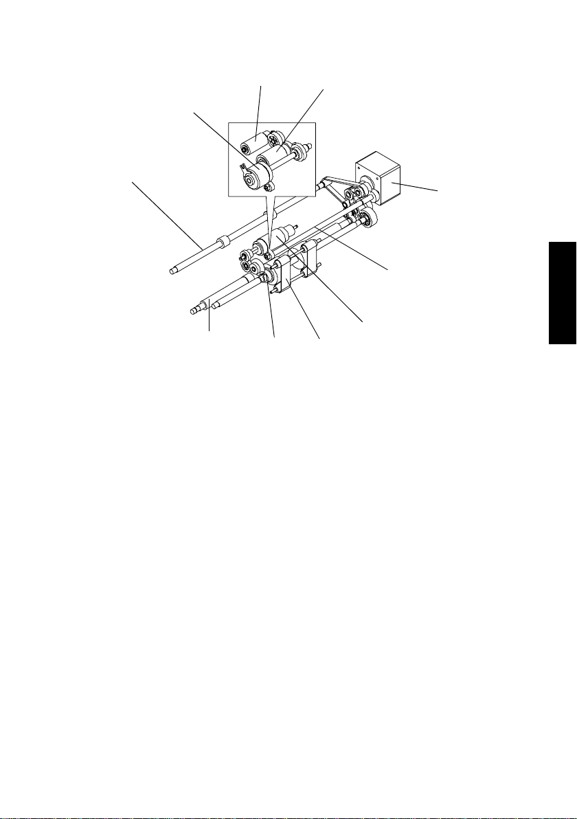
4. DRIVE SYSTEM
1
1. Exit Roller
2. Magnetic Clutch
3. Pick-Up Roller
4. Main Feed Roller
5. Main Mot or
3
2
10
9
4
7
8
6. Transfer Roller
7. Sprit Roller
8. Rubber Belt
9. Turning Roller
10. White Roller
5
6
4647G003AA
M-3
Page 9

5. ELECTRICAL COMPONENT LAYOUT
1
7
1. Document Empty Sensor (S1)
2. SDH PCB ASSY
3. Cover Sensor A (S3)
4. Main Mot or
2
3
5
6
5. Registration Sensor (S2)
6. Magnetic Clutch
7. Cover Sensor B (S4)
4
4647G004AA
6. DESCRIPTION OF MODES
✽
1-Sided Original Mode
• When a multi-page document is being used, the copier detects the size of only the first
page of the document and runs for the subsequent pages based on that size detection.
• The mode is used when making copies of a document set consisting of pages of the
same size.
M-4
Page 10

7. DOCUMENT TAKE-UP/FEEDING MECHANISM
7-1. Document Take-Up Mechanism
Pick-Up Roller
Main Motor
Main Feed Roller
Document Empty Sensor
• The document is taken up as the Pick-Up Roller and Main Feed Roller turn.
• The Pick-Up Roller transports the document up to the Main Feed Roller, moving up and
down at all times during a document take-up sequence.
• The Pick-Up Roller and Main Feed Roller are turned through the Magnetic Clutch and by
gears driven by the Main Motor.
• The Document Empty Sensor is used to detect a document loaded on the Document
Guide.
• The leading edge of the document is determined by the Sprit Roller. when the document
gets over the Sprit Roller, it stops between Main feed Roller and Sprit Roller.
Magnetic Clutch
Document stop position
4647G005AA
Main Feed Roller
Sprit Roller
4647G011AA
M-5
Page 11

7-2. Document Separating Mechanism
Pick-Up Roller
• The Sprit Roller is turned in the direction opposite to that of the Main Feed Roller, which
effectively separates the top page of the document from the rest.
• The Sprit Roller is turned by gears driven by the Main Motor.
Main Feed Roller
Sprit Roller
Main Motor
4647G006AA
M-6
Page 12

8. DOCUMENT TRANSPORT/EXIT MECHANISM
8-1. Document Transport Mechanism
Main Motor
Rubber Belt
Roller
Turning Roller
• The document taken up is transported to the document scanning position of the copier by
the Turning Roller and Rubber Belt.
• The Turning Roller and Rubber Belt are driven by gears which are driven by the Main
Motor.
8-2. Document Exit Mechanism
4647G007AA
Main Motor
Exit Roller
• The document is fed out of the ADF by the Exit Roller.
• The Exit Roller is driven by gears and a belt which are driven by the Main Motor.
4647G008AA
M-7
Page 13

8-3. Raised/Lowered Position Detection Mechanism
Magnet
ADF Set Switch
4647G009AB
• There is a magnet installed in the ADF body to allow the copier to know that the ADF is
raised or lowered.
• This magnet actuates and deactuates the ADF Set Switch on the copier.
M-8
Page 14

9. WIRING DIAGRAM
4647G010AB
JP2
TUBE
CORE
Main Motor
M
Y
R
BL
4
321
JP1
1413121110
15
BK
BR
1413121110
15
Magnetic Clutch
CL
BK
W
R
BK
2
1
JP6
8
7
9
654
Y
W
BL
PL
BK
OR
GR
BR
GY
8
7
9
654
Document Empty Sensor (S1)
PC
1
2
4
3
PJ1
R
BK
BR
OR
4
3
2
1
JP5
321
R
Y
OR
321
Registration Sensor (S2)
PC
321
PJ2
R
BL
BK
2
3
1
JP4
SDH PCB
Assy
Cover Sensor A (S3)
S
R
BK
2
1
JP7
JP3
Cover Sensor B (S4)
S
R
BK
2
1
From The
Copier
M-9
Page 15

TECH. REP. MODE
Page 16

1. OUTLINE OF USER’S CHOICE MODE
Highlighted
• User’s Choice Mode is used to make various settings according to the user’s needs.
1-1. User’s Choice Function Setting Procedure
<Setting Procedure>
1. On the copying mode screen, hold down the Exposure Control Lighter < key f or about 3
second or more.
2. Using the 1Key and 10Key, select the appropriate choice code.
3. Press the Start key to show the current setting.
4. Using the 1Key and 10Key, select the appropriate choice data.
5. Press the Start key to validate the choice data entered.
<Exiting the Mode>
• Press the Clear/Stop key.
1-2. Functions Available from the User’s Choice Mode
✽
Function available on the display only when the copier is equipped with the ADF option.
Choice Code.
U9
Setting (The default is ).
<Density (Automatic Document Feeder)>
Select the copy image density level when the copier is equipped with
an Automatic Document Feeder.
Data Description
When the standard original (text original) is used.
1
2 For sharper reproduction of a faint original.
S-1
Page 17

2. OUTLINE OF THE TECH. REP. MODE
• This mode is used by the Tech. Rep. to set, adjust, and/or program vari ous service functions.
2-1. Tech. Rep. Mode Setting Procedure
<Setting Procedure>
1. Press the following keys in this order:
Clear/Stop → Exposure Control Lighter (<) → Clear/Stop → Exposure Control Darker (>)
2. Press the 1Key until the desired Tech. Rep. sub-mode is reached. Sub-modes cycle as
follows:
Display “d” Tech. Rep. Choice “C” Function “F” Adjust “A”
3. When the code that represents the desired sub-mode is displayed, press the Start key.
4. Press the 1Key as necessary until the desired code appears on the display.
5. Press the Start key to let the copier start the sequence.
<Exiting the Mode>
• Press the Clear/Stop key.
(1) Function “F”
• Only the function which relates to ADF is described.
Code Description
<Original Passage Test>
<Test Pattern 1>
F3
F5
FE
Checks the Automatic Document Feeder for corr ect docum ent passage.
<Procedure>
1. Place paper on the Document Guide.
2. Press the Start key to let the Automatic Document Feeder start
the document take-up and feeding sequence.
Produces a test pattern for adjusting the Paper Tray for correct alignment and registration in the main scanning and sub-scanning directions.
<Original Scanning Position Contamination Test>
Checks the Automatic Document Feeder original scanning position
(Original Glass) for contamination.
<Procedure>
1. Place A4 blank paper on the original scanning part.
2. Press the Start key to let the copier produce a copy.
3. Check the copy for poss ible contamination.
S-2
Page 18

(2) Adjust “A”
Highlighted
• Only the function which relates to ADF is described.
Adjust Code
A5
Adjust the zoom ratio in the CD direction on the IR side (when the
Automatic Document Feeder is used).
Data
Description Reduced Enlarged
Setting (The default is ).
<Zoom Adjustment in CD Direction>
45................................. ................................55
50
A6
A7
A8
Adjust the zoom ratio in the FD direction on the IR side (when the
Automatic Document Feeder is used).
Data
Description Reduced Enlarged
Adjust registration in the CD direction on the IR side (when the Automatic Document Feeder is used).
Data
Description
Adjust registration in the FD direction on the IR side (when the Automatic Document Feeder is used).
Data
Description
<Zoom Adjustment in FD Direction>
45................................. ................................55
<Registration Adjustment in CD Direction>
40................................. ................................60
-5.0mm ±0 +5.0mm
<Registration Adjustment in FD Direction>
40................................. ................................60
-5.0mm ±0 +5.0mm
50
50
50
S-3
Page 19

DIS/REASSEMBLY,
ADJUSTMENT
Page 20

1. MAINTENANCE SCHEDULE
• To ensure that the copier produces good copies and to extend its service life, it is recom-
mended that the maintenance jobs described in this schedule be carried out as
instructed.
Maintenance Schedule
PM Parts
Cleaning Replacement
Sprit Roller Assembly 10 1
Pick-Up Roller 10 1
Main Feed Roller 10 1
Turning Roller 10 2
White Roller 10 1
NOTE
1. During regular maintenance visit, clean or replace parts as necessary.
2. K=1,000 originals
(K)
Qty
D-1
Page 21

2. DISASSEMBLY
2-1. Removal of the Document Cover
1. Open the ADF Cover.
4647D001AA
2
1
4647D002AA
2. Remove the Document Guide.
NOTE
Bring the Document Guide into the upright position (1)
and then pull it straight upward. (2)
2-2. Removal of the ADF Cover
1. Remove Cover 2.
NOTE
Turn Cover 2 clockwise until it stops, then remove it
together with the spring.
4647D003AA
2. Remove the two screws and ADF Cover.
4647D004AA
D-2
Page 22

2-3. Removal of the ADF Assembly
1. Remove the three screws and PCB Cover.
2. Remove the three screws and Cover 1.
Cover 1
PCB Cover
4647D005AA
1
2
3. Unplug the seven connectors from the SDH PCB
Assy.
3
7
6
4
5
4647D006AB
4. Remove the three screws and Hinge.
NOTE
Whenever the Hinge have been removed, be sure to
make the following adjustments:
• Checking and adjustment for skewed feed.
• Checking and adjustment for zoom adjust.
• Checking and adjustment for registration.
4647D018AA
NOTE
When reinstalling the Hinge, Secure it in Position with
the center .
5. Remove the five screws and ADF Assembly.
A. Front screw part is removed.
B. Rear screw part is removed.
B
C. Remove the front end first.
A
C
4647D007AB
D-3
Page 23

2-4. Removal of the Sprit Roller Assembly
1. Open the ADF Cover.
4647D008AA
2. Remove the two screws and Roller Cover.
4647D009AA
3. Unhook the spring.
4647D010AA
4647D011AA
4. Snap off the E-rings and remove the bushings.
5. Remove the Sprit Roller Assembly.
D-4
Page 24

3. ADJUSTMENT
3-1. Print of Test Pattern
(1) Entering the Tech. Rep. Mode
Procedure:
Press the following keys in this order:
Clear/Stop → Exposure Control Lighter (<) → Clear/Stop → Exposure Control Darker (>)
(2) Entering the Adjust Mode
Procedure:
1. Enter the Tech. Rep. mode.
2. Press the following keys in this order:
1Key → 1Key → 1Key → Start key → Press the 1Key until the specific function is displayed.
(3) Producing a Test Pattern
NOTE
A test pattern is used when making the following adjustments:
• Skewed Feed adjustment
• Zoom adjustment
• Registration adjustment
Procedure
1. Enter the Tech. Rep. mode.
2. Press the following key s in this order to enter the function of “F5 Test Pattern 1”:
1Key → 1Key → Start key → 1Key → 1Key → 1Key → 1Key
3. Press the Start key.
NOTE
To exit the test pattern function, press the Clear/Stop key to go back to the Basic screen.
✽
Direction where test pattern is copied
Test pattern
4647D019AA
The test pattern should be copier in one specified
direction only.
Do not copy it in the opposite direction.
D-5
Page 25

3-2. Adjustment of the Skewed Feed
(1) Check of the Skewed Feed
A
Copy
B
4647D019AA
(2) Adjustment of the Skewed Feed
✽
If A is too long and B is too short
4647D020AA
1. Set test pattern 1 in the Automatic Document
Feeder , and press the Start Key.
2. Check to see if the dimensions A and B meet the
following equation.
Requirement: A B = 1.6 mm
3. If the requirement is not met, adjust the tilt.
1. Loosen the two screws in the Hinge section and
slide the Hinge in the direction of the arrow.
2. Loosen the screw securing the reading scale, and
slide it in the direction of the arrow.
3. Make another copy and check the dimensions
again.
4647D021AA
✽
If A is too short and B is too long
4647D022AA
4647D023AA
1. Loosen the two screws in the Hinge section and
slide the Hinge in the direction of the arrow.
2. Loosen the screw securing the reading scale, and
slide it in the direction of the arrow.
3. Make another copy and check the dimensions
again.
D-6
Page 26

3-3. Adjustment of the Zoom
(1) Check of the Zoom
C
Copy
(2) Adjustment of the Zoom
d A
D
4647D019AA
2
3
1. Set test pattern 1 in the Automatic Document
Feeder , and press the Start Key.
2. Check to see if dimensions by C (main scan) and D
(sub scan) falls within the specified range.
Requirements: C 100 1.0 mm
3. If dimensions C and D fall outside the specified
range, adjust enlargement/reduction.
1. Show “d” (TEC. REP. MODE) on the display.
2. Press the 1Key as necessary until “A” appears on
the display.
3. Press the Start key.
A1
display
D 200 3.0 mm
<C (main scan) Adjust>
A1 A5
4
display
<D (sub scan) Adjust>
display
Set Value Enlargement/reduction Set Value Enlargement/reduction
6
A5 A6
8
10
45 - 2.0 % 51 0.4 %
46 - 1.6 % 52 0.8 %
47 - 1.2 % 53 1.2 %
48 - 0.8 % 54 1.6 %
49 - 0.4 % 55 2.0 %
50 0
5
5052
9
5047
4. Press the 1Key as necessary until “A5” appears on
the display.
5. Press the Start key.
6. Press the 1key or 10key to adjust the enlargement/
reduction.
• If dimension C on the copy is longer than the speci-
fied range, adjust the reduction amount.
• If dimension C on the copy is shorter than the speci-
fied range, adjust the enlargement amount.
7. Press the Start key to validate the setting value.
8. Press the 1Key as necessary until “A6” appears on
the display.
9. Press the Start key.
10. Press the 1key or 10key to adjust the enlargement/
reduction.
• If dimension D on the copy is longer than the speci-
fied range, adjust the reduction amount.
• If dimension D on the copy is shorter than the speci-
fied range, adjust the enlargement amount.
11. Press the Start key to validate the setting value.
D-7
Page 27

3-4. Adjustment of the Registration
(1) Check of the Registration
4647D025AA
1. Set test pattern 1 in the Automatic Document
Feeder , and press the Start Key.
2. Fold the copy in half, correctly aligning both edges
as shown.
E (center line)
crease
Copy
F
Copy
G
H
4647D026AA
4647D026AA
3. Check the crease and E (center line) on the copy.
• If E on the copy deviates on the G side, increase the
setting value.
• If E on the copy de viates on the H side , decrease the
setting value.
✽
Repeat these steps until the center line and crease
are aligned properly with each other.
4. Check to make sure that dimension F falls within
the range specified below.
Requirement: F 20 2.0 mm
✽
If dimension F falls outside the specified range,
adjust as necessary.
D-8
Page 28

(2) Adjustment of the Registration
d A
2
3
1. Show “d” (TEC. REP. MODE) on the display.
2. Press the 1Key as necessary until “A” appears on
3. Press the Start key.
A1
display
the display.
<E (center line) Adjust>
A1 A7
4
display
<F (left edge) Adjust>
display
Set Value Enlargement/reduction Set Value Enlargement/reduction
6
A7 A8
8
10
40 - 5.0 mm 51 0.5 mm
41 - 4.5 mm 52 1.0 mm
42 - 4.0 mm 53 1.5 mm
43 - 3.5 mm 54 2.0 mm
44 - 3.0 mm 55 2.5 mm
45 - 2.5 mm 56 3.0 mm
46 - 2.0 mm 57 3.5 mm
47 - 1.5 mm 58 4.0 mm
48 - 1.0 mm 59 4.5 mm
49 - 0.5 mm 60 5.0 mm
50 0
5
5052
9
5047
4. Press the 1Key as necessary until “A7” appears on
the display.
5. Press the Start key.
6. Press the 1key or 10key to adjust the enlargement/
reduction.
• If E on the copy deviates on the H side, change the
value to a negative (-) value.
• If E on the copy deviates on the G side, change the
value to a positive (+) value.
7. Press the Start key to validate the setting value.
8. Press the 1Key as necessary until “A8” appears on
the display.
9. Press the Start key.
10. Press the 1key or 10key to adjust the enlargement/
reduction.
• If dimension F is longer that the specified range,
change the value to a negative (-) value.
• If dimension F is shorter that the specified range,
change the value to a Positive (+) value.
11. Press the Start key to validate the setting value.
D-9
Page 29

TROUBLESHOOTING
Page 30

1. INTRODUCTION
1-1. Reading the Text
1. The paper transport failure troubleshooting procedures are given according to the
symptom. First, identify the location where the paper is present and start the procedure
for that particular location. For malfunction troubleshooting, start with step 1 and
onward.
2. Make checks in the numerical order of steps and, if an item is checked okay, go to the
next step.
Pattern 1
Step Check Result Action
1~ YES~
2
Go to step 2 if you answered No.
Pattern 2
Step Check Result Action
1~ YES ~
2
Go to step 2 if it checks okay.
2. PAPER TRANSPORT FAILURE
2-1. Paper Misfeed
When a document misfeed occurs, the display shows “J8.”
<Resetting misfeed display>
Open the relevant cover, remove the misfeed, and close the cover.
Symptom
• The document
is not properly
detected when
it is loaded.
• The document
is not taken up
at all.
Step
No.
1 Is the Document Empty
1 Does the Pick-Up Roller
2 Is the Main Motor ener-
3 After exchanging the SDH
Check Item Result Action
YES Check cables and conSensor operational, as
checked through a sensor
check?
NO Check the actuator for
NO Check the drive transmit-
press the document?
YES Check the drive transmitgized?
NO Check Main Motor cables
NO Change the Main Motor.
PCB Assy: Is the Main
Motor energized?
NO ~
nectors for connection.
Change the SDH PCB
Assy.
operation and, if it is
intact, change the sensor.
ting gears.
Check the Pick-Up Roller
Spring.
ting gears up to the Main
Feed Roller.
and connectors (JP2) for
connection.
T-1
Page 31

Symptom
• Multiple feed of
document
pages occurs.
• The document
stops midway.
Step
No.
1 Does the document being
used fall outside the category of reliable feeding?
2 Has the capacity of the Doc-
ument Guide been
exceeded?
3 Is any of the Pick-Up Roller,
Main Feed Roller, and Sprit
Roller deformed, worn, or
dirty with paper dust?
4 Is the Sprit Roller pressed
against the Main Feed
Roller?
1 Is a foreign object present
along the document path?
2 Is the ADF Cover closed in
position?
3 Is the Registration Sensor
operational, as checked
through a sensor check?
4 Is any of the Turning Roller,
Rubber Belts, and Exit
Roller deformed, worn, or
dirty with paper dust?
5 Does the Turning Roller or
Exit Roller turn?
Check Item Result Action
YES Instruct the user to use
the document that meets
the specifications for reliable feeding.
YES Instruct the user not to
exceed the capacity.
YES Clean or change the
defective roller.
NO Check the spring.
YES Change the Sprit Roller
Assy.
YES Remove the foreign
object.
NO Close the cover in posi-
tion.
YES Change the SDH PCB
Assy.
NO Check the actuator for
operation and, if it is
intact, change the sensor.
YES Clean or change the
defective part.
NO Check the drive transmit-
ting gears and belt.
T-2
Page 32

Symptom
• The document
is fed in askew.
• The document
wrinkles or
breaks.
Step
No.
1 Is a foreign object present
2 Is the ADF Cover closed in
3 Does the document consist
4 Is any of the rollers
1 Does the document being
2 Has the capacity of the Doc-
3 Is a foreign object present
4 Is any of the rollers
Check Item Result Action
along the document path?
position?
of pages of different sizes?
deformed, worn, or dirty with
paper dust?
used fall outside the category of reliable feeding?
ument Loading Tray been
exceeded?
along the document path?
deformed, worn, or dirty with
paper dust?
YES Remove the foreign
object.
NO Close the cover in posi-
tion.
YES Align one edges properly
when loading the document.
YES Clean or change the
defective roller.
YES Instruct the user to use
the document that meets
the specifications for reliable feeding.
YES Instruct the user not to
exceed the capacity.
YES Remove the foreign
object.
YES Clean or change the
defective roller.
3. MALFUNCTION DETECTION
Any of the following operation faults can be detected and the corresponding malfunction
code is shown on the Copier Display.
3-1. Display “oA”
It is displayed when the ADF Cover is not in correct position.
Symptom
•“oA” display
does not disappear.
Step
No.
1 Is the ADF Cover closed in
2 Is the Cover Sensor A and B
3 Check Sensor cables and
4 After exchanging the SDH
Check Item Result Action
position?
deformed or dirty with paper
dust?
connectors (JP3, 7)
PCB Assy: Is the Main
Motor energized?
NO Close the cover in posi-
NO Clean or change the
NO Reconnect the cables and
NO Change the Cover Sensor
T-3
tion.
defective Sensor.
connectors.
A and B.
 Loading...