

Konica 7115-18 Service Manual pf121e

PF-121
SERVICE MANUAL

CONTENTS
GENERAL, MECHANICAL/ELECTRICAL
1. SPECIFICATIONS ........................................................................................... M-1
2. COMPONENT IDENTIFICATION .................................. ........................... .......M-1
3. CROSS-SECTIONAL VIEW ............................................................................M-2
4. DRIVE SYSTEM COMPONENT LAYOUT ......................................................M-2
5. ELECTRICAL PARTS LAYOUT ......................................................................M-3
6. PAPER TAKE-UP/FEEDING SECTION ..........................................................M-4
6-1. Edge Guide and Trailing Edge Stop ........................................................M-4
6-2. Paper Lifting Plate ...................................................................................M-4
6-3. Tray-in-Position Detection ........................ ...............................................M-5
6-4. Paper Empty Detection . ...........................................................................M-5
6-5. Paper Size Detecting Mechanism ............................................................M-6
6-6. Paper Separating Mechanism .................................................................M-7
6-7. Paper Take-Up Control . ...........................................................................M-8
6-8. Paper Take-Up Retry Control ..................................................................M-9
DIS/REASSEMBLY, ADJUSTMENT
1. DISASSEMBLY ...............................................................................................D-1
1-1. Maintenance Schedule ................................................................... .... .. ...D-1
1-2. Removal of the Paper Take-Up Rollers ...................................................D-2
1-3. Cleaning of the Paper Take-Up Roller/Rolls ............................................D-2
1-4. Cleaning of the Vert ical Transport Roller/Rolls ........................... .............D-3
2. ADJUSTMENT .................................................................................................D-4
2-1. Adjust Mode Setting Procedure ........................................................ .... ...D-4
2-2. CD Registration Adjus tment ............... .............. ............................ ...........D-4
MISFEED DETECTION
1. MISFEED DETECTION ................... ............................ .............. ......................T-1
1-1. Location of Misfeed Detecting Sensors ...................................................T-1
1-2. Misfeed Detection Timing ........................................................................T-2
i

GENERAL,
MECHANICAL/ELECTRICAL
1. SPECIFICATIONS
Type : Paper Feed Cabinet
Installation : Installs in the bottom of the Main Unit.
(Fixed to the Main Unit by plates and screws.)
Type of Copy Paper :
Paper Sizes : Metric Areas: A5, B5/B5R, A4/A4R, F4, B4R, A3R
Registration : Center
Capacity : 250 sheets
Power Requirements : DC24 V, DC5 V (supplied from copier)
Max. Power Consumption : 9 W or less
Dimensions : Width: 590 mm or 23-1/4
Weight : 5.5 kg or 12-1/4 lbs.
Plain paper, Recycled paper (60 to 90 g/m
Inch Areas: 8-1/2
Depth: 558 mm or 22
Height: 108 mm or 4-1/4
× 5-1/2, 5-1/2 × 8-1/2R, 11 × 8-1/2,
8-1/2
× 11R, 8-1/2 × 14R, 11 × 14, 11 × 17
2
or 16 to 24 lbs.)
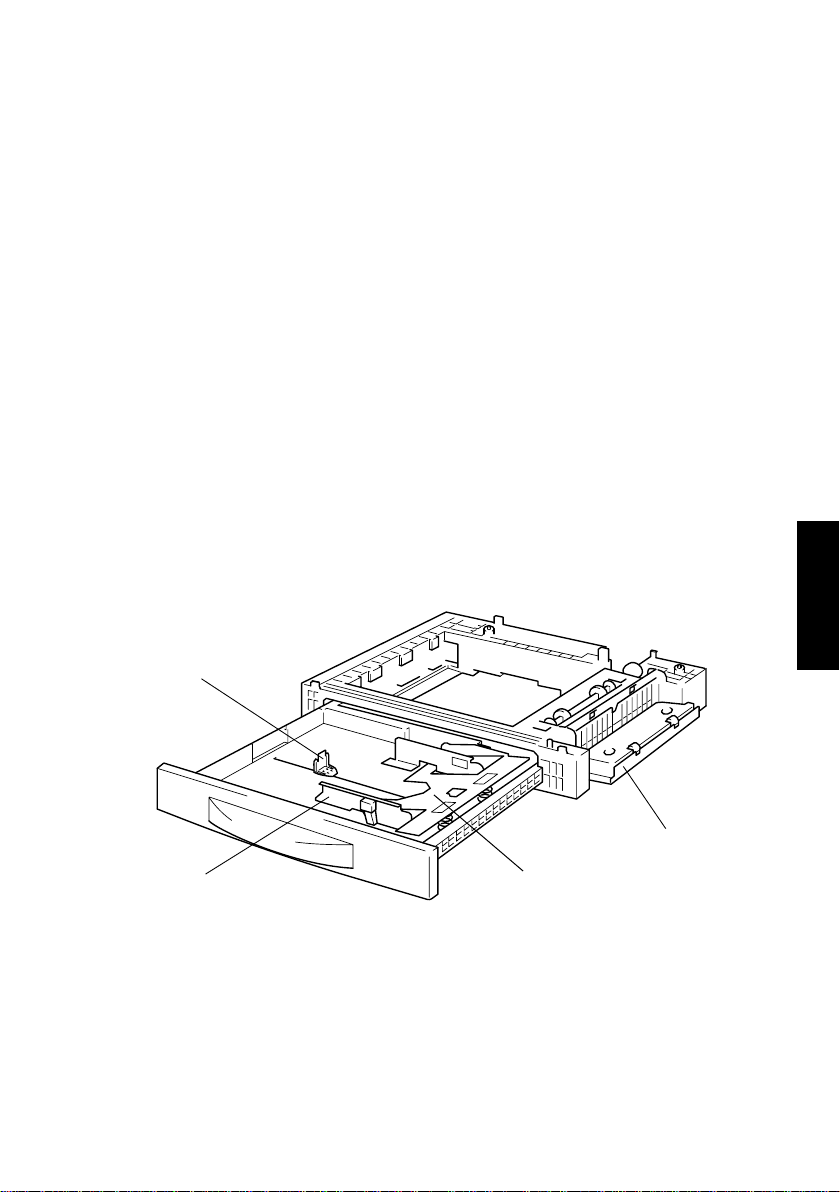
2. COMPONENT IDENTIFICATION
1
1. Trailing Edge Stop 3. Paper Lifting Plate
2. Side Door 4. Edge Guide
M-1
2
34
4686M011AA

3. CROSS-SECTIONAL VIEW
234
1
5678
1. Paper Take-Up Roll 5. Paper Lifting Spring
2. Paper Take-Up Roller 6. Paper Lifting Plate
3. Vertical Transport Roller 7. Edge Guide
4. Vertical Transport Roll 8. Trailing Edge Stop
4. DRIVE SYSTEM COMPONENT LAYOUT
4686M001AC
Paper Take-Up
Drive Mechanism
Vertical Transpor t Roller
Paper Take-Up Roller
4686M003AA
M-2
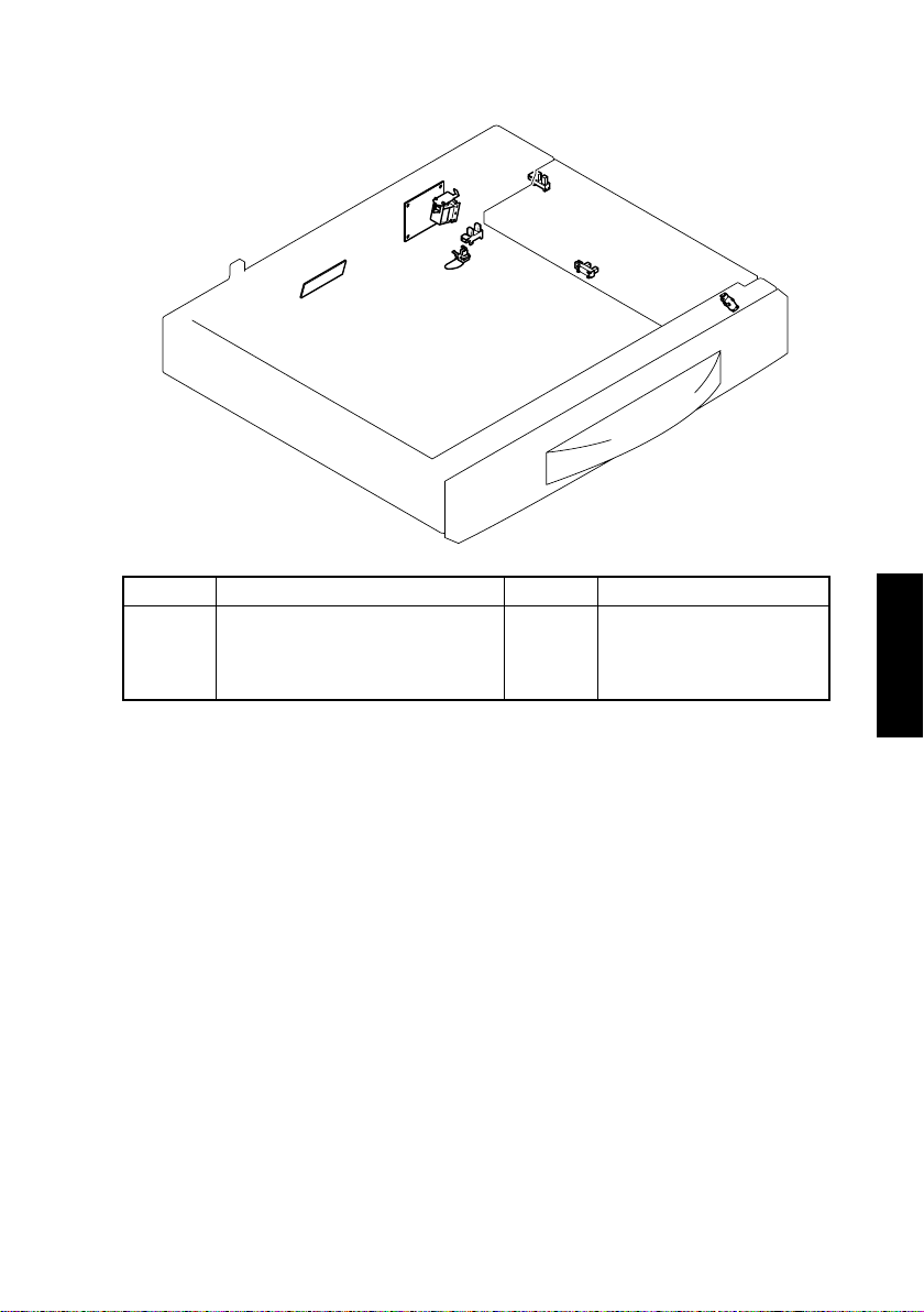
5. ELECTRICAL PARTS LAYOUT
SL11
PWB-A
PC13
PWB-I
Symbol Name Symbol Name
PWB-A
PWB-I
S11
SL11
Control Board
Paper Size (FD) Detection Board
Paper Size (CD) Detection Sensor
Paper Take-Up Solenoid
S11
PC14
PC11
PC12
PC13
PC14
PC11
PC12
Paper Empty Sensor
Paper Take-Up Sensor
Drawer Set Sensor
Side Door Sensor
4686M012AA
M-3
 Loading...