

Konica 7115-18 Service Bulletin
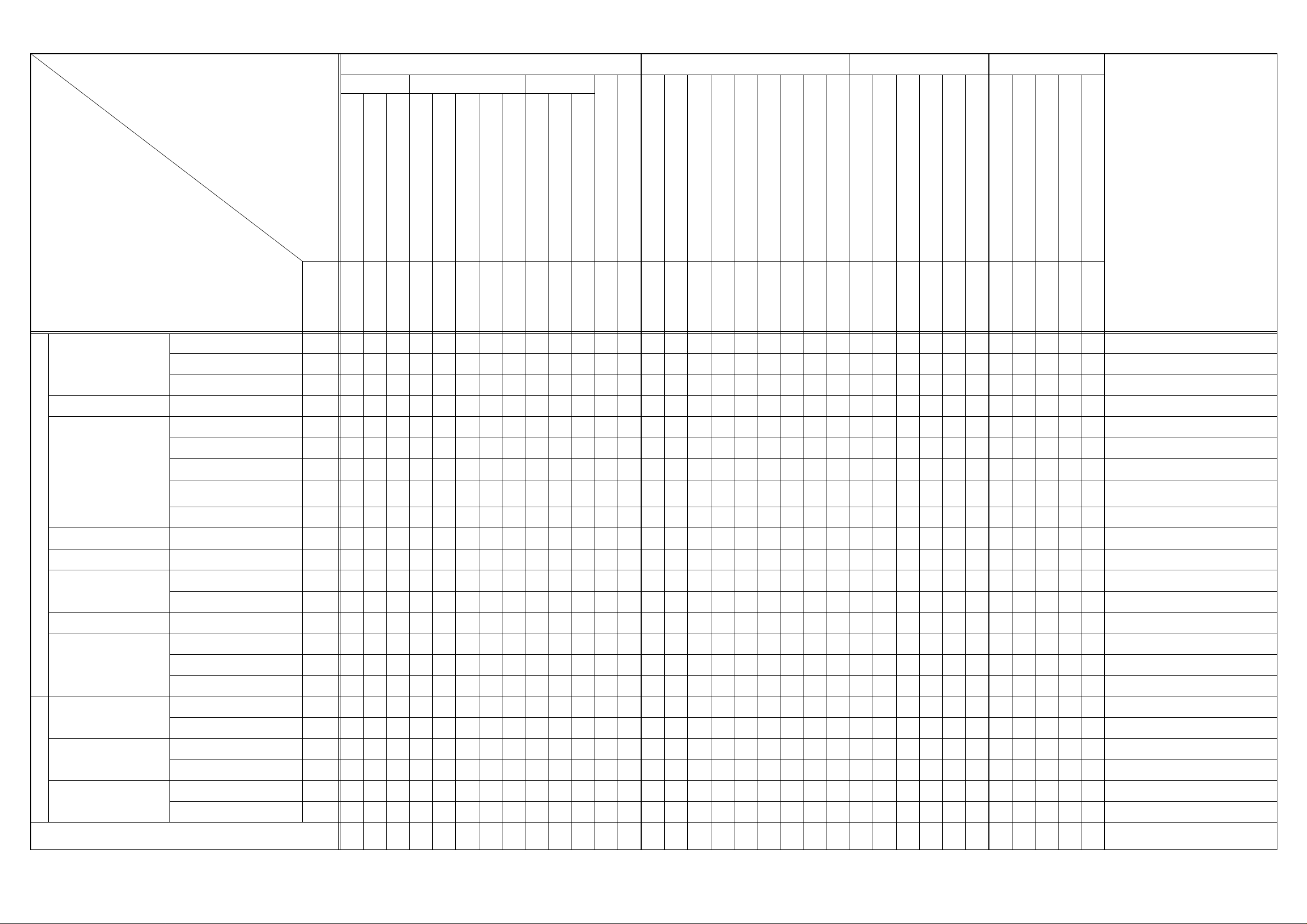
Service/Adjustment Item List
Adjustment/Settin g Ite m s
Service Items
Tech.Rep.Mode Adjust Mode Mechanical Others
Function Tech.Rep.Choice Counter
Paper Pa ssage Test
ATDC Sensor Automatic Adjustment
Test Pattern Output
ID Adjustment
VG Adjustment
Loop Length Adjustment (1st Tray)
Loop Length Adjustment (2nd- 5th Tray)
Loop Length Adjustment (Bypass Tray)
PM Counter
Note
ADF Document Passage Test
Scanner Drive Check
Printer CD Registration Adjustment
Printer FD Registration Adjustment
Scanner CD Zoom Adjustment
Scanner FD Zoom Adjustment
Scanner CD Registration Adjustment
Scanner FD Registration Adjustment
ADF FD Zoom Adjustment
ADF CD Registration Adjustment
ADF FD Registrat ion Adjustment
Application of toner to PC Drum
Focus-Positioning of Scanner and 2nd/3rd Mirrors Carriage
Scanner Motor timing belt tension adjustment
CCD Unit position adjustment
Multiple Bypass position adjustment
Manual Bypass registration adjustment
Re-setting of various functions
Remount EEP ROM (U29)
Adjust Label
Change of developer
Maintenanc e Counter
IU Life Counter
Application of lubricant
Check
Items
Paper Take-Up Roll (1st Tray) Replace
Paper Take-Up/Transport Section
Optical Section Scanner Rail/Bushing Clean
Imaging Unit Sectio n
PM
Image Transfer Section Image Transfer Roller Assy Replace
Fusing Section Fusing Unit Replace
Multiple Bypass (Option)
Paper Separator Roll Assy (1st Tray) Replace
Cleaning P ad Replace
PC Drum Replace
Cleaning Blade Replace
PC Drum Charge Corona Ass y Replace
Developer Replace
Ozone Filter Replace
Paper Take-Up Roll Replace
Paper Separator Roll Assy Replace
|
||||||
Automatic Adjustment
||
20±2.0 mm
20±1.5 mm
Clear Counter
Clear Counter
Clear Counter
200±2.0 mm
20±2.0 mm
300±3.0 mm
20±1.5 mm
20±2.0 mm
300±4.5 mm
|
20±2.5 mm
|
Jig
Jig
200±2.0 mm
Re-input
0±2.0 mm
23*1
23*1
1*
31 2
12
32* 1
2*,4 3* 1 4
1
1
1
45*1 23
23*1
||
Remount
write down the data
* Check when setting is changed.
* Check when setting is changed.
* When maintenance counter i s set.
1
* Check when setting is changed.
2* Run F8 twice before removing the PC Drum Unit.
3* Check when setting is changed.
* Check when setting is changed.
* Check when setting is changed.
Paper Feed cabinet (Option) Paper Take-Up Roller Replace
Pick-Up Roller Replace
Automatic Document Feeder (Option)
Electrical Parts
Units
Others
Parts other than PM Parts
Paper Take-Up Roller Replace
Paper Separator Roller Replace
ATDC Sensor Replace
Control Board (PWB-C) Replace
PH Unit Replace
CCD Unit Replace
Memory Clear
Scanner Drive Cable Install
Ref.Page S-13
23*1
12
12
12
1*,3 42
D-30
S-13 S-13 S-13 D-54 D-54 D-54 S-13 S-13 S-13 S-1* S-13 D-55 D-56 D-59 D-60 D-57 D-58 D-8* D-9* D-10* D-34 D-64 D-51 D-65 D-42 D-63
D-61
123456789
23 4 1
345 21
1
1
|
D-70
|
D-30 D-22 * Ref. page of DF-21 7 Service Ma nual.
NOTES: Before executing a Memory Clear, be sure to take notes of the settings and adjustment data of Utility, Tech. Rep., Security, and Adjust modes. After the Memory Clear has been executed, re-enter those data.
: The following data of Adjust mode are indicated at the factory on the Adjust Label located inside the Front Door: Printer CD Registration (1st Tray), Printer FD Registration, Scanner CD Zoom, Scanner FD Zoom, Scanner CD Registration, and Scanner FD R egistration.
: The ATDC value at the time of setting up of the PC Drum Unit is also entered on the Adjust Label at installation.
* Check when setting is changed.
* Run F8 twice before removing the PC Drum Unit.
4021-7993-11
 Loading...