

Komatsu PC800-8, PC850-8 Service Manual


CONTENTS
Specifications...................................................................................................................... 1
Precautions for Field Assembly .......................................................................................... 2
Assembling Procedures, Applicable Equipment and Schedule .......................................... 3
Kit Layout Diagram ............................................................................................................. 4
Transportation..................................................................................................................... 5
List of Tools for Field Assembling....................................................................................... 11
Tightening Torque...............................................................................................................12
Coating Materials................................................................................................................ 16
A. Assembly of Base Machine............................................................................................ 19
A- 1. Installation of Left and Right Track Frames........................................................... 20
A- 2. Installation of Travel Pipe ...................................................................................... 24
A- 3. Installation of Top Guard ....................................................................................... 27
A- 4. Installation of Radiator Cover ................................................................................ 28
A- 5. Installation of Rearview Mirror ............................................................................... 29
A- 6. Installation of Left Side Step .................................................................................. 33
A- 7. Installation of Handrail ........................................................................................... 34
A- 8. Installation of Handrail (With top guard) ................................................................ 35
A- 9. Installation of Muffler Tail Tube.............................................................................. 37
A-10. Sticking Sheet to Counterweight ........................................................................... 38
A-11. Installation of Counterweight ................................................................................. 39
A-12. Installation of ORBCOMM Antenna (if equipped).................................................. 40
A-13. Installation of Step Light ........................................................................................ 41
A-14. Air Bleeding of Travel Motor .................................................................................. 43
A-15. Installation of Travel Piping Cover......................................................................... 44
A-16. Testing Track Shoe Tension.................................................................................. 46
A-17. Check Fuel, Coolant and Oil Levels ...................................................................... 49
A-18. Parts to be Touched up after Field Assembly........................................................ 52
B. Assembling of Work Equipment of Backhoe .................................................................. 53
B- 1. Assembly of Arm Cylinder ..................................................................................... 54
B- 2. Connection of Arm Cylinder Hoses........................................................................ 55
B- 3. Installation of Boom Cylinder Foot......................................................................... 57
B- 4. Relieving Remaining Pressure from Hydraulic Circuit........................................... 58
B- 5. Installation of Boom Cylinder Hoses...................................................................... 59
B- 6. Assembly of Boom Assembly ................................................................................ 60
B- 7. Hose Connection of Arm and Bucket Circuits........................................................ 61
B- 8. Installation of Quick Return Hose .......................................................................... 62
B- 9. Installation of Boom Cylinder ................................................................................. 63
B-10. Installation of Arm Assembly ................................................................................. 64
B-11. Installation of Hose between Boom and Bucket Cylinder...................................... 66
B-12. Installation of Bucket Assembly............................................................................. 67
B-13. Lubrication Piping to Work Equipment .................................................................. 68
B-14. Air Bleeding from Cylinder..................................................................................... 69
B-15. Wiring of Work Equipment..................................................................................... 70
B-16. Greasing after Assembling Work Equipment......................................................... 71
M. Procedure for Inspection and Maintenance after Completion of Assembly ................... 73
M- 1. Inspection of Oil Level in Hydraulic Tank and Refill.............................................. 74
M- 2. Replacement of Return Filter (Standard Filter to Flushing Filter).......................... 76
M- 3. Flushing of Hydraulic Circuit ................................................................................. 79
M- 4. Error Code............................................................................................................. 81

C. Assembling of Work Equipment of Loading Shovel..................................................... 83
C- 1. Releasing residual pressure in hydraulic circuit.................................................. 84
C- 2. Pulling out boom foot pin and boom cylinder foot pin ......................................... 85
C- 3. Installation of boom and arm assembly............................................................... 86
C- 4. Installation of flushing piping between chassis and boom .................................. 87
C- 5. Installation of flushing piping for boom cylinder and arm cylinder....................... 88
C- 6. Installation of flushing piping for bucket cylinder................................................. 89
C- 7. Installation of flushing piping for bottom dump cylinder ...................................... 90
C- 8. Installation of boom cylinder................................................................................ 92
C- 9. Installation of boom cylinder foot......................................................................... 93
C-10. Installation of boom cylinder hoses..................................................................... 94
C-11. Installation of boom cylinder rod pin ................................................................... 95
C-12. Installation of arm cylinder hoses........................................................................ 96
C-13. Installation of bucket cylinder.............................................................................. 97
C-14. Installation of bucket cylinder hose ..................................................................... 98
C-15. Installation of connecting hoses between chassis and boom top ....................... 99
C-16. Installation of bottom dump cylinder hoses......................................................... 100
C-17. Installation of bucket assembly ........................................................................... 101
C-18. Installation of working lamps............................................................................... 103
C-19. Installation of work equipment grease piping...................................................... 104
C-20. Greasing after assembling of work equipment.................................................... 105
C-21. Bleeding air from work equipment circuit............................................................ 106
C-22. Checking oil level in hydraulic tank and adding oil.............................................. 107
C-23. Replacement of Return Filter (Standard Filter to Flushing Filter) ....................... 108
C-24. Flushing of Hydraulic Circuit ............................................................................... 111
Field Assembly Inspection Report (Backhoe)
Field Assembly Inspection Report (Loading Shovel)
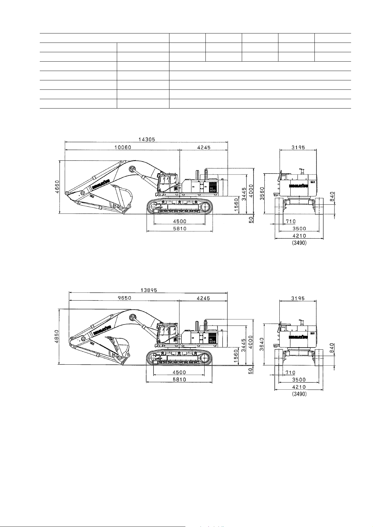
SPECIFICATIONS
Machine model PC800-8 PC800LC-8 PC800SE-8 PC850-8 PC850SE-8
Weight of machine kg 75,000 77,200 76,000 79,500 79,100
Bucket capacity m
Engine model – SAA6D140E-5
Flywheel horsepower kW/rpm {HP/rpm} 363/1,800 {486/1,800}
Min. ground clearance mm 840
Travel speed (Low/High) km/h 2.8/4.2
Swing speed rpm 6.8
3
PC800-8
3.1 3.1 4.0 3.4 4.3
PC850-8
aThe figures in ( ) show the value when the track width is reduced.
aThe figures in ( ) show the value when the track width is reduced.
1

PRECAUTIONS FOR FIELD ASSEMBLY
1. Selection of workplace
1) When selecting a workplace, consider the following items so that you can load and unload the machine.
• Width
• Hardness
• Flatness
• Access road, place for turn
2) Do not work in a place where dust, rainwater, etc. may enter the hydraulic circuit during assembling work.
3) Do not assemble while a strong wind is blowing or it is raining.
2. Preparation and check of slings and tools
1) Check each sling and tool thoroughly. When using wood blocks, etc., check that their inside is
not rotten or broken.
3.
Check of actual work
1) Apply the parking brakes of the trailer and crane truck securely and put chocks under their
wheels.
2) Before starting the work lower the temperature and pressure of the engine oil, hydraulic oil,
cooling water, etc.
3) When starting the engine, make an arranged sign such as sounding of the horn and check that
the work equipment control lever and travel lever are in neutral and the fuel control dial (or fuel
control lever) is at the low idling position.
4) When using the crane, balance the load.
5) Allow only the persons concerned into the workplace.
4. Before starting the work, read this manual thoroughly and keep the precautions in your mind.
The numbers in circles in the illustrations correspond to the numbers in ( ) in the text. (For example q ➝ (1))
5. The supervisor shall write down the precautions for each work process and explain them to the workers.
6. Hold a meeting every morning to check today's work plan and safe work.
2
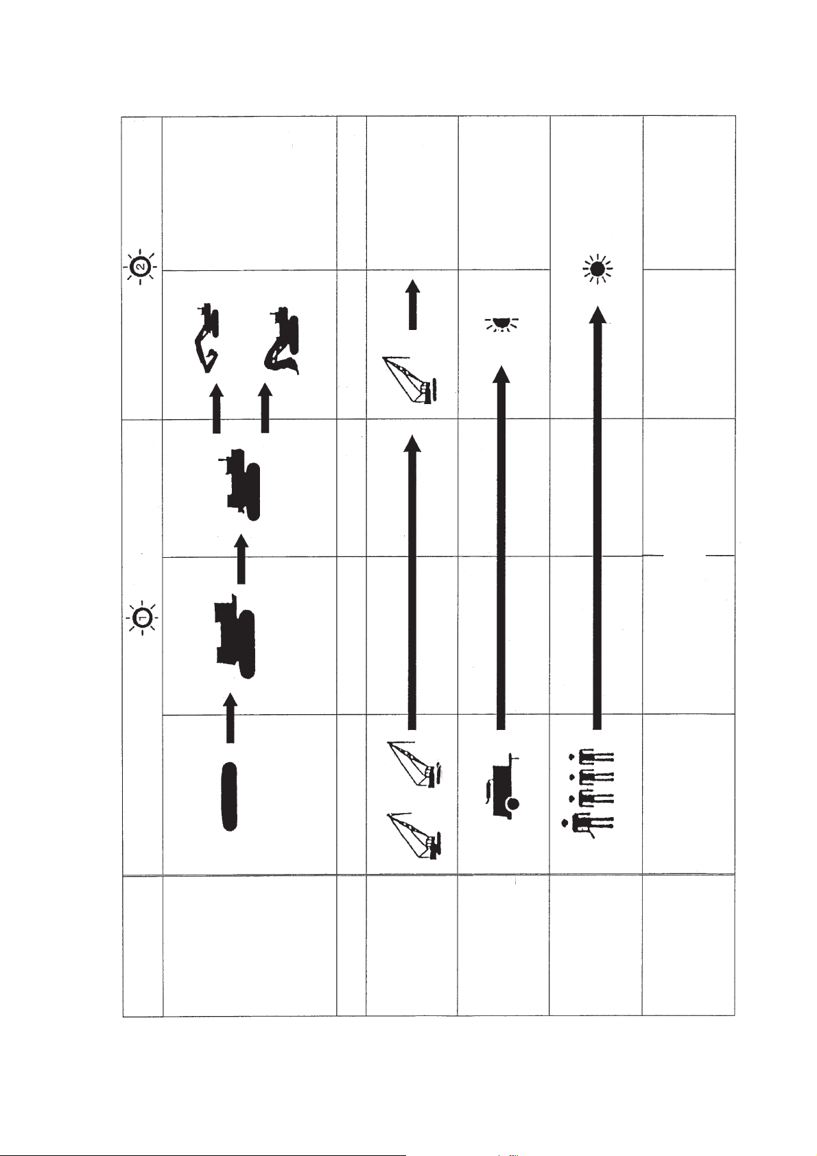
ASSEMBLING PROCEDURES, APPLICABLE EQUIPMENT AND SCHEDULE
4 Divisions
· Inspection of oil level and
coolant level
· Air bleeding from work
equipment cylinder
· Flushing of hydraulic
circuit
· Adjustment of track
tension
· Performance test
Backhoe
Loading shovel-
type excavator
u Assembling of work
equipment
35t
· Completion of general
assembling
Completion of body
assembling
Platform group
· Inspection of oil
t Counterweight
y
r Upper structure
Base machine
q Left track frame
w Right track frame
e Axle assembly
level and coolant level
(Two)
45t 45t
)
2
0.49 -- 0.69 MPa
(5 -- 7 kg/cm
/min
3
15 m
Leader + 3 mechanics
· Meeting with all workers Completion of Installation of unit assembly to body
Start of assembling
Days
Assembly unit
Crane
3
Air compressor
Worker
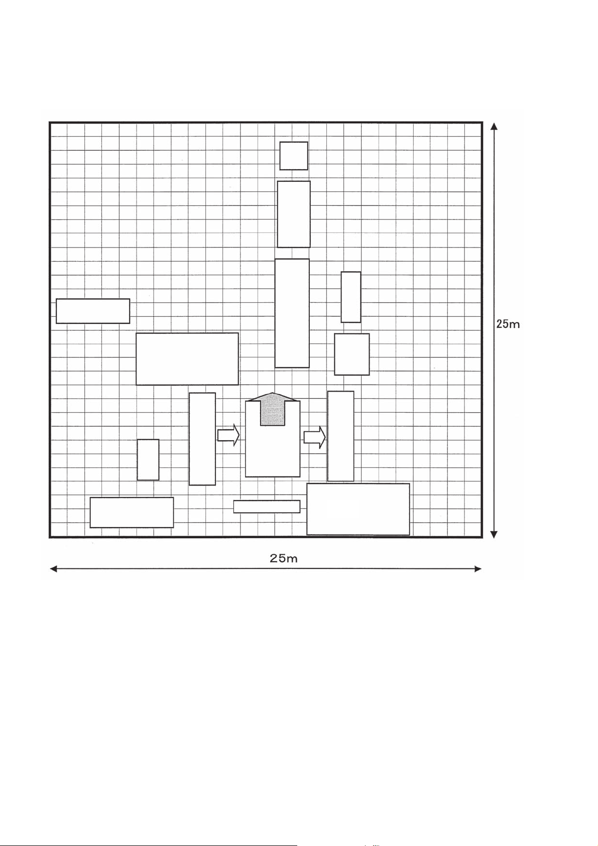
KIT LAYOUT DIAGRAM
• The dimensions given below are the minimum dimensions needed.
• The kit dimensions in the diagram are outline dimensions.
• When selecting a place, see precautions for “FIELD ASSEMBLING”.
Bucket
Arm link
Tools, facility
Motor cover · handrails
45t crane
Left deck
Crawler frame
Counterweight
Boom
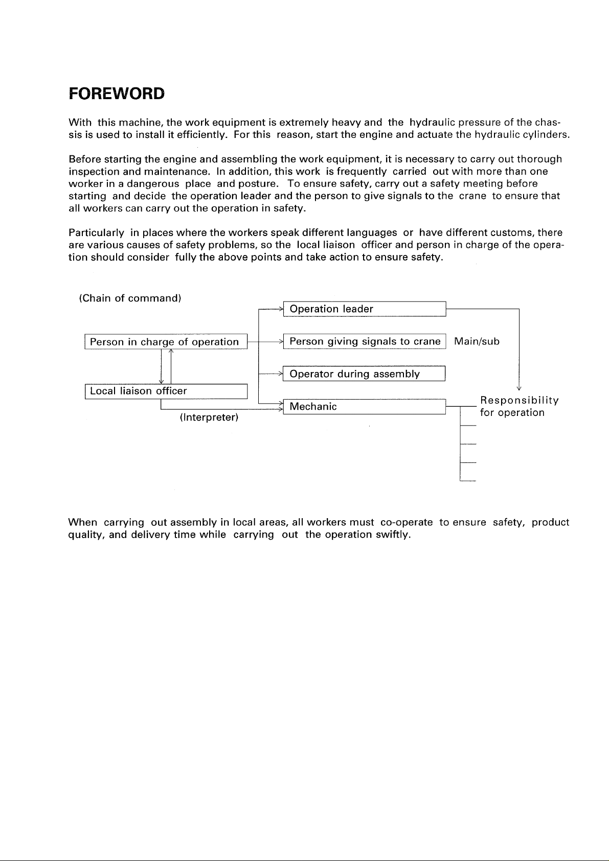
Foreword
Revolving
frame
Arm cylinder
Boom
cylinder
Crawler frame
45t crane
4
TRANSPORTATION
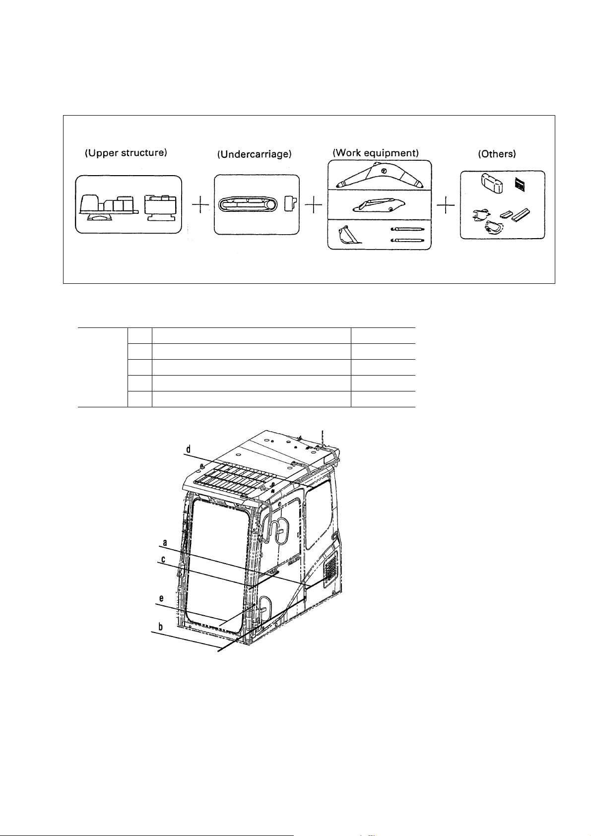
Packing Style for Transportation
These machines can be divided into three or four kits for transportation. Please ask us or our service shop for
transportation.
t 4-kit Transportation
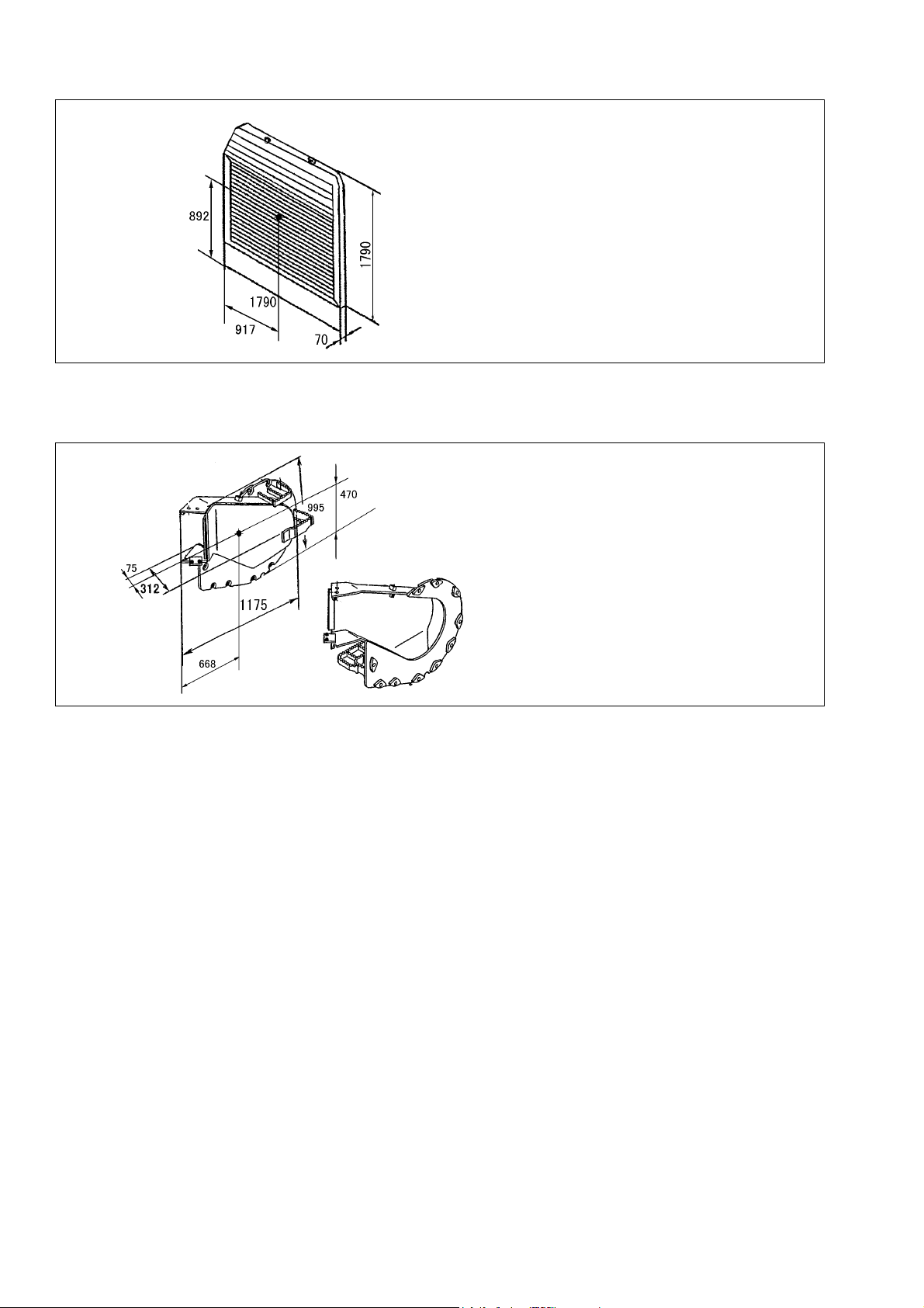
t Packing Style of Each Kit (Sizes in drawing are given in millimeters.)
• Upper structure (single piece of cab)
Full width
(mm)
a Cab convex portion (air intake for air conditioner) 3,219
b Door hinge 3,204
c Lock used when the door is opened 3,262
d Stopper used when the door is opened 3,287
e Handrail 3,220
5
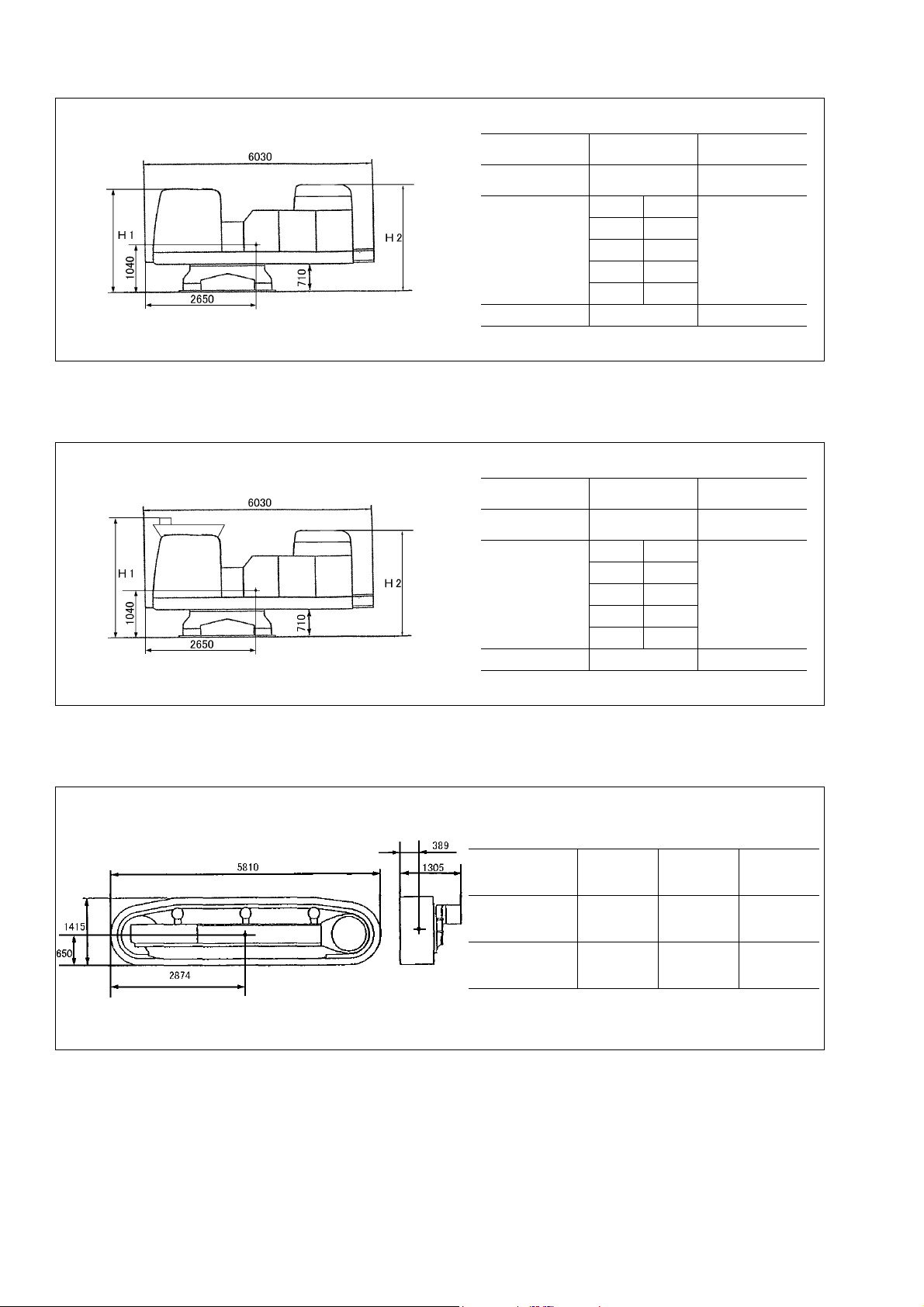
• Upper structure without head guard
Unit: mm
• Upper structure with head guard
Unit: mm
Fix the upper structure on the truck by means of chain block.
Equipped
with cab
Overall height
(mm)
Overall width
(mm)
Weight (kg) 25,620 25,080
* Revolving frame
Overall height
(mm)
Overall width
(mm)
Weight (kg) 25,770 25,180
* Revolving frame
H1: 2,840 H2: 2,840
a3,204
b3,220
c3,262
d3,219
e3,287
Equipped
with cab
H1: 2,910 H2: 2,840
a3,204
b3,220
c3,262
d3,219
e3,287
Not equipped
Not equipped
with cab
*3,195
with cab
*3,195
• Undercarriage
Unit: mm
Model
Quantity 2 2 2
Weight (kg)
PC800-8
PC800SE-8
21,500
(10,750×2)
PC850-8
PC850SE-8
22,000
(11,000×2)
PC800LC-8
(11,800×2)
23,600
6
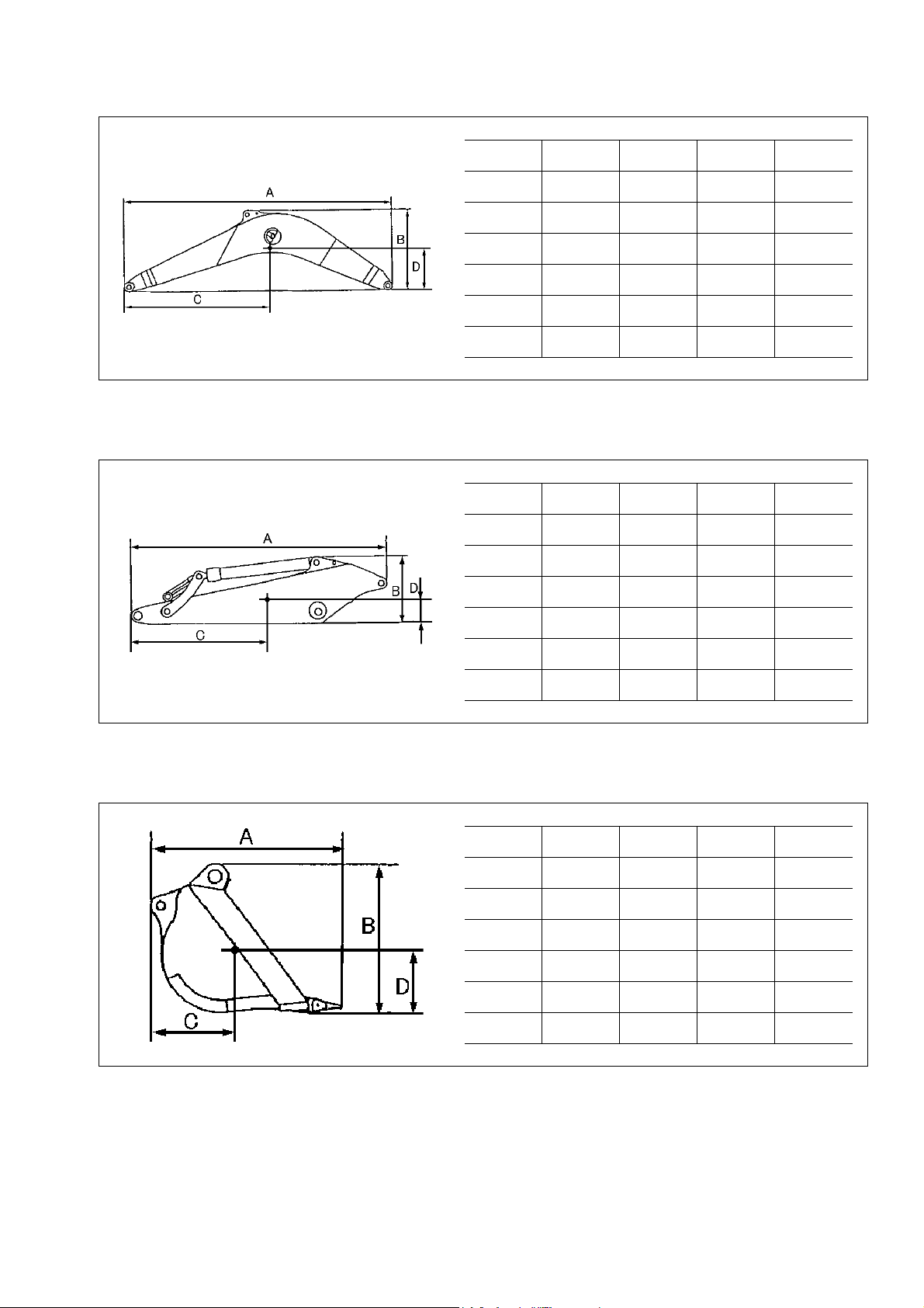
• Work equipment
(1) Boom
(2) Arm
Model
A (mm) 8,505 7,405 8,345 7,405
B (mm) 2,705 2,560 2,695 2,560
C (mm) 4,387 4,104 4,295 4,104
D (mm) 1,218 1,098 1,210 1,098
Overall
width (mm)
Weight
(kg)
Model
A (mm) 5,105 4,075 4,800 4,075
B (mm) 1,324 1,696 1,410 1,696
C (mm) 2,459 2,237 2,478 2,237
PC800-8
PC800LC-8
1,500 1,500 1,500 1,500
7,510 6,950 7,770 6,950
PC800-8
PC800LC-8
PC800SE-8 PC850-8 PC850SE-8
PC800SE-8 PC850-8 PC850SE-8
(3) Bucket
D (mm) 577 709 648 709
Overall
width (mm)
Weight
(kg)
Model
A (mm) 2,365 2,200 2,390 2,200
B (mm) 1,850 1,950 1,880 1,950
C (mm) 1,052 889 1,118 889
D (mm) 646 714 599 714
Overall
width (mm)
Weight
(kg)
749 753 749 753
3,970 4,880 4,485 4,880
PC800-8
PC800LC-8
1,845 2,105 1,870 2,255
2,960 3,420 3,840 4,245
PC800SE-8 PC850-8 PC850SE-8
7
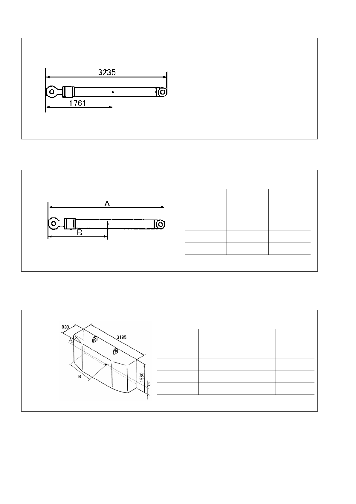
(4) Boom cylinder (for all models)
(5) Arm cylinder
Weight: 1,550 kg
(775 kg × 2 pcs)
• Others
(1) Counterweight
Unit: mm
Model
Quantity 1 2
A (mm) 3,500 2,595
B (mm) 1,885 1,391
Weight
(kg)
Model
A (mm) 451 451 451
B (mm) 1,689 1,689 1,689
PC800-8
PC800SE-8
PC800-8
PC800LC-8
870 986 (493 × 2)
PC850-8
PC850SE-8
PC800SE-8
PC850-8
PC850SE-8
PC800LC-8
(If equipped)
C (mm) 684 684 684
Weight
(kg)
9,740 11,890 13,600
8

(2) Top guard (PC850-8, PC850SE-8 only)
(3) Catwalk (1) (for all models)
Unit: mm
Weight: 55 kg
Unit: mm
Weight: 49 kg
(4) Catwalk (2) (for all models)
Unit: mm
Weight: 31 kg
9
(5) Radiator duct (for all models)
(6) Travel motor cover (for all models)
Unit: mm
Weight: 81 kg
Weight: 115 kg × 2
10

LIST OF TOOLS FOR FIELD ASSEMBLING
No. Tool names Specifications Q’ty. Remarks
1
2 Crane truck 441 kN {45 ton}, 245 kN {25 ton} 1 each
3 Grease pump Air type 1 Work equipment lubrication
4 Stepladder 5 -stepped- 1500 mm 2
5
6 KW12PI (For M12) 1
7 KW20P (For M16) 1
8 KW45FS (Spline) 1 For counterweight
9 Socket for KW45FS Spline × 65 mm 1 For counterweight
10 Air hose 50 m 1 For impact wrench
11 16-time wrench 4413 Nm {450 kgm} 1 For counterweight
12
13 T38.1 × 55 mm 1 For track frame
14 T38.1 × 50 mm 1 For track frame
15 4-time wrench 25.4, 19 1
16
17 T25.4 × 55 mm 1
18
19 834 Nm {85 kgm} – T25.4 mm 1 For 4-time wrench
20 4118 Nm {420 kgm} – T38.1 mm 1
21 Standard tool Socket, spanner, wrench 2 set
22 Sledge hammer 10 P 1
23 Bar 1 m 2
24
25 196 kN {20 ton} 1
26 Waste oil pan Large, small 2 each
27 Wooden block 300 × 400 mm 4 Revolving frame pedestal
28
29 ø20 × 5 m 2 For boom, arm and bucket
30 ø25 × 5 m 4
31 ø30 × 5 m 2 For counterweight
32
33 SC18 4
34 Nylon sling 50 mm wide × 3 m 2
35 Pin ø50 × 5 m 2 Track frame
36 Lever block 14.7 – 29.4 kN {1.5 – 3 ton} 2
37
38 M12 2
39 Detergent liquid Brake cleaner 10
40
41
42
43 Black gray 5
44 Waste cloth Bundle 20 kg
Engine compressor Komatsu, 0.69 MPa {7.0kg/cm2} Class 1
Equipment
Impact wrench
Socket for 16-time wrench
Socket for 4-time wrench
To ol
Torque wrench
Hydraulic jack
Wire
Shackle
Lifting tool
Eyebolt
Hydraulic oil
Grease G2-LI 20 kg Work equipment lubrication
Repair paint
grease
Oil and
KW10P (for M10) 1
T38.1 × 65 mm 1 For counterweight
T25.4 × 50 mm 1
412 Nm {42 kgm} – T25.4 mm 1 For 16-time wrench
For counterweight and track frame
490 kN {50 ton} (stroke 170) 2 Revolving frame pedestal
When tightening track frame
connecting bolts.
When connecting travel and
work equipment piping
ø10 × 3 m 2 For catwalk
For revolving frame and track frame
SD30 3
For boom cylinder and arm cylinder
M16 2
EO-10 300 l
Natural yellow 5
11

TIGHTENING TORQUE
Remove the plugging parts (flanges, heads, caps, and O-rings) of the work equipment piping and
undercarriage piping, oil stopper plugs of the greasing piping, cylinder fixing jigs, and oil stopper
plugs of the tap holes of the loose-supply items which were used for transportation and keep them
carefully so that they can be used again for the next transportation.
Tighten the bolts to the torque shown in the following table, unless otherwise specified.
1. Tightening torque of bolts
When tightening the bolts with an impact wrench/spanner, apply Table 1.
Tighten the bolts according to Table 1 as a rule. When this rule is applied, the tightening torque
is not shown in the drawing.
Table 1
Unit: Nm {kgm}
Nominal size of thread
✕ pitch
a (mm) b (mm) Target Range
6 ✕ 110
8 ✕ 1.25 13
10 ✕ 1.5 17
12 ✕ 1.75 19
14 ✕ 222
16 ✕ 224
18 ✕ 2.5 27
20 ✕ 2.5 30
22 ✕ 2.5 32
24 ✕ 336
27 ✕ 341
30 ✕ 346
33 ✕ 350
36 ✕ 355
39 ✕ 360
Width across flats
12 8.8 - 14.7
{1.2} {0.9 - 1.5}
25 14.7 - 34
{2.5} {1.5 - 3.5}
54 34 - 74
{5.5} {3.5 - 7.5}
89 54 - 123
{9} {5.5 - 12.5}
137 84 - 196
{14} {8.5 - 20}
230 147 - 309
{23.5} {15 - 31.5}
315 201 - 427
{32} {20.5 - 43.5}
460 319 - 608
{47} {32.5 - 62}
650 471 - 829
{66.5} {48 - 84.5}
810 588 - 1030
{82.5} {60 - 105}
1180 883 - 1470
{120} {90 - 150}
1520 1130 - 1910
{155} {115- 195}
1960 1470 - 2450
{200} {150 - 250}
2450 1860 - 3040
{250} {190 - 310}
2940 2260 - 3630
{300} {230 - 370}
Tightening torque
12

When tightening the bolts with a torque wrench, apply Table 2.
Apply Table 2 when the proper tightening torque range is particularly narrow.
Table 2
Nominal size of thread
✕ pitch
a (mm) b (mm) Target Range
6 ✕ 110
8 ✕ 1.25 13
10 ✕ 1.5 17
12 ✕ 1.75 19
14 ✕ 222
16 ✕ 224
18 ✕ 2.5 27
20 ✕ 2.5 30
22 ✕ 2.5 32
24 ✕ 336
27 ✕ 341
30 ✕ 346
33 ✕ 350
36 ✕ 355
39 ✕ 360
Width across flats
13.2 11.8 - 14.7
{1.35} {1.2 - 1.5}
31 27 - 34
{3.2} {2.8 - 3.5}
66 59 - 74
{6.7} {6.0 - 7.5}
113 98 - 123
{11.5} {10.0 - 12.5}
172 153 - 190
{17.5} {15.5 - 19.5}
260 235 - 285
{26.5} {23.5 - 29.5}
360 320 - 400
{37.0} {33.0 - 41.0}
510 455 - 565
{52.3} {46.5 - 58.0}
688 610 - 765
{70.3} {62.5 - 78.0}
883 785 - 980
{90.0} {80.0 - 100.0}
1295 1150 - 1440
{132.5} {118.0 - 147.0}
1720 1520 - 1910
{175.0} {155.0- 195.0}
2210 1960 - 2450
{225.0} {200.0 - 250.0}
2750 2450 - 3040
{280.0} {250.0 - 310.0}
3280 2890 - 3630
{335.0} {295.0 - 370.0}
Tightening torque
Unit: Nm {kgm}
13

2. Tightening torque of pipe threads
Tighten taper male pipe threads of nominal sizes of R1/8 - R1 and Rc1/8 - Rc1 and parallel female
pipe threads of nominal size of Rp1/8 - Rp1 (coated with adhesive) according to the following
standard.
If tightening torque is specified particularly, however, do not apply the following standard.
2-1. If the material of male threads is SS400, FC, or SGP, apply Table 1.
Table 1
Unit: Nm {kgm}
Material of female thread
Nominal size
1 / 8
1 / 4
3 / 8
1 / 2
3 / 4
1
Steel Cast iron Light alloy
3.9 - 6.9 2.9 - 5.9 2.0 - 3.9
{0.4 - 0.7} {0.3 - 0.6} {0.2 - 0.4}
5.9 - 11.8 4.9 - 9.8 3.9 - 7.8
{0.6 - 1.2} {0.5 - 1.0} {0.4 - 0.8}
16.7 - 26.5 13.7 - 21.6 9.8 - 16.7
{1.7 - 2.7} {1.4 - 2.2} {1.0 - 1.7}
32.3 - 52.9 26.5 - 43.1 19.6 - 32.3
{3.3 - 5.4} {2.7 - 4.4} {2.0 - 3.3}
51.0 - 85.3 42.1 - 70.6 31.4 - 52.9
{5.2 - 8.7} {4.3 - 7.2} {3.2 - 5.4}
86.2 - 173.5 72.5 - 146.0 54.9 - 111.7
{8.8 - 17.7} {7.4 - 14.9} {5.6 - 11.4}
2-2. If the material of male threads is S43C, apply Table 2.
Table 2
Material of female thread
Nominal size
1 / 8
1 / 4
3 / 8
1 / 2
3 / 4
1
Steel Cast iron Light alloy
16.7 - 29.4 9.8 - 19.6 6.9 - 14.7
{1.7 - 3.0} {1.0 - 2.0} {0.7 - 1.5}
19.6 - 44.1 16.7 - 37.2 12.7 - 28.4
{2.0 - 4.5} {1.7 - 3.8} {1.3 - 2.9}
44.1 - 93.1 37.2 - 77.4 27.4 - 58.8
{4.5 - 9.5} {3.8 - 7.9} {2.8 - 6.0}
98.0 - 188.2 83.3 - 157.8 60.8 - 115.6
{10.0 - 19.2} {8.5 - 16.1} {6.2 - 11.8}
170.5 - 316.5 141.1 - 247.0 105.8 - 186.2
{17.4 - 32.3} {14.4 - 25.2} {10.8 - 19.0}
367.5 - 612.5 309.7 - 514.5 235.2 - 392.0
{37.5 - 62.5} {31.6 - 52.5} {24.0 - 40.0}
Unit: Nm {kgm}
14

3. Tightening torque of hoses (with taper/face seal)
Unit: Nm {kgm}
Nominal diameter
of hose
02 19 35 - 63 {3.5 - 6.5} 44 {4.5}
03
04 27 84 - 132 {8.5 - 13.5} 103 {10.5}
05 32 128 - 186 {13.0 - 19.0} 157 {16.0}
06 36 177 - 245 {18.0 - 25.0} 216 {22.0}
{10} 41 177 - 245 {18.0 - 25.0} 216 {22.0}
{12} 46 197 - 294 {20.0 - 30.0} 245 {25.0}
{14} 55 246 - 343 {25.0 - 35.0} 294 {30.0}
Width across
flatse.
22 54 - 93 {5.5 - 9.5} 74 {7.5}
24 59 - 98 {6.0 - 10.0} 78 {8.0}
Range Target
Tightening torque
When connecting hoses, take care not to twist them.
15

COATING MATERIALS
a The recommended coating materials such as adhesives, gasket sealants and greases used for disassembly
and assembly are listed below.
a For coating materials not listed below, use the equivalent of products shown in this list.
Category Komatsu code Part No. Q'ty Container Main applications, features
Adhesives
Gasket
sealant
LT-1A 790-129-9030 150 g Tube
LT-1B 790-129-9050
LT-2 09940-00030 50 g
790-129-9060
LT-3
LT-4 790-129-9040 250 g
Holtz
MH 705
Three bond
1735
Aron-alpha
201
Loctite
648-50
LG-1 790-129-9010 200 g Tube
LG-5 790-129-9080 1 kg Can
LG-6 790-129-9020 200 g Tube
LG-7 790-129-9070 1 kg Tube
Three bond
1211
Three bond
1207B
(Set of adhesive
and hardening
agent)
790-126-9120 75 g Tube
790-129-9140 50 g
790-129-9130 2 g
79A-129-9110 50 cc
790-129-9090 100 g Tube
419-15-18131 100 g Tube
20 g
(2 pcs.)
Adhesive:
1 kg
Hardening
agent:
500 g
Polyethylene
Polyethylene
Polyethylene
Polyethylene
Polyethylene
Polyethylene
container
container
Can
container
container
container
container
• Used to prevent rubber gaskets, rubber cushions, and cock plug from
coming out.
• Used in places requiring an immediately effective, strong adhesive.
Used for plastics (except polyethylene, polyprophylene, tetrafluoroethlene and vinyl chloride), rubber,
metal and non-metal.
• Features: Resistance to heat and
chemicals
• Used for anti-loosening and sealant
purpose for bolts and plugs.
• Used as adhesive or sealant for metal, glass and plastic.
• Used as sealant for machined holes.
• Used as heat-resisting sealant for repairing engine.
• Quick hardening type adhesive
• Cure time: within 5 sec. to 3 min.
• Used mainly for adhesion of metals,
rubbers, plastics and woods.
• Quick hardening type adhesive
• Quick cure type (max. strength after
30 minutes)
• Used mainly for adhesion of rubbers,
plastics and metals.
• Resistance to heat, chemicals
• Used at joint portions subject to high
temperatures.
• Used as adhesive or sealant for gaskets and packing of power train case,
etc.
• Used as sealant for various threads,
pipe joints, flanges.
• Used as sealant for tapered plugs,
elbows, nipples of hydraulic piping.
• Features: Silicon based, resistance
to heat, cold
• Used as sealant for flange surface,
tread.
• Used as sealant for oil pan, final
drive case, etc.
• Features: Silicon based, quick hardening type
• Used as sealant for flywheel housing, intake manifold, oil pan, thermostat housing, etc.
• Used as heat-resisting sealant for repairing engine.
• Features: Silicone type, heat resistant, vibration resistant, and impact
resistant sealing material
• Used as sealing material for transfer
case
16

Category Komatsu code Part No. Q'ty Container Main applications, features
Molybdenum
disulphide
lubricant
Grease
Primer
Adhesive
Caulking
material
LM-G 09940-00051 60 g Can
LM-P 09940-00040 200 g Tube
SYG2-400LI
G2-LI
G2-CA
Molybdenum
disulphide
grease
LM-G (G2-M)
Hyper White
Grease G2-T
G0-T (*)
*: For use in cold
district
Biogrease G2B
G2-BT (*)
*: For high
temperature
and large load
SUNSTAR
PAINT PRIMER
580 SUPER
SUNSTAR
GLASS PRIMER
580 SUPER
SUNSTAR
PENGUINE
SEAL 580
SUPER "S" or
"W"
Sika Japan,
Sikaflex 256HV
SUNSTAR
PENGUINE
SEAL No. 2505
SEKISUI
SILICONE
SEALANT
SYG2-350LI
SYG2-400LI-A
SYG2-160LI
SYGA-160CNLI
SYG2-400CA
SYG2-350CA
SYG2-400CA-A
SYG2-160CA
SYGA-160CNCA
SYG2-400M
SYG2-400M-A
SYGA-16CNM
SYG2-400T-A
SYG2-16CNT
SYG0-400T-A (*)
SYG0-16CNT (*)
SYG2-400B
SYGA-16CNB
SYG2-400BT (*)
SYGA-16CNBT (*)
417-926-3910
20Y-54-39850 310 ml
417-926-3920 320 ml
20Y-54-55130 333 ml
Various Various
Various Various
400 g × 10
400 g × 20
320 ml
16 kg
400 g
16 kg
400 g
16 kg
20 ml
20 ml
Bellows type
Bellows type
Can
Bellows type
Can
Bellows type
Can
Glass
container
Glass
container
Polyethylene
container
Polyethylene
container
Polyethylene
container
Polyethylene
container
• Used as lubricant for sliding portion
(to prevent from squeaking).
• Used to prevent seizure or scuffling
of the thread when press fitting or
shrink fitting.
• Used as lubricant for linkage, bearings, etc.
• General purpose type
• Used for normal temperature, light
load bearing at places in contact
with water or steam.
• Used for heavy load portion
• Seizure resistance and heat resistance higher than molybdenum disulfide grease
• Since this grease is white, it does
not stand out against machine
body.
• Since this grease is decomposed
by bacteria in short period, it has
less effects on microorganisms,
animals, and plants.
• Used as primer for cab side
(Expiration date: 4 months)
• Used as primer for glass side
(Expiration date: 4 months)
• "S" is used for high-temperature season (April - October)
and "W" for low-temperature
season (November - April) as
adhesive for glass.
(Expiration date: 4 months)
• Used as adhesive for glass.
(Expiration date: 6 months)
Adhesive for cab glass
• Used to seal joints of glass
parts.
(Expiration date: 4 months)
• Used to seal front window.
(Expiration date: 6 months)
17

A. ASSEMBLY OF BASE MACHINE
19
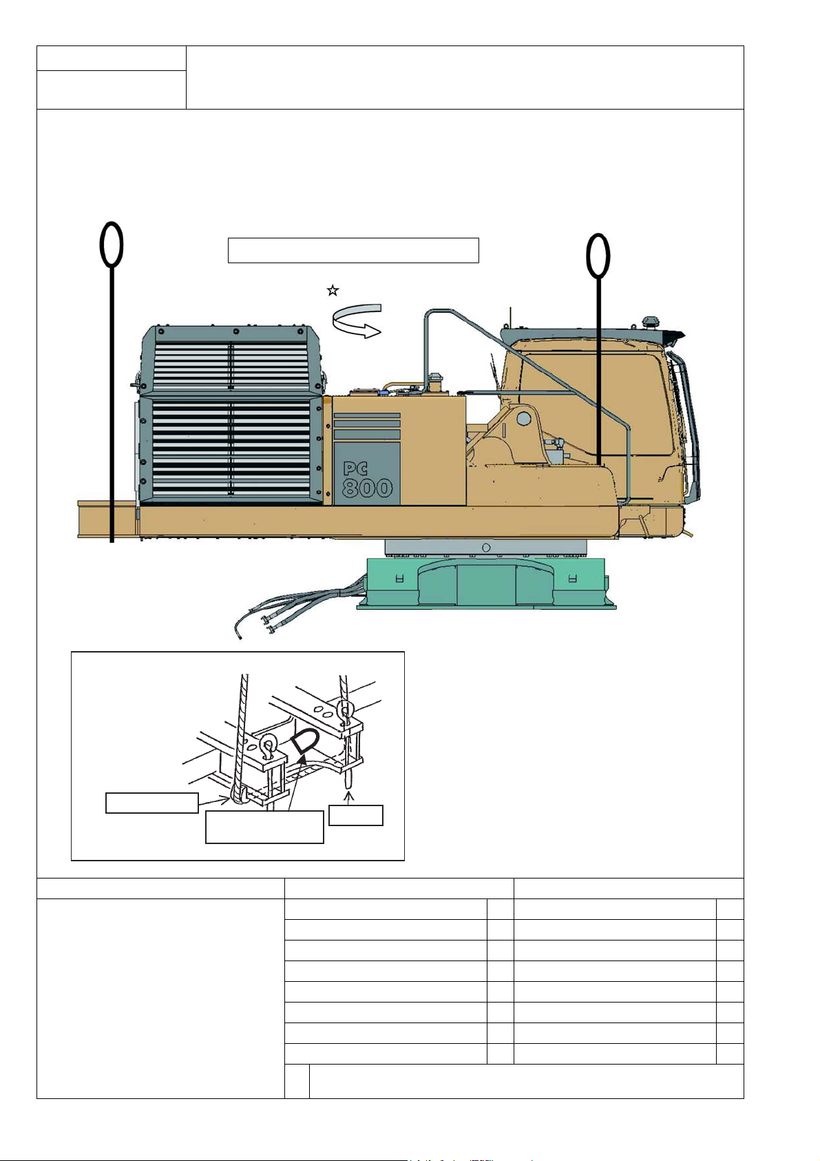
Assembly procedure
Installation of Left and Right Track Frames (1/4)
A-1
• Before transportation, the Upper Structure (also called the “Revolving Frame Assembly”) was rotated 90° from its
original position. Start the engine and return the Upper Structure to its original position by slowly rotating it 90°
as follows.
• Lift the Upper Structure by two cranes and position it on the Track Frames as shown.
Weight of Upper Structure: 25,800 kg
Slowly rotate 90°
Fitting the wire at
counterweight portion
(Example):
Set the wire safely and
securely.
Wooden block
Use a shackle for
secure connection.
Precautions Necessary tools Necessary equipment
Never enter under the lifted Upper Structure.
Stopper
Name Q’ty Name Q’ty
ø 25 × 5000 wire 4 45 ton crane 1
SD30 shackle 1
Others
20
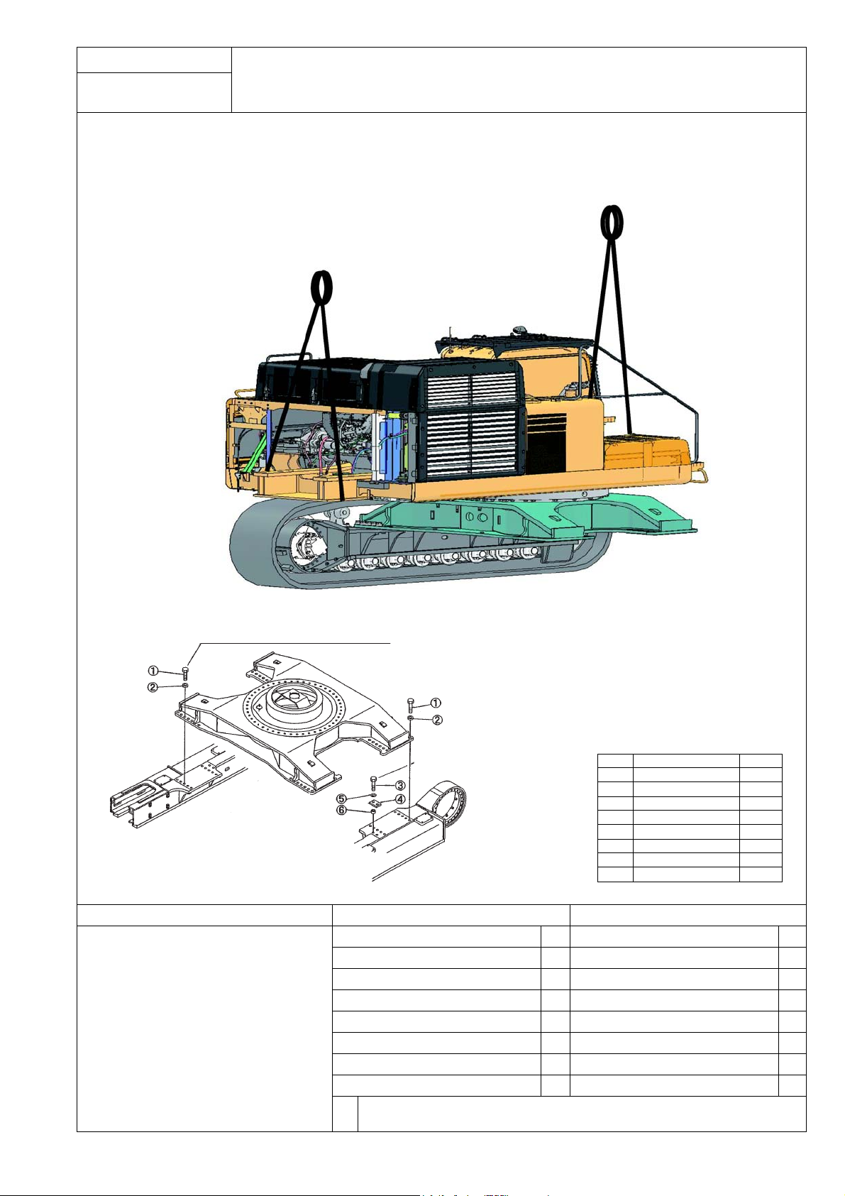
Assembly procedure
Installation of Left and Right Track Frames (2/4)
A-1
• Lower the Upper Structure by two cranes and install it on the Track Frames as shown.
Right track frame
Mount the M36 × 3 bolts and tighten them
with 250 to 310 kgm torque.
Mount the M33 × 3 bolts
and tighten them with
200 to 250 kgm torque.
Left track frame
Precautions Necessary tools Necessary equipment
Name Q’ty Name Q’ty
4 time wrench 1 45 ton crane 2
Torque wrench (100 kg) 1
Socket (25.4 Sq. × 55 mm) 1
Torque wrench (4,200 kg) 1
No. Loose-supply items Q’ty
1 209-09-11310 8
2 209-30-61120 8
3 209-09-51110 8
4 209-30-71121 2
5 01643-33690 8
6 209-30-11330 8
7 209-09-51110 32
8 209-30-61120 32
Others
21
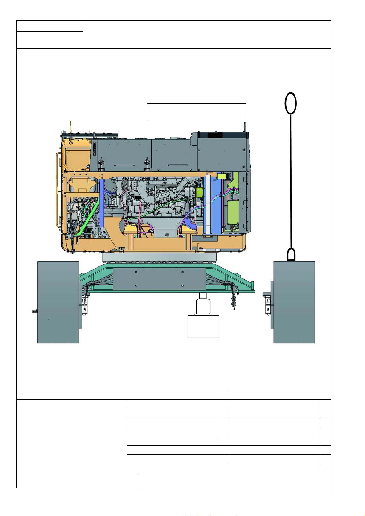
Assembly procedure
Installation of Left and Right Track Frames (3/4)
A-1
• Secure two points of the center frame of the track by placing a hydraulic jack and a 300 × 400 mm wooden block at
each point. Make sure that these points do not interfere with the upper structure rotation.
• Lift the Track Frame Assembly and install it on the Center Frame.
Weight of a single side of Track Frame
Assembly: 11,000 kg
Precautions Necessary tools Necessary equipment
Name Q’ty Name Q’ty
Hydraulic jack (50 ton) 2 45 ton crane 1
Wooden block (300 × 400 mm) 2
Wire (ø30 mm, 5000 mm long) 2
Pin (ø50 mm, 500 mm) 2
Others
22
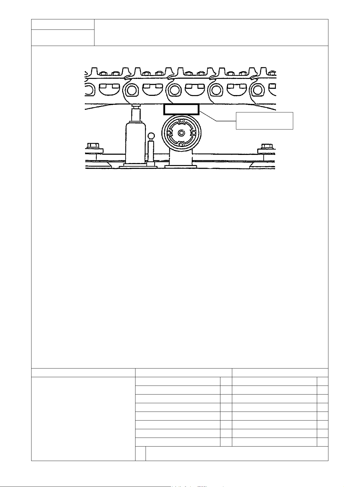
Assembly procedure
Installation of Left and Right Track Frames (4/4)
A-1
Thickness of 100 mm
Wooden block
a When tightening bolts, raise the track with a hydraulic jack as shown above so as to get sufficient space for tightening.
Precautions Necessary tools Necessary equipment
Do not remove the shoes before assembling
(so as to maintain the tightening torques of
the shoe bolts).
Name Q’ty Name Q’ty
4 time wrench 1
Torque wrench (100 kg) 1
Socket (25.4 Sq. × 55 mm) 1
Torque wrench (4,200 kg) 1
Others
23
Assembly procedure
A-2
Installation of Travel Pipe (1/3)
Fig. 1
Fig. 2
L.H. R.H.
No.
Parts already installed to body
1 209-64-12131 2
2 209-64-12141 2
3 209-62-42610 2
4 209-62-42520 1
5 209-62-42510 1
No. Loose-supply items Q’ty
6 07000-13032 4
Q’ty
Precautions Necessary tools Necessary equipment
• Before removing the oil stopper of each
hose, turn the bolt slowly to release the
internal pressure.
Name Q’ty Name Q’ty
Width across flats 32 spanner 2
Width across flats 24 spanner 2
Width across flats 22 spanner 2
KW12P impact 1
L150 extension 1
M17 socket 1
Others
24

Assembly procedure
A-2
Installation of Travel Pipe (2/3)
L.H. R.H.
Fig. 3
No.
Parts already installed to body
1 209-64-12131 2
2 209-64-12141 2
3 209-62-42610 2
4 209-62-42520 1
5 209-62-42510 1
No. Loose-supply items Q’ty
6 07000-13032 4
Precautions Necessary tools Necessary equipment
Name Q’ty Name Q’ty
Q’ty
Others
25
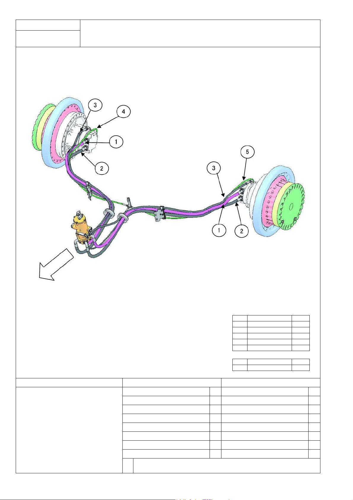
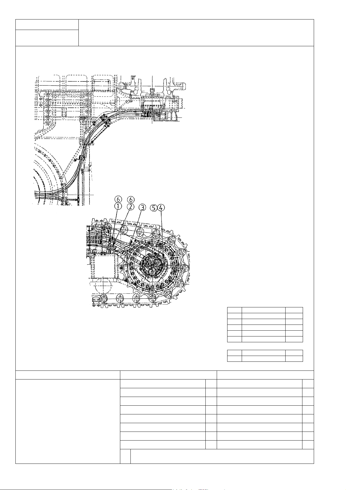
Assembly procedure
Installation of Travel Pipe (3/3)
A-2
(1) Arrange the pilot hoses (4) (L.H.), (5) (R.H.) for selecting machine speed and the drain hoses (3) (Figs 1,2 and 3)
(2) Arrange the main hoses (1) and (2) on the travel motor side (Figs 1,2 and 3). Use new O-rings (6) out of the loose-supply
items and use split flange, bolt and washer out of the travel motor parts.
No.
Parts already installed to body
1 209-64-12131 2
2 209-64-12141 2
3 209-62-42610 2
4 209-62-42520 1
5 209-62-42510 1
No. Loose-supply items Q’ty
6 07000-13032 4
Precautions Necessary tools Necessary equipment
Name Q’ty Name Q’ty
Others
26
Q’ty
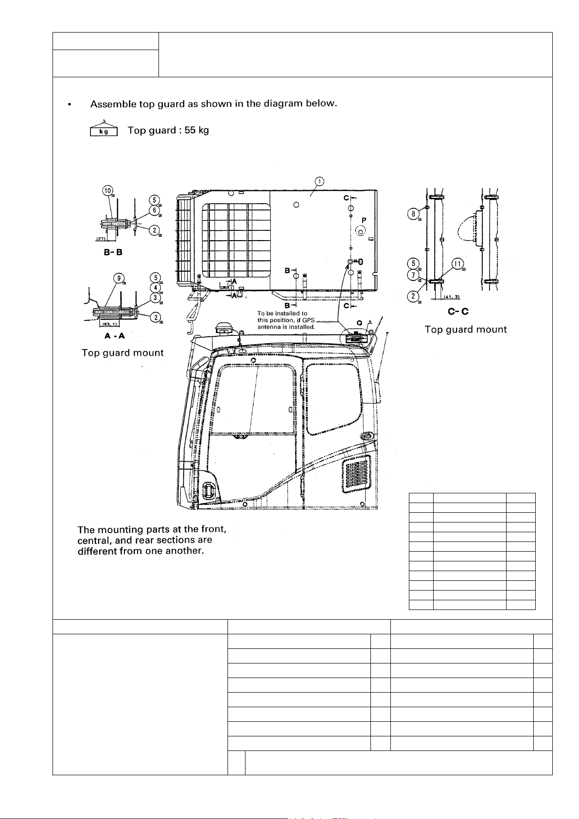
Assembly procedure
A-3
.
Installation of Top Guard
No. Loose-supply items Q’ty
1 209-954-4211 1
2 195-Z11-2970 6
3 01011-81220 2
4 01643-31232 4
5 130-43-64260 6
6 01024-81280 2
7 01024-81295 2
8 01024-01220 2
9 20Y-954-4220 2
10 20Y-954-4240 2
11 20Y-954-4230 2
Precautions Necessary tools Necessary equipment
Name Q’ty Name Q’ty
Others
27
 Loading...