

Komatsu PC600-8, PC600LC-8 Service Manual

UEAM005000
Operation &
Maintenance Manual
PC600-8
PC600LC-8
HYDRAULIC EXCAVATOR
SERIAL NUMBER
PC600-8 - K50001
PC600LC-8 - K50001
WARNING
and up
and up
Unsafe use of this machine may cause serious injury or
death. Operators and maintenance personnel must read
this manual before operating or maintaining this
machine. This manual should be kept inside the cab for
reference and periodically reviewed by all personnel who
will come into contact with the machine.


FOREWORD
11
FOREWORD FOREWORD
FOREWORD 1
This manual provides rules and guidelines which will help you use this machine safely and effectively. The precautions in this manual must be followed at all times when performing operation and maintenance. Mo st accidents
are caused by the failure to follow fundamental safety rules for the operation and maintenance of machi nes. Accidents can be prevented by knowing beforehand conditio ns that may cause a haz ard when performing op eration
and maintenance.
WARNING
Before beginning operation or maintenance, operators and maintenance personnel must always observe
the following points.
q Read this manual thoroughly and understand its contents fully.
q Read the safety messages and safety labels given in this manual carefully so that they should be
understood fully.
q Keep this manual at the storage location for the Operation and Maintenance Manual given below so
that all personnel involved in working on the machine can consult it periodically.
q In case this manual should be lost or damaged, immediately contact Komatsu or your Komatsu dis-
tributor to obtain a new copy.
q When you sell the machine, make sure that this manual should be provided to the new owne r to get her
with the machine.
In this manual, measurements are expressed in internationa l standard units (SI). For the reference purpose, weight units used in the p ast are also displayed in ( ).
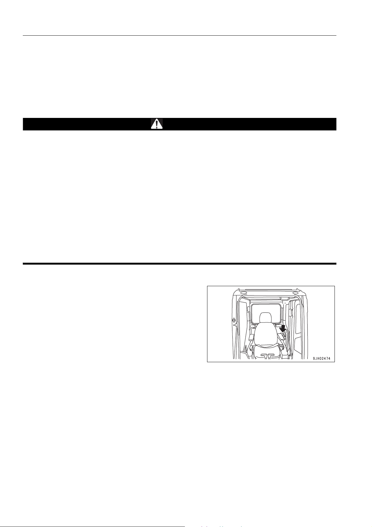
Storage location fo r the Operation and Maintenance Manual:
magazine box on the left side of the operator's seat.
1-2

FOREWORD SAFETY INFORMATION
SAFETY INFORMATION 1
To enable you to use this machine safely, safety precautions and labels are given in this manual and affixed to the
machine to give explanations of situations involving potential hazards and of the methods of avoiding such situations.
Signal words 1
The following signal words are used to inform you that there is a potential hazardous situation that may lead to personal injury or damage.
In this manual and on machine labels, the following signal words are used to express the potential level of hazard.
DANGER
WARNING
CAUTION
Indicates an imminently hazardous situation which, if not avoided, will result in death
or serious injury.
Indicates a potentially hazardous situation which, if not avoided, could result in death
or serious injury.
Indicates a potentially hazardous situation which, if not avoided, may result in minor or
moderate injury. This word is used also to alert against unsafe practices that may
cause property damage.
Example of safety message using signal word 1
WARNING
When standing up from the operator's seat, always place the lock lever in the LOCK position.
If you accidentally touch the control levers when they are n ot locked, this may cau se a serious injury or
death.
Other signal words 1
In addition to the above, the following signal words are used to indicate precaution s that shou ld be followed to protect the machine or to give information that is useful to know.
NOTICE
REMARKS This word is used for information that is useful to know.
This word is used for precautions that must be taken to avoid actions which could shorten
the life of the machine.
1-3
SAFETY INFORMATION FOREWORD
q Safety labels
Safety labels are affixed to the machine to inform the operator or maintenance worker on the spot when carrying
out operation or maintenance of the machine that may involve hazard.
This machine uses “Safety labels using words“ and “Safety labels using pictograms“ to indicate safety pr ocedur es.
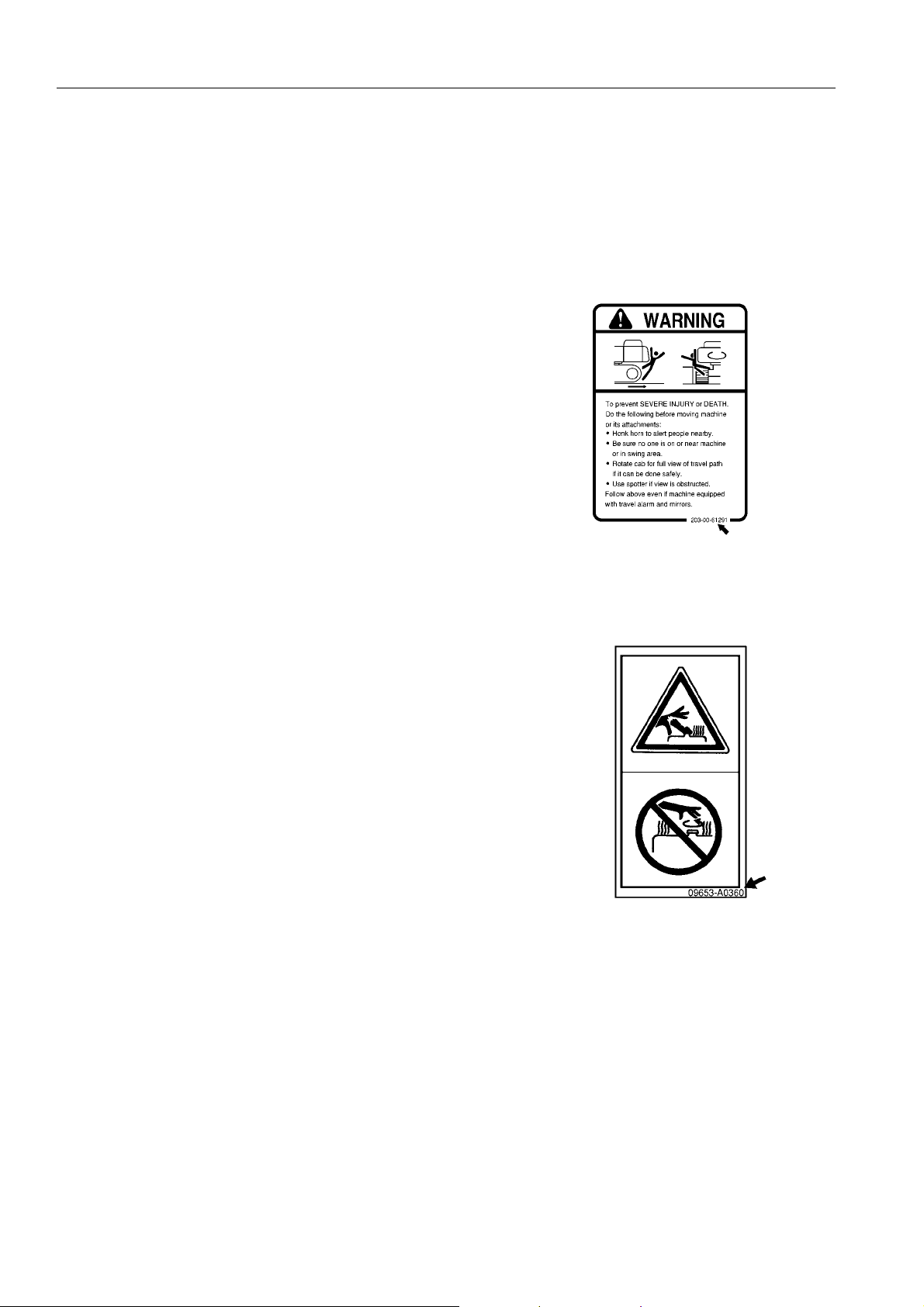
Example of safety label using words 1
Part No.
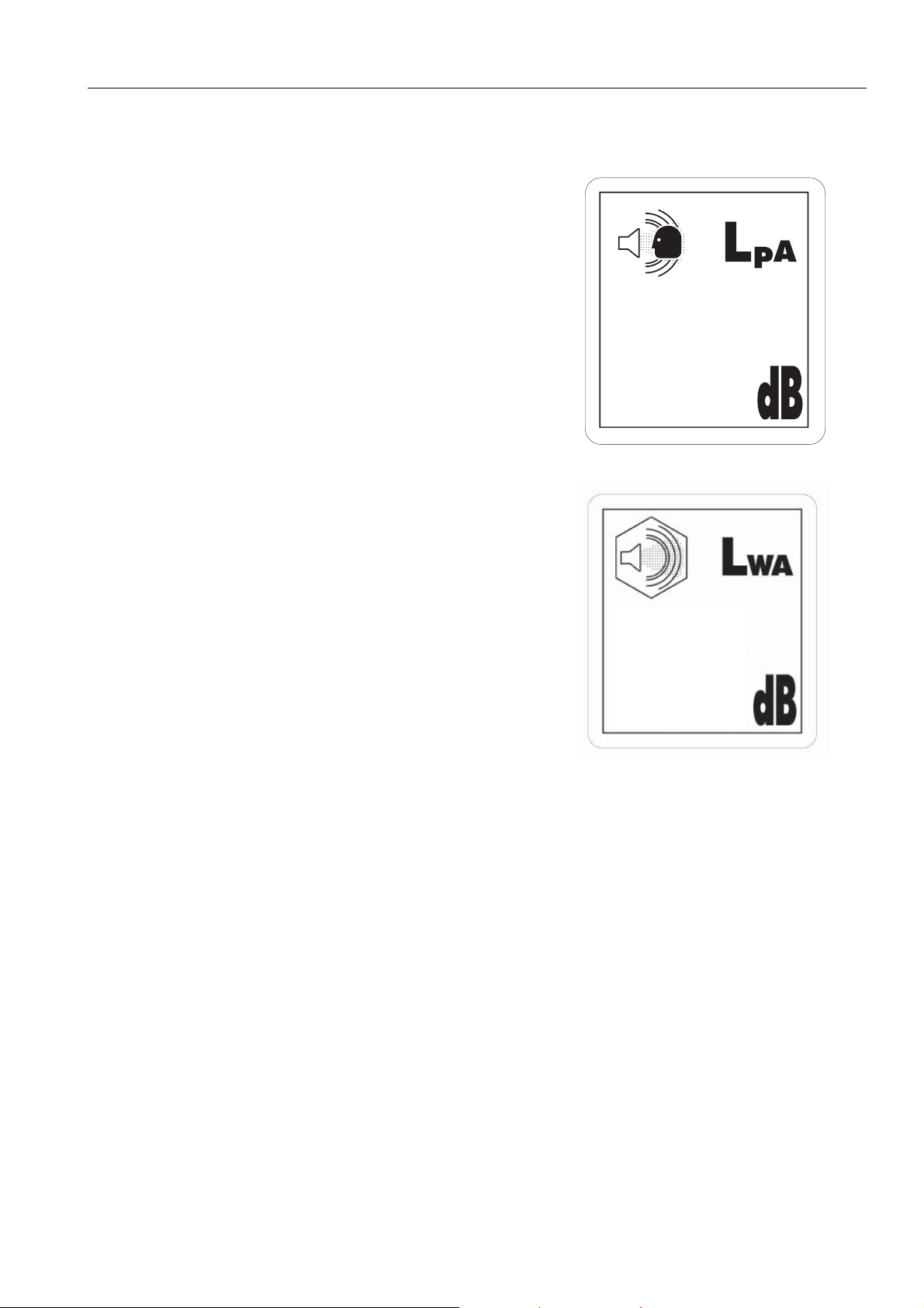
Safety labels using pictogram 1
Safety pictograms use a picture to expre ss a level of hazardous condition equivalent to the signal word. These safety pictograms use pictures in order to let the operator or
maintenance worker understand the level and type of hazardous condition at all times.
Safety pictograms show the type of hazardous condition at the
top or left side, and the method of avoiding the hazardous condition at the bottom or right side. In addition, the type of hazardous condition is displayed inside a triangle and the method
of avoiding the hazardous condition is shown inside a circle.
Part No.
Komatsu cannot predict every circumstance that might involve a potential hazard in operation and maintena nce.
Therefore, the safety messages in this manual and on the machine may not include all po ssible safety precautions.
If any procedures or actions not specifically recommended or allowed in this manual are used, it is your responsibility to take the necessary steps to ensure safety.
In no event should you engage in prohibited uses or actions described in this manual.
The explanations, values, and illustrations in this manual were prepared based on the latest information available
at that time. Continuing improvements in the design of this machine can lead to changes in detail which may not
be reflected in this manual. Consult Komatsu or your Komatsu distributor for the latest available information of
your machine or for questions regarding information in this manual.
The numbers in circles in the illustrations correspond to the numbers in ( ) in the text. (For example: 1 -> (1))
1-4
FOREWORD SAFETY INFORMATION
NOISE 1
q Sound pressure level at the operator’s station, measured
according to ISO6396 (Dynamic test method,simulated
working cycle).
75
q Sound power level emmited. This is the guaranteed value
as specified in the European directive 2000/14/EC
108
1-5

SAFETY INFORMATION FOREWORD
Vibration levels 1
When used for its intended purpose, levels of vibration for the earth-moving machine transmitted from the operator’s seat are lower than or equal to the tested vibrations for the relative machinery class in compliance with ISO
7096.
The actual acceleration value for the hands and arms is less than or equal to 2.5 m/s². The actual acceleration
value for the body is less than or equal to 0.5 m/s².
These values were determined using a representative machine and measured during the typical operating condi-
tion indicated below according to the measurement procedures that are defined in the standards ISO 2631/1 and
ISO 5349.
Operating condition:
Excavating (Digging-loading-rotating-unloading-rotating)
Guide to Reduce Vibration Levels on Machine 1
The following guides can help an operator of this machine to reduce the whole body vibration levels:
1. Use the correct equipment and attachments.
2. Maintain the machine according to this manual
q Tension of crawler (for crawler machines)
q Brake and steering systems
q Controls, hydraulic system and linkages
3. Keep the terrain where the machine is working and traveling in good condition
q Remove any large rocks or obstacles
q Fill any ditches and holes
q Site manager should provide machine operators with machine and schedule time to maintain terrain con-
ditions
4. Use a seat that meets ISO 7096 and keep the seat maintained and adjusted
q Adjust the seat and suspension for the weight and size of the operator
q Wear seat belt
q Inspect and maintain the seat suspension and adjustment mechanisms
5. Steer, brake, accelerate, and move the attachment levers and pedals slowly so that the machine moves
smoothly
6. Adjust the machine speed and travel path to minimize the vibration level
q When pushing with bucket or blade, avoid sudden loading; load gradually
q Drive around obstacles and rough terrain conditions
q Slow down when it is necessary to go over rough terrain
q Make the curve radius of traveling path as large as possible
q Travel at low speed when traveling around sharp curves
1-6

FOREWORD SAFETY INFORMATION
7. Minimize vibrations for long work cycle or long distance traveling
q Reduce speed to prevent bounce
q Transport machines long distances between worksites
8. The following guidelines can be effective to minimize risks of low back pain
q Operate the machine only when you are in good he alt h.
q Provide breaks to reduce long periods of sitting in the same posture
q Do not jump down from the cab or machine
q Do not repeatedly handle and lift loads
1-7
INTRODUCTION FOREWORD
INTRODUCTION 1
This Komatsu machine is designed to be used mainly for the following work:
q Digging work
q Leveling work
q Ditching work
q Loading work
q Demolition work
See the section “RECOMMENDED APPLICATIONS (3-119)“ for further det ails.
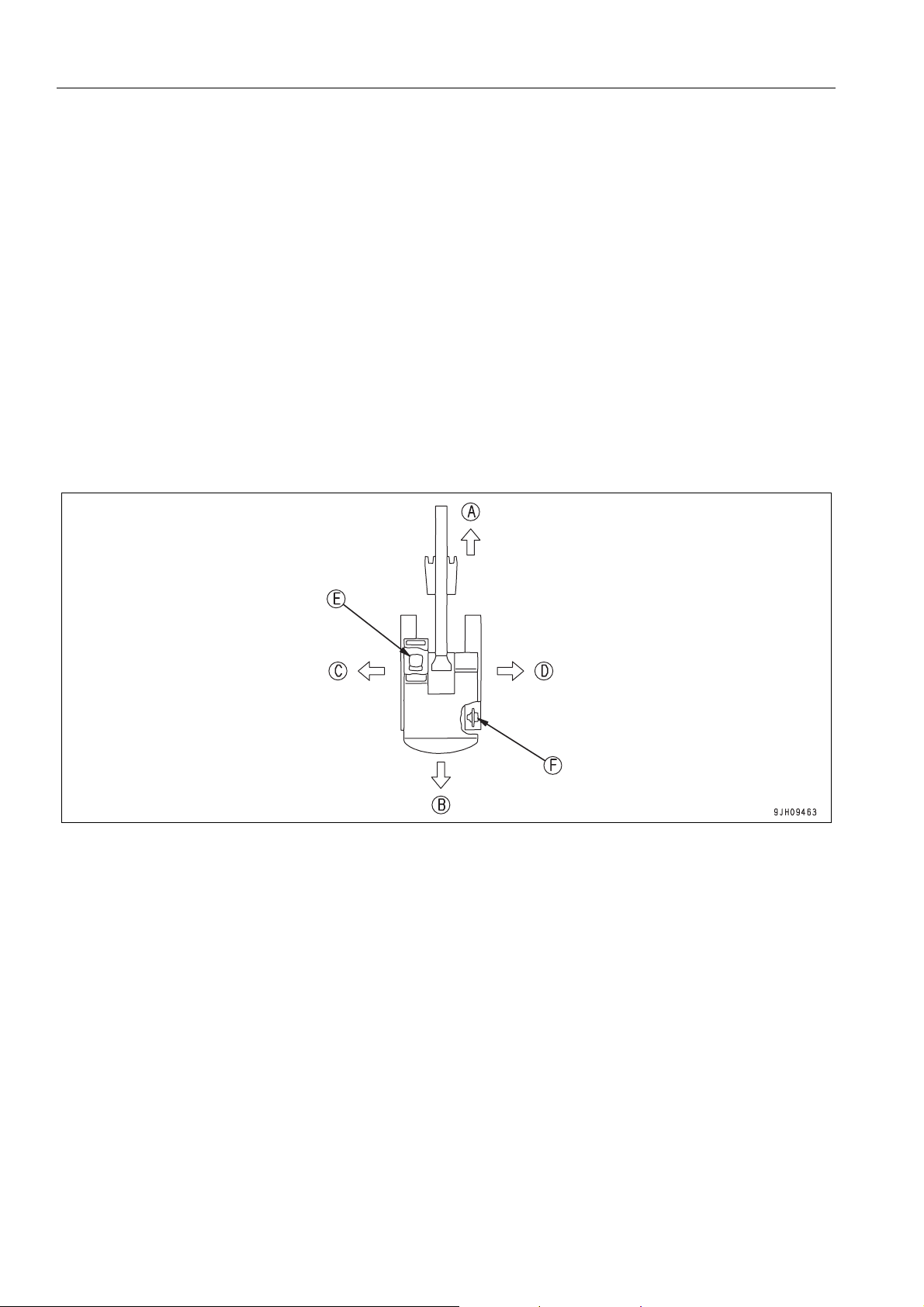
DIRECTIONS OF MACHINE 1
(A) Front (E) Operator's seat
(B) Rear (F) Sprocket
(C) Left
(D) Right
In this manual, the terms front, rear, left, and right refer to the travel direction as seen from the operator's seat
when the operator's seat is facing the front and the sprocket is at the rear of the machine.
1-8
FOREWORD INTRODUCTION
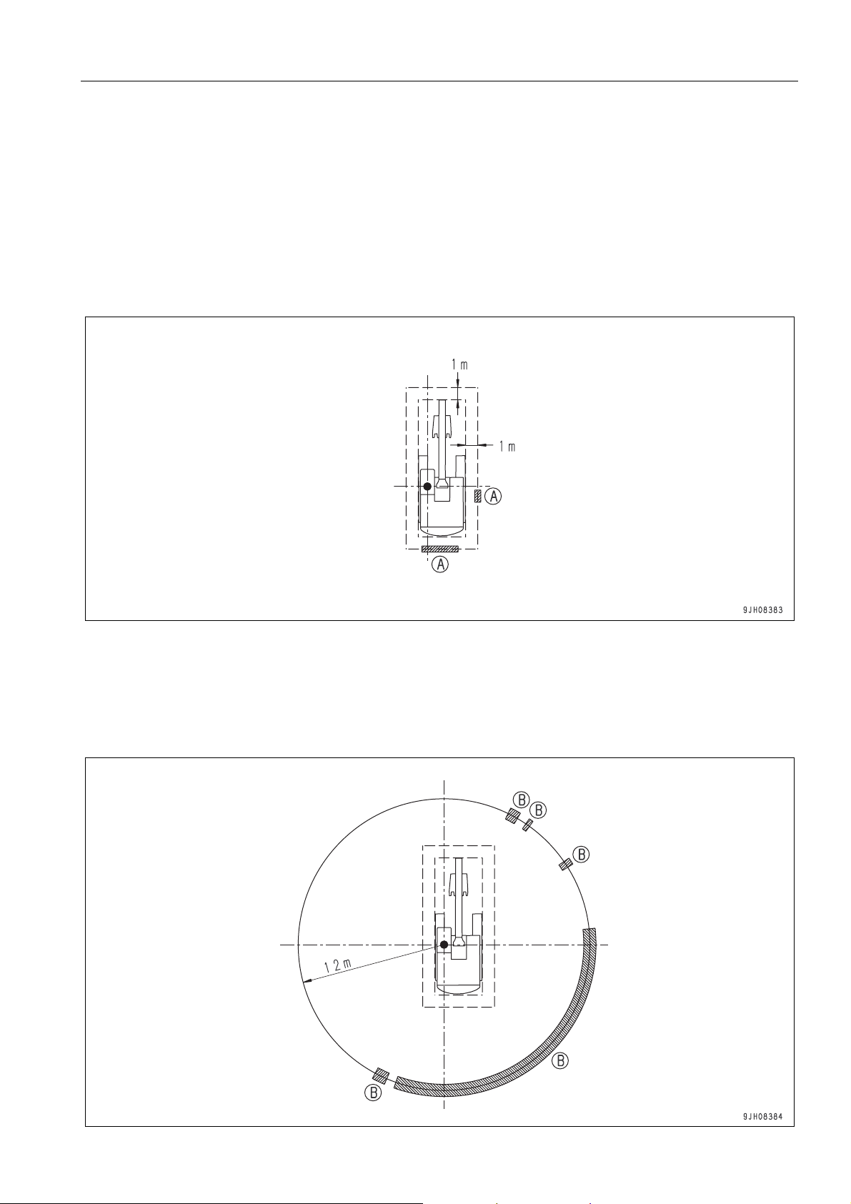
VISIBILITY FROM OPERATOR'S SEAT 1
The visibility standards (ISO 5006) for this machine require a view shown in the diagram below.
PROXIMITY VISIBILITY 1
The visibility of this machine in the area 1 m from the outside surface of the machine at a height of 1.5 m is shown
in the diagram below. The hatched area (A) shows the area where the view is blocked by part of the machine when
mirrors or other aids to visibility are installed as standard. Please be fully aware that there are places that cannot
be seen when operating the machine.
12M CIRCUMFERENCE VISIBILITY 1
The visibility at a radius of 12 m from the machine is as shown in the diagram below. The hatched areas (B) show
the areas where the view is blocked when mirrors or other aids to visibility are installed as standard. Please be
fully aware that there are places that cannot be seen when operating the machine.
1-9

INTRODUCTION FOREWORD
BREAKING-IN THE NEW MACHINE 1
NOTICE
Your Komatsu machine has been thoroughly adjusted and tested before shipment from the factory. However, ope rating the machine under full load before bre aking the machine in can adverse ly affect the perf ormance and shorten the machine life.
Be sure to break in the machine for the initial 100 hours (as indicated on the service meter).
Make sure that you fully understand the content of this manual, and pay careful attention to the following points
when breaking in the machine.
q Run the engine at idle for 15 seconds after starting it. Dur-
ing this time, do not operate the control levers or fuel control dial.
q Idle the engine for 5 minutes after starting it up.
q Avoid operation with heavy loads or at high speeds.
q Immediately after starting the engine, avoid sudden starts,
sudden acceleration, unnecessary sudden stops, and sud
den changes in direction.
-
1-10
FOREWORD PRODUCT INFORMATION
PRODUCT INFORMATION 1
When requesting service or ordering replacement parts, please inform your Komatsu distributor of the following
items.
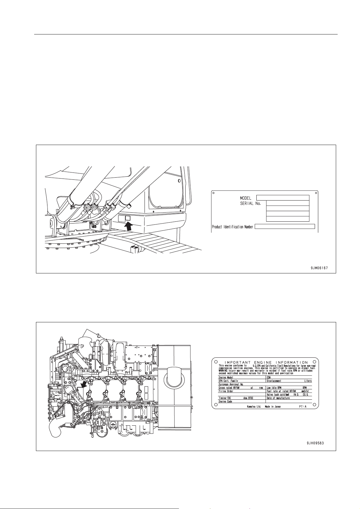
PRODUCT IDENTIFICATION NUMBER (PIN)/MACHINE SERIAL NO. PLATE 1
On the bottom right of the operator's cab
The design of the nameplate differs according to the territory.
ENGINE SERIAL NUMBER PLATE AND ITS LOCATION 1
On the upper side of the engine cylinder head cover.
EPA: Environmental Protection Agency, U.S.A.
1-11

PRODUCT INFORMATION FOREWORD
SERVICE METER LOCATION 1
On top of the machine monitor
YOUR MACHINE SERIAL NUMBERS AND DISTRIBUTOR 1
Machine serial No.
Engine serial No.
Product Identification Number
Manufacturers name:
Address:
Distributor
Address
Phone
KOMATSU UK Ltd.
Durham Road
Birtley
Chester-Le street
County Durham DH3 2QX
United Kingdom
1-12
FOREWORD PRODUCT INFORMATION
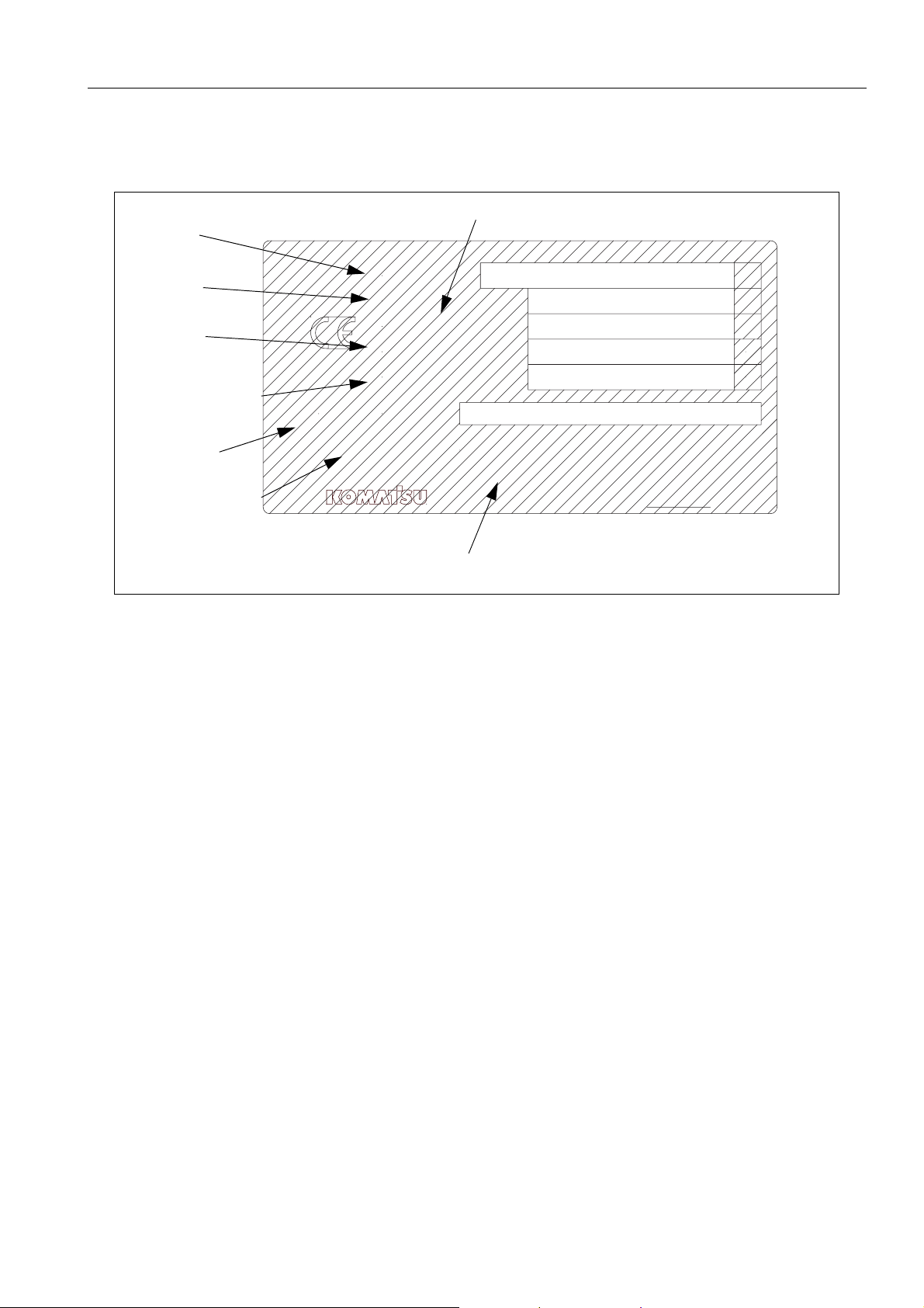
MACHINE SERIAL PLATE 1
MANUFACTURING YEAR
MODEL
SERIAL
WEIGHT
ENGINE POWER
PRODUCT ID
NUMBER
MANUFACTURER
MODEL
SERIAL No.
MANUFACT. YEAR
MASS
ENGINE POWER
Product Identification Number
MANUFACTURER
Manufactured by Komatsu UK Ltd.
for Komatsu Ltd.,Tokyo,Japan
Komatsu UK Ltd, Birtley, Co Durham, United Kingdom
kg
kW
205-00-K1291
1-13

CONTENTS
CONTENTS
FOREWORD
FOREWORD.........................................................................................................................................................1-2
SAFETY INFORMATION......................................................................................................................................1-3
SIGNAL WORDS............................................................................................................................... 1-3
EXAMPLE OF SAFETY MESSAGE USING SIGNAL WORD...........................................................1-3
OTHER SIGNAL WORDS .................................................................................................................1-3
EXAMPLE OF SAFETY LABEL USING WORDS .............................................................................1-4
SAFETY LABELS USING PICTOGRAM...........................................................................................1-4
NOISE......................................................................................................................................................... 1-5
Vibration levels............................................................................................................................................1-6
GUIDE TO REDUCE VIBRATION LEVELS ON MACHINE ................ ..............................................1-6
INTRODUCTION................................................................................................................................................... 1-8
DIRECTIONS OF MACHINE ...................................................................................................................... 1-8
VISIBILITY FROM OPERATOR'S SEAT....................................................................................................1-9
PROXIMITY VISIBILITY ....................................................................................................................1-9
12M CIRCUMFERENCE VISIBILITY ................................................................................................ 1-9
BREAKING-IN THE NEW MACHINE .......................................................................................................1-10
PRODUCT INFORMATION................................................................................................................................1-11
PRODUCT IDENTIFICATION NUMBER (PIN)/MACHINE SERIAL NO. PLATE...................................... 1-11
ENGINE SERIAL NUMBER PLATE AND ITS LOCATION.......................................................................1-11
SERVICE METER LOCATION .................................................................................................................1-12
YOUR MACHINE SERIAL NUMBERS AND DISTRIBUTOR ................................................................... 1-12
MACHINE SERIAL PLATE ....................................................................................................................... 1-13
SAFETY
SAFETY INFORMATION......................................................................................................................................2-2
SAFETY LABELS.................................................................................................................................................2-4
LOCATION OF SAFETY LABELS..............................................................................................................2-5
SAFETY LABELS ............................... ... ... ... .... ... ... ....................................... ... ........................................... 2-6
SAFETY INFORMATION....................................................................................................................................2-13
SAFETY MACHINE OPERATION...................................................................................................................... 2-22
STARTING ENGINE................................................................................................................................. 2-22
OPERATION.............................................................................................................................................2-24
TRANSPORTATION................................................................................................................................. 2-30
BATTERY .................................................................................................................................................2-31
TOWING ................................................................................................................................................... 2-32
LIFTING OBJECTS WITH BUCKET......................................................................................................... 2-33
1-14

CONTENTS
SAFETY MAINTENANCE INFORMATION........................................................................................................ 2-34
OPERATION
MACHINE VIEW ILLUSTRATIONS ..................................................................................................................... 3-2
OVERALL MACHINE VIEW........................................................................................................................ 3-2
CONTROLS AND GAUGES....................................................................................................................... 3-3
DETAILED CONTROLS AND GAUGES.............................................................................................................. 3-5
MONITORING SYSTEM............................................................................................................................. 3-5
BASIC OPERATION OF MACHINE MONITOR ........................ ... ... ... ... .... ... ... ... .... ... ... ..................... 3-6
EMERGENCY MONITORS............................................................................................................... 3-9
CAUTION MONITORS....................................................................................................................3-11
BASIC CHECK MONITORS.................................................................. .... ... ... ... .... ... ......................3-13
METER DISPLAY PORTION....................... .... ... ... ... .... ... ... ....................................... ... ... ... .... ... ... ...3-15
MONITOR SWITCHES PORTION .................................................................................................. 3-20
SWITCHES............................................................................................................................................... 3-34
CONTROL LEVERS AND PEDALS ......................................................................................................... 3-41
SUN ROOF............................................................................................................................................... 3-44
OPENING........................................................................................................................................ 3-44
CLOSING......................................................................................................................................... 3-44
WINDSHIELD ........................................................................................................................................... 3-45
EMERGENCY EXIT FROM OPERATOR'S CAB ..................................................................................... 3-50
DOOR LOCK ............................................................................................................................................ 3-50
CAP WITH LOCK...................................................................................................................................... 3-51
HOT AND COOL BOX.............................................................................................................................. 3-52
MAGAZINE BOX....................................................................................................................................... 3-52
ASHTRAY................................................................................................................................................. 3-52
AIR CONDITIONER CONTROLS............................................................................................................. 3-53
AIR CONDITIONER CONTROL PANEL ......................................................................................... 3-53
METHOD OF OPERATION.............................................................................................................3-57
USE AIR CONDITIONER WITH CARE........................................................................................... 3-63
INSPECTION AND MAINTENANCE OF AIR CONDITIONER EQUIPPED MACHINE............. ...... 3-63
OTHER FUNCTIONS.................................. .... ...................................... .... ... ... ... ............................. 3-64
CAB RADIO.............................................................................................................................................. 3-65
USE RADIO WITH CARE................................................................................................................ 3-65
AUXILIARY ELECTRIC POWER.......................... ....................................... ... .... ... ... ... .... ... ... ... ... .... ......... 3-66
24V POWER SOURCE ................................................................................................................... 3-66
12V POWER SOURCE ................................................................................................................... 3-66
FUSE ........................................................................................................................................................ 3-67
CIRCUIT BREAKER................................................................................................................................. 3-68
CONTROLLER ......................................................................................................................................... 3-69
TOOL BOX................................................................................................................................................ 3-69
GREASE PUMP........................................................................................................................................ 3-70
METHOD OF USE........................................................................................................................... 3-70
PRECAUTIONS WHEN USING ...................................................................................................... 3-71
SUPPLYING GREASE.................................................................................................................... 3-71
1-15

CONTENTS
ACCUMULATOR ...................................................................................................................................... 3-73
RELEASING HYDRAULIC PRESSURE WITH ACCUMULATOR................................................... 3-73
MACHINE OPERATIONS AND CONTROLS.....................................................................................................3-74
BEFORE STARTING ENGINE .............. ... ... ....................................... ... .... ... ... ... ... .... ............................... 3-74
WALK-AROUND CHECKS..............................................................................................................3-74
CHECKS BEFORE STARTING....................................................................................................... 3-75
ADJUSTMENT.................................................................................................................................3-84
SEAT BELT .....................................................................................................................................3-87
OPERATIONS BEFORE STARTING ENGINE ............................................................................... 3-88
STARTING ENGINE................................................................................................................................. 3-91
AFTER STARTING ENGINE .................... ... .... ...................................... .... ... ... ... ... .... ... ... ... .... ... ...............3-94
WARMING UP ENGINE .................. ... .... ... ... ... ....................................... ... ... .... ... ... ... .... ..................3-94
WARMING UP HYDRAULIC EQUIPMENT..................................................................................... 3-96
OPERATION AFTER COMPLETION OF WARMING-UP OPERATION.......................................3-100
STOPPING THE ENGINE ............................... ... ... ....................................... ... ... ... .... .............................3-101
MACHINE OPERATION ......................................................................................................................... 3-102
PREPARATIONS FOR MOVING THE MACHINE......................................................................... 3-102
MOVING MACHINE FORWARD..................................... .... ...................................... .... ... ... ... ... .... 3-103
MOVING MACHINE BACKWARD.................................................................... ... ... ... ....................3-104
STOPPING MACHINE................................................................................................................... 3-105
STEERING THE MACHINE.................................................................................................................... 3-106
STEERING .................................................................................................................................... 3-106
SWINGING ............................................................................................................................................. 3-108
WORK EQUIPMENT CONTROLS AND OPERATIONS ........................................................................3-109
WORKING MODE...................................................................................................................................3-110
PROHIBITED OPERATIONS .................................................................................................................3-112
GENERAL OPERATION INFORMATION .............................................................................................. 3-114
TRAVELING ON SLOPES...................................................................................................................... 3-116
ESCAPE FROM MUD............................................................................................................................. 3-118
TRACK ON ONE SIDE STUCK..................................................................................................... 3-118
TRACKS ON BOTH SIDES STUCK....... ... ... ... ... .... ... ... .......................................... ....................... 3-118
RECOMMENDED APPLICATIONS........................................................................................................3-119
DITCHING WORK ......................................................................................................................... 3-119
LOADING WORK ................................... ... ... ... ... .... ... ... ....................................... ... ... .... ... .............3-119
BUCKET REPLACEMENT ..................................................................................................................... 3-120
REPLACEMENT............................................................................................................................ 3-120
PARKING MACHINE ............. ...................................... .... ... ....................................... ... ..........................3-122
MACHINE INSPECTION AFTER DAILY WORK....................................................................................3-123
LOCKING................................................................................................................................................3-124
OVERLOAD WARNING DEVICE (option)..............................................................................................3-124
TRANSPORTATION......................................................................................................................................... 3-125
PRECAUTIONS FOR TRANSPORTATION ........................................................................................... 3-125
LIFTING MACHINE.................................................................................................................................3-125
SHIPPING MACHINE INFORMATION...................................................................................................3-127
TRANSPORTATION POSTURE ............................................................................................................ 3-128
PROCEDURE FOR INCREASING OR REDUCING TRACK FRAME GAUGE...................................... 3-133
1-16

CONTENTS
COLD WEATHER OPERATION...................................................................................................................... 3-135
COLD WEATHER OPERATION INFORMATION................................................................................... 3-135
FUEL AND LUBRICANTS .............................................................................................................3-135
COOLING SYSTEM COOLANT.................................................................................................... 3-135
BATTERY...................................................................................................................................... 3-136
MONITOR...................................................................................................................................... 3-137
AFTER DAILY WORK COMPLETION.................................................................................................... 3-138
AFTER COLD WEATHER SEASON......................................................................................................3-138
LONG TERM STORAGE.................................................................................................................................. 3-139
BEFORE STORAGE............................................................................................................................... 3-139
DURING STORAGE............................................................................................................................... 3-139
AFTER STORAGE.................................................................................................................................. 3-140
STARTING MACHINE AFTER LONG-TERM STORAGE ...................................................................... 3-140
TROUBLES AND ACTIONS ............................................................................................................................ 3-141
RUNNING OUT OF FUEL ....... .... ... ... ... .... ... ....................................... ... ... ... ... ........................................ 3-141
PHENOMENA THAT ARE NOT FAILURES........................................................................................... 3-142
TOWING THE MACHINE ....................................................................................................................... 3-143
SEVERE JOB CONDITION.................................................................................................................... 3-143
DISCHARGED BATTERY ...................................................................................................................... 3-144
BATTERY REMOVAL AND INSTALLATION ................................................................................ 3-144
BATTERY CHARGES ................................................................................................................... 3-145
STARTING ENGINE WITH BOOSTER CABLES.......................................................................... 3-146
OTHER TROUBLE ................................................................................................................................. 3-148
ELECTRICAL SYSTEM................................................................................................................. 3-148
CHASSIS....................................................................................................................................... 3-149
ENGINE......................................................................................................................................... 3-150
ELECTRONIC CONTROL SYSTEM............................................................................................. 3-152
POINT OF CONTACT TO TELEPHONE WHEN ERROR OCCURS............................................ 3-153
MAINTENANCE
MAINTENANCE INFORMATION......................................................................................................................... 4-2
OUTLINE OF SERVICE........................................................................................................................................ 4-4
HANDLING OIL, FUEL, COOLANT, AND PERFORMING OIL CLINIC ... ... ... .... ... ... .................................. 4-4
OIL..................................................................................................................................................... 4-4
FUEL.................................................................................................................................................. 4-4
COOLING SYSTEM COOLANT........................................................................................................ 4-5
GREASE............................................................................................................................................ 4-5
CARRYING OUT KOWA (KOMATSU OIL WEAR ANALYSIS)......................................................... 4-6
OIL AND FUEL STORAGE................................................................................................................ 4-7
FILTERS............................................................................................................................................ 4-7
ELECTRIC SYSTEM MAINTENANCE....................................................................................................... 4-8
WEAR PARTS...................................................................................................................................................... 4-9
WEAR PARTS LIST.................................................................................................................................... 4-9
1-17

CONTENTS
LUBRICANTS, FUEL AND COOLANT SPECIFICATIONS............................................................................... 4-10
RECOMMENDED BRANDS, RECOMMENDED QUALITY FOR PRODUCTS OTHER THAN KOMATSU
GENUINE OIL.............................................. .... ... ... ... ....................................... ... ... .... ...............................4-11
TIGHTENING TORQUE SPECIFICATIONS ......................................................................................................4-12
TIGHTENING TORQUE LIST................................................................................................................... 4-12
SAFETY CRITICAL PARTS...............................................................................................................................4-13
SAFETY CRITICAL PARTS LIST............................................. ....................................... ... .... ... ... ... ......... 4-14
MAINTENANCE SCHEDULE.............................................................................................................................4-15
MAINTENANCE SCHEDULE CHART......................................................................................................4-15
MAINTENANCE INTERVAL FOR HYDRAULIC BREAKER..................................................................... 4-17
MAINTENANCE PROCEDURE.......................................................................................................................... 4-18
INITIAL 100 HOURS MAINTENANCE (ONLY AFTER THE FIRST 100 HOURS) ...................................4-18
INITIAL 500 HOURS MAINTENANCE (ONLY AFTER THE FIRST 500 HOURS) ...................................4-18
WHEN REQUIRED................................................ ....................................... ... ... ... .... ...............................4-19
CHECK, CLEAN AND REPLACE AIR CLEANER ELEMENT......................................................... 4-19
CLEAN INSIDE OF COOLING SYSTEM ........................................................................................ 4-24
CHECK AND TIGHTEN TRACK SHOE BOLTS..............................................................................4-27
CHECK AND ADJUST TRACK TENSION....................................................................................... 4-28
REPLACE BUCKET TEETH (HORIZONTAL PIN TYPE)................................................................4-30
ADJUST BUCKET CLEARANCE .............. ... ... ... .... ... ... ... .... ... ... ... .......................................... .........4-31
CHECK WINDOW WASHER FLUID LEVEL, ADD FLUID..............................................................4-32
CHECK AND MAINTENANCE AIR CONDITIONER ....................................................................... 4-33
CLEAN LINE FILTER, REMOVE DIRT ........................................................................................... 4-34
REPLACE BREAKER CIRCUIT ADDITIONAL OIL FILTER ELEMENT..........................................4-35
CLEAN PILOT LINE FILTER, REMOVE DIRT ................................................................................4-36
BLEEDING AIR FROM HYDRAULIC SYSTEM...............................................................................4-37
CHECK BEFORE STARTING ......................................... ... ....................................... ... ... ... .... ... ... ... ......... 4-40
EVERY 10 HOURS MAINTENANCE........................................................................................................4-41
LUBRICATING.................................................................................................................................4-41
EVERY 100 HOURS MAINTENANCE...................................................................................................... 4-44
LUBRICATING SWING CIRCLE ..................................................................................................... 4-44
EVERY 250 HOURS MAINTENANCE...................................................................................................... 4-45
CHECK OIL LEVEL IN FINAL DRIVE CASE, ADD OIL .................................................................. 4-45
CHECK LEVEL OF BATTERY ELECTROLYTE .............................................................................4-46
CHECK AND TIGHTEN TRACK FRAME AND AXLE CONNECTING BOLTS ............................... 4-48
CHECK ALTERNATOR DRIVE BELT TENSION, ADJUST................................... ... .... ... ... ... ... .... .. 4-49
CHECK AIR CONDITIONER COMPRESSOR BELT TENSION, ADJUST..................................... 4-50
EVERY 500 HOURS MAINTENANCE...................................................................................................... 4-51
REPLACE FUEL PRE-FILTER CARTRIDGE..................................................................................4-51
CHECK SWING PINION GREASE LEVEL, ADD GREASE............................................................4-54
CLEAN,CHECK RADIATOR FINS,OIL COOLER FINS,FUEL COOLER FINS,AFTERCOOLER
FINS,CONDENSER FINS (MACHINES EQUIPPED WITH AIR CONDITIONER),PTO OIL COOLER
FINS.................................................................................................................................................4-55
CLEAN FRESH/RECIRC AIR FILTERS OF AIR CONDITIONER (ONLY FOR MACHINES EQUIPPED
WITH AIR CONDITIONER) ................ ....................................... ... .... ... ... ... ... ...................................4-57
1-18

CONTENTS
CLEAN STRAINER OF P.T.O LUBRICATING OIL FILTER............................................................ 4-58
CHANGE OIL IN ENGINE OIL PAN, REPLACE ENGINE OIL FILTER CARTRIDGE....................4-59
EVERY 1000 HOURS MAINTENANCE....................................................................................................4-61
REPLACE FUEL MAIN FILTER CARTRIDGE ................................................................................ 4-61
REPLACE HYDRAULIC OIL FILTER ELEMENT............................................................................ 4-64
CHANGE OIL IN SWING MACHINERY CASE ............................................................................... 4-65
CHANGE OIL IN P.T.O CASE......................................................................................................... 4-66
CHECK ALL TIGHTENING POINTS OF ENGINE EXHAUST PIPE CLAMPS ............................... 4-67
REPLACE CORROSION RESISTOR CARTRIDGE ....................................................................... 4-67
CHECK WELDED STRUCTURE..................... ... ... ... .... ... ... ... .... ... ... ... ... .... ... ... ... .... ... ... ... ... .... ... ... ... 4-68
REPLACE HYDRAULIC TANK ADDITIONAL BREATHER ELEMENT .......................................... 4-71
CHECK NITROGEN GAS CHARGE PRESSURE IN ACCUMULATOR (FOR BREAKER)............ 4-71
REPLACE BREATHER ELEMENT IN HYDRAULIC TANK ...................................................... ... ... 4-72
EVERY 2000 HOURS MAINTENANCE....................................................................................................4-73
CHANGE OIL IN FINAL DRIVE CASE............................................................................................ 4-73
CLEAN HYDRAULIC TANK STRAINER ......................................................................................... 4-74
CHECKING CHARGE PRESSURE OF NITROGEN GAS IN ACCUMULATOR (FOR CONTROL
CIRCUIT)......................................................................................................................................... 4-75
CHECK ALTERNATOR, STARTING MOTOR ................................................ ... .... ... ... ... ... .... ... ... ... 4-78
EVERY 4000 HOURS MAINTENANCE....................................................................................................4-79
CHECK WATER PUMP................................... ... ....................................... ... ... ... .... ... ... ... ... .... ... ...... 4-79
REPLACE ACCUMULATOR (FOR CONTROL CIRCUIT).............................................................. 4-79
CHECK FOR LOOSENESS OF HIGH-PRESSURE PIPING CLAMP,
HARDENING OF RUBBER .............................................................................................................4-79
CHECK FOR MISSING FUEL SPRAY PREVENTION CAP, HARDENING OF RUBBER.............. 4-81
CHECK OPERATING CONDITION OF COMPRESSOR................................................................ 4-81
EVERY 5000 HOURS MAINTENANCE....................................................................................................4-82
CHANGE OIL IN HYDRAULIC TANK.............................................................................................. 4-82
EVERY 8000 HOURS MAINTENANCE....................................................................................................4-83
REPLACE HIGH-PRESSURE PIPING CLAMP .............................................................................. 4-83
REPLACE FUEL SPRAY PREVENTION CAP................................................................................ 4-83
SPECIFICATIONS
SPECIFICATIONS................................................................................................................................................ 5-2
1-19

CONTENTS
ATTACHMENTS AND OPTIONS
GENERAL PRECAUTIONS FOR SAFETY..........................................................................................................6-2
PRECAUTIONS WHEN SELECTING.........................................................................................................6-2
READ THE INSTRUCTION MANUAL THOROUGHLY.............................................................................. 6-2
PRECAUTIONS WHEN REMOVING OR INSTALLING............................................................................. 6-2
PRECAUTIONS WHEN USING..................................................................................................................6-3
ATTACHMENT GUIDE.........................................................................................................................................6-4
COMBINATIONS OF WORK EQUIPMENT................................................................................................6-4
WORKING RANGE DIAGRAM..........................................................................................................6-5
TRACK SHOES SELECTION..................................................................................................................... 6-6
HANDLING MACHINES EQUIPPED WITH KOMTRAX............................................................................. 6-7
BASIC PRECAUTIONS.....................................................................................................................6-7
INDEX
COLOPHON
1-20

SAFETY
12
WARNING
Please read and make sure that you fully understand the precautions discribed in this manual and the safety labels on
the machine. When operating or servicing the machine,
always follow these precaustions strictly.

SAFETY INFORMATION SAFETY
SAFETY INFORMATION 2
SAFETY LABELS................................................................................................................................................ 2-42
LOCATION OF SAFETY LABELS.................................. ....................................... ... .... ... ... ... .... ..................2-52
SAFETY LABELS.........................................................................................................................................2-62
SAFETY INFORMATION
Safety rules................................................................................................................................................ 2-132
If problems are found.................................................................................................................................2-132
Working wear and personal protective items.............................................................................................2-132
Fire extinguisher and first aid kit ................................................................................................................ 2-132
Safety equipment.......................................................................................................................................2-142
Keep machine clean................................................................................................................................... 2-142
Keep operator's compartment clean .......................................................................................................... 2-142
Leaving operator's seat with lock............................................................................................................... 2-142
Handrails and steps ..................... ... ... .... ... ... ... .... ...................................... .... ... ... ... ... .... ... ..........................2-152
Mounting and dismounting.........................................................................................................................2-162
No persons on attachments.......................................................................................................................2-162
Do not get caught in articulated portion ........................................... ...................................... ....................2-162
Burn prevention..........................................................................................................................................2-162
Fire prevention and explosion prevention..................................................................................................2-172
Action if fire occurs.....................................................................................................................................2-182
Windshield washer fluid ..................... ....................................... ... .... ... ... ... .... ... ... ... ... .... ... ..........................2-182
Falling objects, flying objects and intruding objects prevention .................................................................2-182
Attachment installation. ... ... ... .... ... ... ... .... ... ... ... .... ...................................... .... ... ... ... ... .... ... ..........................2-182
Attachment combinations.................................... ... ....................................... ... ... ... ... .... ... ... .......................2-182
Cab window glasses ....................... ... .... ... ... ... .... ... ... ....................................... ... ... ... .... ... ..........................2-192
Unauthorized modifications ........................................................................................................................ 2-192
Safety at jobsite..........................................................................................................................................2-192
Working on loose ground........................................................................................................................... 2-192
Distance to high voltage cables .................................................................................................................2-202
Ensure good visibility .................................................................................................................................2-202
Ventilation for enclosed area......................................................................................................................2-212
Signalman's signal and signs.......................... .... ... ... ... ... .... ... ... ... .... ... ... ... .... ............................................. 2-212
Emergency exit from operator's cab .......................................................................................................... 2-212
Asbestos dust hazard prevention...............................................................................................................2-212
2-2

SAFETY SAFETY INFORMATION
SAFETY MACHINE OPERATION .................................................................................................................... 2-222
STARTING ENGINE.................................................................................................................................. 2-222
Checks before starting engine............................................................................................................ 2-222
Safety rules for starting engine........................................................................................................... 2-232
Starting engine in cold weather........................................................................................................... 2-232
OPERATION.............................................................................................................................................. 2-242
Checks before operation..................................................................................................................... 2-242
Safety rules for changing machine directions..................................................................................... 2-242
Safety rules for traveling..................................................................................................................... 2-252
Traveling on slopes............................................................................................................................. 2-252
Operations on slopes..........................................................................................................................2-262
Prohibited operations.......................................................................................................................... 2-262
Operations on snow............................................................................................................................ 2-282
Parking machine................................................................................................................................. 2-292
TRANSPORTATION.................................................................................................................................. 2-302
Loading and unloading ....................................................................................................................... 2-302
Shipping the machine ......................................................................................................................... 2-302
BATTERY .................................................................................................................................................. 2-312
Battery hazard prevention................................................................................................................... 2-312
Starting engine with booster cables.................................................................................................... 2-322
TOWING ....................................................................................................................................................2-322
Safety rules for towing ........................................................................................................................ 2-322
LIFTING OBJECTS WITH BUCKET.......................................................................................................... 2-332
Safety rules for lifting objects.............................................................................................................. 2-332
SAFETY MAINTENANCE INFORMATION....................................................................................................... 2-342
Warning Tag .............................................................................................................................................. 2-342
Keep Work Place Clean and Tidy... ... ... ... .......................................... ........................................................ 2-342
Appoint Leader when Working with Others.................. ... ... ... .... ... ... ... .... ... ................................................. 2-342
Stop Engine Before Carrying Out Maintenance......................................................................................... 2-352
Two Workers for Maintenance when Engine is Running ........................................................................... 2-352
Proper Tools ............ ... ....................................... ... ... .... ... ....................................... ... ... .
Accumulator............................................................................................................................................... 2-362
Personnel................................................................................................................................................... 2-362
Attachments............................................................................................................................................... 2-372
Work Under the Machine ........................................................................................................................... 2-372
Noise.......................................................................................................................................................... 2-372
When Using Hammer................................................................................................................................. 2-372
Welding Works............................ .... ... ....................................... ... ... ... .... .................................................... 2-372
Removing Battery Terminals................. ... .... ... ... ... ....................................... ... ... .... ... ... ... .... ... .................... 2-382
Safety First when Using High-pressure Grease to Adjust Track Tension..................................................2-382
Do Not Disassemble Recoil Springs.......................................................................................................... 2-382
Safety Rules for High-pressure Oil ............................................................................................................ 2-382
Precaution for High Fuel Pressure............................... ... ... ... .... ... ... ........................................................... 2-392
Safety Handling High-pressure Hoses....................................................................................................... 2-392
Precaution for High Voltage...................................................................... ... .............................................. 2-392
Waste Materials ......................................................................................................................................... 2-402
Air Conditioner Maintenance...................................................................................................................... 2-402
Compressed Air......................................................................................................................................... 2-402
Periodic Replacement of Safety Critical Parts ........................................................................................... 2-402
............................. 2-362
2-3

SAFETY LABELS SAFETY
SAFETY LABELS 2
The following warning signs and safety labels are used on this machine.
q Be sure that you fully understand the correct position and content of labels.
q To ensure that the content of labels can be read properly, be sure that they are in the correct place and always
keep them clean. When cleaning them, do not use organic solvents or gasoline. These may cause the labels
to peel off.
q There are also other labels in addition to the warning signs and safety labels. Handle those labels in the same
way.
q If the labels are damaged, lost, or cannot be read properly, replace them with new ones. For details of the p art
numbers for the labels, see this manual or the actual label, and place an order with Komatsu distributor.
2-4
SAFETY SAFETY LABELS
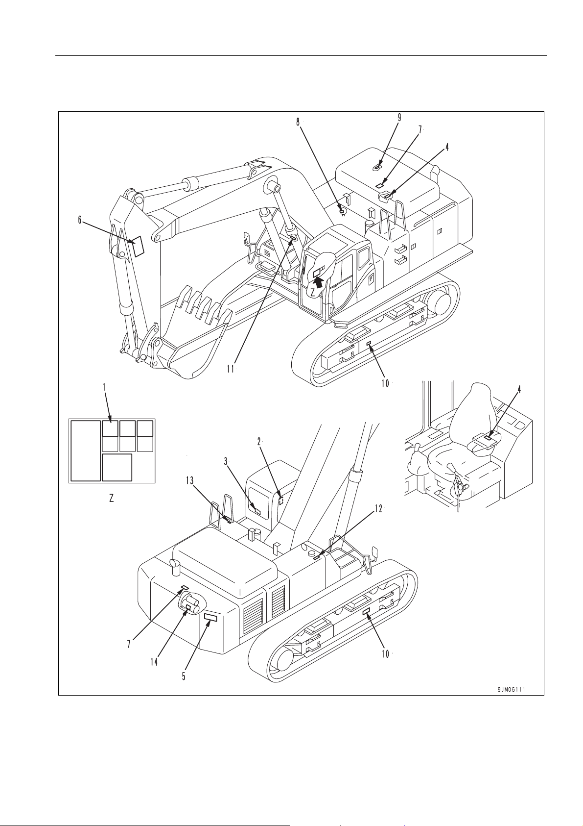
LOCATION OF SAFETY LABELS 2
A
2-5
SAFETY LABELS SAFETY
SAFETY LABELS 2
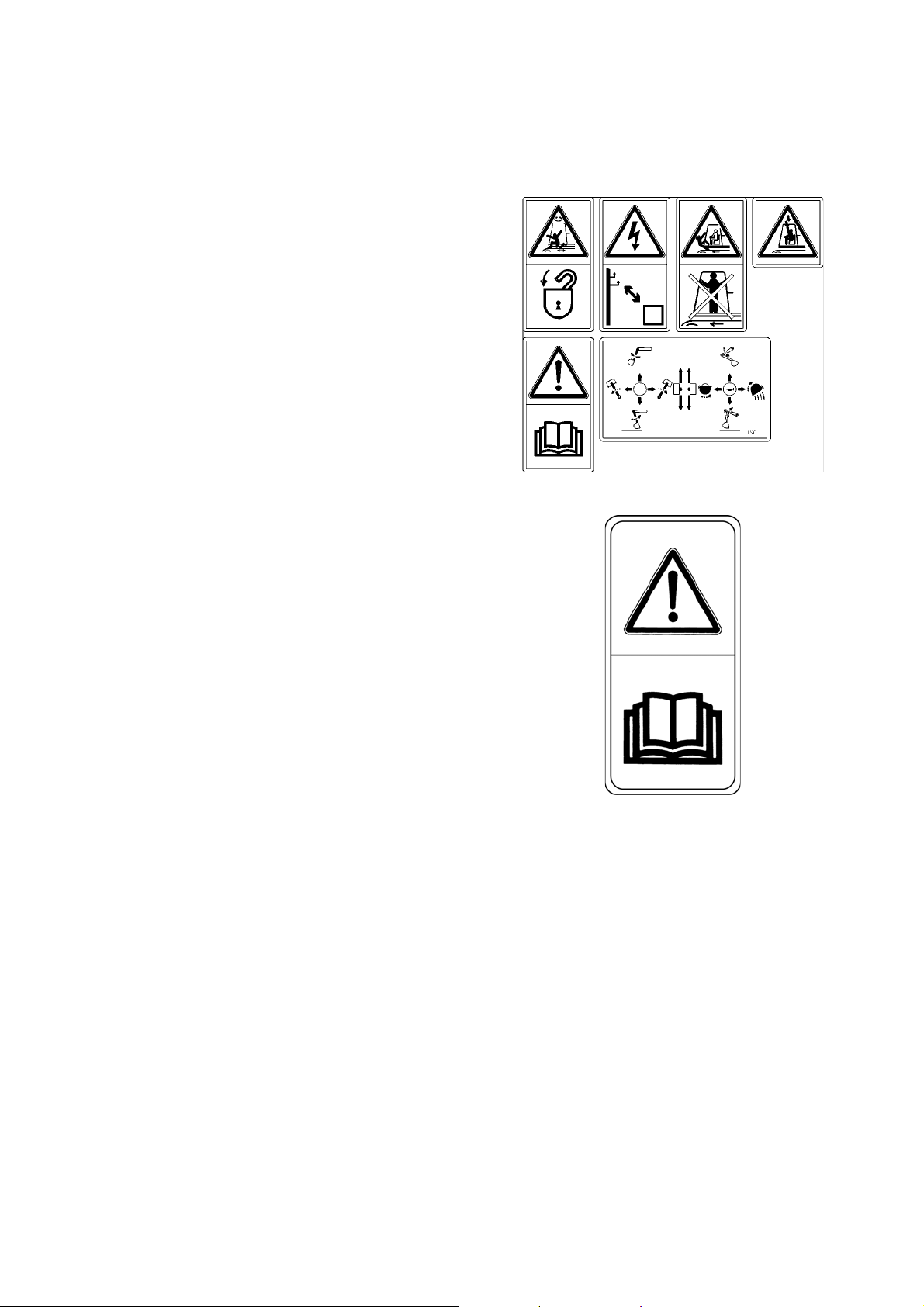
1. (207-00-K1951)
q Warnings for operation, inspection and maintenance
q Improper operation and maintenance can cause serious
injury or death.
q Read the manual and labels before operation and mainte-
nance.
Follow instructions and warnings in manual and in labels
on machine.
a. Keep the manual in machine cab near operator.
q Warning!
q Read the manual before operating, maintenance, disas-
sembly, assembly and transportation.
2-6
SAFETY SAFETY LABELS
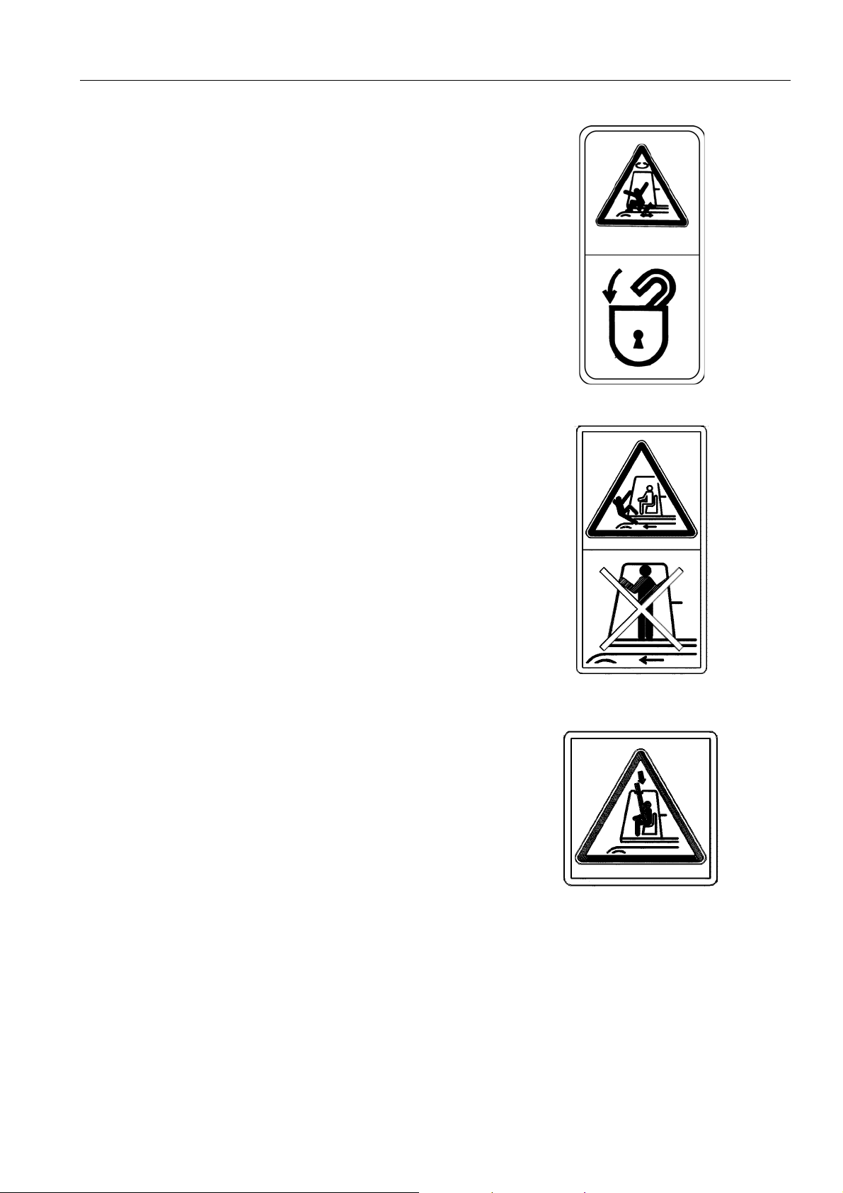
b. Always apply lock when leaving operator’s seat.
c. WARNING - No passengers
q No passengers allowed to ride on machine while it is mov-
ing
d. WARNING - DANGER OF FALLING OBJECTS
q Do not operate where a danger of falling objects exists.
Consult your dealer for fitting of FOPS protection
2-7
SAFETY LABELS SAFETY
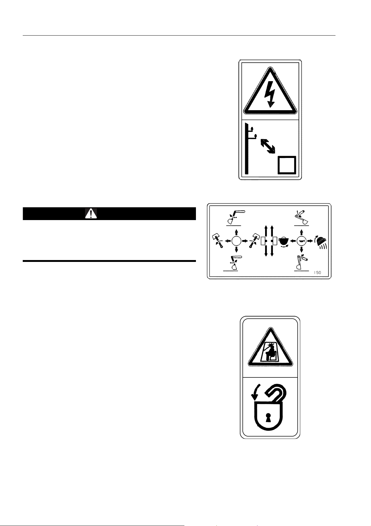
.e. HAZARDOUS - Voltage hazard
q Sign indicates an electrocution hazard if the machine is
brought too near electric power lines.
q Keep a safe distance from electric power lines.
q f. Control levers operational function diagram.
WARNING
In order to prevent an accident resulting in injury or death
caused by error-operation, confirm the machine motion
and indicated operating pattern, when operating
machines. Pay attention to the circumference and operate
slowly when confirming the machine motion.
2. (20E-00-K1230)
q Warning when opening front window
q Sign indicates a hazard from falling window.
q After raising window, be sure to lock it in place with lock
pins.
2-8
 Loading...