

Page 1
OPTIONAL EQUIPMENT
● Additional counterweight
(500 kg 1,100 lb)
● Alternator, 60A
● Arm, 3000 mm 9'10"
● Arm, 2100 mm 6'11"
● Blade assembly
(Bolt-on cutting edge type)
● Blade assembly
(Welded cutting edge type)
● Hydraulic control unit
—1 additional actuator
● Rear view monitoring system
● Shoes
—
600 mm 24"
triple grouser
—
700 mm 28"
triple grouser
—
500 mm 20" rubber pad (road liner)
● Track roller guard
● Track frame undercover
● Travel motor
(Increased drawbar pull type)
PC138US-8 Shoe: 500 mm 20" Arm: 2.5 m 8'2" Unit: kg lb
A 3.0 m 10' 4.6 m 15' 6.1 m 20' Maximum
B CfCsCfCsCfCsCfCs
6.1 m *3060 *3060 *1690 *1690
20' *6,750 *6,750 *3,730 *3,730
3.0 m *5770 *5770 *4320 2990 2880 1830 *1580 1370
10' *12,720 *12,720 *9,530 6,600 6,350 4,040 *3,490 3,040
0.0 m *5630 4840 4260 2600 2690 1660 *1940 1290
0' *12,420 10,670 9,390 5,730 5,950 3,680 *4,280 2,850
–3.0 m *6040 4820 4180 2540 3000 1850
–10' *13,330 10,640 9,230 5,600 6,630 4,090
LIFTING CAPACITY
Equipment:
● Boom: 4.6 m 15'1"
● Bucket: 0.50 m30.65 yd
3
● Counterweight: 3250 kg 7,160 lb
A: Reach from swing circle
B: Bucket hook height
C: Lifting capacity
Cf: Rating over front
Cs: Rating over side
: Rating at maximum reach
PC138US-8 Shoe: 500 mm 20" Arm: 3.0 m 9'10" Unit: kg lb
A 3.0 m 10' 4.6 m 15' 6.1 m 20' Maximum
B CfCsCfCsCfCsCfCs
6.1 m *2690 *2690 *1580 *1580 *1380 *1380
20' *5,940 *5,940 *3,480 *3,480 *3,050 *3,050
3.0 m *3690 *3690 *3740 3040 2900 1850 *1280 1200
10' *8,150 *8,150 *8,250 6,700 6,390 4,080 *2,830 2,660
0.0 m *5990 4830 4240 2580 2670 1640 *1530 1120
0' *13,200 10,660 9,360 5,700 5,900 3,630 *3,370 2,480
–3.0 m *5990 4680 4100 2450 2620 1590 2510 1530
–10' *13,210 10,330 9,040 5,410 5,780 3,520 5,540 3,370
PC138US-8 Shoe: 500 mm 20" Arm: 2.1 m 6'11" Unit: kg lb
A 3.0 m 10' 4.6 m 15' 6.1 m 20' Maximum
B CfCsCfCsCfCsCfCs
6.1 m *3240 3120 *2100 *2100
20' *7,150 6,890 *4,650 *4,650
3.0 m *6480 5720 *4630 2940 2850 1810 *1950 1510
10' *14,300 12,620 *10,220 6,500 6,290 4,000 *4,310 3,340
0.0 m *5570 4800 4240 2590 2700 1670 2310 1420
0' *12,280 10,590 9,360 5,710 5,950 3,680 5,090 3,140
–3.0 m *6270 4880 4,230 2580 3500 2160
–10' *13,830 10,770 9,340 5,700 7,710 4,770
* Load is limited by hydraulic capacity rather than tipping. Ratings are based on SAE Standard No. J/ISO 10567. Rated loads do not exceed 87% of
hydraulic lift capacity or 75% of tipping load.
www.Komatsu.com
CEN00183-00 Materials and specifications are subject to change without notice.
is a trademark of Komatsu Ltd. Japan.
Printed in Japan 200612 IP.As(10)
HORSEPOWER
Gross: 72.1 kW 96.6 HP @ 2200 rpm
Net: 68.4 kW 91.7 HP @ 2200 rpm
OPERATING WEIGHT
13480– 13850 kg 29,720–30,540 lb
BUCKET CAPACITY
0.18– 0.6 m
3
0.24– 0.78 yd
3
Photo may include optional equipment.
PC138US-8
PC
138US
HYDRAULIC EXCAVATOR
Photo may include optional equipment.
Page 2
2
Productivity Features
●
High Mobility
• Large drawbar pull and steering force are evident when
operating on a slope or other rough terrain.
• The machine travel speed changes automatically to Hi or
Lo at optimal points according to the travel load.
See page 5.
● High Stability
The PC138US-8 offers exceptional lifting capacity and high
stability with a large counterweight.
See page 5.
● Mode Selection
• Five working modes designed to match engine speed,
pump delivery and system pressure.
See page 5.
3
Photo may include optional equipment.
WALK-AROUND
H YDRAULIC E XCAVATOR
HYDRAULIC EXCAVATOR
PC138US-8
PC138US-8 0
HORSEPOWER
Gross: 72.1 kW 96.6 HP @ 2200 rpm
Net: 68.4 kW 91.7 HP @ 2200 rpm
OPERATING WEIGHT
13480 – 13850 kg
29,720 – 30,540 lb
BUCKET CAPACITY
0.18 – 0.6 m
3
0.24 – 0.78 yd
3
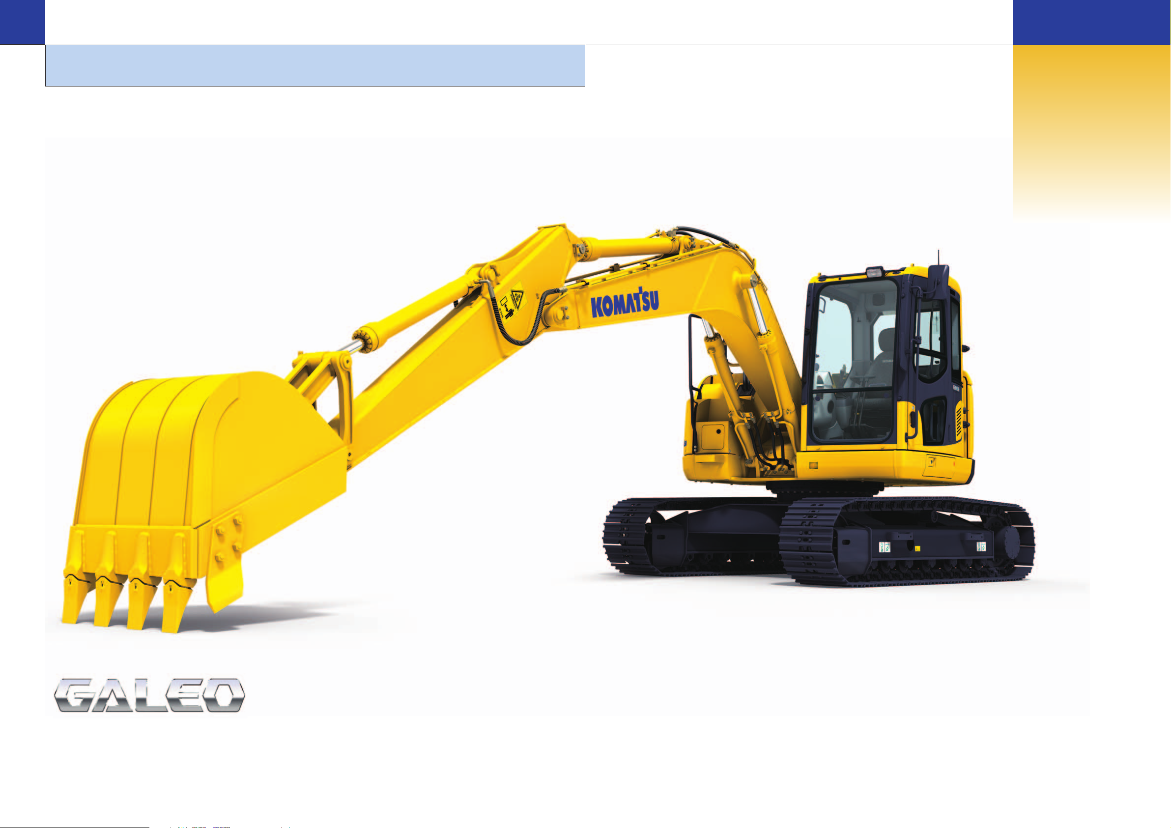
Genuine Answers for Land
and
Environment Optimization
Komatsu’s PC138US-8 Series Hydraulic Excavators have a short tail
swing profile, designed specifically for work in confined areas. By reducing tail swing, the
PC138US-8 is perfect for work on road ways, bridges, in urban areas, or anywhere space is limited. The
PC138US-8 Series provides the performance and productivity you expect from Komatsu equipment.
Ecology and Economy Features
● Low Emission Engine
A powerful turbocharged and air-to-air aftercooled Komatsu SAA4D95LE-5 provides
68.4 kW 91.7 HP. This engine is EPA Tier 3 and EU Stage 3A emissions ready,
without sacrificing power or machine productivity.
● Low Operation Noise
The dynamic noise is reduced providing low noise
operation.
See page 4.
Upper Structure Features
• Slip resistant surfaces for
improved foot traction
• Rear view monitoring system
(optional)
See page 9.
Operation Features
● Small Tail Swing
• Excellent operation in tight quarters with small tail swing radius
design
• Round profile provides short protrusion of front and rear portion of
the upper structure.
• Occupies small road width for operation on narrow roads.
See pages 6 and 7.
Larger Comfortable Cab
• Low noise cab design with
viscous cab mounting
• Sliding convex door facilitates
easy entrance in confined areas.
• Large cab improves working
space.
See page 8.
Easy Maintenance
• Long replacement interval of hydraulic oil
and hydraulic filter
• Remote mounted engine oil filter and fuel
drain valve for easy access
• Equipped with the fuel pre-filter as standard
(with water separator)
• Side-by-side cooling function enables only
the cooling unit to be attached and detached.
• Equipped with the Equipment Management
Monitoring System (EMMS) monitoring system.
See pages 10 and 11.
• Wider Working Ranges : Job sites that require a long upper
reach, such as demolition and slope cutting also benefit from
the increased digging and dumping ranges of the PC138US-8.
See page 7.
Excellent Reliability and
Durability
• High rigidity work equipment
• Sturdy frame structure
• Reliable Komatsu manufactured
major components
See page 11.
Large TFT LCD
Monitor
• Easy-to-see and use 7" large
multi-function color monitor
• Can be displayed in 12
languages for global
support.
TFT : Thin Film Transistor
LCD : Liquid Crystal Display
See page 11.
Page 3
Komatsu Technology
Komatsu develops and produces all major
components in house such as engines,
electronics and hydraulic components.
Combining “Komatsu Technology”, and
customer feedback, Komatsu is achieving
great advancements in technology.
To achieve both high levels of productivity and
economical performance, Komatsu has
developed the main components with a total
control system. The result is a new generation
of high performance and environment-friendly
excavators.
4
PRODUCTIVITY & ECOLOGY FEATURES
HYDRAULIC EXCAVATOR
5
Low Emission Engine
Komatsu SAA4D95LE-5 is EPA Tier 3
and EU Stage 3A emissions ready.
Low Operation Noise
Enables low noise operation using the low-noise engine and
methods to cut noise at source.
Electronically controlled common rail type engine
• Multi-staged injection
• Highly rigid cylinder block
Low noise design
• Optimal arrangement of sound absorbing materials
• Partition between the cab and engine room
• Airtight valve room
H YDRAULIC E XCAVATOR
PC138US-8
PC138US-8
0
High Mobility
The PC138US-8 exceptional travel performance is provided
by single pump with double flow, and it demonstrates superb
maneuverability while operating at its optimum travel speed. It
exhibits a large drawbar pull for moving on job sites, traveling
in rough
terrain and
climbing
steep slopes.
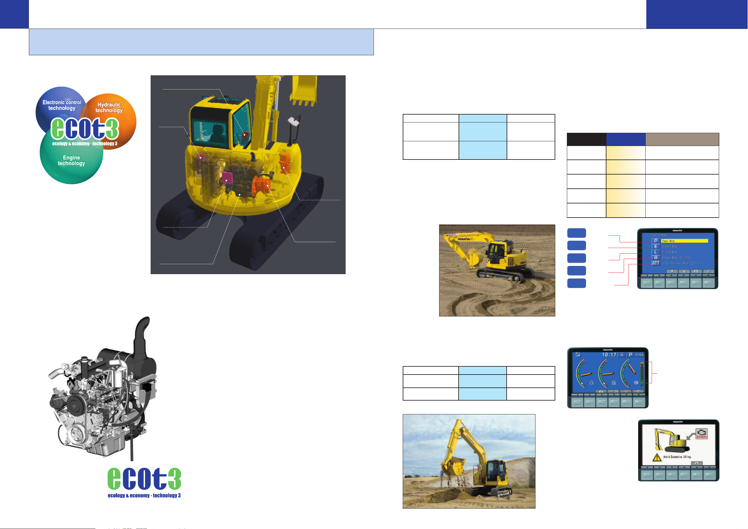
Working Mode Application Advantage
Power mode
● Maximum production/power
P
● Fast cycle times
E
Economy ● Good cycle times
mode ● Better fuel economy
L
Lifting mode ● Suitable attachment speed
Breaker ● Optimum engine rpm,
B
mode hydraulic flow
Attachment ● Optimum engine rpm,
ATT
mode hydraulic flow, 2way
Working Modes Selectable
The PC138US-8 excavator is equipped with five working
modes (P, E, L, B and ATT mode). Each mode is designed to
match engine speed and pump speed with the current
application. This provides the flexibility to match equipment
performance to the job at hand.
Large Digging Force
The PC138US-8 has a large bucket digging force and arm
crowd force, that facilitates digging hard rock-bed. Digging
force ISO rating.
High Stability
The PC138US-8 offers exceptional lifting capacity and high
stability with a large cast-iron counterweight that requires no
additional clearance.
*At maximum reach, ground level height and overside.
*PC120-6 measured with power max.
PC138US-8 PC120-6*
Bucket digging force 93.2 kN 93.4 kN
9500 kgf 9520 kgf
20,950 lbf 20,990 lbf
Arm crowd force 61.8 kN 63.7 kN
6300 kgf 6500 kgf
13,890 lbf 14,330 lbf
PC138US-8 PC120-6
Lifting capacity* 1290 kg 1150 kg
2,850 lb 2,500 lb
Weight of 3250 kg 2255 kg
counterweight 7,160 lb 4,960 lb
Eco-gauge that Assists Energy-saving Operations
The Eco-gauge on the right side of the multi-function color
monitor provides environment-friendly energy-saving
operation. Allows focus on operation in the green range with
reduced CO
2
emissions and efficient fuel consumption.
E
P
Fuel priority
E mode
Work priority
P mode
L
L mode
B
B mode
AT T
ATT mode
Idling Caution
To prevent unnecessary
fuel consumption, an idling
caution is displayed on the
monitor, if the engine idles
for 5 minutes or more.
Eco-gauge
Seven-inch TFT liquid crystal display
Hydraulic system
controller
Electronic control
unit for engine
Engine
Heavy duty HPCR
Common Rail)
(High Pressure
system
Hydraulic control valve
Flow divide/merge control
with EPC
Main pump
Single pump with double
flow system
Page 4

Wider Working Ranges
Raising the boom on the PC138US-8 to a wider
angle enhances overall working performance.
Job sites that require a long upper reach, such as
demolition and slope cutting, also benefit from the
increased digging and dumping ranges of the
PC138US-8.
PC120
3460 mm 11'4"
Minimum implement
swing radius
1980 mm 6'6"
Tail swing radius
1480 mm 4'10"
Reduced
tail swing
radius
650 mm
2'2"
Reduced
implement
swing
radius
350 mm
1'2"
6
Short Implement Swing Radius:
1980 mm 6'6" boom raising angle of
the PC138US-8 is larger than a
conventional profile excavator. The
result is reduced front implement
swing radius.
Safe Operation with Small Tail Swing Even in Confined Areas
Short Tail Swing Radius:
1480 mm 4'10" The short tail swing
radius of the PC138US-8 allows the
machine to work in more confined
areas than a conventional machine.
OPERATION FEATURES
H YDRAULIC E XCAVATOR
HYDRAULIC EXCAVATOR
PC138US-8
PC138US-8 0
Lane Width
3.5 m 11'6"
3460 mm
11'4"
PC138US-8
PC120-6
PC138US-8
PC138US-8
9340 mm 30’8"
5480 mm 18’0"
Max. digging depth
Max. digging height
PC138US-8
8300 mm 27’3"
Max. digging reach
Roadwork
When performing roadwork, protrusion of the machine into the
unoccupied lane is kept minimal since the rear portion of the
upper structure protrudes slightly from the track at swing. This
allows a dump truck to be positioned closer to the track of the
machine. The operator is able to load materials efficiently onto
the front of the dump body at ease since ample dumping reach
is assured for the loading. Large working space is not required
for the machine.
Logging and forest roadwork
Since the protrusion of the rear portion of the upper
structure is kept minimal, there is less possibility of the
counterweight hitting against a
tree or a slope, allowing the
operator to operate the
machine at ease. Furthermore,
large digging height facilitates
slope finishing work. Large
drawbar pull assures
smooth and powerful
traveling even on rough
terrain.
Demolition
The machine needs less working space and can perform
efficient demolition work since it has large and ample
digging height.
Protrusion from
the track (mirror)
295 mm 11.6"
(hand rail)
351mm 13.8’’
235mm 9.3’’
235mm 9.3’’
144mm 5.7’’
Protrusion from
the track (rear)
Protrusion from
the track (rear)
Protrusion from the track
(handrail)
Round Profile of both Front and Rear Portion of the
Upper Structure
Komatsu hydraulic excavators with small tail swing radius design
adopt the round profile for both left and right corners of the front
portion of the upper structure as well as its rear portion that features
less protrusion from the track at swing. The round profile design
allows the machine to work in tight quarters.
PC138US-8 PC120-6
Maximum digging height
9340 mm 8610 mm
30'8" 28'3"
Maximum digging depth 5480 mm 5520 mm
18'0" 18'1"
Maximum dumping height 6840 mm 6170 mm
22'5" 27'2"
7
Logging road width
3–4 m 9'10"–13'1"
Photo may include optional equipment.
Page 5

Rubber
Silicon Oil
8 9
WORKING ENVIRONMENT
H YDRAULIC E XCAVATOR
HYDRAULIC EXCAVATOR
PC138US-8
PC138US-8 0
Automatic Air Conditioner
Automatic air conditioner is utilized.
The bi-level control function keeps the
operator's head and feet cool and
warm respectively. This improved air
flow function keeps the inside of the
cab comfortable throughout the year.
Defroster function keeps cab glass clear.
Sliding Convex Door
The sliding convex door facilitates easy
entrance in confined areas.
Large Cab
Large cab provides ample operation
space. The cab has wide doorway for
easy access.
PC138US-8 cab interior is spacious and provides a comfortable working
environment…
Large Comfortable
Cab
Multi-position Controls
The multi-position, PPC (pressure
proportional control) levers allow the
operator to work in comfort while
maintaining precise control.
A double-slide mechanism allows the
seat and controllers to move together
or independently, allowing the operator
to position the seat and controllers for
maximum productivity and comfort.
Low Cab Noise
Cab is highly rigid and has excellent
sound absorption ability. Thorough
improvement of noise source reduction
and use of low noise engine, hydraulic
equipment, and air conditioner allows
this machine to generate a low level of
noise.
Comfortable Ride with
Viscous Cab Mounts
Viscous mounts are adopted for cab
mount system. The cab mount system
absorbs shocks
and aids vibration
reduction to provide
comfortable ride.
Features
New Cab Design for Hydraulic
Excavators
The cab is designed specifically for
hydraulic excavators and gains
reinforced strength from the pipe-
structured cab framework. The cab
framework provides the high durability
and impact resistance with very high
impact absorbency. The seat belt
keeps the operator in the safety of the
cab in the event of a rollover.
Retractable Seat Belt
Easy-to-use retractable seat belt is
employed.
Tempered and Tinted Glass
The glass features high strength and
blocks ultraviolet rays.
Emergency Escape Hammer
The cab is equipped with an
emergency escape hammer for
breaking the rear window glass in case
of an emergency.
Travel Alarm
An alarm is installed as standard
equipment to give other workers a
warning when the machine travels in
forward or reverse.
Pump/engine Room Partition
Pump/engine room partition prevents
oil from spraying on the engine if a
hydraulic hose should burst.
Anti-slip Plates
Highly durable slip resistant plates
maintain superior foot traction
performance.
Lock Lever
When lock lever is placed in lock
position all hydraulic controls (travel,
swing, boom,
arm and
bucket) are
inoperable.
Rear View Monitoring System
(optional)
The operator can
view the rear of
the machine with a
color monitor
screen.
Wide Visibility
The right side window pillar has been
removed and the rear pillar reshaped
to provide improved visibility.
Skylight
Skylight with
window can be
opened for
overhead
visibility.
Monitor for rear
view camera
Pressurized Cab
Auto air conditioner, air filter and a
higher internal air pressure prevent
external dust from entering the cab.
Lever shown in lock
position
Page 6

Valv e
room
Engine
Control
valve
Radiator
After cooler
Oil cooler
Cab
Fuel tank
Hydraulic
tank
12
Tool Box
1
11
2
3
4
5
7
9
8
6
10
1. Swing machinery oil filler
2.
Swing machinery dip stick
3.
Fuel fiter (with water separator)
4. Coolant reserve tank
5. Fuel drain valve
6. PTO oil filler
7. Engine oil filter
8. Engine oil dipstick
9. Engine oil filler
10.
Windshield washer tank
11. Batteries
12. Air cleaner
10
Easy Maintenance
Komatsu designed the PC138US-8 to
have easy service access. By doing so,
routine maintenance and servicing are
less likely to be skipped, which can mean
a reduction in costly downtime later on.
Here are some of the many service
features found on the PC138US-8.
Optimum Maintenance Layout
With the left and right side service
doors, it is possible to access the major
maintenance points from ground level.
Furthermore, the fuel drain valve,
engine oil filter, swing machinery oil
filler, and PTO oil filler are remote
mounted, facilitating easy maintenance.
Excellent Reliability and Durability
11
MAINTENANCE FEATURES
H YDRAULIC E XCAVATOR
PC138US-8
Side-by-side Cooling
The oil cooler, aftercooler and radiator
are installed side by side. As a result,
it is very easy to clean the radiator,
etc. In addition, the operator can
remove and
install the
aftercooler,
radiator and
oil cooler in a
short time.
Large Tool Box
Large tool box provides plenty of
space. Grease
pump storage
space is also
provided.
Long Greasing Interval
Special hard material is used for the
bushings of the work equipment to
lengthen greasing interval. All
bushing lubrication intervals of work
equipment except arm top bushing
are 500 hours, reducing maintenance
costs.
Maintenance
Costs Reduced
Eco-white Filter Element
High performance filters are used in the hydraulic circuit and
engine. Longer hydraulic oil, hydraulic oil filter, engine oil and
engine oil filter element replacement intervals significantly
reduce maintenance costs.
Equipped with the Fuel Pre-filter
(with Water Separator)
Removes water and
contaminants in the
fuel to prevent fuel
problems.
Washable Floor
The PC138US-8’s floor is easy to keep
clean. The gently inclined surface has
a flanged floor mat and drainage holes
to facilitate run off.
Large TFT LCD Monitor
Basic
operation
switches
Air conditioner
operation
switches
Function
switches
8
1 2 3
4 5 6
7
5
6
1 2 3
4
6
7
8
1
2
3
4
5
1
2
3
4
5
6
Auto-decelerator
Working mode
Travel speed
Engine water
temperature gauge
Hydraulic oil
temperature gauge
Fuel gauge
Eco-gauge
Function switches menu
Auto-decelerator
Working mode selector
Traveling selector
Buzzer cancel
Wiper
Windshield washer
Indicators
Basic operation
switches
Large multi-lingual LCD Monitor
A large user-friendly color monitor enables safe, accurate and smooth work.
Improved screen visibility is achieved by the use of TFT liquid crystal display that
can easily be read at various angles and lighting conditions. Simple and easy to
operate switches. Industry first function keys facilitate multi-function operations.
Displays data in 12 languages to globally support operators around the world.
EMMS (Equipment Management
Monitoring System)
Monitor function
Controller monitors engine oil level,
coolant temperature and battery
charge, etc. If
controller finds
any abnormality,
it is displayed
on the LCD.
Maintenance function
Monitor informs replacement time of oil
and filters on
LCD when the
replacement
interval is
reached.
Trouble data memory function
Monitor stores abnormalities for
effective troubleshooting.
High Rigidity Work Equipment
Boom and arms are constructed of thick
plates of high tensile strength steel. In
addition, these structures are designed
with large cross-sectional areas and
generous use of castings. The result is
working attachments that exhibit long
term durability and high resistance to
bending and torsional stress.
Sturdy Frame Structure
The revolving frame, center frame and
undercarriage are designed by using
the most advanced three-dimensional
CAD and FEM analysis technology.
Metal Guard Rings Protect all
the Hydraulic Cylinders and
Improve Reliability.
DT-type Connectors
DT-type connectors seal tight and have
higher
reliability.
O-ring Face Seal
The hydraulic hose seal method has
been changed from a conventional taper
seal to an O-ring seal. This provides
improved
sealing
performance.
Waterproof seal
Waterproof
seal
Waterproof seal
Metal guard ring
(Cast iron ring)
Piston ring
Wear ring
Reliable Components
All of the major machine components,
such as engine, hydraulic pump,
hydraulic motors and control valves
are exclusively designed and
manufactured by Komatsu.
Photo may include optional equipment.
Engine oil &
Engine oil filter every
500 hours
Hydraulic oil every 5000 hours
Hydraulic oil filter every 1000 hours
AftercoolerOil cooler
Radiator
Dust-proof net
Page 7

PC138US-8 0
HYDRAULIC EXCAVATOR
12
Shoes Operating Weight Ground Pressure
mm in kg lb kPa kg/cm
2
psi
500 20" 13480 29,720 42.2 0.43 6.11
600 24" 13670 30,140 35.3 0.36 5.12
700 28" 13850 30,540 30.4 0.31 4.41
STANDARD EQUIPMENT
● Air cleaner, double element
with auto dust evacuator
● Auto air conditioner
● Alternator, 35 Ampere, 24 V
● Batteries, 64 Ah/2 x 12 V
● Cab which includes: antenna, AM/FM
radio, floor mat, intermittent front windshield wiper and washer, large ceiling
hatch, pull-up front window, removable
lower windshield, sliding rear
window, sliding seat
● Cooling fan, mixed flow with fan guard
● Counterweight, 3250 kg 7,160 lb
● Dustproof net for radiator and oil cooler
● Monitor panel
● Light, one front
● Auto deceleration
● Pump/engine partition cover
● Shoe, 500 mm 19.7" triple grouser
● Starting motor 4.5 kW
● Swing holding brake
● Travel alarm
SPECIFICATIONS
ENGINE
Model . . . . . . . . . . . . . . . . . . . . . . . . . . . . . Komatsu SAA4D95LE-5
Type . . . . . . . . . . . . . . . . . . . . . . . . . . . . . . . . Water-cooled, 4-cycle
Aspiration . . . . . . . . . . . . . . Turbocharged, and air-to-air aftercooled
Number of cylinders . . . . . . . . . . . . . . . . . . . . . . . . . . . . . . . . . . . . 4
Bore x stroke . . . . . . . . . . . . . . . . . . 95 mm x 115 mm 3.74" x 4.53"
Piston displacement. . . . . . . . . . . . . . . . . . . . . . . . . . 3.26 ltr 199 in
3
Governor . . . . . . . . . . . . . . . . . . . . . . . . All-speed control, electronic
Flywheel horsepower
ISO 9249 / SAE J1349. . . . . . . . . . . . . . . Gross 72.1 kW 96.6 HP
. . . . . . . . . . . . . . . . . . . . . . . . . . . . . . . . . . Net 68.4 kW 91.7 HP
Rated rpm . . . . . . . . . . . . . . . . . . . . . . . . . . . . . . . . . . . 2200 rpm
Fuel system . . . . . . . . . . . . . . . . . . . . . . . . . . . . . . . . Direct injection
Lubrication system
Method . . . . . . . . . . . . . . . . . . . . . . . Gear pump, force-lubrication
Filter . . . . . . . . . . . . . . . . . . . . . . . . . . . . . . . . . . . . . . . . Full-flow
Air cleaner . . . . . . . . . . . . . . . . . . . . . Dry-type with double elements
. . . . . . . . . . . . . . . . . and auto dust evacuator, plus dust indicator
Meets 2006 EPA Tier 3 and EU Stage 3A
Starting motor . . . . . . . . . . . . . . . . . . . . . . . . . . . . . . . . 4.5 kW/24 V
Alternator . . . . . . . . . . . . . . . . . . . . . . . . . . . . . . . . . . . . . 35 A/24 V
Battery . . . . . . . . . . . . . . . . . . . . . . . . . . . . . . . . . . . 64 Ah/2 x 12 V
HYDRAULICS SYSTEM
Type . . . . . . . . . . . . . . . . . . . . . . HydrauMind (Hydraulic Mechanical
Intelligence New Design) system,
Closed-center system with load-sensing valve
and pressure-compensated valve
Main pump:
Type . . . . . . . . . . . . . . . . . . . . . . . . . Variable capacity piston type
Pumps for . . . . . . . . Boom, arm, bucket, swing, and travel circuits
Maximum flow . . . . . . . . . . . . . . . . 242 ltr/min 63.9 U.S. gal/min
Hydraulic motors:
Travel . . . . . . . . . . . . . . . . . . . 2 x piston motor with parking brake
Swing . . . . . . . . . . . . . . 1 x piston motor with swing holding brake
Relief valve setting:
Implement, travel circuit . . . . . . 34.8 MPa 355 kgf/cm25,050 psi
Swing circuit. . . . . . . . . . . . . . . 27.1 MPa 276 kgf/cm23,920 psi
Pilot circuit . . . . . . . . . . . . . . . . . 3.2 MPa 33 kgf/cm2470 psi
Hydraulic cylinders:
(Number of cylinders – bore x stroke)
Boom . . . . . . . . . . . . . . . . . . 2–105 mm x 1055 mm 4.1" x 41.5"
Arm . . . . . . . . . . . . . . . . . . . . 1–110 mm x 1175 mm 4.5" x 46.3"
Bucket. . . . . . . . . . . . . . . . . . . . 1–95 mm x 885 mm 3.9" x 34.8"
SWING SYSTEM
Driven by . . . . . . . . . . . . . . . . . . . . . . . . . . . . . . . . . Hydraulic motor
Swing reduction . . . . . . . . . . . . . . . . . . . . . . . . . . . . . Planetary gear
Swing circle lubrication . . . . . . . . . . . . . . . . . . . . . . . Grease-bathed
Swing lock . . . . . . . . . . . . . . . . . . . . . . . . . . Wet, multiple-disc brake
Swing speed . . . . . . . . . . . . . . . . . . . . . . . . . . . . . . . . . . . . 11.0 rpm
DRIVES AND BRAKES
Steering control . . . . . . . . . . . . . . . . . . . . . . . Two levers with pedals
Drive method . . . . . . . . . . . . . . . . . . . . . . . . . . . . . . Fully hydrostatic
Maximum drawbar pull . . . . . . . . . . . . . 123 kN 12500 kgf 27,560 lbf
Maximum travel speed: High . . . . . . . . . . . . . . . . . 5.1 km/h 3.2 mph
Low . . . . . . . . . . . . . . . . . 2.9 km/h 1.8 mph
Service brake . . . . . . . . . . . . . . . . . . . . . . . . . . . . . . . Hydraulic lock
Parking brake . . . . . . . . . . . . . . . . . . . . . . . . . . . . Wet, multiple-disc
UNDERCARRIAGE
Center frame . . . . . . . . . . . . . . . . . . . . . . . . . . . . . . . . . X-leg frame
Track frame . . . . . . . . . . . . . . . . . . . . . . . . . . . . . . . . . . Box-section
Seal of track . . . . . . . . . . . . . . . . . . . . . . . . . . . . . . . . . Sealed track
Track adjuster . . . . . . . . . . . . . . . . . . . . . . . . . . . . . . . . . . Hydraulic
Number of shoes . . . . . . . . . . . . . . . . . . . . . . . . . . . . . 43 each side
Number of carrier rollers . . . . . . . . . . . . . . . . . . . . . . . . . 1 each side
Number of track rollers . . . . . . . . . . . . . . . . . . . . . . . . . . 7 each side
COOLANT AND LUBRICANT
CAPACITY (REFILLING)
Fuel tank . . . . . . . . . . . . . . . . . . . . . . . . . . . . . 195 ltr 51.5 U.S. gal
Radiator . . . . . . . . . . . . . . . . . . . . . . . . . . . . . 12.4 ltr 3.3 U.S. gal
Engine. . . . . . . . . . . . . . . . . . . . . . . . . . . . . . . 11.0 ltr 2.9 U.S. gal
Final drive, each side . . . . . . . . . . . . . . . . . . . . 2.5 ltr 0.7 U.S. gal
Swing drive . . . . . . . . . . . . . . . . . . . . . . . . . . . . 2.5 ltr 0.7 U.S. gal
Hydraulic tank . . . . . . . . . . . . . . . . . . . . . . . . . 69.0 ltr 18.2 U.S. gal
OPERATING WEIGHT (APPROXIMATE)
Operating weight including 4600 mm 15'1" one-piece boom,
2500 mm 8'2" arm, SAE heaped 0.50 m30.65 yd3backhoe bucket,
rated capacity of lubricants, coolant, full fuel tank, operator, and
standard equipment.
Page 8

PC138US-8 0
13
Boom Length 4600 mm 15'1" 4600 mm 15'1" 4600 mm 15'1"
Arm Length 2500 mm 8'2" 3000 mm 9'10" 2100 mm 6'11"
A Overall length 7260 mm 23'10" 7160 mm 23'6" 7275 mm 23'10"
B Overall height (to top of boom) 2850 mm 9'4" 3210 mm 10'6" 2690 mm 8'10"
C Length on ground (transport) 4400 mm 14'5" 4290 mm 14'1" 4660 mm 15'3"
Boom 4600 mm 15'1" 4600 mm 15'1" 4600 mm 15'1"
Arm 2500 mm 8'2" 3000 mm 9'10" 2100 mm 6'11"
A Maximum digging height 9340 mm 30'8" 9700 mm 31'10" 9020 mm 29'7"
B Maximum dumping height 6840 mm 22'5" 7350 mm 24'1" 6525 mm 21'5"
C Maximum digging depth 5480 mm 18'0" 5900 mm 19'4" 5070 mm 16'8"
D Maximum vertical wall digging depth 4900 mm 16'1" 5340 mm 17'6" 4490 mm 14'9"
E Maximum digging depth of cut for
2440 mm 8' level 5265 mm 17'3" 5715 mm 18'9" 4830 mm 15'10"
F Maximum digging reach 8300 mm 27'3" 8720 mm 28'7" 7930 mm 26'0"
G Maximum digging reach at ground 8180 mm 26'10" 8600 mm 28'3" 7805 mm 25'7"
H Minimum swing radius 1980 mm 6'6" 2265 mm 7'5" 1845 mm 6'1"
ISO Bucket digging force 93.2 kN 88.3 kN 88.3 kN
9500 kgf 20,950 lbf 9000 kgf 19,840 lbf 9000 kgf 19,840 lbf
Arm crowd force 61.8 kN 55.9 kN 71.6 kN
6300 kgf 13,890 lbf 5700 kgf 12,570 lbf 7300 kgf 16,090 lbf
SAE Bucket digging force 81.4 kN 78.0 kN 78.0 kN
8300 kgf 18,300 lbf 7950 kgf 17,530 lbf 7950 kgf 17,530 lbf
Arm crowd force 60.8 kN 54.4 kN 69.6 kN
6200 kgf 13,670 lbf 5550 kgf 12,240 lbf 7100 kgf 15,650 lbf
Bucket Capacity (heaped) Width
Number
Arm Length
SAE, PCSA CECE
Without Side With Side Weight 2500 mm 3000 mm 2100 mm
Cutters Cutters
of Teeth
8'2" 9'10" 6'11"
0.18 m
3
0.16 m
3
450 mm 570 mm 256 kg
3
0.24 yd
3
0.21 yd
3
17.7" 22.4" 565 lb
0.28 m
3
0.26 m
3
600 mm 720 mm 303 kg
3
0.37 yd
3
0.34 yd
3
23.6" 28.3" 670 lb
0.36 m
3
0.33 m
3
700 mm 820 mm 330 kg
4
0.50 yd
3
0.43 yd
3
27.6" 32.3" 730 lb
0.50 m
3
0.45 m
3
859 mm 979 mm 399 kg
4 X
0.65 yd
3
0.59 yd
3
33.8" 38.5" 880 lb
0.60 m
3
0.55 m
3
1000 mm
NA
436 kg
5 □ X □
0.78 yd
3
0.72 yd
3
39.4" 960 lb
WORKING RANGE
BACKHOE BUCKET AND ARM COMBINATION
DIMENSIONS
—General digging —Light-duty operation X— Not available
G
B
P(D)
O
F
I
J
E
N
Q
M
K
D,L
C
H
A
F
E
C
A
B
G
H
876543201
6
5
4
3
2
1
10
9
8
7
6
5
4
1
3
2
0
D
2440(8')
D Overall width 2490 mm 8'2"
E Overall height (to top of cab) 2815 mm 9'3"
F Ground clearance, counterweight 900 mm 2'11"
G Minimum ground clearance 395 mm 1'4"
H Tail swing radius 1480 mm 4'10"
I Length of track on ground 2880 mm 9'5"
J Track length 3610 mm 11'10"
K Track gauge 1990 mm 6'6"
L Width of crawler 2490 mm 8'2"
M Shoe width 500 mm 19.7"
N Grouser height 20 mm 0.8"
O Machine cab height 1980 mm 6'6"
P Machine cab width 2490 mm 8'2"
Q Distance swing center to rear end 1480 mm 4'10"
HYDRAULIC EXCAVATOR
 Loading...