


SEBM036301
MACHINE MODEL SERIAL NUMBER
PC130-7 70001 and up
• This shop manual may co ntain attachiments and optio nal equipment that are not availabl e in your
area. Please consult your local Komatsu distributor for those items you may require.
Materials and specifications are subject to change without notice.
• PC130-7 mounts the SAA4D95LE-3 engine.
For details of the engine, see the 95-3 Series Engine Shop Manual.
© 2004
All Rights Reserved
Printed in Japan 04-04(02)
00-1
(1)

CONTENTS
No. of page
01 GENERAL ................................................................................................................01-1
10 STRUCTURE AND FUNCTION.................................................................10-1
20 TESTING AND ADJUSTING .......................................................................20-1
30 DISASSEMBLY AND ASSEMBLY.............................To be issued next time
40 MAINTENANCE STANDARD......................................................................40-1
90 OTHERS ....................................................................................................................90-1
00-2 PC130-7
(1)

The affected pages are indicated by the use of the
following marks . It is requested that necessary
actions be taken to these pages according to the
table below.
LIST OF REVISED PAGES
Mark Page
00-1
q
00-2 (1)
q
00-2-1 (1)
Q
00-2-2 (1)
Q
00-2-3 (1)
Q
00-3
00-4
00-5
00-6
00-7
00-8
00-9
00-10
00-11
00-12
00-13
00-14
00-15
00-16
00-17
00-18
00-19
00-20
00-21
00-22
01-1
01-2
01-3
01-4
01-5
01-6
01-7
01-8
01-9
10-1
10-2
10-3
10-4
10-5
Revision
number
(1)
Mark Page
10-6
10-7
10-8
10-9
10-10
10-11
10-12
10-13
10-14
10-15
10-16
10-17
10-18
10-19
10-20
10-21
10-22
10-23
10-24
10-25
10-26
10-27
10-28
10-29
10-30
10-31
10-32
10-33
10-34
10-35
10-36
10-37
10-38
10-39
10-40
10-41
10-42
10-43
10-44
10-45
10-46
Revision
number
Mark Page
10-47
10-48
10-49
10-50
10-51
10-52
10-53
10-54
10-55
10-56
10-57
10-58
10-59
10-60
10-61
10-62
10-64
10-65
10-66
10-67
10-68
10-69
10-70
10-71
10-72
10-73
10-74
10-75
10-76
10-77
10-78
10-79
10-80
10-81
10-82
10-83
10-84
10-85
10-86
10-87
10-88
Mark Indication Action required
Page to be newly added Add
Q
Page to be replaced Replace
q
( ) Page to be deleted Discard
Pages having no mark s a r e tho se pr ev io us ly r evi s ed
or made aditions.
Revision
number
Mark Page
10-89
10-90
10-91
10-92
10-93
10-94
10-95
10-96
10-97
10-98
10-99
10-100
10-101
10-102
10-103
10-104
10-105
10-106
10-107
10-108
10-109
10-110
10-111
10-112
10-113
Revision
number
Mark Page
10-131
10-132
10-133
10-134
10-135
10-136
10-137
10-138
10-139
10-140
10-141
10-142
10-143
10-144
10-145
10-146
10-147
10-148
10-149
10-150
10-151
10-152
10-153
10-154
10-155
Revision
number
10-114
10-115
10-116
10-117
10-118
10-119
10-120
10-121
10-122
10-124
10-125
10-126
10-127
10-128
10-129
10-130
Q
Q
Q
Q
Q
Q
Q
Q
Q
Q
Q
Q
Q
Q
Q
20-1
20-2
20-3
20-4
20-5
20-6
20-7
20-8
20-9
20-10
20-11
20-101
20-102
20-103
20-104
(1)
(1)
(1)
(1)
(1)
(1)
(1)
(1)
(1)
(1)
(1)
(1)
(1)
(1)
(1)
PC130-7 00-2-1
(1)

Mark Page
20-105
Q
20-106
Q
20-107
Q
20-108
Q
20-109
Q
20-110
Q
20-111
Q
20-112
Q
20-113
Q
20-114
Q
20-115
Q
20-116
Q
20-117
Q
20-118
Q
20-119
Q
20-120
Q
20-121
Q
20-122
Q
20-123
Q
20-124
Q
20-125
Q
20-126
Q
20-127
Q
20-128
Q
20-129
Q
20-130
Q
20-131
Q
20-132
Q
20-133
Q
20-134
Q
20-135
Q
20-136
Q
20-137
Q
20-138
Q
20-139
Q
20-140
Q
20-141
Q
20-142
Q
20-143
Q
20-144
Q
20-145
Q
20-146
Q
20-147
Q
20-148
Q
20-149
Q
20-150
Q
20-151
Q
20-152
Q
20-153
Q
20-154
Q
20-155
Q
Revision
number
(1)
(1)
(1)
(1)
(1)
(1)
(1)
(1)
(1)
(1)
(1)
(1)
(1)
(1)
(1)
(1)
(1)
(1)
(1)
(1)
(1)
(1)
(1)
(1)
(1)
(1)
(1)
(1)
(1)
(1)
(1)
(1)
(1)
(1)
(1)
(1)
(1)
(1)
(1)
(1)
(1)
(1)
(1)
(1)
(1)
(1)
(1)
(1)
(1)
(1)
(1)
Mark Page
20-156
Q
20-157
Q
20-158
Q
20-159
Q
20-160
Q
20-161
Q
20-162
Q
20-163
Q
20-164
Q
20-165
Q
20-166
Q
20-167
Q
20-168
Q
20-169
Q
20-170
Q
20-171
Q
20-201
Q
20-202
Q
20-203
Q
20-204
Q
20-205
Q
20-206
Q
20-207
Q
20-208
Q
20-209
Q
20-210
Q
20-211
Q
20-212
Q
20-213
Q
20-214
Q
20-215
Q
20-216
Q
20-217
Q
20-218
Q
20-219
Q
20-220
Q
20-222
Q
20-223
Q
20-224
Q
20-225
Q
20-226
Q
20-228
Q
20-229
Q
20-230
Q
20-231
Q
20-232
Q
20-233
Q
20-234
Q
20-235
Q
20-236
Q
20-237
Q
Revision
number
(1)
(1)
(1)
(1)
(1)
(1)
(1)
(1)
(1)
(1)
(1)
(1)
(1)
(1)
(1)
(1)
(1)
(1)
(1)
(1)
(1)
(1)
(1)
(1)
(1)
(1)
(1)
(1)
(1)
(1)
(1)
(1)
(1)
(1)
(1)
(1)
(1)
(1)
(1)
(1)
(1)
(1)
(1)
(1)
(1)
(1)
(1)
(1)
(1)
(1)
(1)
Mark Page
20-238
Q
20-239
Q
20-240
Q
20-241
Q
20-242
Q
20-243
Q
20-244
Q
20-245
Q
20-246
Q
20-247
Q
20-248
Q
20-249
Q
20-250
Q
20-251
Q
20-252
Q
20-253
Q
20-254
Q
20-255
Q
20-256
Q
20-257
Q
20-258
Q
20-301 (1)
Q
20-302 (1)
Q
20-303 (1)
Q
20-304 (1)
Q
20-305 (1)
Q
20-306 (1)
Q
20-307 (1)
Q
20-308 (1)
Q
20-310 (1)
Q
20-311 (1)
Q
20-312 (1)
Q
20-313 (1)
Q
20-314 (1)
Q
20-315 (1)
Q
20-316 (1)
Q
20-317 (1)
Q
20-318 (1)
Q
20-319 (1)
Q
20-320 (1)
Q
20-321 (1)
Q
20-322 (1)
Q
20-323 (1)
Q
20-324 (1)
Q
20-325 (1)
Q
20-326 (1)
Q
20-327 (1)
Q
20-328 (1)
Q
20-329 (1)
Q
20-330 (1)
Q
20-331 (1)
Q
Revision
number
(1)
(1)
(1)
(1)
(1)
(1)
(1)
(1)
(1)
(1)
(1)
(1)
(1)
(1)
(1)
(1)
(1)
(1)
(1)
(1)
(1)
Mark Page
20-332 (1)
Q
20-333 (1)
Q
20-334 (1)
Q
20-335 (1)
Q
20-336 (1)
Q
20-337 (1)
Q
20-338 (1)
Q
20-339 (1)
Q
20-340 (1)
Q
20-341 (1)
Q
20-342 (1)
Q
20-343 (1)
Q
20-344 (1)
Q
20-345 (1)
Q
20-346 (1)
Q
20-347 (1)
Q
20-348 (1)
Q
20-349 (1)
Q
20-350 (1)
Q
20-351 (1)
Q
20-352 (1)
Q
20-354 (1)
Q
20-355 (1)
Q
20-356 (1)
Q
20-357 (1)
Q
20-358 (1)
Q
20-359 (1)
Q
20-360 (1)
Q
20-362 (1)
Q
20-363 (1)
Q
20-364 (1)
Q
20-365 (1)
Q
20-401 (1)
Q
20-402 (1)
Q
20-403 (1)
Q
20-404 (1)
Q
20-405 (1)
Q
20-406 (1)
Q
20-408 (1)
Q
20-409 (1)
Q
20-410 (1)
Q
20-411 (1)
Q
20-412 (1)
Q
20-413 (1)
Q
20-414 (1)
Q
20-415 (1)
Q
20-416 (1)
Q
20-417 (1)
Q
20-418 (1)
Q
20-419 (1)
Q
20-420 (1)
Q
Revision
number
Mark Page
20-421 (1)
Q
20-422 (1)
Q
20-423 (1)
Q
20-424 (1)
Q
20-425 (1)
Q
20-426 (1)
Q
20-427 (1)
Q
20-428 (1)
Q
20-429 (1)
Q
20-430 (1)
Q
20-431 (1)
Q
20-432 (1)
Q
20-433 (1)
Q
20-434 (1)
Q
20-436 (1)
Q
20-437 (1)
Q
20-438 (1)
Q
20-439 (1)
Q
20-440 (1)
Q
20-441 (1)
Q
20-442 (1)
Q
20-443 (1)
Q
20-444 (1)
Q
20-445 (1)
Q
20-446 (1)
Q
20-447 (1)
Q
20-448 (1)
Q
20-449 (1)
Q
20-450 (1)
Q
20-451 (1)
Q
20-452 (1)
Q
20-453 (1)
Q
20-454 (1)
Q
20-455 (1)
Q
20-456 (1)
Q
20-457 (1)
Q
20-458 (1)
Q
20-459 (1)
Q
20-460 (1)
Q
20-461 (1)
Q
20-462 (1)
Q
20-463 (1)
Q
20-464 (1)
Q
20-465 (1)
Q
20-466 (1)
Q
20-467 (1)
Q
20-468 (1)
Q
20-469 (1)
Q
20-470 (1)
Q
20-471 (1)
Q
20-472 (1)
Q
Revision
number
00-2-2 PC130-7
(1)

Mark Page
20-473 (1)
Q
20-474 (1)
Q
20-475 (1)
Q
20-476 (1)
Q
20-501
Q
20-502
Q
20-504
Q
20-505
Q
20-506
Q
20-507
Q
20-508
Q
20-509
Q
20-510
Q
20-511
Q
20-512
Q
20-513
Q
20-514
Q
20-515
Q
20-516
Q
20-517
Q
20-518
Q
20-519
Q
20-520
Q
20-521
Q
20-522
Q
20-523
Q
20-524
Q
20-525
Q
20-601
Q
20-602
Q
20-603
Q
20-604
Q
20-605
Q
20-606
Q
20-607
Q
20-608
Q
20-609
Q
20-610
Q
20-611
Q
20-612
Q
20-613
Q
20-614
Q
20-615
Q
20-616
Q
20-617
Q
20-618
Q
20-619
Q
20-620
Q
20-621
Q
20-622
Q
20-623
Q
Revision
number
(1)
(1)
(1)
(1)
(1)
(1)
(1)
(1)
(1)
(1)
(1)
(1)
(1)
(1)
(1)
(1)
(1)
(1)
(1)
(1)
(1)
(1)
(1)
(1)
(1)
(1)
(1)
(1)
(1)
(1)
(1)
(1)
(1)
(1)
(1)
(1)
(1)
(1)
(1)
(1)
(1)
(1)
(1)
(1)
(1)
(1)
(1)
Mark Page
20-624
Q
40-1
40-2
40-3
40-4
40-5
40-6
40-7
40-8
40-9
40-10
40-11
40-12
40-13
40-14
40-15
40-16
40-17
40-18
40-19
40-20
40-21
40-22
40-23
40-24
40-25
40-26
40-27
40-28
40-29
40-30
40-31
40-32
40-34
40-35
40-36
40-37
40-38
40-39
40-40
40-41
90-1 (1)
q
90-3
90-5 (1)
q
90-7 (1)
q
90-9 (1)
q
90-11 (1)
q
90-13 (1)
Q
90-15 (1)
Q
Revision
number
(1)
Mark Page
90-17 (1)
Q
90-19 (1)
Q
Revision
number
Mark Page
Revision
number
Mark Page
Revision
number
PC130-7 00-2-3
(1)


20 TESTING AND ADJUSTING
STANDARD VALUE TABLE FOR ENGINE.......... 20- 2
STANDARD VALUE TABLE FOR CHASSIS........20- 3
TESTING AND ADJUSTING............ ...... ....... ...... . 20-101
TROUBLESHOOTING ......................................... 20-201
Note the following when makin g judgements using the standard value tables for testi ng, adjusting , or troubleshooting.
1. The standard value for a new machine given in the table is the value used when shipping the machine from
the factory and is given for reference. It is used as a guideline for judging the progress of wear after the
machine has been operated, and as a reference value when carrying out repairs.
2. The servic e limit value given in the tables is the estimate d value for the shipped machine based on the
results of various tests. It is used for r efer en ce together with the state of repair and the histo ry of op erati on
to judge if there is a failure.
3. These standard values are not the standards used in dealing with claims.
When carrying out testing, adjusting, or troubleshooting, park the machine on level ground, inset the safety
pins, and use blocks to prevent the machine from moving.
When carrying out work together with other workers, always use signals and do not let unauthorized people
near the machine.
When checking the water level, always wait for the water to cool down. If the radiator cap is removed when
the water is still hot, the water will spurt out and cause burns.
Be careful not to get caught in the fan, fan belt or other rotating parts.
PC130-7 20-1
(1)

TESTING AND ADJUSTING
STANDARD VALUE TABLE FOR ENGINE
Model name PC130-7
Engine SAA4D95LE-3
Item Measurement condition Unit Standard value Permissible value
STANDARD VALUE TABLE FOR ENGINE
High idling
Engine speed Low idling 1,100 ± 50 1,100 ± 50
Rated speed 2,200 —
Exhaust gas color
Valve clearance
(Cooled)
Compression pressure
Blow-by pressure
Oil pressure
During sharp acceleration
During high idling Max. 1.0 Max. 2.0
Intake valve
Exhaust valve 0.50 —
Oil temperature: 40 – 60 °C
(Engine speed)
Coolant temperature:
Within operating range
At rated output
Coolant temperature:
Within operating range
At high idling (SAE30)
At high idling (SAE10W)
At low idling (SAE30)
At high idling (SAE10W)
rpm
Bosch
index
mm
MPa
{kg/cm
(rpm)
kPa
{mmH
MPa
{kg/cm
2
}
O}
2
2
}
2,350 ± 100 2,350 ± 100
Max. 4.5 Max. 6.5
0.35 —
Min. 2.9
{Min. 30}
(320 – 360)
Max. 0.49
{Max. 50}
0.34 – 0.59
{3.5 – 6.0}
0.29 – 0.54
{3.0 – 5.5}
Min. 0.1
{Min. 1.0}
Min. 0.08
{Min. 0.8}
2.0
{20}
(320 – 360)
0.98
{100}
0.25
{2.5}
0.21
{2.1}
0.07
{0.7}
0.07
{0.7}
Oil temperature Through speed range (In oil pan) °C 90 – 110 120
Fuel injection timing Before top dead center (BTDC) ° 6 ± 0.75 6 ± 0.75
Fan belt tension
Air conditioner compres-
sor belt tension
Deflection under finger pressure of
58.8 N {6 kg}
Deflection under finger pressure of
58.8 N {6 kg}
mm 6 – 10 6 – 10
mm 6 – 10 6 – 10
20-2 PC130-7
(1)

TESTING AND ADJUSTING
STANDARD VALUE TABLE FOR CHASSIS
STANDARD VALUE TABLE FOR CHASSIS
Model name PC130-7
Cate-
gory
Engine speed
Control val v e spool stroke
Item Measurement condition Unit Standard value Permissible value
• Engine coolant temperature:
Pump relief
Pump relief + Onetouch power maximizing
During auto-deceleration
Boom control valve • Engine: Stopped
Arm control valve
Bucket control valve 8.0 ± 0.5 8.0 ± 0.5
Swing control valve 8.0 ± 0.5 8.0 ± 0.5
Travel control valve 8.0 ± 0.5 8.0 ± 0.5
• Hydraulic oil temperature: 45 – 55 °C
• Engine speed: High idling
• Working mode: A
• Arm OUT relief
• Engine coolant temperature:
• Hydraulic oil temperature: 45 – 55 °C
• Engine speed: High idling
• Arm OUT relief + One-touch power
maximizing switch ON
• Engine speed: High idling
• Auto-decelerator switch: ON
• All control levers in neutral
Within operating range
rpm 2,120 ± 100 2,120 ± 100
Within operating range
rpm 2,180 ± 100 2,180 ± 100
rpm 1,400 ± 100 1,400 ± 100
8.0 ± 0.5 8.0 ± 0.5
IN 9.5 ± 0.5 9.5 ± 0.5
OUT 8.0 ± 0.5 8.0 ± 0.5
mm
Boom control lever
Arm control lever 85 ± 10 85 ± 10
Bucket control lever 85 ± 10 85 ± 10
Swing control lever 85 ± 10 85 ± 10
Travel control lever 112 ± 15 112 ± 15
Control lever stroke
Play of control lever 10 ± 15 10 ± 15
Boom control lever
Arm control lever
Bucket control lever
Swing control lever
Travel control lever
Travel control pedal
Operating effort of control lever
• Engine: Stopped
• Center of lever grip
• Read max. value to stroke end
(Exclude play in neutral position).
• Hydraulic oil temperature:
Within operating range
• Engine speed: High idling
• Center of lever grip
• Tip of pedal
• Read max. value to stroke end
mm
N
{kg}
85 ± 10 85 ± 10
15.7 ± 3.9
{1.6 ± 0.4}
15.7 ± 3.9
{1.6 ± 0.4}
12.7 ± 2.9
{1.3 ± 0.3}
12.7 ± 2.9
{1.3 ± 0.3}
24.5 ± 5.9
{2.5 ± 0.6}
80.4 ± 20.1
{8.2 ± 2.0}
Max. 24.5
{Max. 2.5}
Max. 24.5
{Max. 2.5}
Max. 21.6
{Max. 2.2}
Max. 21.6
{Max. 2.2}
Max. 39.2
{Max. 4.0}
Max. 107.9
{Max. 11}
PC130-7 20-3
(1)

TESTING AND ADJUSTING
+2.00+20
0
+2.00+200+2.00+20
0
+1.0
–0.7
+10
– 7
+1.0
–0.7
+10
– 7
STANDARD VALUE TABLE FOR CHASSIS
Model name PC130-7
Cate-
gory
Oil pressure
Item Measurement condition Unit Standard value Permissible value
Unload pressure
Boom relief pressure
Arm relief pressure
Bucket relief pressure
Swing relief pressure
Travel relief pr essure
Control circuit basic
pressure
LS differential pressure
• Hydraulic oil temperature: 45 – 55 °C
• Engine speed: High idling
• Working mode: A
• Pump outlet pressure when all levers
are in neutral
• Hydraulic oil temperature: 45 – 55 °C
• Engine speed:
High idling
• Working mode: A
• Pump outlet pressure
when measured c ircuit is
relieved
At normal
relief
At power
max.
At normal
relief
At power
max.
At normal
relief
At power
max.
• Hydraulic oil temperature: 45 – 55 °C
• Engine speed: High idling
• Outlet pressure of self-reducing pressure valve when all levers are in neutral
• Hydraulic oil temper atur e:
45 – 55 °C
• Engine speed: High idling
• Working mode: A
• Pump pressure - LS pressure
When all
levers are
in neutral
When
travel system runs
idle at Hi
MPa
{kg/cm2}
MPa
{kg/cm2}
MPa
{kg/cm2}
MPa
{kg/cm2}
2.9 ± 0.5
{30 ± 5}
31.9
{325 }
34.8 ± 1.0
{355 ± 10}
31.9
{325 }
34.8 ± 1.0
{355 ± 10}
31.9
{325 }
34.8 ± 1.0
{355 ± 10}
28.9 ± 1.5
{295 ± 15}
34.8 ± 1.0
{355 ± 10}
3.23 ± 0.2
{33 ± 2}
2.7
{28 }
2.2 ± 0.1
{22.5 ± 1}
2.9 ± 0.5
{30 ± 5}
33.3 – 36.8
{340 – 375}
36.3 – 39.2
{370 – 400}
33.3 – 36.8
{340 – 375}
36.3 – 39.2
{370 – 400}
33.3 – 36.8
{340 – 375}
36.3 – 39.2
{370 – 400}
28.9 – 32.9
{295– 335}
36.3 – 39.2
{370 – 400}
2.84 – 3.43
{29 – 35}
2.7
{28 }
2.2 ± 0.1
{22.5 ± 1}
20-4 PC130-7
(1)
TESTING AND ADJUSTING
STANDARD VALUE TABLE FOR CHASSIS
Model name PC130-7
Cate-
gory
Item Measurement condition Unit Standard value Permissible value
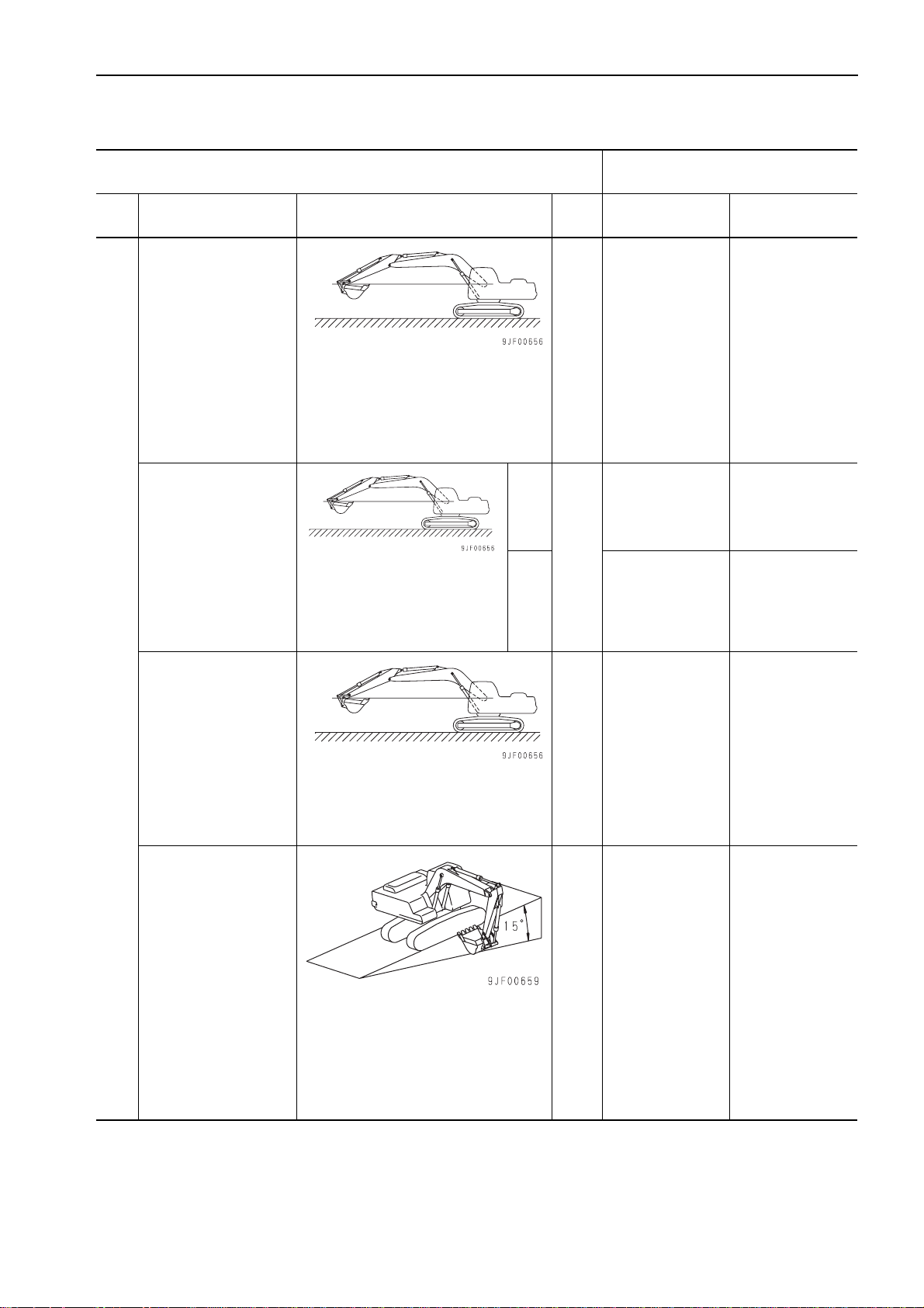
Overrun of swing
Time taken to start
swinging
• Hydraulic oil temperature: 45 – 55 °C
• Engine speed: High idling
• Working mode: A
• Quantity of overrun of swing circle
when it stops after 1 turn
• ( ): Qty of overrun of periphery of
swing circle
90°
• Hydraulic oil temperature:
• Engine speed: High idling
• Working mode: A
• Time taken to swing 90° and
180° after starting
45 – 55 °C
180° 4.0 ± 0.4 Max. 8.5
deg
(mm)
sec
75 ± 10
{730 ± 100}
2.9 ± 0.3 Max. 3.5
Max. 90
(Max. 870)
Swing
Time taken to swing
Hydraulic drift of swing
sec 28.6 ± 4.8 28.6 ± 5.8
• Hydraulic oil temperature: 45 – 55 °C
• Engine speed: High idling
• Working mode: A
• Time taken to swing 5 turns after
swinging 1 turn
mm 0 0
• Hydraulic oil temperature: 45 – 55 °C
• Engine: Stopped
• Set upper structure at 90° to machine
body on slope of 15°.
• Make match marks on inner race and
outer race of swing circle.
• Measure deviation of match marks in
15 minutes.
PC130-7 20-5
(1)
TESTING AND ADJUSTING
STANDARD VALUE TABLE FOR CHASSIS
Model name PC130-7
Cate-
gory
Swing
Travel
Item Measurement condition Unit Standard value Permissible value
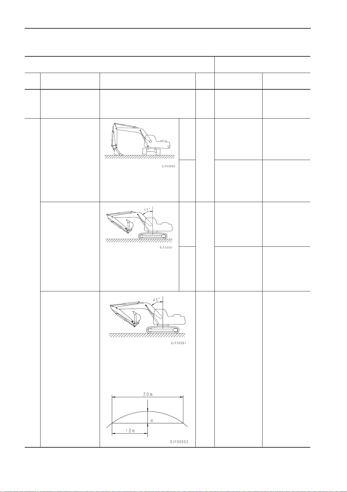
Leakage from swing
motor
Travel speed (Idle run)
Travel speed
(Actual travel)
• Hydraulic oil temperature: 45 – 55 °C
• Engine speed: High idling
• Swing lock switch: LOCK
• Measure leakage for 1 minutes while
swing circuit is relieved.
Lo
• Hydraulic oil temperature:
• Engine speed: High idling
• Working mode: A
• Measure time taken to rotate
track shoe 5 turns after 1 turn.
• Hydraulic oil temperature:
• Engine speed: High idling
• Working mode: A
• Hard and level place
• Measure time taken to travel 20
m after running up 10 m.
45 – 55 °C
45 – 55 °C
Hi 21.9 ± 2.2 23.1 ± 3.0
Lo 27.6 ± 5.1 27.6 ± 7.1
Hi 13.2 ± 1.2 13.2 ± 1.7
l/min Max. 3 Max. 6
46.1 ± 9.2 46.1 ± 9.2
sec
• Hydraulic oil temperature: 45 – 55 °C
• Engine speed: High idling
Travel deviation
• Working mode: A
• Travel speed: Lo
• Hard and level place
• Measure travel deviation in travel of
20 m after running up 10 m.
mm Max. 200 Max. 220
20-6 PC130-7
(1)
TESTING AND ADJUSTING
STANDARD VALUE TABLE FOR CHASSIS
Model name PC130-7
Cate-
gory
Travel
Item Measurement condition Unit Standard value Permissible value
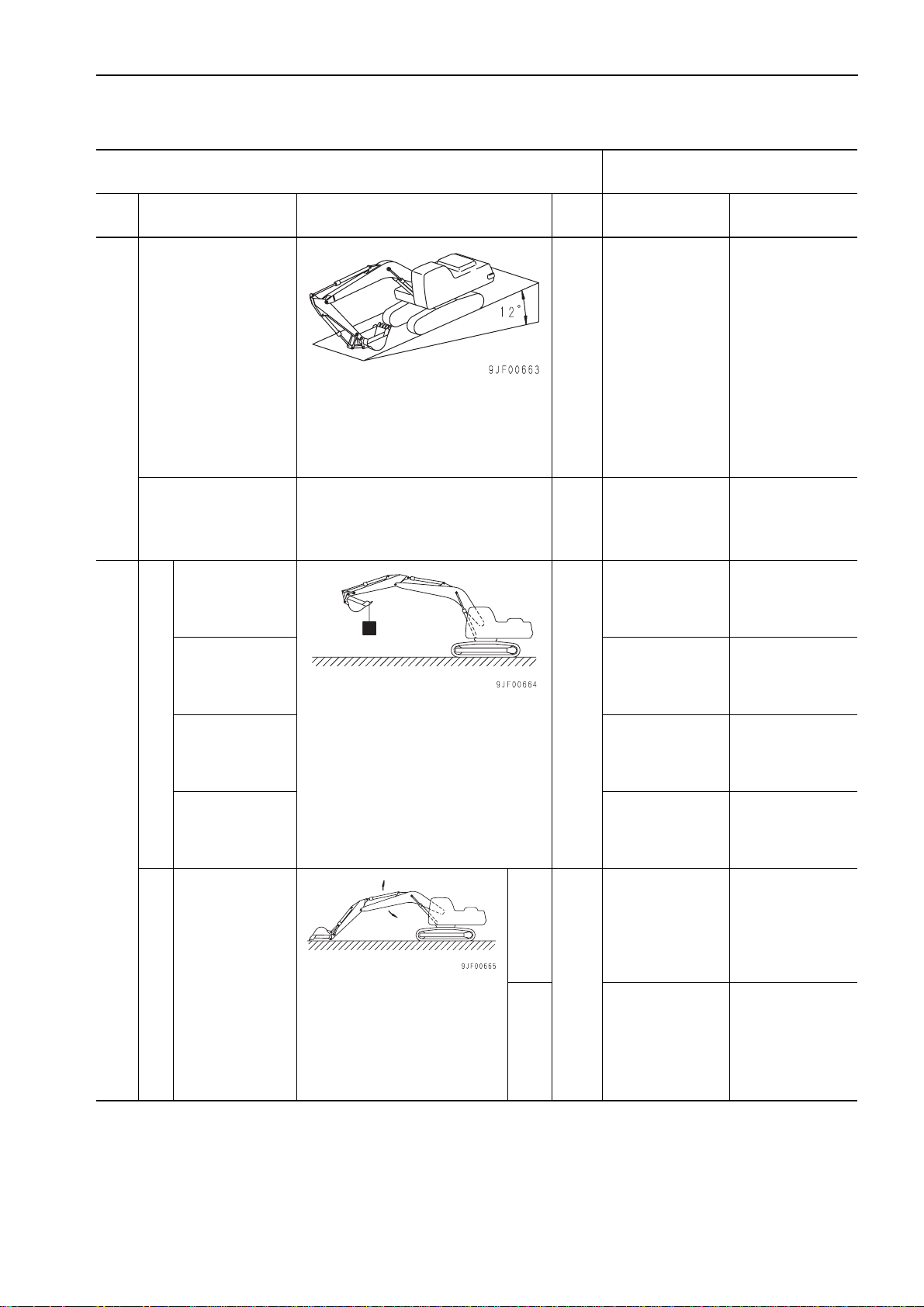
Hydrauli c drift of travel
Leakage from travel
motor
Whole work
equipment
(Hydraulic drift of tooth tip)
• Hydraulic oil temperature: 45 – 55 °C
• Engine: Stopped
• Stop mac hi ne on slope of 12 degrees
with sprocket on upper side.
• Measure hydraulic drift of travel in 5
minutes.
• Hydraulic oil temperature: 45 – 55 °C
• Engine speed: High idling
• Lock sprocket.
• Measure leakage for 1 minutes while
travel circuit is relieved.
mm 0 0
l/min Max. 5 Max. 10
Max. 460 Max. 700
Boom cylinder
(Retraction of cylinder)
• Hydraulic oil temperature: 45 – 55 °C
• Level and flat place
Arm cylinder
(Extension of cylinder)
Hydraulic drift of work equipment
Bucket cylinder
(Retraction of cylinder)
Work equipment
Boom speed
Work equipment speed
• Bucket: Full of dirt and sand or filled
with rated load (1,080 kg)
• Level boom top, retract arm cylinder
fully, and extract bucket cylinder fully.
• Engine: Stopped
• Work equipment con trol lev er: Ne utra l
• Start measuring hy draulic drift just
after setting machine and measure
every 5 minutes for 15 minutes.
RAISE
• Hydraulic oil temperature:
• Engine speed: High idling
• Working mode: A
• Measure time taken to move
bucket between RAISE stroke
end and ground touch point of
bucket.
45 – 55 °C
LOWER
mm
sec
Max. 10 Max. 12
Max. 80 Max. 90
Max. 22 Max. 40
3.7 ± 0.4 Max. 4.3
2.6 ± 0.5 Max. 3.2
PC130-7 20-7
(1)
TESTING AND ADJUSTING
STANDARD VALUE TABLE FOR CHASSIS
Model name PC130-7
Cate-
gory
Work equipment
Item Measurement condition Unit Standard value Permissible value
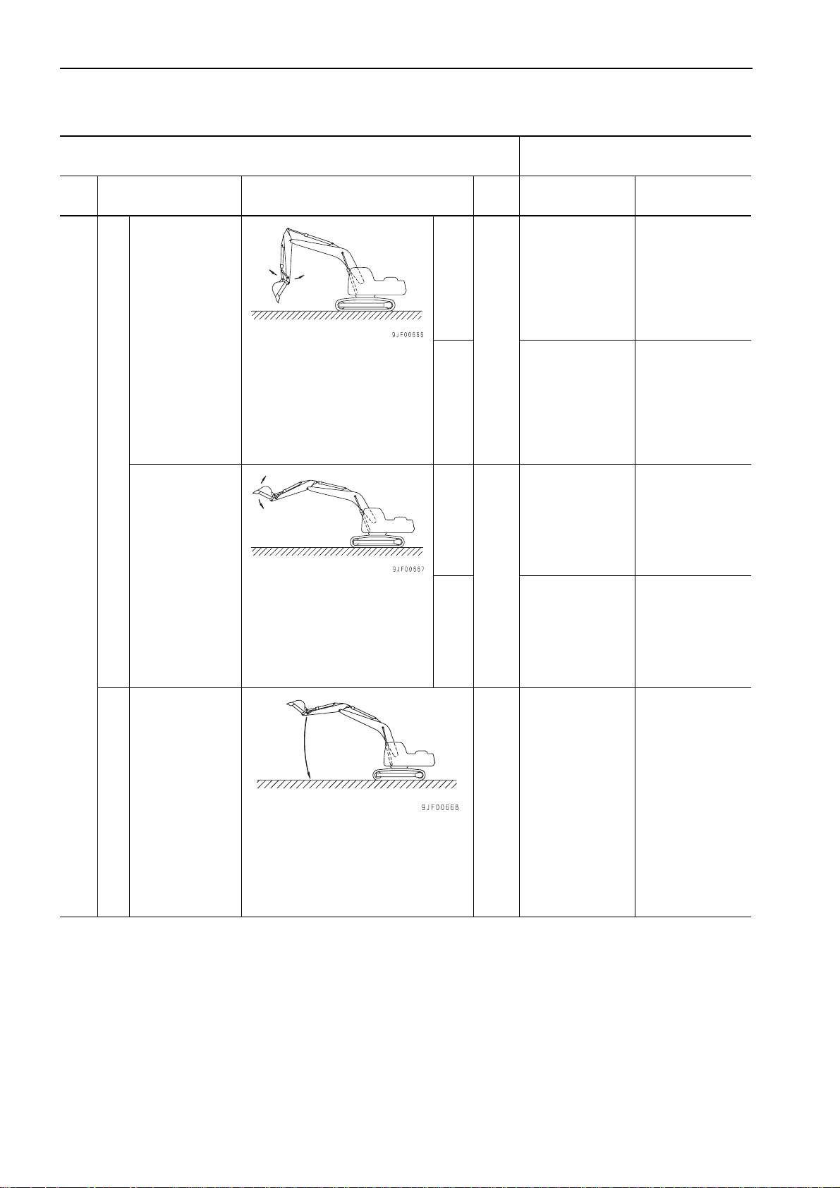
Arm speed
Work equipment speed
Bucket speed
• Hydraulic oil temperature:
45 – 55 °C
• Engine speed: High idling
• Working mode: A
• Measure time taken to move
arm between OUT stroke end
and IN stroke end (between
starting points of cushion).
• Hydraulic oil temperature:
45 – 55 °C
• Engine speed: High idling
• Working mode: A
• Measure time taken to move
bucket between DUMP stroke
end and CURL stroke end
CURL
sec
DUMP
CURL
sec
DUMP
3.2 ± 0.4 Max. 4.4
3.1 ± 0.3 Max. 3.7
2.9 ± 0.3 Max. 3.7
2.3 ± 0.2 Max. 2.9
Boom time lag
Time lag
• Hydraulic oil temperature: 45 – 55 °C
• Engine speed: Low idling
• Working mode: A
• Lower boom from RAISE stroke end
and measure time taken to start raising front of machine after bucket
touches ground.
sec Max. 3.0 Max. 4.0
20-8 PC130-7
(1)
TESTING AND ADJUSTING
STANDARD VALUE TABLE FOR CHASSIS
Model name PC130-7
Cate-
gory
Work equipment
Item Measurement condition Unit Standard value Permissible value
Arm time lag
Time lag
Bucket time lag
Cylinder
Center swivel joint Max. 10 Max. 50
Oil leakage
Travel deviation in
compound operation
of work equipment and
travel
• Hydraulic oil temperature: 45 – 55 °C
• Engine speed: Low idling
• Working mode: A
• Move IN ar m from OUT stroke end
and measure time taken to start moving arm again after it is stopped.
• For measuring posture, see WORK
EQUIPMENT 6.
• Hydraulic oil temperature: 45 – 55 °C
• Engine speed: Low idling
• Working mode: A
• Curl bucket from DUMP stroke end
and measure time taken to start moving bucket again after it is stopped.
• For measuring posture, see WORK
EQUIPMENT 7.
• Hydraulic oil temperature: 45 – 55 °C
• Engine speed: High idling
• Relieve cylinder to be measured or
travel circuit and measure leakage in
1 minute.
• Hydraulic oil temperature: 45 – 55 °C
• Engine speed: High idling
• Working mode: A
• Travel speed: Lo
• Hard and level place
• Measure travel deviation in travel of
20 m after running up 10 m.
sec Max. 2.0 Max. 3.0
sec Max. 2.0 Max. 3.0
Max. 3.5 Max. 15
cc/min
mm Max. 500 Max. 500
Compound operation performanc e
PC130-7 20-9
(1)

TESTING AND ADJUSTING
STANDARD VALUE TABLE FOR CHASSIS
Model name PC130-7
Cate-
gory
PC flow control
Pump
Item Measurement condition Unit Standard value Permissible value
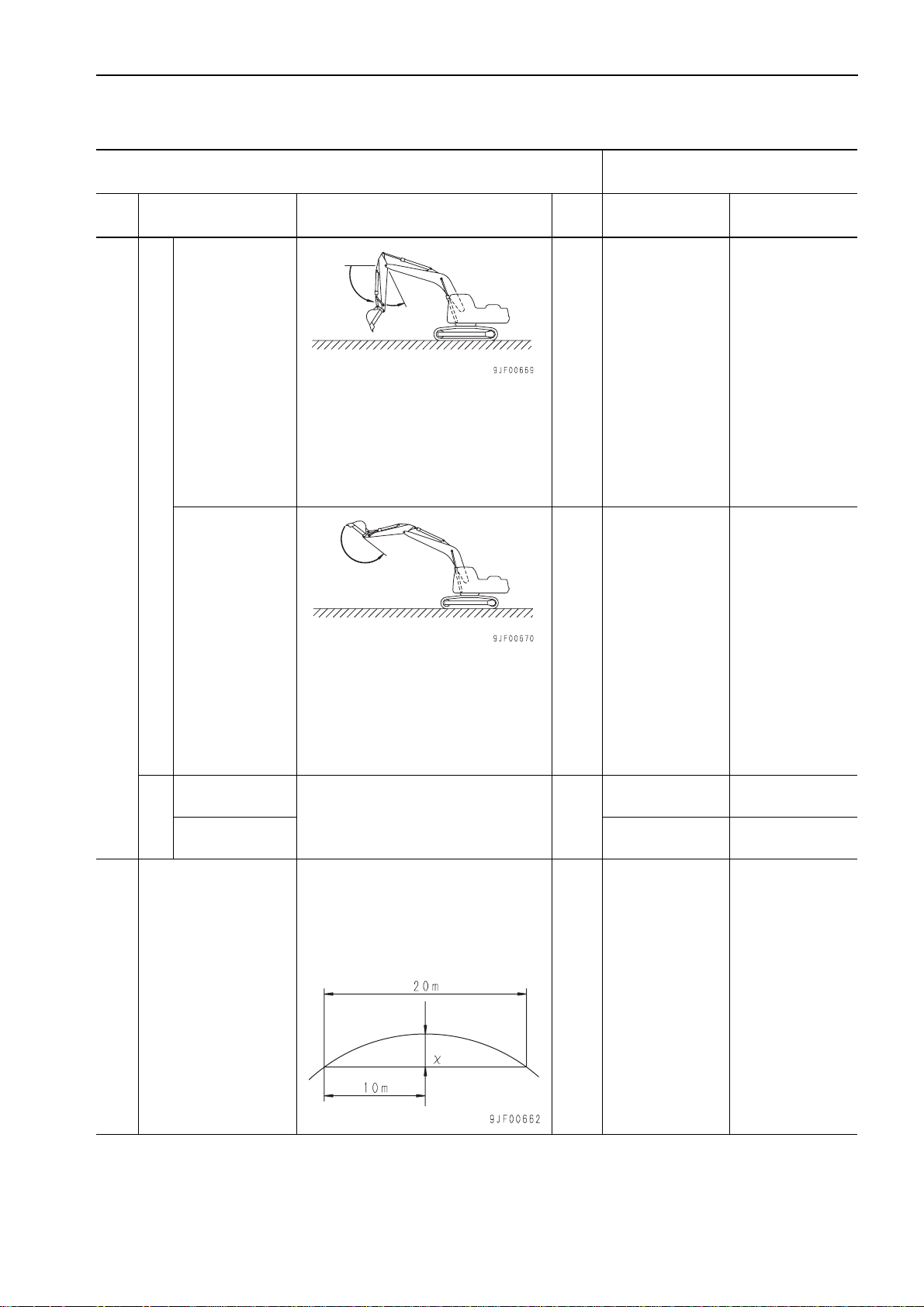
Time taken to swing
90° in compound op eration of raising boom
and starting swinging
characteristics
Hydraulic pump
capacity
performance
• Hydraulic oil temperature: 45 – 55 °C
• Engine: High idling
• Working mode: A
• Bucket: Filled with rated load
• Hard and level place
• Set arm vertically and lower back of
bucket to ground.
• Raise boom and start swinging simultaneously from above posture and
measure time taken to pass 90° point.
• See graph. l/min See graph.
sec
4.0
(Reference value)
20-10 PC130-7
(1)
TESTING AND ADJUSTING
STANDARD VALUE TABLE FOR CHASSIS
Model name PC130-7
Cate-
gory
Item Measurement condition Unit Standard value Permissible value
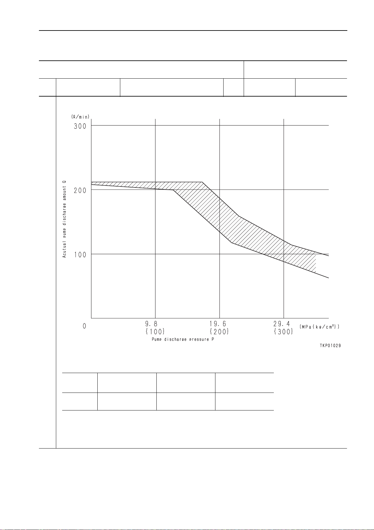
Hydraulic pump performance
Pump performance
• PC-EPC current: 400 mA
• Pump speed: 2,000 rpm
Check point
Any point P
a Avoid measuring near a broken point of the graph, since the error becomes large at that point.
a When measuring without removing the pump from the machine, if the engine speed cannot be set to the speci-
fied speed with the fuel control dial, calc ulate the pump discharge pressure at the specified speed from the
engine speed and pump discharge at the time of measurement.
Test pump discharge
pressure
(MPa{kg/cm2})
Standard discharge
(l/min)
Q
(See graph)
Lower limit of
discharge
(l/min)
Q
(See graph)
PC130-7 20-11
(1)


TESTING AND ADJUSTING
TOOLS FOR TESTING, ADJUSTING, AND TROUBLESHOOTING ......................................................... 20-102
TESTING AND ADJUSTING ENGINE SPEED ..........................................................................................20-104
MEASURING EXHAUST GAS COLOR ....................................................................................... ....... .......20-105
ADJUSTING VALVE CLEARANCE ......... ....... ...... ....... ...... ....... ...... ...... ....... ....................................... ....... 20-107
MEASURING COMPRESSION PRESSURE ............................................................................................. 20-109
MEASURING BLOW-BY PRESSURE ....................................................................................................... 20-110
MEASURING ENGINE OIL PRESSURE ................................................................................................... 20-111
TESTING AND ADJUSTING FOR FUEL INJECTION TIMING ................................................................ 20-112
ADJUSTING ENGINE SPEED SENSOR ....................................... ...... ....... ...... ....... ................................. 20-116
TESTING AND ADJUSTING FAN BELT TENSION .................................................................................. 20-117
TESTING AND ADJUSTING AIR CONDITIONER COMPRESSOR BELT TENSION .............................. 20-118
MEASURING CLEARANCE OF SWING CIRCLE BEARING .................................................................... 20-119
TESTING AND ADJUSTING TRACK SHOE TENSION ............................................................................ 20-120
TESTING AND ADJUSTING OIL PRESSURE IN WORK EQUIPMENT, SWING, AND TRAVEL CIRCUITS
MEASURING CONTROL CIRCUIT BASIC PRESSURE ........................................................................... 20-125
TESTING AND ADJUSTING OIL PRESSURE IN PUMP PC CONTROL CIRCUIT .................................. 20-126
TESTING AND ADJUSTING OIL PRESSURE IN PUMP LS CONTROL CIRCUIT .................................. 20-129
MEASURING SOLENOID VALVE OUTPUT PRESSURE .........................................................................20-133
MEASURING PPC VALVE OUTPUT PRESSURE .................................................................................... 20-135
ADJUSTING PLAY OF WORK EQUIPMENT AND SWING PPC VALVES ............................................... 20-136
TESTING PARTS WHICH CAUSE HYDRAULIC DRIFT OF WORK EQUIPMENT .................................. 20-137
MEASURING OIL LEAKAGE ..................................................................................................................... 20-139
RELEASING RESIDUAL PRESSURE IN HYDRAULIC CIRCUIT ............................................................. 20-142
BLEEDING AIR FROM EACH PART ......................................................................................................... 20-143
TESTING PROCEDURE FOR DIODE ......................................................................................................20-146
SPECIAL FUNCTIONS OF MONITOR PANEL ......................................................................................... 20-147
PREPARATION WORK FOR TROUBLESHOOTING FOR ELECTRIC SYSTEM .................................... 20-166
PM-CLINIC SERVICE................................................................................................................................. 20-167
....... 20-122
PC130-7 20-101
(1)

TESTING AND ADJUSTING
TOOLS FOR TESTING, ADJUSTING, AND TROUBLESHOOTING
TOOLS FOR TESTING, ADJUSTING, AND TROUBLESHOOTING
Testing and adjusting item
Measuring exhaust gas
color
Adjusting valve clearance
Measuring compression
pressure
Measuring blow-by pressure
Measuring engine oil pressure
Part No. Part name
Symbol
1 799-203-9000
A
Commercially
2
available
Commercially
B
available
795-502-1205 Compres sion gauge 1 0 – 6.9MPa {0 – 70kg/cm2}
C
795-502-1370 Adapter 1
6204-11-3880 Gasket 1
D
799-201-1504 Blow-by checker 1 —
799-101-5002 Hydraulic tester 1
1
790-261-1203
E
2 799-401-2320 Hydraulic tester 1 Pressure gauge: 0.98MPa {10kg/cm
3
799-401-3500 Adapter 1 Size: 06
799-101-5220 Nipple 1
4
07002-11023 O-ring 1
Handy smoke
checker
Smoke meter 1
Feeler gauge 1
Digital hydraulic
tester
Q'ty
1
Pollution level: 0 – 70% (With standard
color)
(Pollution level x 1/10 C Bosch index)
(Air intake side: 0.35 mm, Exhaust side:
0.50 mm)
For 95E-3 engine
Pressure gauge: 2.5,5.9,39.2,58.8MPa
1 Pressure gauge: 58.8MPa {600kg/cm
Size: 10 x 1.25mm
Remarks
{25,60,400,600kg/cm
2
}
2
}
2
}
Measuring fuel injection
timing
Measuring clearanc e of
swing circle bearing
Testing and adjusting oil
pressure in work equipment, swing, and travel circuits
Measuring control circuit
basic pressure
Testing and adjusting oil
pressure in pump PC control circuit
1
795-102-2103 Spring pusher 1
F
Commercially
2
available
Commercially
G
available Dial gauge 1 —
799-101-5002 Hydraulic tester 1
1
790-261-1203
H
799-101-5220 Nipple 1
2
07002-11023 O-ring 1
799-101-5002 Hydraulic tester 1
1
790-261-1203
J
799-101-5230 Nipple 1
2
07002-11423 O-ring 1
799-101-5002 Hydraulic tester 1
1
790-261-1203
K
799-101-5230 Nipple 2
2
07002-11423 O-ring 2
Dial gauge 1
Digital hydraulic
tester
Digital hydraulic
tester
Digital hydraulic
tester
For deliver y valve method
* Same as E1
1
* Same as E4
* Same as E1
1
Size: 14 x 1.5mm
1
* Same as H ( Only quantity is different)
20-102 PC130-7
(1)

TESTING AND ADJUSTING
TOOLS FOR TESTING, ADJUSTING, AND TROUBLESHOOTING
Testing and adjusting item
Testing and adjusting oil
pressure in pump LS control circuit
Measuring s olenoid valv e
output pressure
Measuring PPC valve output pressur e
Measuring oil leakage
Measuring water temperature and oil temperature
Part No. Part name
Symbol
799-101-5002 Hydraulic tester 1
1
790-261-1203
L
799-101-5230 Nipple 2
2
07002-11423 O-ring 2
3
799-401-2701
799-101-5002 Hydraulic tester 1
1
M
790-261-1203
2
799-401-3100 Adapter 1 Size: 03
799-101-5002 Hydraulic tester 1
1
N
790-261-1203
2
799-401-3100 Adapter 1 * Same as M2
Commercially
P
available
—
799-101-1502 Digital thermometer 1 -99.9 – 1,299°C
Digital hydraulic
tester
Differential pressure
gauge
Digital hydraulic
tester
Digital hydraulic
tester
Measuring cylinder 1
Q'ty
1
* Same as H (Only quantity is different)
1—
* Same as E1
1
* Same as E1
1
Remarks
Measuring operating effort
and pressing force
Measuring stroke and
hydraulic drift
Measuring work equipment
speed
Measuring voltage and
resistance
79A-264-0021 Push-pull scale 1 0 – 294N {0 – 30kg}
—
79A-264-0091 Push-pull scale 1 0 – 490N {0 – 50kg}
Commercially
—
available
Commercially
—
available
Commercially
—
available
Scale 1 —
Stopwatch 1 —
Circuit tester 1 —
a For the model names and part Nos. of the T-adapters and boxes u sed for troubleshooting for the monitor
panel, controllers, se nso r s, act uators, and wiring h ar nes se s, se e T RO UB LE SHO O TING, Layout of connectors and electric circuit diagram of each system.
PC130-7 20-103
(1)
TESTING AND ADJUSTING
TESTING AND ADJUSTING ENGINE SPEED
TESTING AND ADJUSTING
ENGINE SPEED
MEASURING
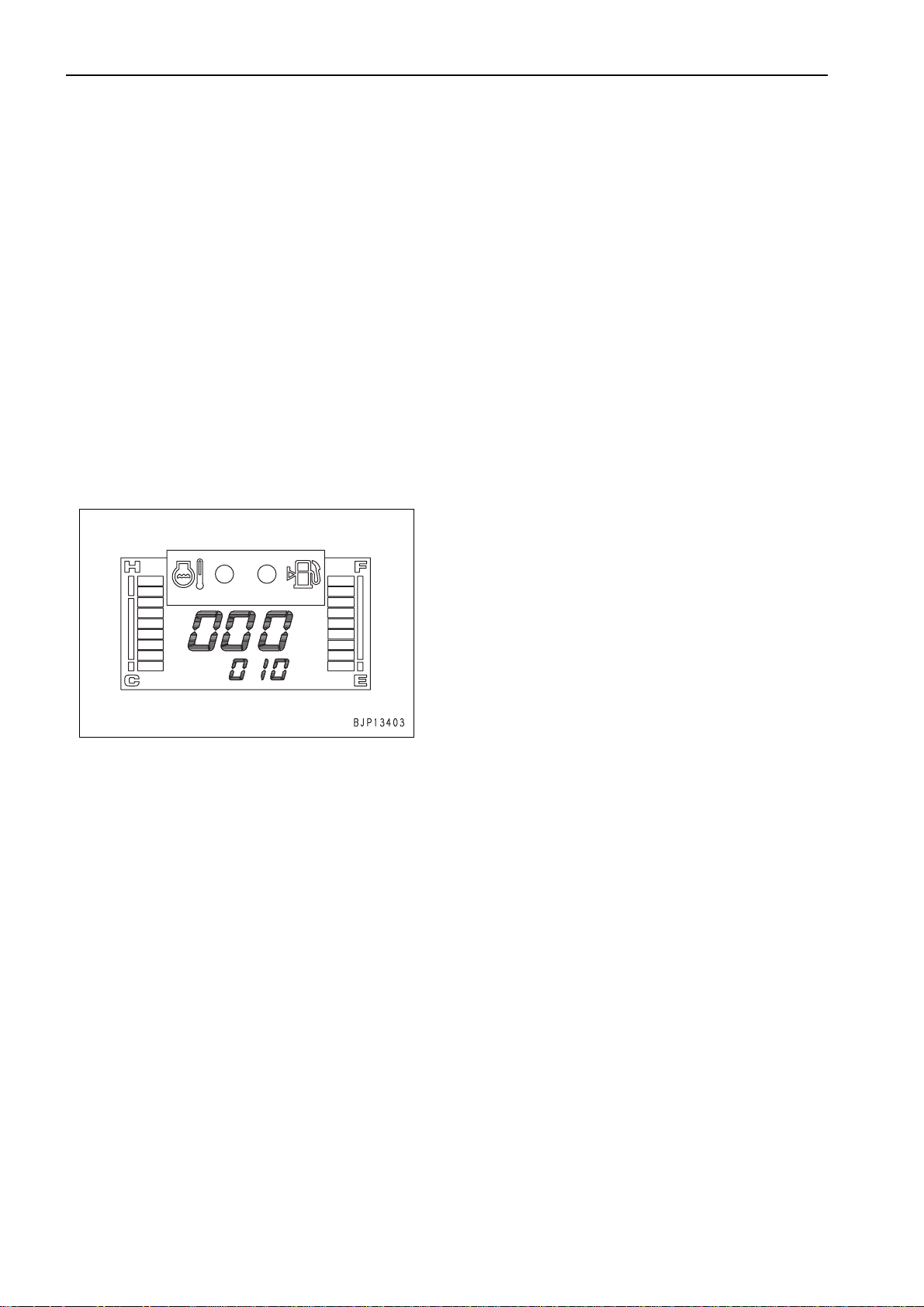
1. Preparation work
1) Turn the starting switch ON and set the monitor panel in the "Monitoring func tion [02]" to
prepare for measurement of the engine
speed.
a For the operating method, see "Special
functions of monitor panel".
• Monitoring code: 010 (Engine speed)
a The engine speed is displayed in rpm.
2) Warm up the engine to the following o perating condition.
• Engine coolant temperature: Within oper-
ating range
• Hydraulic oil temperature: 45 – 55°C
a Measure the engine speed with the work-
ing mode switch in the A-mode position.
4. Measuring pump relief and one-touch power
maximizing speed
1) Set the fuel control dial in the high idling
(MAX) position.
2) Relieve the arm circuit by moving the arm IN,
keeping pressing the one-touc h power max imizing switch, and measure the engine
speed.
a The one-touch power maximizing func-
tion is reset automatically in about 8.5
seconds even if the switch is kept held.
Accordingly, measure the engine speed
in that period.
5. Measuring auto-deceleration speed
1) Start the engine and set the fuel contr ol dial
in the high idling position (MAX).
2) Set the work equip ment control, swing con-
trol, and travel levers in n eutr a l an d me as ure
the engine speed.
a The engine speed lowers to a certain
level about 5 seconds after all the levers
are set in neutral. This level is the autodeceleration speed.
1. Measuring low idling speed
1) Set the fuel contr ol dial in t he low idli ng (M IN)
position.
2) Set the work equipment control, swing control, and travel levers in neu tr al a nd m eas ure
the engine speed.
2. Measuring high idling speed
1) Turn the auto-decelerator switch OFF.
2) Set the fuel control dial in the high idling
(MAX) position.
3) Set the wo rk equipment control, swing control, and travel levers in neu tr al a nd m eas ure
the engine speed.
ADJUSTING
Adjusting governor spring
a If the high idling speed is out of the standard
range or the engine speed is unstable (the
engine hunts), adjust the governor spring with
"Governor adjustment function [03]" of the monitor panel.
a For the adjustment procedure, see SPECIAL
FUNCTIONS OF MONITOR PANEL.
3. Measuring pump relief speed
1) Set the fuel control dial in the high idling
(MAX) position.
2) Relieve the arm circui t by mo ving the a rm IN
and measure the engine speed.
20-104 PC130-7
(1)
TESTING AND ADJUSTING
MEASURING EXHAUST GAS COLOR
MEASURING EXHAUST GAS
COLOR
a Measuring instruments for exhaust gas color
Symbol Part No. Part name
1 799-201-9000 Handy Smoke Checker
A
k When installing and removing the measuring
a If an air source and an el ec tric p ower source are
not available in the field, use handy smo ke
checker A1. When recording official data, use
smoke meter A2.
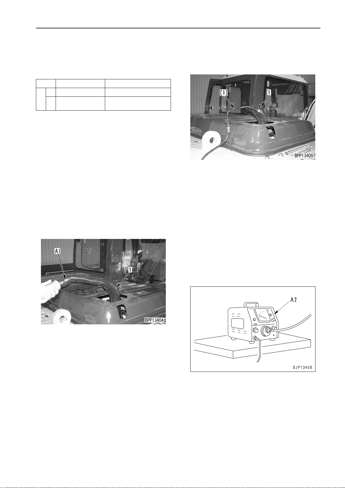
1. Measuring with handy smoke checker A1
1) Stick a sheet of filter paper to smoke checker
2) Insert the exhaust gas intake pipe in exhaust
3) Run the engine.
4) Accelerate the engine suddenly or run it at
Commercially
2
instruments, take care not to touch a hot part.
available
A1.
pipe (1).
high idling and operate the han dle of smoke
checker A1 so that the filter paper will absorb
the exhaust gas.
Smoke Meter
2. Measuring with smoke meter A2
1) Insert probe [1] of smoke meter A2 in the
outlet of exhaust pipe (1) and fix it to the
exhaust pipe with a clip.
2) Connect the probe hose, receptacle of the
accelerator switch, and air hose to smoke
meter A2.
a Limit the supplied air pressure to 1.5
MPa {15 kg/cm
3) Connect the p ower cable to a receptacle of
AC 100 V.
a Before connecting the cable, chec k that
the power switch of the smoke meter is
turned OFF.
4) Loosen the cap nut of the sucti on pump and
fit the filter paper.
a Fit the filter paper securely so that the
exhaust gas will not leak.
5) Turn on the power switch of smoke meter
A2.
2
}.
5) Remove the filter paper and compare it with
the attached scale.
6) After finishing measurement, remove the
measuring instrument and return the
removed parts.
6) Start the engine and heighten the engine
coolant temperature to the operating range.
PC130-7 20-105
(1)

TESTING AND ADJUSTING
7) Accelerate the engine suddenly or run it at
high idling and press the accelerator pedal of
smoke meter A2 and co llect the exhau st ga s
into the filter paper.
8) Place the contaminated filter paper on the
clean filter paper (at least 10 sheets) in the
filter paper holder and read the indicated
value.
9) After finishing measurement, remove the
measuring instrument and return the
removed parts.
MEASURING EXHAUST GAS COLOR
20-106 PC130-7
(1)
TESTING AND ADJUSTING
ADJUSTING VALVE CLEARANCE
ADJUSTING VALVE
CLEARANCE
a Adjusting instrument for valve clearance
Symbol Part No. Part name
B
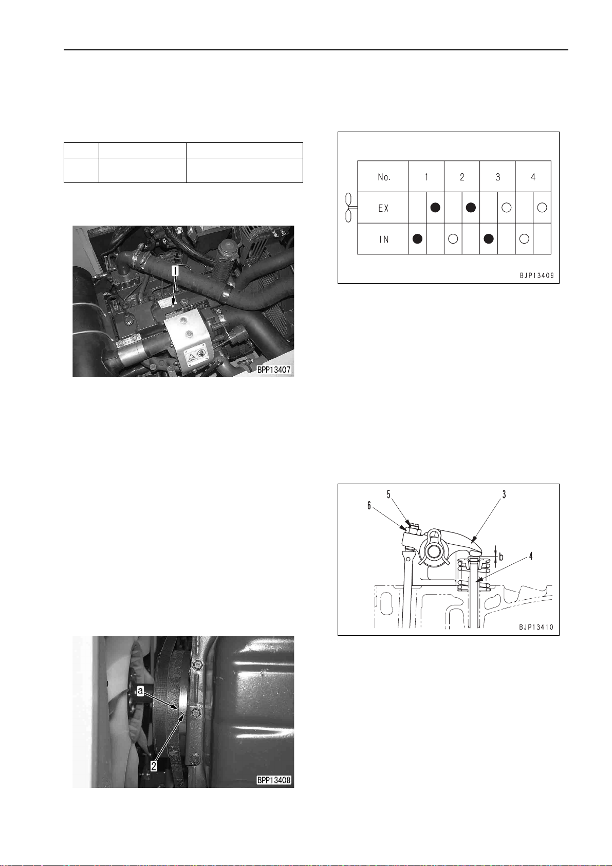
1. Open the engine hood and remove all cylinder
head covers (1).
2. Remove the engine unde rcover (on the radiator
side).
3. Rotate the crankshaft forward to bring the
stamped "1.4TOP" line (a) of the crank p ulley to
pointer (2) and set the N o. 1 c yli nde r to the compression top dead center.
a Crank the crankshaft with the crank pulley
a There are 2 stamped "1.4TOP" lines on the
a When the No. 1 cylinder is at the c ompres-
Commercially
available
mounting bolt.
crank pulley. Use the one at the diagonal
position of "2.3TOP".
sion top dead center, the rocker arm of the
No. 1 cylinder can be moved by the valve
clearance with the hand. If the rocker arm
cannot be moved, the No. 1 cyl in der is not at
the compression top dead center. In th is
case, rotate the crankshaft one more turn.
Feeler gauger
4. While the No. 1 cylinder is at the compression
top dead center, adjust the valve clearances
marked with q in the valve arran gem ent dr awi ng
according to the following procedure.
1) Insert feeler gauge B in clearance (b)
between rocker arm (3) and valve stem (4)
and adjust the clearance with adjustment
screw (5).
a With the feeler gauge inserted, turn the
adjustment screw to a degree that you
can move the filler gauge lightly.
2) Secure adjustment screw (5) and tighten
locknut (6).
3 Locknut: 39.2 – 49 Nm {4 – 5 kgm}
a After tightening the locknut, check the
valve clearance again.
a After adjusting all of the valves marked
with q, go to the next procedure.
5. Rotate the crankshaft forward to bring the
stamped "1.4TOP" line (a) of t he crank pulley to
pointer (2) and set the No . 4 c ylin der to t he c ompression top dead center.
PC130-7 20-107
(1)

TESTING AND ADJUSTING
6. While the No. 4 cylinder is at the compression
top dead center, adjust the valve clearances
marked with Q in the valve arrangement drawing.
a Adjust the valve clearance acc ording to st ep
4 above.
7. After finishing adjustment, return the removed
parts.
3 Cylinder head cover mounting bolt:
7.84 – 9.8 Nm {0.8 – 1.0 kgm}
ADJUSTING VALVE CLEARANCE
20-108 PC130-7
(1)
TESTING AND ADJUSTING
MEASURING COMPRESSION
PRESSURE
a Measuring instruments for compression pressure
Symbol Part No. Part name
795-502-1205 Compression gauge
C
a When measuring the compression pressure,
take care not to burn yourself on the exhaust
manifold, muffler, etc. or get caught in a rota ting
part.
1. Adjust the valve clearance.
a See Adjusting valve clearance.
2. Warm up the engine until the engine oil temperature is 40 – 60°C.
795-502-1370 Adapter
6204-11-3880 Gasket
MEASURING COMPRESSION PRESSURE
6. Remove governor spring (2).
7. Put governor l ever (3) of the fuel injection pump
to the STOP side stopper and fix it.
3. Prepare for measuring the engine speed.
a See Testing and adjusting engine speed.
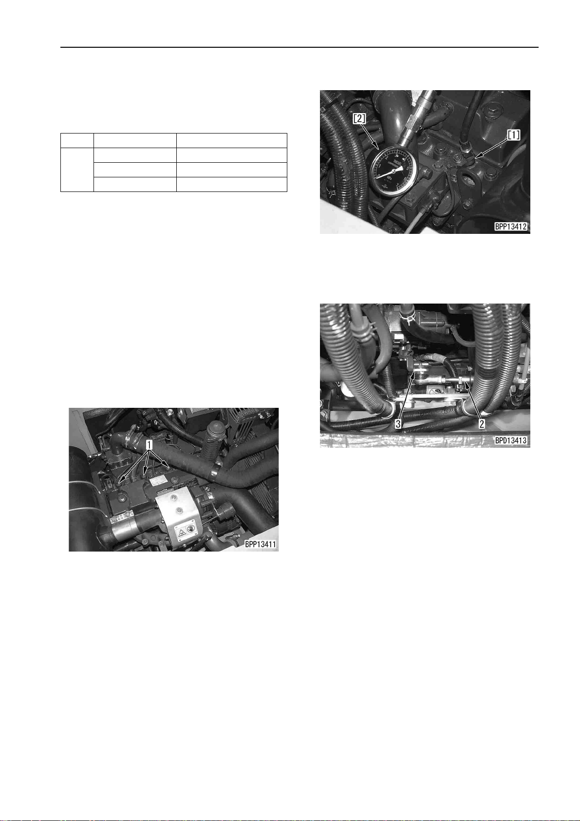
4. Open the engine hood and remove nozzle holder
(1) of the cylinder to measure the compression
pressure.
5. Install adapter [1] of compression gauge C to the
mounting part of the nozzle ho lder and connect
gauge [2].
a Install the gasket to the end of the adapter.
a Secure the adapter with the clamping holder
and mounting bolt for the nozzle holder.
3 Mounting bolt: 39.2 – 49 Nm {4 – 5 kgm}
8. Crank the engine with the starting motor and
measure the compression pressure.
a Read the compression gauge when its
pointer is stabilized.
a When measuring the compression pr essure,
measure the engine speed, too, and check
that it is in the measurement condition range.
9. After finishing measurement, remove the measuring instruments and return the removed parts.
a Check that the fulcrum of the clamping
holder for the nozzle holder is seated on the
cylinder head, and then ti ghten th e mounti ng
bolt.
3 Mounting bolt: 39.2 – 49 Nm {4 – 5 kgm}
PC130-7 20-109
(1)
TESTING AND ADJUSTING
MEASURING BLOW-BY PRESSURE
MEASURING BLOW-BY
PRESSURE
a Measuring instruments for blow-by pressure
Symbol Part No. Part name
D 799-201-1504 Blow-by checker
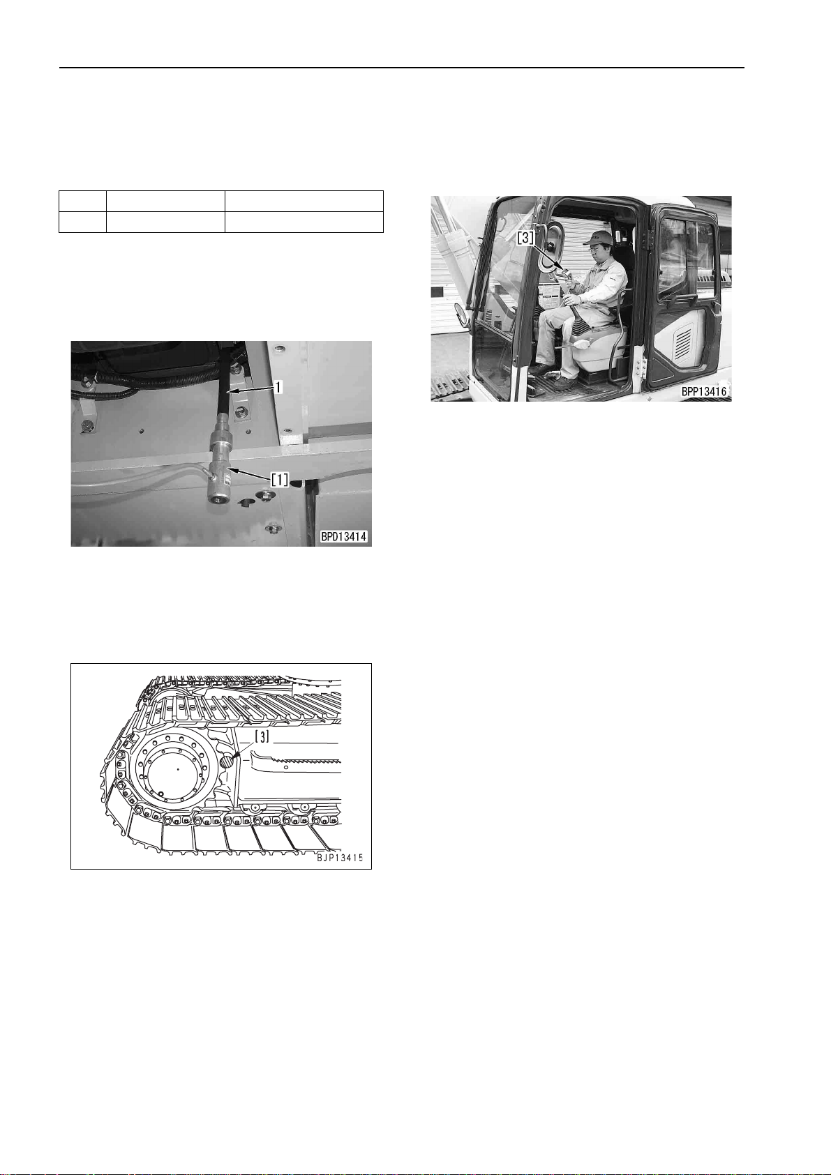
1. Remove the engine und ercover (on the flywhee l
side).
2. Install nozzle [1] of blow- by che ck er C to the end
of blow-by hose (1) and connect it to gauge [2].
5. Run the engine at high idling and measure the
blow-by pressure .
• Working mode: A
• Work equipment, swing, and travel circuit:
Relieve the travel circuit.
6. After finishing measurement, remove the measuring instruments and return the removed parts.
3. Start the engine and lock the travel mechanism.
k Put pin [3] between the sprocket and track
frame to lock the travel mechanism
securely.
4. Start the engine and warm it up to t he operating
range.
• Engine coolant temperature: Within operat-
ing range
• Hydraulic oil temperature: 45 – 55°C
20-110 PC130-7
(1)
TESTING AND ADJUSTING
MEASURING ENGINE OIL PRESSURE
MEASURING ENGINE OIL
PRESSURE
a Measuring instruments for engine oil pressure
Symbol Part No. Part name
799-101-5002 Hydraulic tester
1
790-261-1203 Digital hydraulic tester
2 799-401-2320 Hydraulic tester
E
3 799-401-3500 Adapter (Size: 06)
799-101-5220 Nipple (10 x 1.25 mm)
4
07002-11023 O-ring
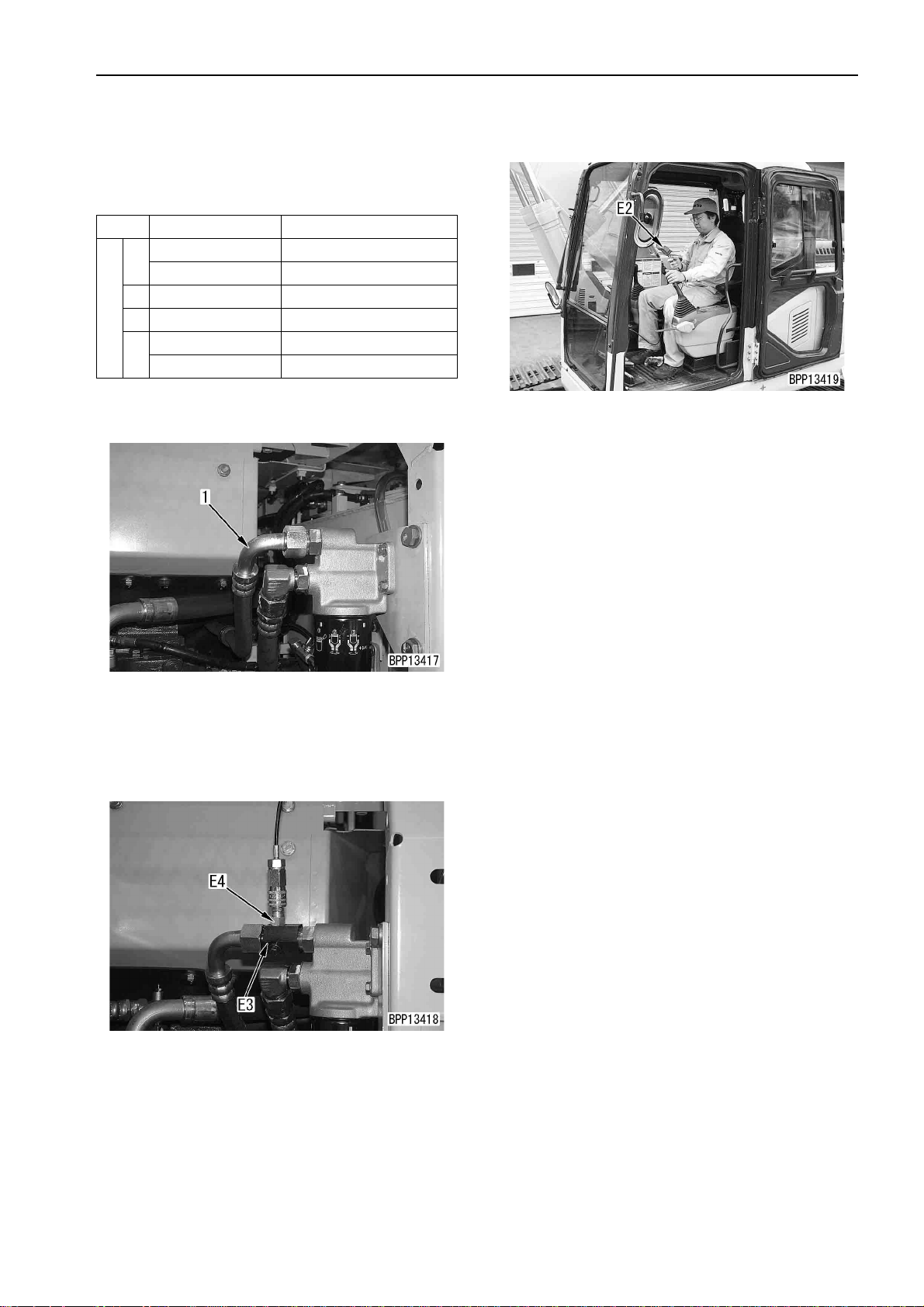
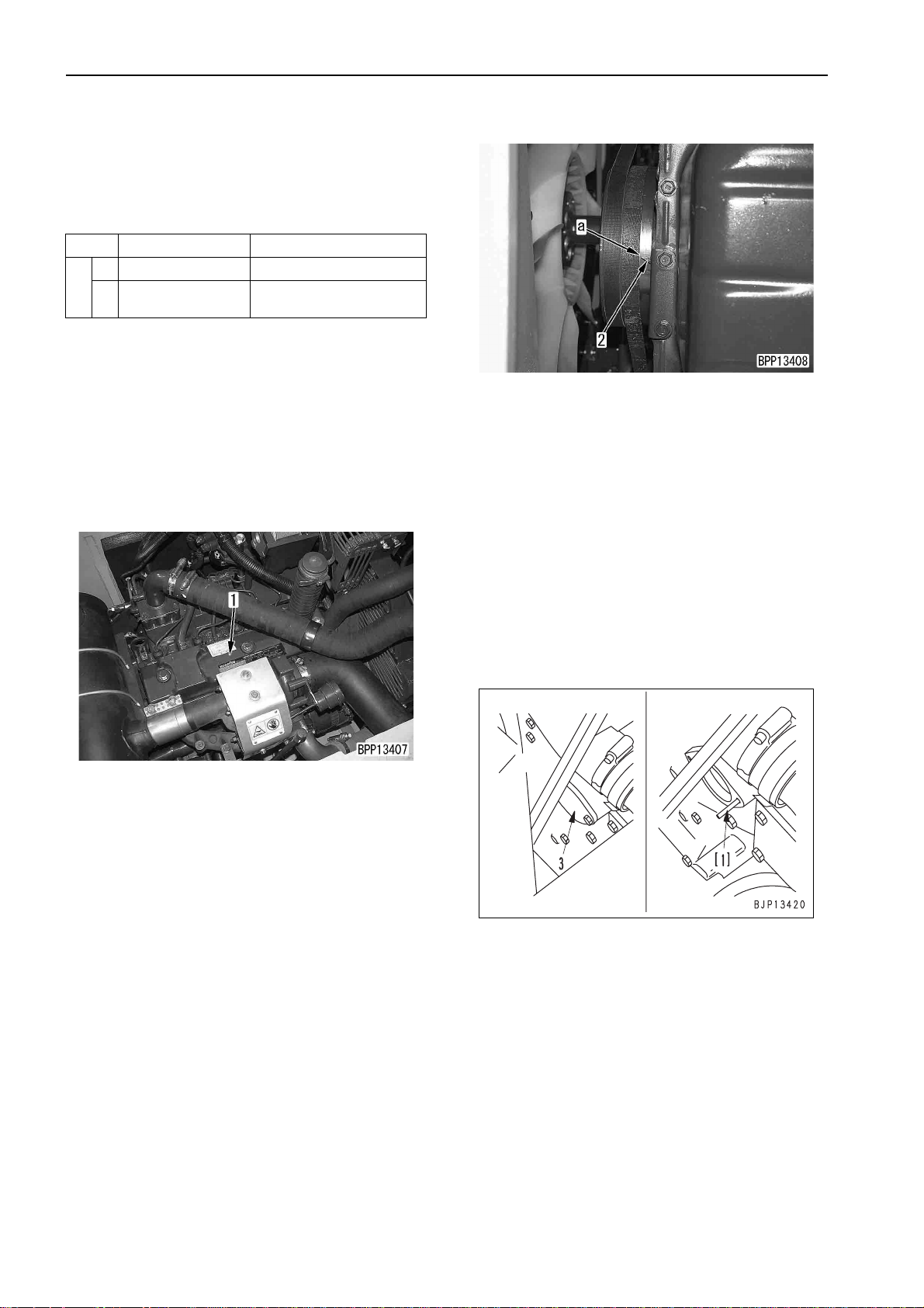
1. Open the pump room cover and disconnect outlet hose (1) of the engine oil filter.
5. Measure the oil pressure during low idling and
high idling.
6. After finishing measurement, remove the measuring instruments and return the removed parts.
2. Install adapter E3 and conne ct the di sconnec ted
hose again.
3. Install nipple E4 and connect it to hydraulic tester
E2.
4. Start the engine and heighten the engine coolant
temperature to the operating range.
PC130-7 20-111
(1)
TESTING AND ADJUSTING
TESTING AND ADJUSTING FOR FUEL INJECTION TIMING
TESTING AND ADJUSTING
FOR FUEL INJECTION TIMING
a Testing and adju sting instruments for fuel injec-
tion timing (for delivery valve method)
Symbol Part No. Part name
1 795-102-2103 Spring pusher
F
TESTING AND ADJUSTING BY MATCH MARK
METHOD
a After removing and installing the fuel injection
pump without repairing it or when only checking
the injection timing, test and adjust the injection
timing according to the following procedure.
2
Commercially
available
Dial gauge
4. Remove cover (3) of the fuel injection pump
drive shaft.
TESTING
1. Open the engine hood and remove all cylinder
head covers (1).
2. Remove the engine under cover (on the radiator
side).
3. Rotate the crankshaft forward to bring the
stamped "1.4TOP" line (a) of the crank pulley to
pointer (2) and set the No. 1 cyl inder to th e c ompression top dead center.
a Crank the crankshaft with the crank pulley
mounting bolt.
a There are 2 stamped "1.4TOP" lines on t he
crank pulley. Use the one at the diagonal
position of "2.3TOP".
a When the No. 1 cylinder is at the compres-
sion top dead center, the rocker arm of the
No. 1 cylinder can be moved by the valve
clearance with the han d. If the rocker arm
cannot be moved, the No. 1 cy li nde r is no t at
the compression top dead center. In this
case, rotate the crankshaft one more turn.
5. Insert pin [1] in the mounting bolt hole of the front
cover (on the outside of the engi ne) to chec k the
fuel injection timing.
a Use a pin 4.0 – 4.5 mm in diameter and
about 80 mm in length.
a If the pin enters smoothly to inside of the
drive gear of the fuel injection pump, the fuel
injection timing is normal. In this case, return
the removed parts.
a If the pin touches the drive gear of the fuel
pump, the fuel injection timing is abnormal.
In this case, adjust the fuel injection timing.
ADJUSTING
a If the fuel injection timing is abnormal, adjust it
according to the following procedure.
1. Remove the fuel pump, holder, and drive gear
together.
a See DISASSEMBLY AND ASSEMBLY,
Removal, installation of fuel pump assembly.
20-112 PC130-7
(1)

TESTING AND ADJUSTING
TESTING AND ADJUSTING FOR FUEL INJECTION TIMING
2. Remove bolt (3) and fix drive gear (4) to holder
(5) with fixing bolt [2].
a As fixing bolt [2], use a bolt 6 mm in t hread
diameter and 35 mm in length.
a Pass the fixing bolt through the screw hole of
bolt (3) and tighten it into the screw hole of
the drive gear, and the fuel injec tion pump is
fixed in the fuel injection timing.
3. Install the fuel inje ction pump, holder, and drive
gear together.
a See DISASSEMBLY AND ASSEMBLY,
Removal, installation of fuel pu mp assembly.
a Af te r i ns talling the fuel injection pump tempo-
rarily, check the fuel injection timing according to the above described procedure.
4. After finishing adjustment, remove the measuring tools and return the removed parts.
k Be sure to remove pin [1] and fixing bolt [2].
3 Cylinder head cover mounting bolt:
7.84 – 9.8 Nm {0.8 – 1.0 kgm}
ADJUSTING BY DELIVERY VALVE METHOD
a After repairing or replacing the fuel injection
pump or timing gear, adjust the injection timing
according to the following procedure.
ADJUSTING
a Apply the delivery valv e method to only adjust-
ment of the injection timing.
1. Open the engine hood and remove all cylinder
head covers (1).
2. Remove the engine under cover (on the radiator
side).
3. Rotate the crankshaft forward to bring the
stamped "1.4TOP" line (a) of t he crank pulley to
pointer (2) and set the No . 1 c ylin der to t he c ompression top dead center.
a Crank the crankshaft with the crank pulley
mounting bolt.
a There are 2 stamped "1.4TOP" lines on t he
crank pulley. Use the one at the diagonal
position of "2.3TOP".
a When the No. 1 cylinder is at the compres-
sion top dead center, the rocker arm of the
No. 1 cylinder can be moved by the valve
clearance with the hand. If the rocker arm
cannot be moved, the No. 1 cy lind er is n ot at
the compression top dead center. In this
case, rotate the crankshaft one more turn.
PC130-7 20-113
(1)

TESTING AND ADJUSTING
TESTING AND ADJUSTING FOR FUEL INJECTION TIMING
4. Remove snap ring (6 ) of the rocker arm shaft on
the No. 1 cylinder side , and then remove rocker
arm (7) of the No. 1 air intake valve.
a Remove the valve stem cap, too.
5. Using spring pusher F1, remove v alve cotter (8)
of the No. 1 air intake valve.
6. Loosen spring pusher F1 and remove seat (9)
and spring (10).
8. Install dial gauge F2 on the valve stem of No. 1
air intake valve (11) and set it to the 0 point.
a Since the No. 1 cylinder is at the compres-
sion top dead center, set this point as th e 0
point.
9. Rotate the crankshaft about 45° in reverse.
10. Rotate the crankshaft forward slowly so tha t dial
gauge F2 will indicate fuel injection timing dimension (a).
a When adjusting the crankshaft to fuel injec-
tion timing dimen sion ( a), be sure to rotat e it
forward so that the adjustme nt will not be
affected by the backlash of the drive gear. (If
the crankshaft passes the adjustment dimension, return it sufficiently, and then adjust it
again forward.)
a Fuel injection timing dimension (a) and fuel
injection timing
Fuel injection timing
dimension (a)
Fuel injection timing
(Reference)
mm 0.42 ± 0.08
°6 ± 0.75
7. While No. 1 air intake valve (11) is in contact with
the top of piston (12), turn the valve stem with
the hand to press No. 1 air intake valve (11)
against the piston.
a Since the piston stroke will be meas ured at
11. Disconnect all of co nnected fuel injection tubes
(12), if there are any.
the valve stem top, check that the valve bottom is in contact with the piston top securely.
20-114 PC130-7
(1)

TESTING AND ADJUSTING
TESTING AND ADJUSTING FOR FUEL INJECTION TIMING
12. Remove delivery valve holder (14) for the No. 1
cylinder of fuel pump (13), delivery valve (15),
and spring (16), and then install delivery valve
holder (14) again.
13. Remove governor spring (1 7), and then put the
governor lever ( 18) of the fuel inj ection pump to
the stopper on the FULL side and fix it.
14. Remove the fixing bracket and lubrication tube of
fuel injection pump ( 13), loosen 4 mounting nuts
(19), and lean the fuel injection pump outward
fully.
a Loosen the mounting nuts to a degree that
the fuel injection pump can be moved in and
out within the range of the oblong hole (Do
not loosen them so much that the fuel injection pump will have play).
16. Tighten 4 mounting nuts (19) of fuel injection
pump (13) securely and alternately.
17. After finishing a djustment, remove the adjusting
tools and return the removed parts.
a Replace the O-ring and copper gasket of the
delivery valve with new ones.
k Tighten the delivery valve securely in 3
times. (If it is not tightened sufficient ly, the
gasket may be broken.)
3 Delivery valve holder:
39.2 – 44.1 Nm {4 – 4.5 kgm}
3 Fuel injection tube sleeve nut:
19.6 – 24.5 Nm {2 – 2.5 kgm}
3 Cylinder head cover mounting bolt:
7.84 – 9.8 Nm {0.8 – 1.0 kgm}
a After finishing adjustment, if the stamped
lines of the fuel injection pump and holder
are not at the same position or there is not a
stamped line on the fuel injection pump,
stamp a new line to show that the fuel injection timing has been adjusted.
15. Operating priming pump (20) of fuel injection
pump 13, move the injection pump gradually
toward the cylinder block and stop when the fuel
stops flowing out of No. 1 del ivery valve holder
(14), and then tighten the mounting nuts tempo rarily.
a The position where fuel stops flowing out of
the No. 1 delivery valve holder is the position
to start fuel injection in the No. 1 c ylinder
(fuel injection timing).
PC130-7 20-115
(1)

TESTING AND ADJUSTING
ADJUSTING ENGINE SPEED SENSOR
ADJUSTING ENGINE SPEED
SENSOR
a If the engine speed sensor has been removed
and installed or its signal contains an error,
adjust it according to the following procedure.
a Remove engine speed sensor ( 1) before adju st-
ing it and check that its tip is free from steel chips
(The engine speed sensor is installed to the right
side of the flywheel housing).
4. After finishing adjustment, check that the monitor
panel displays the en gine speed normally in the
"Monitoring mode".
a For the operating method, see "Special func-
tions of monitor panel".
• Monitoring code: 010 (Engine speed)
1. Screw in senso r (1) until its tip touches the too th
tip of flywheel ring gear (2).
2 Threads: Gasket sealant (LG-6)
2. Return sensor (1) by the specified angle.
a Returning angle of sensor: 1 ± 1/6 turn
a After this adjustment, clearance (a) b etween
the sensor tip and gear tooth tip is 1.25 –
1.75 mm.
3. Fixing sensor (1), tighten nut (3).
2 Nut: 49 – 68.6 Nm {5 – 7 kgm}
20-116 PC130-7
(1)

TESTING AND ADJUSTING
TESTING AND ADJUSTING FAN BELT TENSION
TESTING AND ADJUSTING
FAN BELT TENSION
TESTING
1. Open the engine hood and remove the belt cover
from above the alternator.
2. Press the inter mediate point of the belt between
the fan pulley and alternator pull ey with a finger
and measure deflection (a) of the belt.
• Force to press belt: Approx. 58.8 N {6 kg}
• Deflection (a): 6 – 10 mm
ADJUSTING
a If the deflection of the belt is abnormal, adjust it
according to the following procedure.
1. Loosen alternator mounting bolts (1) and (2).
2. Adjust the b elt tension by moving al ternator (5)
with adjustment bolt (4).
a Turn the adjusting belt to left, the belt tension
tight.
3. Tighten locknut (3) and mounting bolts (2) and
(1).
a Check breakage of the pulleys, wear of the
V-grooves, and contact of the belts and Vgrooves.
a If a belt is lengthened to the adjustment limit,
cut, or cracked, replace it with new one.
4. After finishing adjustment, return the covers.
a If a V-belt is replaced, adjust its tension again
after 1 operating hour.
PC130-7 20-117
(1)

TESTING AND ADJUSTING
TESTING AND ADJUSTING AIR CONDITIONER
COMPRESSOR BELT TENSION
TESTING AND ADJUSTING
AIR CONDITIONER
COMPRESSOR BELT
TENSION
TESTING
1. Open the engine hood and remove the belt cover
from above the air conditioner compres s or.
2. Press the intermed iate point of the belt between
the fan pulley an d alternator pulley with a finger
and measure deflection "a" of the belt.
• Force to press belt: Approx. 58.8 N {6 kg}
• Deflection (a): 6 – 10 mm
ADJUSTING
a If the deflection of the belt is abnorm al, adjust it
according to the following procedure.
1. Loosen compressor bracket mounting bolts (1)
and (2).
2. Adjust the belt tension by moving compressor (3)
and bracket (4) together.
a Use a bar, etc. to mov e the bracket (Do not
push the compressor directly with a bar, etc.)
3. Tighten mounting bolts (2) and (1).
a Check breakage of the pulleys, wear of the
V-grooves, and contact of the belts and Vgrooves.
a If a belt is lengthened to the adjustmen t li mit,
cut, or cracked, replace it with new one.
4. After finishing adjustment, return the covers.
a If a V -belt is replaced, adjust its tension again
after 1 operating hour.
20-118 PC130-7
(1)

TESTING AND ADJUSTING
MEASURING CLEARANCE OF SWING CIRCLE BEARING
MEASURING CLEARANCE OF
SWING CIRCLE BEARING
a Measuring instrument for cl earance of swin g cir-
cle bearing
Symbol Part No. Part name
G
a When measuring the clearance of the swing cir-
cle bearing on th e actual mach ine, obse rve the
following procedure.
Commercially
available
Dial gauge
k While measuring, do not pu t your h ands o r foot
under the undercarriage.
1. Fix dial gauge G to outer race (1) or inner race
(2) of the swing cir cle and app ly the probe t o the
end face of inner race (2) or outer race (1) on the
opposite side.
a Set dial gauge G on the front o r at rear side
of the machine
2. Set the work equ ipment in the maximum reach
posture and set the bucket tip to the height of the
revolving frame bottom.
a At this time, the front end of the upper s truc-
ture lowers and the rear end rises.
4. Set the arm at almos t a r ight an gle to the ground
and lower the boom until the track shoe at the
front side of the machine is floated.
a At this time, the front end of the upper struc-
ture rises and the rear end lowers.
5. Under this condition, read dial gauge G.
a Dial gauge G indicates the clearance of the
bearing.
6. Return the ma chine to the postu re of s tep 2 and
check that dial gauge G indicates 0 again.
a If dial gauge G does not indicate 0, repeat
steps 3 – 5.
3. Set the dial gauge G to the 0 point.
PC130-7 20-119
7. After finishing measurement, remove the measuring instruments and return the removed parts.
(1)

TESTING AND ADJUSTING
TESTING AND ADJUSTING TRACK SHOE TENSION
TESTING AND ADJUSTING
TRACK SHOE TENSION
TESTING
1. Running the engine at low idling, move the
machine forward by the length of track on ground
and stop slowly.
2. Place straight bar [1] on the track shoe between
the idler and the 1st carrier roller.
a As straight bar [1], use an L-shape steel, etc.
which will be deflected less.
3. Measure maximum clearance (a) between
straight bar [1] and track shoe.
• Standard maximum clearance (a):
10 – 30 mm
ADJUSTING
a If the track shoe tension is out of the standard
range, adjust it according to the following procedure.
1. When tension is too high
1) Loosen va lve (1) gradually to discharge the
grease.
k Since the valve may jum p out because
of the high-press ure grease in it , do no t
loosen it more than 1 turn.
a If the grease is not discharged well, drive
the machine forward and in reverse
slowly.
2) Tighten valve (1).
3 Valve: 58.8 – 88.2 Nm {6 – 9 kgm}
3) After finishing adjustment, check again that
the track shoe tension is normal according to
the above described procedure.
2. When tension is low
1) Add grease through valve (2).
a If the track shoe is not tensed well, drive
the machine forward and in reverse
slowly.
2) After finishing adjustment, check again that
the track shoe tension is normal according to
the above described procedure.
20-120 PC130-7
(1)

TESTING AND ADJUSTING
a You may supply grease until distance (b)
between the idler guide and track frame end
is 0 mm. If the tension is still low, the pin and
bushing are worn excessively. In this case,
turn over or replace the pin and bushing.
TESTING AND ADJUSTING TRACK SHOE TENSION
PC130-7 20-121
(1)

TESTING AND ADJUSTING OIL PRESSURE IN WORK EQUIPMENT,
TESTING AND ADJUSTING
TESTING AND ADJUSTING
OIL PRESSURE IN WORK
EQUIPMENT, SWING, AND
TRAVEL CIRCUITS
a Testing and adjusting instruments for oil pressure
in work equipment, swing, and travel circuits
Symbol Part No. Part name
799-101-5002 Hydraulic tester
1
H
a The oil pressure in work equipme nt, swing, and
travel circuits (pump discharge pressure) can be
checked with moni toring function [02] of th e
monitor panel.
• Monitoring code: 011, 012 (Pump discharge
pressure)
a The pump discharge pressure is disp layed in 1
kg/cm
790-261-1203 Digital hydraulic tester
799-101-5220 Nipple (10 x 1.25 mm)
2
07002-11023 O-ring
2
.
SWING, AND TRAVEL CIRCUITS
2) Install nipple H2 and connect it to oil pressure gauge [1] of hydraulic tester H1.
a Use the oil pressure gauges of 58.8 MPa
{600 kg/cm
2
}.
MEASURING
1. Preparation work
k Lower the work equipment to the ground
and stop the engine. Operate the control
levers seve ral times to r elease the re sidual
pressure in the pipin g, and then loosen the
oil filler cap of th e hydraulic tank slowly to
release the internal press ure of the hydraulic tank.
1) Remove the top cover of the control valve,
and then remove pump pr es sur e pi ckup plug
(1) from the top of the control valve.
3) Run the engine and heighten the hydraulic
oil temperature to 45 – 55°C.
2. Measuring unload pressure
1) Start the engine.
2) Run t he engine at high id ling and set all the
control levers in ne utral and measure the oil
pressure.
a The pressure measured when the unload
valve is unloaded is indicated.
20-122 PC130-7
(1)

TESTING AND ADJUSTING
TESTING AND ADJUSTING OIL PRESSURE IN WORK EQUIPMENT,
SWING, AND TRAVEL CIRCUITS
3. Measuring work equipment circuit relief pressure
1) Start the engine and move th e cylinder to be
measured to the stroke end.
2) Run the en gine at high idling an d relieve the
cylinder and measure the oil pressure.
a The pressure measured when the main relief
valve is relieved is indicated.
a If the one-touch power maximizing switc h is
released, the main reli ef valve is relieved at
low pressure. If the former is p ressed, the
latter is relieved at high pressure.
a If the swing lock switch is set in the LOCK
position, the 2-stage relief solenoid valve is
turned ON and the main relief valve is
relieved at high pressu re. Accord ingly, keep
the swing lock switch turned OFF.
4. Measuring swing circuit relief pressure
1) Start the engine and set the swing lock
switch in the LOCK position.
2) Run the en gine at high idling an d relieve the
swing circuit and measure the oil pressure.
a The pressure measured when the swing
motor safety valve is relieved is indicated.
a The swing motor relief pressure is lower than
the main relief pressure.
ADJUSTING
a The unload valve cannot be adjusted.
1. Adjusting main relief pressure (High pressure setting side)
a If the high relief pressure of the work equip-
ment circuit and travel circuit is abnormal,
adjust the high pressure setting side of main
relief valve (2) according to the following procedure.
a The high relief pressure is the pressure
applied when the 2-stage relief solenoid
valve is turned ON and the pilot pres sure is
applied to the selector port.
5. Measuring travel circuit relief pressure
1) Start the engine and lock the travel mechanism.
k Set pin [2] between the sprocket and
track frame to lock the travel mechanism securely.
2) Run the en gine at high idling an d relieve the
travel circuit and measure the oil pressure.
a The pressure measured when the main relief
valve is relieved is indicated. The travel circuit is always relieved at high pressure.
1) Disconnect pilot hose (3).
2) Fixing holder (4), loosen locknut (5).
3) Turn holder (4) to adjust the pressure.
a If the holder is
• turned to the right, the pressure
rises.
• turned to the left, the pressure lowers.
a Quantity of adjustment per turn of holder:
Approx. 12.6 MPa {Approx. 128 kg/cm
4) Fixing holder (4), tighten locknut (5).
3 Locknut: 39.2 – 49 Nm {4 – 5 kgm}
2
}
5) Connect pilot hose (3).
PC130-7 20-123
(1)

TESTING AND ADJUSTING
TESTING AND ADJUSTING OIL PRESSURE IN WORK EQUIPMENT,
SWING, AND TRAVEL CIRCUITS
6) After finishing adjustment, check a gain that the
pressure is normal according to the above
described measurement procedure.
a If the high pressure setting s ide is adjusted,
the low pressure settin g side changes.
Accordingly, adjust the low pre ssure settin g
side, too.
2. Adjusting main relief pr essur e (L ow pr ess ure
setting side)
a If the low relief pressure of the work equip-
ment circuit is a bnormal or the high pr e ssur e
setting was adjusted, adjust the low pressure
setting side of main re li ef v alv e (2) ac c or di ng
to the following procedure.
a The low relief pressure is the pressure
applied when the 2-stage relief solenoid
valve is turned OFF and the pi lot p ressu re i s
not applied to the selector port.
1) Disconnect pilot hose (3).
2) Fixing holder (6), loosen locknut (7).
3) Turn holder (6) to adjust the pressure.
a If the holder is
• turned to the right, the pressure
rises.
• turned to the left, the pressure lowers.
a Quantity of adjustment per turn of holder:
Approx. 12.6 MPa {Approx. 128 kg/cm
2
4) Fixing holder (6), tighten locknut (7).
3 Locknut:
53.9 – 63.7 Nm {5.5 – 6.5 kgm}
3. Adjusting swing relief pressure
a If the relief pressure of the swing circuit is
abnormal, adjust swing motor safety valve
(8) according to the following procedure.
1) Fixing adjustment screw (9), loosen locknut
(10).
2) Turn adjustment screw (9) to adjust the pressure.
a If the adjustment screw is
• turned to the right, the pressure
rises.
• turned to the left, the pressure lowers.
a Quantity of adjustment per turn of adjust-
}
ment screw: Approx. 14 MPa {Approx.
143 kg/cm
2
}
3) Fixi ng adjustment screw (9), tighten locknut
(10).
3 Locknut:
53.9 – 73.5 Nm {5.5 – 7.5 kgm}
5) Connect pilot hose (3).
6) After finishing adjustment, check again that
the pressure is normal according to the
above described measurement procedure.
4) After finishing adjustment, check again that
the pressure is normal according to the
above described measurement procedure.
20-124 PC130-7
(1)
TESTING AND ADJUSTING
MEASURING CONTROL CIRCUIT BASIC PRESSURE
MEASURING CONTROL
CIRCUIT BASIC PRESSURE
a Measuring instruments for control circuit basic
pressure
Symbol Part No. Part name
799-101-5002 Hydraulic tester
1
J
k Lower the work equipment to the ground and
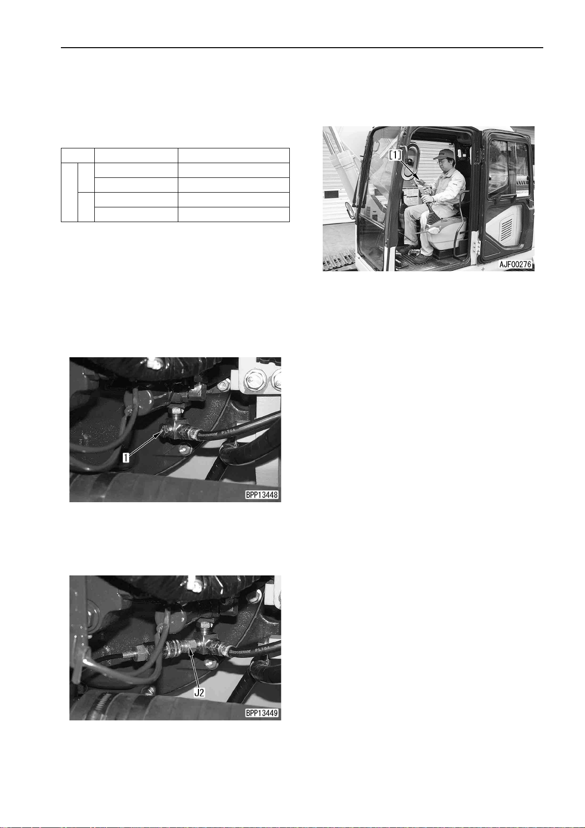
1. Open the pump room cov er and remove control
circuit basic press ure pickup plug (1) under the
hydraulic pump.
790-261-1203 Digital hydraulic tester
799-101-5230 Nipple (10 x 1.25 mm)
2
07002-11423 O-ring
stop the engine. Operate the control levers
several times to release the residual pres sure
in the piping, and then loosen the oil filler cap of
the hydraulic tank slowly to releas e the inte rnal
pressure of the hydraulic tank.
4. Run the engine at hig h idl in g a nd se t a ll the control levers in ne utral and measure the oil pressure.
5. After finishing measurement, remove the measuring instruments and return the removed parts.
a Do not adjust the relief valve for the control cir-
cuit basic pressure is not adjustable.
2. Install nipple J2 and connect it to oil pressure
gauge [1] of hydraulic tester J1.
a Use the oil pressure gauges of 5.9 MPa {60
2
kg/cm
3. Run the engine and heighten the hydraulic oil
temperature to 45 – 55°C.
PC130-7 20-125
}.
(1)

TESTING AND ADJUSTING
TESTING AND ADJUSTING OIL PRESSURE
IN PUMP PC CONTROL CIRCUIT
TESTING AND ADJUSTING
OIL PRESSURE IN PUMP PC
CONTROL CIRCUIT
a Testing and adjusting instruments for oil pressure
in pump PC control circuit
Symbol Part No. Part name
799-101-5002 Hydraulic tester
1
K
MEASURING
Measuring PC valve output pressure (servo piston inlet pressure)
a Before measuring the PC valve outp ut pressure
(servo piston inlet pressure), check that the oil
pressure in the work equipment, swing, and
travel circuits and the basic pressure in the control circuit are normal.
a Measure the PC valve output pressure (servo
piston inlet pressure) and pump discharge pressure simultaneously and compare them.
790-261-1203 Digital hydraulic tester
799-101-5220 Nipple (10 x 1.25 mm)
2
07002-11023 O-ring
• (2): PC va lve ou tput pressure pick up p lug (at
top of hydraulic pump)
3. Install nipple K2 and connect it to oil pressure
gauge [1] of hydraulic tester K1.
a Use th e oi l pr essure gauge of 58.8 MPa {600
2
kg/cm
• The drawing shows the pump discharge
pressure side.
}.
k Lower the work equipment to the ground and
stop the engine. Operate the control levers
several times to rel ease the residual pressure
in the piping, and then loosen the oil filler cap of
the hydraulic tank slowly to release the internal
pressure of the hydraulic tank.
1. Remove the top cover of the control valve and
open the pump room cover.
2. Remove oil pressure pickup plugs (1) and (2).
• (1): Pump discharge pressure pickup plug (at
top of control valve)
• The drawing shows the PC valve output
pressure side.
4. Run the engine and heighten the hydraulic oil
temperature to 45 – 55°C.
20-126 PC130-7
(1)

TESTING AND ADJUSTING
5. While running th e engin e at hig h id ling, measure
the pump discharge press ure and PC valve output pressure (serv o piston inlet pressur e) simultaneously.
• Working mode: A
• Swing lock switch: LOCK (2-stage relief
valve is turned ON and relief pressure is set
high)
• Work equipment, swing, and travel circuits:
Relieve arm circuit by moving arm IN.
a Method of judgment:
If the pump discharge pressure and PC valve
output pressure (servo piston output pressure) are in the following ratio, they are nor-
mal.
Measured oil pressure Ratio of oil pressure
Pump discharge pressure 1
PC valve output pressure
(Servo piston inlet
pressure)
Approx. 3/5
a If the PC valve or the servo piston is abnor-
mal, the PC valve output pressure (servo piston inlet press ure) is "the sa me as the pump
discharge pressure" or "almost 0".
6. After finishing measurement, remove the measuring instruments and return the removed parts.
TESTING AND ADJUSTING OIL PRESSURE
IN PUMP PC CONTROL CIRCUIT
ADJUSTING
Adjusting PC valve
a If either of the following phenomena occurs and
the PC valve seems to be defective, adjust PC
valve (3) according to the procedure shown
below.
• As the working load increases, the engine
speed lowers remarkably.
• The engine speed is normal but the work
equipment speed is low.
a The figure shows the hydraulic pum p seen from
the front side of the machine.
1. Loosen hose fixing (4).
2. Fixing sleeve (5), loosen locknut (6).
3. Turn sleeve (5) to the right or left to adjust the
pump absorption torque.
a If the sleeve is
• turned to th e right, the pump absorption
torque increases.
• turned to the left, the pump absorption
torque decreases.
a Limit the turning angle of the sleeve to the
following range.
• Right turning: Max. 1 turn (360°)
• Left turning: Max. 1/2 turn (180°)
a Change of servo piston stroke per turn of
sleeve: 1.5 mm
4. Fixing sleeve (5), tighten locknut (6).
3 Locknut: 88 – 113 Nm {9 – 11.5 kgm}
PC130-7 20-127
(1)

TESTING AND ADJUSTING
5. Tighten hose fixing nut (4).
6. After finishing adjustment, check that the pressure is normal accordi ng to the above de scrib ed
procedure.
TESTING AND ADJUSTING OIL PRESSURE
IN PUMP PC CONTROL CIRCUIT
20-128 PC130-7
(1)

TESTING AND ADJUSTING
TESTING AND ADJUSTING OIL PRESSURE
IN PUMP LS CONTROL CIRCUIT
TESTING AND ADJUSTING
OIL PRESSURE IN PUMP LS
CONTROL CIRCUIT
a Testing and adjusting instruments for oil pressure
in pump LS control circuit
Symbol Part No. Part name
799-101-5002 Hydraulic tester
1
790-261-1203 Digital hydraulic tester
L
MEASURING
1. Measuring LS valve output pressure (servo
piston inlet pressure)
a Before measuring the LS valve o utput pres-
a Measure the LS valve output pressure (servo
799-101-5220 Nipple (10 x 1.25 mm)
2
07002-11023 O-ring
3 799-400-2701 Differential pressure gauge
sure (servo piston inlet pressure), check that
the oil pressure in the work equipment,
swing, and travel circuits and the ba sic pressure in the control circuit are normal.
piston inlet pressure) and pump discharge
pressure simultaneously and compare them.
• (2): LS valve output pressure pickup
plug (at top of hydraulic pump)
3) Install nipple L2 and connect it to oil pressure
gauge [1] of hydraulic tester L1.
a Use the oil pressure gaug e of 58.8 MPa
{600 kg/cm
• The drawing shows the pump discharge
pressure side.
2
}.
k Lower the work equipment to the ground
and stop the engine. Operate the control
levers several times to release the residual
pressure in the piping, an d then loosen the
oil filler cap of the hydraulic tank slowly to
release the internal pres sure of the hydrau lic tank.
1) Remove the top cover of the control valve
and open the pump room cover.
2) Remove oil pressure pickup plugs (1) and
(2).
• (1): Pump discharge pressure pickup
plug (at top of control valve)
• The drawing show s the LS valve output
pressure side.
PC130-7 20-129
(1)

TESTING AND ADJUSTING
4) Run the engine and heighten the hydraulic
oil temperature to 45 – 55 °C, and then push
up the track shoe on either side with the work
equipment.
TESTING AND ADJUSTING OIL PRESSURE
IN PUMP LS CONTROL CIRCUIT
6) After finishing measurement, remove the
measuring instruments and return the
removed parts.
5) While runni ng the engine at high idli ng, m easure the pump discharge pressure and LS
valve output pressure (servo piston inlet
pressure) simultaneously.
• Working mode: A
• Travel speed switch: Hi
• Work equipment, swing, and travel cir-
cuits:
Set all levers in neutral and run track
shoe on one side idle.
k Checking the safety around the
machine, run the tra ck shoe push ed up
idle.
a Method of judgment:
If the pump discharge pressure and LS
valve output pressur e (servo piston output pressure) are in the following ratio,
they are normal.
Travel lever
Neutral
Full (Idle
running)
Pump
discharge
pressure
MPa {kg/cm
2.9±0.5
{30±5}
7.8±2.0
{80±20}
LS valve
output
pressure
2
}
2.9±0.5
{30±5}
4.4±1.0
{45±10}
Ratio of oil pres-
sure
Almost same
pressure
(1:1)
Almost 3/5
(1:0.6)
2. Measuring LS differential pressure
a Measure the pump discharge pressure and
LS pressure (actuato r load pressure) s imultaneously and calculate the difference
between them.
1) Remove the top cover of the control valve
and remove oil pressure pickup plugs (1) and
(3).
• (1): Pump discharge pressure pickup
plug
• (3): LS pressure pickup plug
20-130 PC130-7
(1)

TESTING AND ADJUSTING
TESTING AND ADJUSTING OIL PRESSURE
IN PUMP LS CONTROL CIRCUIT
2) Install nipple L2 and connect it to the oil
pressure gauge of hydraulic tester L1.
a When using differential pressure gauge:
Connect the pump discharg e pressur e to
the high pressure side (back side) and
connect the LS pressu re to the l ow pres sure side (lower side).
Since the differential pressure gauge
needs a 12-V power source, connect it to
a battery.
a When using oil pressure gauge:
Use the oil pressur e gauge of 58.8 M Pa
{600 kg/cm
2
}.
Since the differential pressure is about
2
2.9 MPa {30 kg/cm
} at maximum, measure it by installing the same gauge to
the pickup plugs alternately.
4) While runni ng the e ngi ne a t hig h id li ng, measure the pump discharge pressure and LS
valve output pressure (servo piston inlet
pressure) simultaneousl y.
• Working mode: A
• Travel speed switch: Hi
• Work equipment, swing, and travel cir-
cuits:
Set all levers in neutral and run track
shoe on one side idle.
k Checking the safety around the
machine, run the tra ck shoe push ed up
idle.
a Calculation of LS differential pressure
(when oil pressure gauge is used):
LS differential pressure = Pump discharge pressure - LS pressu re
a If the LS differential pressure is as fol-
lows, it is normal.
Travel lever
Neutral
Full (Idle running)
LS differential pressure
LS differential pressure
in neutral
(See standard values
table)
Specified LS differential
pressure
(See standard values
table)
3) Run the engine and heighten the hydraulic
oil temperature to 45 – 55°C , and then push
up the track shoe on either side with the work
equipment.
5) After finishing measurement, remove the
measuring instruments and return the
removed parts.
PC130-7 20-131
(1)

TESTING AND ADJUSTING
TESTING AND ADJUSTING OIL PRESSURE
IN PUMP LS CONTROL CIRCUIT
ADJUSTING
Adjusting LS valve
a If the LS differential pressure is abnormal, adjust
LS valve (4) according to the procedure shown
below.
a The figure shows the hydraulic pump s een from
the front side of the machine.
1. Loosen hose sleeve nut (4).
2. Fixing plug (5), loosen locknut (6).
6. After finishing adjustment, check that the pressure is normal a ccording to the abo ve desc ribed
procedure.
3. Turn plug (5) to adjust the differential pressure.
a If the plug is
• turned to the right, the differential pressure rises.
• turned to the left, the differential pressure
lowers.
a Quantity of adjustment (LS differential pres-
sure) per turn of plug:
1,304 kPa {13.3 kg/cm
a Tighten the hose sleeve nut (4) temporarily
and turn the plug, while checking the LS differential pressure.
4. Fixing plug (5), tighten locknut (6).
3 Locknut: 98 – 122.5 Nm {10 – 12.5 kgm}
5. Tighten hose sleeve nut (4).
2
}
20-132 PC130-7
(1)

TESTING AND ADJUSTING
MEASURING SOLENOID VALVE OUTPUT PRESSURE
MEASURING SOLENOID
VALVE OUTPUT PRESSURE
a Measuring instruments for sole noid valve output
pressure
Symbol Part No. Part name
799-101-5002 Hydraulic tester
1
M
a Before measuring the solenoid valve output
pressure, check that the basic pressure in the
control circuit is normal.
k Lower the work equipment to the ground and
1. Remove the underco ver of the control valve and
disconnect outlet hoses (1) – (4) of the soleno id
valves to be measured.
790-261-1203 Digital hydraulic tester
2 799-401-3100 Adapter (Size 02)
stop the engine. Operate the control levers
several times to release the residual pres sure
in the piping, and then loosen the oil filler cap of
the hydraulic tank slowly to releas e the inte rnal
pressure of the hydraulic tank.
a Use the oil pressure gauges of 5.9 MPa {60
2
kg/cm
}.
a The figure shows the measuring instruments
connected to the outlet hose of the 2-stage
relief solenoid valve.
4. Run the engine and heighten the hydraulic oil
temperature to 45 – 55°C.
No. Solenoid valve to be measured
1 2-stage relief solenoid valve
2 Swing holding brake solenoid valve
3 Travel speed solenoid valve
4 PPC pressure lock solenoid valve
a Since outlet hose (4) of the PPC pressure
lock solenoid valve has a quick coupler,
measure the output pressure on the PPC
valve side.
2. Install adapter M2 and con nec t th e di sc on nected
hose again.
5. Run the engine at high idling, operate the control
levers and switches to turn the solenoid valve
ON or OFF, and measure the oil pressure.
a For the conditions for turning the solenoid
valve ON and OFF, see the operations table
of each solenoid valve.
a The operating condition of the solenoid valve
can be also check ed with the monitorin g
function [02] of the monitor panel (excluding
the PPC pressure lock solenoid valve).
a If the output pressure is as follows, the sole-
noid valve is normal.
Solenoid v alve Output pressure
OFF
(Deenergized)
ON (Energized)
0 MPa {0kg/cm
Almost same as contro l basi c
pressure
(See standard values table)
2
}
3. Install nipple [1] of hydraulic tester M1 and connect it to hydraulic gauge [2].
PC130-7 20-133
(1)

TESTING AND ADJUSTING
6. After finishing measurement, remove the measuring instruments and return the removed parts.
Operation table of 2-stage relief solenoid valve
MEASURING SOLENOID VALVE OUTPUT PRESSURE
Operating condition
One-touch power maximizing switch: ON (8.5-sec timer)
Swing lock switch
Other than above condition OFF
Operation
ONTr avel signal
Operation table of swing holding brake solenoid valve
Operating condition
Work equipment, swing, and travel signals Any one is turned ON
Swing holding brake release switch: RELEASE (Upper) position
Other than above condition OFF
Operation
ON
Operation table of travel speed brake solenoid valve
Operating condition Operation
Travel speed switch: Lo
Auto shift function operates during run at Hi
Overheat prevention function operates during run
at Hi
Engine speed: Below 1,500 rpm
Pump pressure: Above 30.4 MPa {310 kg/cm
Hydraulic oil temperature: Above 95°C
2
}
OFF
Other than above condition ON
Operation table of PPC pressure lock solenoid valve
Operation
Safety lock lever
Operating condition
LOCK position OFF
FREE position ON
20-134 PC130-7
(1)

TESTING AND ADJUSTING
MEASURING PPC VALVE
OUTPUT PRESSURE
a Measuring instruments for PPC valve output
pressure
Symbol Part No. Part name
N
a Before measuring the PPC valve output pres-
sure, check that the basic press ur e in the co ntro l
circuit is normal.
799-101-5002 Hydraulic tester
790-261-1203 Digital hydraulic tester
MEASURING PPC VALVE OUTPUT PRESSURE
k Lower the work equipment to the ground and
stop the engine. Operate the control levers
several times to release the residual pres sure
in the piping, and then loosen the oil filler cap of
the hydraulic tank slowly to releas e the inte rnal
pressure of the hydraulic tank.
1. Disconnect PPC oi l pressure switches (1) – (4)
of the circuit to be measured.
No. Circuit to be measuredNo.Circuit to be measured
1 Boom RAISE (S06) 7 Swing RIGHT (S07)
2 Boom LOWER (S02) 8 Swing LEFT (S03)
3 Arm IN (S04) 9 Travel (S30)
4 Arm OUT (S04) 10
5 Bucket CURL (S08) 1 1
6 Bucket DUMP (S01)
1ATT on front side
(S10)
1ATT on rear side
(S11)
a Since PPC oil pressure switches (1) – (8) are
installed in the battery room, open the battery room cover.
a Since PPC oil pressure switches (10) and
(11) are installed in the battery room, open
the battery room cover.
2. Install nipple [1] of hydraulic tester N and connect it to oil pressure gauge [2].
a Use the oil pressure gauges of 5.9 MPa {60
2
kg/cm
}.
a The figure shows the measuring instruments
installed to the mounting part of the swing
LEFT PPC pressure switch.
a Since PPC oil pressure s wi tch (9) is installed
on the under side of the floor frame, remove
the cab undercover (on the front side).
3. Run the engine and heighten the hydraulic oil
temperature to 45 – 55°C.
PC130-7 20-135
(1)

TESTING AND ADJUSTING
4. Run the engine at high idling and measure the oil
pressure while the con trol lever or pedal of the
measured circuit is in neutral and while it is operated to the stroke end.
a If the PPC valve output pressure is as fol-
lows, the solenoid valve is normal.
ADJUSTING PLAY OF WORK EQUIPMENT AND SWING PPC VALVES
MEASURING SOLENOID VALVE OUTPUT PRESSURE,
ADJUSTING PLAY OF WORK
EQUIPMENT AND SWING PPC
VALVES
a If the work equipment and swing levers have
large play, adjust them according to the following
procedure.
1. Remove the work equipment and swing PPC
valve assembly.
2. Remove bellows (1).
3. Loosen locknut (2) and tighten disc (3) until it
touches the heads of 4 pistons (4).
a Do not move the piston at this time.
4. Fix disc (3) and t ighten locknut (2) to the specified torque.
3 Locknut: 69 – 88 Nm {7 – 9 kgm}
Lever/Pedal Output pressure
In neutral
Operated to
stroke end
5. After finishing measurement, remove the measuring instruments and return the removed parts.
Almost same as control basic
pressure (See standard values
table)
0 MPa {0kg/cm
2
}
5. Install bellows (1).
6. Install the work equipment and swing PPC val ve
assembly.
20-136 PC130-7
(1)

TESTING AND ADJUSTING
TESTING PARTS WHICH
CAUSE HYDRAULIC DRIFT OF
WORK EQUIPMENT
a If the work equipment (cylinder) drifts hydrauli-
cally, check to see if the ca use i s on th e cylinde r
packing side or con trol valv e side or hydrau lic
drift prevention valv e side (if equip ped) acco rding to the following procedure.
1. Testing boom cylinder and bucket cylinder
1) Set the ma chine in the posi tion of mea suring
hydraulic drift and stop the engine.
a Fill the bucket with a rated load or with
dirt and sand.
TESTING PARTS WHICH CAUSE HYDRAULIC DRIFT OF
WORK EQUIPMENT
2) Operate the arm control lever in the IN position.
• If the lowe ring speed is increased at this
time, the cylinder packing is defective.
• If the lowering s peed doe s not ch ange at
this time, the control valve is defective.
a Operate the control lever wh ile the start-
ing switch is in the ON position.
a If the pressure in the accu mulato r is l ost,
run the engine for about 1 0 seconds to
heighten the pressure in the accumulator.
2) When testing the boom cylinder, set the
boom control lever in the RAISE position.
When testing the bucket cylinder, set the
bucket control lever in the CURL position.
• If the lower ing speed is increased at this
time, the cylinder packing is defective.
• If the lowering speed do es not c hange at
this time, the co ntrol valve or hydrau lic
drift prevention valve (if equipped) is
defective.
a Operate the control lever while the start-
ing switch is in the ON position.
a If the pressure in the accumulator is lost,
run the engine for about 10 seconds to
heighten the pressure in the accumulator.
2. Testing arm cylinder
1) Stop the arm cylinder ab out 100 mm before
the IN stroke end and stop the engine.
[Reference]
Reason why the lo wering speed is increased b y
the above operation when the cylinder packing is
the cause of the hydraulic drift:
1) If the machine is set in the above position (where
the holding pressure is applied to the bottom
side), the oil leaks from the bottom side to the
head side. Since the volum e on the head si de is
less than that on the bottom side by the volume
of the rod, the pressure in the head side is
increased by the oil flowing in from the bottom
side.
2) As the p ressure in the h ead side is inc reased, it
is balanced at a c ertain leve l (whic h depends on
the leakage), and then the lowering speed is lowered.
3) If the circuit on the head side is opened to the
drain circuit by the above operation of the le ver
(the bottom side is clos ed by the check valve at
this time), the oil o n the head side flows in the
drain circuit. As a result , the pressure is unbalanced and the lowering speed is increased.
PC130-7 20-137
(1)

TESTING AND ADJUSTING
3. Testing PPC valve
While the pressure in the accumulator is high,
set the safety lock lever in the LOCK/FREE position and measure the lowering distance.
a Operate the control lever while the starting
switch is in th e ON position.
a If the pressure in the accumulator is l ost, run
the engine for about 10 seconds to heighten
the pressure in the accumulator.
a If there is a difference in the lowering dis-
tance between the LOCK pos iti on and FR EE
position, the PPC valve is defective (it has an
internal defect).
TESTING PARTS WHICH CAUSE HYDRAULIC DRIFT OF
WORK EQUIPMENT
20-138 PC130-7
(1)

TESTING AND ADJUSTING
MEASURING OIL LEAKAGE
MEASURING OIL LEAKAGE
a Measuring instruments fro oil leakage
Symbol Part No. Part name
P
1. Measuring oil leakage from boom cylinder
1) Run the e ngine and heighten the eng ine oil
2) Disconnect hose (1) on the cylinder head
Commercially
available
temperature to 45 – 55°C, and then move
the boom cylinder to the RAISE stroke end.
k Release the residual pressure in the
piping on the boom cylinder hea d side.
For details, see RELEASING RESIDUAL PRESSURE IN HYDRAULIC CIRCUIT (Operate the lever in the boom
RAISE direction only, however).
side and block the hose side with a plate.
k Take care not to disconnect the hose on
the cylinder bottom side.
a Use the following part to block the hose
side.
07376-50422 (Plug No. 04)
Measuring cylinder
2. Measuring oil leakage from arm cylinder
1) Run the engine an d raise the engi ne oil tem-
perature to 45 – 55°C, and then move the
arm cylinder to the IN stroke end.
k Release the residual pressure in the
piping on the arm cylinder head side.
For details, see RELEASING RESIDUAL PRESSURE IN HYDRAULIC CIRCUIT (Operate the lever in the arm IN
direction only, however).
2) Disconnect hose (2) on the cylinder head
side and block the hose side with a plate.
k Take care not to disconnect the hose on
the cylinder bottom side.
a Use the following part to block the hose
side.
07376-50522 (Plug No. 05)
3) Run the en gine at high idling an d relieve the
boom circuit by raising the boom.
k Take care not to "lower the boom".
4) Measure the oil leakage for 1 minute after 30
seconds since relieving is started.
5) After finishing measurement, return the
removed parts.
3) Run the engine at high idling and rel ieve the
arm circuit by moving the arm IN.
k Take care not to "move the arm OUT".
4) Measure the oil leakage for 1 minute after 30
seconds since relieving is started.
5) After finishing measurement, return the
removed parts.
PC130-7 20-139
(1)

TESTING AND ADJUSTING
MEASURING OIL LEAKAGE
3. Measuring oil leakage from bucket cylinder
1) Run the engine an d raise the engi ne oil temperature to 45 – 55°C, and then move the
bucket cylinder to the CURL strok e end and
stop the engine.
k Release the residual pressure in the
piping on the bucket cylinder head side.
For details, see RELEASING RESIDUAL PRESSURE IN HYDRAULIC CIRCUIT (Operate the lever in the arm
CURL direction only, however).
2) Disconnect hose (3) on the cylinder head
side and block the hose side with a plate.
k Take care not to disconnect the hose on
the cylinder bottom side.
a Use the following part to block the hose
side.
07376-50422 (Plug No. 04)
4. Measuring oil leakage from swing motor
1) Run the engin e and rais e the en gine oi l temperature to 45 – 55°C.
2) Disconnect drain hose (4) and block the
hose side with a plug.
a Use the following part to block the hose
side.
07376-50522 (Plug No. 05)
3) Turn the swi ng loc k switc h ON.
4) Run the engi ne at high idling and rel ieve the
swing circuit by swinging.
a Measure the oil leakage for 1 minute
after 30 seconds since relieving is
started.
a After measuring 1 time, swing 180°, and
then measure again.
5) After finishing measurement, return the
removed parts.
3) Run the engine at hig h idling and relieve the
bucket circuit by curling the bucket.
k Take care not to "dump the bucket".
4) Measure the oil leakage for 1 minute after 30
seconds since relieving is started.
5) After finishing measurement, return the
removed parts.
20-140 PC130-7
(1)

TESTING AND ADJUSTING
5. Measuring oil leakage from travel motor
1) Run the engi ne and r aise the engine oil tem perature to 45 – 55°C, and th en remove the
travel motor cover.
2) Run the engine and lock the travel system.
k Put pin [1] between the sprocket and
track frame to lock the travel system
securely.
MEASURING OIL LEAKAGE
3) Disconnect drain hose (5) of the travel motor
and block the hose side with a plug.
a Use the following part to block the hose
side.
07376-50422 (Plug No. 04)
4) Run the engine at high idling, relieve the
travel circuit, and measure the oil leakage.
k Wrong operation of the lev er can c ause
an accident. Accordingly, make signs
and checks securely.
a Measure the oil leakage for 1 minute
after 30 seconds since relieving is
started.
a Measure several times, moving the
motor a little (changing the position of the
valve plate and cylinder and that of the
cylinder and piston) each time.
5) After finishing measurement, return the
removed parts.
PC130-7 20-141
(1)

TESTING AND ADJUSTING
RELEASING RESIDUAL PRESSURE IN HYDRAULIC CIRCUIT
RELEASING RESIDUAL
PRESSURE IN HYDRAULIC
CIRCUIT
1. Releasing residual pressure in hydraulic tank
k Since the hydraulic tank is enclosed and
pressurized, release the residual pressure
in it when removin g a hose or a plug connected to it.
1) Lower the work equi pm ent to the grou nd i n a
stable position and stop the engine.
2) Loosen oil f iller cap (1) of t he hydraulic tank
gradually to release the air in the tank.
a If you open the pump room cover, you
can loosen the o il fill er cap f rom th e right
side of the machine.
4) Repeat steps 2) and 3) above 2 – 3 times,
and the residual pressure in the piping is
released completely.
3. Releasing residual pressure in swing motor
circuit
a The residual pressure i n the s win g motor cir-
cuit can be released by performing the operation for RELEASING RESIDUAL
PRESSURE IN HYDRAULIC CYLINDER
CIRCUIT (Operate the lever in the swing
direction only, however).
4. Releasing residual pressure in travel motor
circuit
a Since the control valve spool of the travel
motor circuit is open, the pr essure in this circuit can be rele as ed by performing RE LEAS ING RESIDUAL PRESSURE IN
HYDRAULIC TANK.
2. Releasing residual pres sure in hydraulic cylinder circuit
k When disconnecting a pipe between a
hydraulic cylinder and the control valve,
release the residual pressure in the piping
according to the following procedure.
1) Release the resid ual pressure in the hydrau-
lic tank. For details, see RELEASING
RESIDUAL PRESSURE IN HYDRAULIC
TANK.
a Keep the oil filler cap of the hydraulic
tank removed.
2) Turn the starting switch ON and set the
safety lock lever in the FREE position, and
then operate the work equipment control
levers on both sides forward, backward, to
the right, and to the left.
a The control valve is operated by the
pressure in the accumulator. The pressure in the accumulator is used up, however, after the control valve is ope ra ted 2
– 3 times.
3) Run the engine at low idling for 10 seconds
to heighten the pressure in the accumulator.
20-142 PC130-7
(1)

TESTING AND ADJUSTING
BLEEDING AIR FROM EACH PART
Air bleeding item 1 2 3 4 5 6
BLEEDING AIR FROM EACH PART
Air bleeding procedure
Contents of work
• Replacing hydraulic oil
• Cleaning strainer
• Replacing return filter element
• Replacing and repairing hydraulic
pump
• Removing suction piping
• Replacing and repairing control v alve
• Removing control valv e piping
• Replacing and repairi ng cylinder
• Removing cylinder piping
• Replacing and repairing swing moto r
• Removing swing motor piping
• Replacing and repairing travel motor
• Removing travel motor piping
• Replacing and repairing swivel joint
• Removing swivel joint piping
Bleeding air
from
hydraulic
pump
Starting
engine
Bleeding air
from cylinder
qqq
qq
qqq q
qq q
qq q
qqq
qqq
qq
Bleeding air
from swing
motor
Bleeding air
from travel
motor
q
(See note)q (See note)
Note: Bleed air from the swing motor and travel motor only when the oil in the motor cases is drained.
1. Bleeding air from hydraulic pump
1) Open the pu mp room cover, loosen bleeder
(1), and check that oil flows out.
2) If the oil does not flow out, dis connect drain
hose (2) and fill the pump case with oil
through the drain port.
a Fix the drain hose adapter to a place
higher than the oil level in the hydraulic
tank.
a Fill the pump case with oil until oil con-
taining no bubbles flows out of the
bleeder.
3) After oil containing no bubbles flows out of
bleeder (1), tighten the bleeder.
3 Air bleeder:
7.8 – 9.8 Nm {0.8 – 1.0 kgm}
a If the drain hose has been disconn ected,
connect it after tightening the bleeder.
2. Starting engine
When running the engine after performing step
1, keep its speed at low idling for 10 minutes.
a If the engine coolant temperature is low and
the automatic warm-up operat ion is started,
stop the engine tem porarily and res et the
automatic warm-up operation with the fuel
control dial (Set the starting swit ch in the ON
position and ho ld the fue l control di al in the
MAX position for 3 seconds, and the automatic warm-up operation is reset).
Checking oil
level and
starting
operation
q
PC130-7 20-143
(1)

TESTING AND ADJUSTING
BLEEDING AIR FROM EACH PART
3. Bleeding air from cylinder
a If a cylinder was replaced, bleed air from it
before connecting the work equipment. In
particular, the boom cylinder does not move
to the lowering stroke end, if it is installed to
the work equipment.
1) Run the engine at lo w idling for ab out 5 minutes.
2) Running the engine at low idling, raise and
lower the boom 4 – 5 times.
a Stop the piston r od abo ut 100 mm befor e
each stroke end. Do not relieve the oil.
3) Running the engine at high idling, perform
step 2).
4) Running the engine at low idling, move the
piston rod to the s troke end and relieve t he
oil.
5) Bleed air from the arm cylinder and bucket
cylinder according to steps 2) – 4).
4. Bleeding air from swing motor
1) Run the engine at low idling.
2) Loosen air bleeding plug (3) and check th at
the oil oozes out, and then tighten the air
bleeding plug.
3 Air bleeding plug:
25.5 – 34.3 Nm {2.5 – 3.5 kgm}
3) If the oil does not oozes out, remove air
bleeding plug (3) and fill the pump case with
oil.
5. Bleeding air from travel motor
1) Remove the travel motor cover and run the
engine at low idling.
2) Loosen drain hose (4) and check that oil
oozes out, and then tighten the drain hose.
3) Running the engine at low idling and using
the work equipment, raise the tr ack shoe on
either side.
4) Running the engine at low idling, run the
raised track shoe idle slowly for about 2 minutes.
a Run the track shoe forward and in
reverse as evenly as possible.
a Run the track shoe on the opposite side
idle similarly.
4) Run the engine at low idling and swing slowly
2 turns or more in each direction.
20-144 PC130-7
(1)

TESTING AND ADJUSTING
6. Checking oil level and starting work
1) Run the en gine, retract the arm cylinde r and
bucket cylinder to the stroke ends , lower the
work equipment to the gro und, and stop the
engine.
2) Check the oil level by sight gauge (5) on the
side of the hydraulic tank.
a If the oil level is between lines H and L, it
is normal.
a If the oil level is below line L, add new oil.
BLEEDING AIR FROM EACH PART
PC130-7 20-145
(1)

TESTING AND ADJUSTING
TESTING PROCEDURE FOR
DIODE
a Test an assembled-type diode (18-pin) or a diode
(2-pin) according to the following procedure.
a The conductive direction of an assembled-type
diode is shown in the following figure.
a The conductive direction of a diode is marked on
its surface.
TESTING PROCEDURE FOR DIODE
2. When using an analog circuit tester
1) Set the circuit tester in the resistance range.
2) Apply the test pins as shown below and
check movement of the pointer.
i) Apply the red (+) test pin to the anode (P)
side of the diode and the black (-) test pin
to the cathode (N) side.
ii) Apply the red ( +) test pin to th e cathode
(N) side of the diode and the black (-) test
pin to the anode (P) side.
3) Judge t he condition of the diode from movement of the pointer.
• The pointer does not move in i) above
but moves in ii): Nor mal (Moving angl e
(Resistance) depends on the type and
measurement range of the circuit tester,
however)
• The pointer moves in both i) and ii):
Defective (Internal short circuit)
• The pointe r does not move in either of i)
and ii): Defective (Internal disconnection)
1. When using a digital circuit tester
1) Set the circ uit tester in the diode r ange and
check the indicated value.
a If an ordinary tester is used, the voltage
of the battery in itself is indicated.
2) Apply the red (+) test pin to the anode (P)
side of the diode and the black (-) test pin to
the cathode (N) side and read the indicated
value.
3) Judge the condition of the diode from the
indicated value.
• The indicated value does not change:
There is not continuity (Defective).
• The indicated value changes: There is
continuity (Normal) (Note).
Note) In the case of a silicon diode, t he cir-
cuit tester indicates a value of 460 –
600.
20-146 PC130-7
(1)

TESTING AND ADJUSTING
SPECIAL FUNCTIONS OF MONITOR PANEL
SPECIAL FUNCTIONS OF MONITOR PANEL
Section to display special functions
1. Display section
2. Service meter section
PC130-7 20-147
Section to operate special function 1
(Basic operation)
3. Caution buzzer stop switch
4. Auto-decelerator switch
5. Setting switch (Black switch)
6. Travel speed shifting switch
Section to operate special function 2
(Selecting operation and special
operation)
7. Working mode selector switch (UP)
8. Working mode selector switch
(DOWN)
9. Swing lock switch
(1)

TESTING AND ADJUSTING
SPECIAL FUNCTIONS OF MONITOR PANEL
Ordinary functions and special functions of monitor panel
The monitor panel has the ordinary functions and special functions and displays various pieces of information
on display section (1) and service meter section (2).
Some items are displayed automatically according to the internal setting of the monitor panel and the others are
displayed by operating switches.
1. Ordinary functions: Operator menu
The items in this menu are displayed normally or displayed automatically when a trouble occurs.
2. Special functions: Service menu
The items in this menu are not displayed normally. Each serviceman can display them by operating special
switches. These functions are used for special setting, testing, adjusting, or troubleshooting.
Flow of each function
Ordinary functions (Operator menu)
1 Function of displaying service meter 3 Function of displaying error code [01]
O <Automatic>
2 Function of displaying user code 5 Function of adjusting governor [03]
4 Monitoring function [02]
6 Function of selecting maintenance period [04]
7 Function of selecting default working mode [05]
8 Function of adjusting service meter
<Operation of switch> O
9 Special function of monitoring replacement of engine oil
Special functions (Service menu )
a Each number in [ ] is a code No. displayed in the service meter section when the menu is selected.
20-148 PC130-7
(1)

TESTING AND ADJUSTING
SPECIAL FUNCTIONS OF MONITOR PANEL
Display of operator menu
a Only outline of the operator menu is descr ibed in
this section. For details of each menu, see
OPERATION MANUAL or the volume of
STRUCTURE AND OPERATION.
1. Function of displaying service meter
While the machine is used norm ally, the monitor
panel displays the following information.
• Display section (1): Nothing is displayed
• Service meter section (2): Service meter
2. Function of displaying user code
If the machine has any trouble, the corre sponding user code is displayed automatically in display section (1) an d the caution bu zzer i s turned
ON to urge the operator to take a proper remedy,
depending on the degree of the trouble.
a Service meter section (2) continues display-
ing the service meter.
a For displayed user codes and the remedies
shown to the operator, see "User codes and
remedies shown to operator".
a Each user code simply shows occurrence of
a trouble to the operator. To find out the
cause of the trouble, a serviceman must
check the error code with the "Function of
displaying error code [01]" in the se rvice
menu.
<Reference>
A user code is displayed only when a serious trouble
occurs.
Even if a user code is not dis played, a troubl e may
have occurred. If you feel any abnormality, be sure
to check for an error code with the "Function of displaying error code [01]" in the service menu.
PC130-7 20-149
(1)

TESTING AND ADJUSTING
a User codes and remedies shown to operator
SPECIAL FUNCTIONS OF MONITOR PANEL
User
code
E02 Error in pump control system
E03 Error in swing brake system
E05 Error in governor system Have the machine inspected immediately.
Error mode Remedy (shown to operator)
If the emergency pump drive switch is set in the upper position, the machine can operate normally. Have the machine
inspected immediately, however.
Set the swing holding brake release switch in the upper position to release the brake. Apply the swing brake manually
with the swing lock swit ch, if necessary. The brake may not
be released, depending on the cause of the failure. In any
case, have the machine inspected immediately.
Caution
buzzer
q
q
q
20-150 PC130-7
(1)

TESTING AND ADJUSTING
SPECIAL FUNCTIONS OF MONITOR PANEL
Operation and display of service menu
How to select service menu
a When using the general functions in the service
menu, perform the following switch operation to
change the screen of the monitor panel.
3. Function of displaying error code [01]
4. Monitoring function [02]
5. Function of adjusting governor [03]
6. Function of selecting maintenance period
[04]
7. Function of selecting default working
mode [05]
1) Operating switches
Holding caution buzzer stop switch (3), hold auto
decelerator switch (4) for 2.5 seconds.
3) Selecting menu
Holding caution bu zzer stop switch (3), operate
working mode selector switches (7) and (8) to
select a menu you will use.
• UP switch (7): Menu No. increases.
• DOWN switch (8): Menu No. decreases.
Menu
No.
01 Function of displaying error code
02 Monitoring function
03 Function of adjusting governor
04
05
Function of selecting maintenance
period
Function of selecting default working
mode
Service menu
(Excluding special functions)
4) Executing menu
Select a menu you will u se and press set sw itch
(5), and the menu is executed.
2) Displaying display section and service meter
section
If the switches are operated as shown above, the
first menu No. [01] (Monitoring function) is displayed in service meter section (2).
a Nothing is displayed in display s ection (1).
5) Finishing service menu
Holding caution buzzer stop switch (3), hold auto
decelerator switch (4) for 2.5 seconds (similarly
to the selecting operation).
a The service menu is finished and the ordi-
nary screen appears.
a The service menu can be also finished by
turning the starting switch OFF while the service menu is selected. (In this case, the ordinary screen appears when the starting
switch is turned ON again.)
a To use the special functions in the ser v ice men u ,
you must operate the swi tches differently from
the above. See details of each menu.
8. Function of adjusting service meter
9. Special function of monitoring replace-
ment of engine oil
PC130-7 20-151
(1)

TESTING AND ADJUSTING
3. Function of displaying error code [01]
With this function, you can check t he error code
of a trouble which is occurring at pr esent or has
occurred in the past.
1) Selecting and executing function
i) Sel ect menu No . [01] in the menu sele c-
tion mode.
ii) Press set switch (5) to ex ecute this func-
tion.
SPECIAL FUNCTIONS OF MONITOR PANEL
3) Informa tion displayed in display section an d
service meter sec tion 2 (When error code is
not recorded)
If an error code is not recorded, display section (1) and servic e meter s ecti on (2) display
as shown below.
2) Information displayed in display section and
service meter se ction 1 (When er ror code is
recorded)
If an error code is recorded, the following
information is displayed in display section (1)
and service m eter section (2 ).
(a): Error code
(b): Service meter reading increased after
trouble occurred
(c): Mark [E] to indicate that troubl e is occur-
ring at present
a Mark [E] to indicate that a trouble is
occurring at present in dicates that the
error code is being detected now. It is
not displayed if the trouble has been
repaired or the error code is not
detected.
a For the error codes which the monitor
panel and governor and pump controller
can detect, see the "Error codes table".
4) Numbe r of recorded er ror codes and display
order of them
This function can record up to 20 error
codes, which are displayed in order from the
latest one.
a If a new trouble occurs while 20 error
codes are recorded, the ol dest error
code is deleted and the error code of the
new trouble is recorded.
20-152 PC130-7
(1)

TESTING AND ADJUSTING
5) Change of displayed error codes
Holding caution bu zzer s top swi tc h (3) , op er ate working mode selector switches (7) and
(8) to change the displayed error codes.
• UP switch (7): Next error cod e appea r s.
• DOWN switch (8): Previous error code
appears.
6) How to delete error code
i) Holding caution buzzer stop switch (3),
turn the starting switch OFF and keep
holding caution buzzer stop switch (3).
ii) Under the above condition, turn the start-
ing switch ON again and hold caution
buzzer stop switch (3) for 5 seconds.
a An error code having the mark [E] cannot
be deleted.
SPECIAL FUNCTIONS OF MONITOR PANEL
PC130-7 20-153
(1)

TESTING AND ADJUSTING
SPECIAL FUNCTIONS OF MONITOR PANEL
Error codes table
User code Error code Trouble
— 104 Clogging of air cleaner
— 108 Overheating of engine coolant
— 112 Short circuit in wiper motor drive forward system
— 113 Short circuit in wiper motor drive reverse system
— 114 Short circuit in windshield washer drive system
— 115 Trouble in operati on of wi nds hi eld wiper
— 116 Trouble in storage of windshield wiper
E03 203 Short circuit in swing holding brake solenoid
— 205 Short circuit in 2-stage relief solenoid
— 206 Short circuit travel speed shifting solenoid
E03 213 Disconnection in swing holding brake solenoid
— 215 Disconnection in 2-stage relief solenoid
— 216 Disconnection travel speed shifting solenoid
— 217 Abnormality in input model code
— 218 Disconnection in S-NET signal line
— 222 Short circuit in LS-EPC solenoid
— 223 Disconnection in LS-EPC solenoid
— 224 Abnormality in pump pressure sensor
— 226 Abnormality in pressure sensor power supply
— 227 Abnormality in engine speed sensor
E02 232 Short circuit in PC-EPC solenoid
E02 233 Disconnection in PC-EPC solenoid
— 251 Abnormality in overload pressure sensor
— 301 Engine low idling speed out of standard range
— 302 Engine high idling speed out of standard range
— 306 Abnormality in governor potentiometer
E05 308 Abnormality in fuel control dial
— 315 Short circuit in battery relay output line
— 316 Step-out of governor motor
E05 317 Disconnection in phases A and B of governor motor
E05 318 Short circuit in phases A and B of governor motor
20-154 PC130-7
(1)

TESTING AND ADJUSTING
4. Monitoring function [02]
With this function, you can monitor the revolution
speed, oil pressure, current, voltage, input condition, output condit ion , etc. in r eal time by the signals from the sensors, switches, and solenoids
installed to various parts of the machine.
1) Selecting and executing function
i) Selec t menu No. [02] in the menu selec -
tion mode.
ii) Press set switch (5) to exec ute this func-
tion.
SPECIAL FUNCTIONS OF MONITOR PANEL
3) Information di splayed in display section and
service meter section 1 (When numeral code
is displayed)
If a numeral monitoring code is sel ected, the
following information is displayed in display
section (1) a nd service meter section (2).
(a): Monitoring code
(b): Monitoring information (Value is dis-
played)
2) Selecting and executing monitoring code
Holding caution bu zzer s top swi tc h (3) , op er ate working mode selector switches (7) and
(8) to select a mo nitoring code displayed in
service meter section (1).
• UP switch (7): Code No. increases.
• DOWN switch (8): Code No. decreases.
a This function displays monitoring code
[001] and its information first.
a For the items and code Nos. which you
can monitor, see the "Monitoring codes
table".
PC130-7 20-155
(1)

TESTING AND ADJUSTING
4) Information displayed in display section and
service meter se ction 2 (When 6-bit code is
displayed)
If a 6-bit monitor ing cod e is selec ted, th e f ollowing information is displayed in display
section (1) and service mete r secti on (2 ).
(a): Monitoring code
(b): Monitor ing information (6 pieces of info r-
mation are displayed in bits)
a In the 6-bit display mode, only the top
and bottom of the 7-segment mark are
used to display. "Solid black" indicates
the ON state, and "white on black background" indicates the OFF state.
a For the No. of each bit, see the "Monitor-
ing codes table" and the drawing
attached to it.
SPECIAL FUNCTIONS OF MONITOR PANEL
20-156 PC130-7
(1)

TESTING AND ADJUSTING
SPECIAL FUNCTIONS OF MONITOR PANEL
Monitoring codes table
Code Monitoring item Unit Remarks
001 Monitor panel model code Numeral
002 Governor and pump controll er model code (Pump side) Numeral
003 Governor and pump controller model code (Engine throttle side) Numeral
008 Connecting condition of network Numeral
010 Engine speed 10rpm
011 Pump discharge pressure
012 Pump discharge pressure
013 PC-EPC solenoid output current 10mA
015 LS-EPC solenoid output current 10mA
016 2nd throttle speed 10rpm
018 (Unused) —
019 (Unused) —
a Swing oil pressure switch (ON) (6bit)
kg/cm
kg/cm
2
2
020 Input condition of switch 1
021 Input condition of switch 2
022 Input condition of switch 3
b Travel oil pressure switch (ON) (6bit)
c Boom LOWER oil pressure switch (ON) (6bit)
d Boom RAISE oil pressure switch (ON) (6bit)
e Arm IN oil pressure switch (ON) (6bit)
f Arm OUT oil pressure switch (ON) (6bit)
a Bucket CURL oil pressure switch (ON) (6bit)
b Bucket DUMP oil pressure switch (ON) (6bit)
c (Unused) (6bit)
d Service oil pressure switch (ON) (6bit)
e (Unused) (6bit)
f (Unused) (6bit)
a (Unused) (6bit)
b (Unused) (6bit)
c One-touch power maximizing switch (ON) (6bit)
d Swing holding brake release switch (RELEASE) (6bit)
e Swing lock switch (LOCK) (6bit)
f (Unused) (6bit)
a (Unused) (6bit)
b (Unused) (6bit)
023
Drive condition of solenoid valve
c Swing hol ding brake solenoid (O N) (6bit)
d (Unused) (6bit)
e 2nd relief solenoid (ON) (6bit)
f Travel speed shifting solenoid (ON) (6bit)
PC130-7 20-157
(1)

TESTING AND ADJUSTING
Code Monitoring item Unit Remarks
024 (Unused) —
a Model sele ction 1 (Connected to ground) (6bit)
b Model sele ction 2 (Connected to ground) (6bit)
SPECIAL FUNCTIONS OF MONITOR PANEL
027
030 Fuel control dial input voltage 10mV
031 Governor pote nti om ete r input voltage 10mV
032 Controller power source voltage 100mV
033 Governor motor phase A output current 10mA
034 Governor motor phase B output current
035 Battery relay BR output voltage 100mV
036 Input condition of signal
Input condition of model
selection signal
c Model selection 3 (Connected to ground) (6bit)
d Model sele ction 4 (Connected to ground) (6bit)
e Model sele ction 5 (Connected to ground) (6bit)
f (Unused) (6bit)
10mA
a (Unused) (6bit)
b (Unused) (6bit)
c (Unused) (6bit)
d (Unused) (6bit)
e Starting switch signal C (START) (6bit)
f (Unused) (6bit)
a Battery relay (DRIVEN) (6bit)
b (Unused) (6bit)
037 Output condition of signal
041 Engine coolant sensor input voltage 10mV
042 Fuel level sensor input voltage 10mV
043 Alternator input voltage 10mV
044 (Unused) —
045 Input con dit ion 4 of switch
c (Unused) (6bit)
d (Unused) (6bit)
e (Unused) (6bit)
f (Unused) (6bit)
a Starting switch signal ACC (ON) (6bit)
b Starting switch signal C (START) (6bit)
c Starting switch signal R1 (HEAT) (6bit)
d Lamp switch (ON) (6bit)
e (Unused) (6bit)
f (Unused) (6bit)
20-158 PC130-7
(1)

TESTING AND ADJUSTING
Code Monitoring item Unit Remarks
a Air cleaner clogging switch (OPEN) (6bit)
b (Unused) (6bit)
c Engine oil pressure switch (OPEN) (6bit)
046 Input condition of sensor
d Engine oil level switch (OPEN) (6bit)
e (Unused) (6bit)
f Alternator (Normal generation) (6bit)
a Swing lock switch (LOCK) (6bit)
b Caution buzzer stop switch (ON) (6bit)
c Windows limit switch (ON) (6bit)
049 Input condition 5 of switch
d Wiper contact W (ON) (6bit)
e Wiper contact P (ON) (6bit)
f (Unused) (6bit)
200 Monitor panel program version Numeral
SPECIAL FUNCTIONS OF MONITOR PANEL
201 Governor and pump controller program version Numeral
Display of numeral code Display of 6bit
PC130-7 20-159
(1)

TESTING AND ADJUSTING
SPECIAL FUNCTIONS OF MONITOR PANEL
5. Function of adjusting governor [03]
This function is used to adjust the go ver nor lev er
stroke after the gover nor actuator, fuel injection
pump, or governor spring is removed and
installed or replaced, or when the high idling
speed is low or engine speed is not stabilized.
1) Selecting and executing function
i) Sel ect menu No . [03] in the menu sele c-
tion mode.
ii) Press set switch (5) to ex ecute this func-
tion.
2) Condition of governor motor
If this function is executed , all the governor
control functions are cance lled, and then the
operating angle of the gover nor actuator follows up only the op eration signal of the fue l
control dial.
a While this function is executed, [G OV] is
displayed in display section (1) and
[gSET] is di splayed in ser v ic e meter section (2).
3) Adjusting governor lever stroke
a The turning direction of the governor
spring described below is the direction
when the governor actuator is seen from
the fuel injection pump side.
i) Keep the fuel control dial in the MAX
position.
ii) Loosen locknut (2) on the go vernor actu-
ator side of governor spring (1).
iii) Turn governor spring (1) clockwise to
reduce its installed le ngth (a) and return
governor lever (3) of the fuel injection
pump to a position where it does not
touch the full stopper.
iv) Turn governor spring (1) counterclock-
wise to increase its installed length (a)
and stop it when governor lever (3) of the
fuel injection pump touches the full stopper.
• Standard installed length (a) (Reference): 262 mm
v) Turn governor spring (1) counterclock-
wise further by 2.5 turns to comp re ss th e
spring in governor spring (1).
a Since the inside spring is com-
pressed, only the outer cylin der of
governor spring (1) moves toward
the fuel inject ion pump by ab out 3.1
mm (the installed le ngth does not
change).
vi) Fixing governor spring (1), tighten lock-
nut (2) on the governor actuator side.
a Be fore fixing the locknut, check that
the water drain ho le of the gover nor
spring is directed down. If the water
drain hole is not directed down,
loosen locknut (4) on the fuel injection pump side and turn the whole
governor spring to adjust (Take care
not to chan ge t he a djus tment di mension of the governor spring).
3 Locknut:
11.8 – 19.6 Nm {1.2 – 2.0 kgm}
20-160 PC130-7
(1)

TESTING AND ADJUSTING
vii) Return the fuel control dial to the MIN
position, and then turn it again slowly
toward the MAX position. At this time,
check that governor spring is compressed by about 3.1 mm after governor
lever (3) reaches the full stopper.
SPECIAL FUNCTIONS OF MONITOR PANEL
PC130-7 20-161
(1)

TESTING AND ADJUSTING
6. Function of selecting maintenance period
[04]
With this function, you can adjust the maintenance period of the en gine oil for the function of
the engine oil replacement monitor.
SPECIAL FUNCTIONS OF MONITOR PANEL
3) Settling maintenance period
The display or maintenance period becomes
effective when it is selected. Accordingly,
perform the ordinary finishing operation.
1) Selecting and executing function
i) Sel ect menu No . [04] in the menu sele c-
tion mode.
ii) Press set switch (5) to ex ecute this func-
tion.
2) Selecting maintenance period
The current display mode or maintenance
period is displayed i n service meter section
(2). Press s et switch (5) to selec t a mainte nance period.
a Nothing is displayed in display section
(1).
a Ea ch time the set switch is pressed, the
display mode or maintenanc e period
changes in the following order.
Display Display mode/Maintenance period
0 Reset maintenance function
125 125-hour interval
250 250-hour interval
500 500-hour interval
<Special functions of engine oil replacement monitor>
a For the method of displaying the engine oil
replacement monitor, method of checking the
elapsed time after replacement of engine oil,
method of clearing the elapsed time, and method
of displaying demonstration mode , see "9. Special functions of engine oil replacement monitor".
d De monstration mode
20-162 PC130-7
(1)

TESTING AND ADJUSTING
SPECIAL FUNCTIONS OF MONITOR PANEL
7. Function of selecting default working mode
[05]
With this function, you can freely select the working mode which is set automatically when the
starting switch is turned ON (Wh en the machine
is delivered, mode A is set).
1) Selecting and executing function
i) Selec t menu No. [05] in the menu selec -
tion mode.
ii) Press set switch (5) to exec ute this func-
tion.
3) Settling default working mode
Press set switch (5) to settle the selected
working mode.
2) Selecting default working mode
The currently set workin g mode is displayed
in service meter section (2). Press working
mode selector sw itches (7) and (8) to select
a working mode.
• UP switch (7): Next mode is displayed.
• DOWN switch ( 8): Previous mode is dis -
played.
a Nothing is displayed in display section
(1).
a The working mode changes in the follow-
ing order.
A o E o B
a Mode L cannot be set as the default.
PC130-7 20-163
(1)

TESTING AND ADJUSTING
8. Function of adjusting service meter
When the monitor panel is re placed , you c an set
its service meter to the reading at the time of
replacement.
1) How to select this function
i) Set swing lock switch (9) in the LOCK
position.
a While using this function, keep the
swing lock switch in the LOCK position.
ii) Holding caution buzzer stop switch (3),
press the switches in the following order.
1. Travel speed shifting switch (6)
2. Set switch (5)
3. Auto decelerator switch (4)
4. Working mode selector (UP) switch
(7)
SPECIAL FUNCTIONS OF MONITOR PANEL
3) Selecting figure to be corrected
Holding caution buzzer stop switch (3), press
auto decelerator switch (4) and set switch (5)
simultaneously, and the figure on the left side
starts flashing.
a If the abo ve operati on is per formed whil e
the figure at the left end is flashing, the
figure at the right end starts flashing.
2) Information di splayed in display section and
service meter se ct i on
The currently set service meter information is
displayed in service meter section (2) and
only the figure selected for correction flashes
(When a new monitor panel is installed, 0h is
displayed).
a Nothing is displayed in display section
(1).
a W hen this func tion is sele cted, the fi gure
at the right end is selected automatically
and it flashes.
4) Increasing or decreasing figure to be corrected
Holding caution buzzer stop switch (3), operate auto decelerator switc h (4) and working
mode selector switches (7) and (8).
• UP switch (7): Figure increases.
• DOWN switch (8): Figure decreases.
a If the figure at a position does not need to
be corrected, input "0".
5) How to finish function
Perform the opera tion of selecting this function.
<How to save service meter reading>
a If the s ervice me ter read ing i s inc reased , the
new value is saved.
a If the service meter reading is decreased, the
new value is not accept ed, but the cautio n
buzzer sounds 3 times.
20-164 PC130-7
(1)

TESTING AND ADJUSTING
9. Special functions of engine oil replacement
monitor
1) Ordinary display of engine oil replacement
monitor
If the rest of time before the set engine oil
replacement time is 10 hours or shorter,
engine oil replacem ent mon itor (1 0) li ghts up
and display the elapsed time in service meter
section for 20 seconds each tim e the starting
switch is turned ON.
SPECIAL FUNCTIONS OF MONITOR PANEL
4) Function of demonstration mode
If the demonstration mode is selected, you
can perform demonstration of the oi l maintenance function w hen teaching the operati on
to a customer.
The functions and display of the demonstration mode are as follows.
2) Checking elapsed time
To check the elapsed time while engine oil
replacement monitor (10) is OFF, turn the
starting switch OFF and press set switch (5)
and then turn the starting switch ON and
keep holding set switch (5).
3) Clearing elapsed time
To clear the el apsed time after replacing the
engine oil, hold s et switch (5) for 3 s econds
while the elapsed time is displayed.
a If the above operation is performed, the
elapsed time in the monitor panel is set
to 0 hour.
1. The internally set interval is recognized
as 250 hours and the elapsed time is recognized as 240 hours.
2. When the starting switch is turned ON
after the demonstration mode is set, the
ordinary di sp la y i s re pe a t ed up t o 3 ti mes
(number of the times of turning the starting switch ON).
3. After the demonstration is finished, resetting of maintenance setting [0] is recognized.
a When the demonstration is repeated 3
times, resetting of maintenance setting is
recognized. I f set t ing i s ne cessary at this
time, see "Function of selecting maintenance period".
PC130-7 20-165
(1)

TESTING AND ADJUSTING
PREPARATION WORK FOR TROUBLESHOOTING FOR
ELECTRIC SYSTEM
PREPARATION WORK FOR
TROUBLESHOOTING FOR
ELECTRIC SYSTEM
a Wh en car ryi ng ou t tr oub lesho oti ng for an ele ctri c
circuit relate d to the mo nitor pane l and go vernor
and pump control ler, expose the related conne ctors according to the following procedure.
1. Monitor panel
1) Remove cover (1)
a Th e cover is fixed with 2 clips at the top
and bottom. Just pull it up to remove it.
a If the daylight sensor of the air condi-
tioner is installed, disconnect connector
P15 on the back side of the cover.
2. Governor and pump controller
a The governor and pump controller is installed
in the cover at the rear of the operator's seat.
1) Remove the 3 mounting bolts and cover (3).
2) Inse rt or connect testing T-adapters in or to
connectors C01, C02, and C03 of governor
and pump controller (4).
a Since the connectors are secured with
screws, loosen those screws before disconnecting.
a When connecting the connectors again,
tighten their screws to the specified
torque.
2) Remove the 3 mounting screws, and then
remove monitor panel (2) from the mount.
a Take care not to drop the mounting
screws into the console.
3) Insert or c onnect testing T-adapters in or to
connectors P01 and P02 of the monitor
panel.
a Co nnector P70 clamped near the a bove
connectors is not used.
3 Screw: 2.82 Nm {0.288 kgm}
20-166 PC130-7
(1)

Pm-Clinic Service
Serial No.Model Service meter
PC130-7
Boom
Arm
Bucket
Radiator coolant
Engine oil
Hydraulic oil
(Up) (Down)
Standard
Standard
Standard
( )
( )
( )
Date of inspectionUser's name Inspector
Specifications
AttachmentsMain parts Shoe width
1 att.
Blade
2-piece boom
( )
( )
Check of oil and coolant levels
When necessary
Damper case oil
Machinery case oil
Max. range of hydraulic oil temperatureMax. range of engine coolant temperature
500 mm
600 mm
700 mm
Final drive case oil
( )
Ambient temperature
Altitude
h
( )
m
Operator's opinion
Visual inspection result
Error code history
Memo
PC130-7 20-167
(1)

TESTING AND ADJUSTING
Items related to engine
PM-CLINIC SERVICE
20-168 PC130-7
(1)

TESTING AND ADJUSTING
Items related to hydraulic equipment
PM-CLINIC SERVICE
PC130-7 20-169
(1)

Judgment
Judgmen
Measured
Standard value
Measured item Unit
value
value
Service limit
new machine
Standard value for
0.34–0.54{3.5–5.5} 0.25 {2.5} Good/Bad
}
2
MPa{kg/cm
value
Measured
value
Service limit
Standard value
3.3 – 4.1 Max. 4.3
new machine
Min. 0.18{Min. 1.8} 0.15 {1.5}
}
2
MPa{kg/cm
Max. 0.49{Max. 50} 0. 98 {100}
O}
2
kPa{mmH
Standard value for
Measured item Unit
sec
Left 23.8 – 33.4 22.8 – 34.4
Right 23.8 – 33.4 22.8 – 34.4
Left 36.9 – 55.3 36.9 – 55.3
Right 36.9 – 55.3 36.9 – 55.3
Lo
Left 19.7 – 24.1 20.1 – 26.1
Right 19.7 – 24.1 20.1 – 26.1
Hi
equipment
Operation of work
max. switch
One-touch power
Condition
Auto
decelerator
mode
Working
Model Serial No. Service meter User's name Date of inspection Inspector
1. Engine
Fuel control
No.
dial
1 Full (MAX) A OFF OFF All levers in neutral Engine speed rpm 2,250 – 2,450 2,250 – 2,450 Good/Bad
2 Full (MAX) A OFF OFF All levers in neutral Engine oil pressure
3 Low (MIN) A O FF OFF All levers in neutral Engine speed rpm 1,050 – 1,150 1,050 – 1,150 Good/Bad
4 Low (MIN) A O FF OF F All levers in neutral Engine oil pressure
5 Full (MAX) A OFF ON Arm DUMP relief Engine speed rpm 2,080 – 2,280 2,080 – 2,280
6 Full (MAX) A OFF ON Arm DUMP relief Blow-by pressure
7 Full (MAX) A ON OFF All levers in neutral Engine speed rpm 1,300 – 1,500 1,300 – 1,500
Hydraulic oil temperature: 45 – 55 °C
2. Work equipment, switch, and travel speed
Condition
Position of work equipment
Working
Fuel control
No.
mode
dial
1 Full (MAX) A Max. reach, no load Boom RAISE (*1)
2 Full (MAX) A Boom top on level, no load Arm OUT (*1) 2.8 – 3.4 Max. 3.7
3 Full (MAX) A Boom top on level, no load Arm IN (*1) 2.8 – 3.6 Max. 4.4
4 Full (MAX) E Boom top on level, no load Arm IN (*1) 3.0 – 3.8 Max. 4.6
5 Full (MAX) L Boom top on level, no load Arm IN (*1) 3.7 – 5.1 Max. 5.4
6 Full (MAX) A Arm top and boom foot on level, no load Bucket CURL 2.6 – 3.2 Max. 3.7
7 Full (MAX) A Max. reach Swing (5 turns)
8 Full (MAX) A Push up track shoe 1 side by 1 Travel (5 turns)
*1: Until cylinder cushion starts working
20-170 PC130-7
(1)

Judgment
value
Measured
value
Service limit
Standard value
Standard value
for new machine
mm Max. 460 Max. 700 Good/Bad
Point
(Service limit
2
60kg/cm
Control basic
2
Servo inlet
600kg/cm
2
600kg/cm
2
(1)(2)(3)(4)
Pump
600kg/cm
Unit
value)
pressure
pressure
LS pressure
pressure
2.84–3.43MPa
}
{343–378kg/cm
36.3–39.2MPa
}
2
2
1.96–3.7MPa
{370–400kg/cm
2
}
2
33.3–37.0MPa
{29–35kg/cm
}
{21–38kg/cm
2.1–2.3MPa
}
2
MPa
}
2
28.9–32.9MPa
{295–335kg/cm
{21.5–23.5kg/cm
}
2
{kg/cm
36.3–39.2MPa
}
2
{370–400kg/cm
(1):(3)=1:0.5
Condition
Measured item Unit
Working
Position of work equipment
mode
Left
Right
Right rear
Right front
(Tested part)
tip (in 15 min)
Lowering distance of bucket
Measured item
Control basic pressure
(Self-reducing pressure valve)
relief valve: Low pressure)
Pump relief pressure (Main
Pump relief pressure (Main
equipment
Operation of work
relief valve: High pressure)
LS differential pressure
(LS valve: Neutral)
(LS valve: Operated)
LS differential pressure
Swing relief pressure
Idle travel
Swing lock
(With shoe raised)
(Motor safety valve)
(Switch: LOCK)
Travel relief pressure
Left rear
Left front
(PC valve)
PC control pressure
(Main relief valve)
(Motor safety valve)
Travel lock
Swing lock
(Switch: LOCK)
(With sprocket fixed)
rated load on bucket
max. switch
Arm top and boom foot on level,
One-touch power
Condition
Auto
decelerator
mode
Working
dial
Fuel control
No.
3. Hydraulic drift of work equipment Hydraulic oil temperature: 45 – 55 °C
1 Engine stopped
4. Oil pressure Hydraulic oil temperature: 45 – 55 °C
dial
Full (MAX) A OFF ON Arm DUMP relief
Fuel control
No.
Full (MAX) A OFF OFF Arm DUMP relief
1 Full (MAX) A OFF OFF All levers in neutral
2
Full (MAX) A OFF OFF All levers in neutral
Full (MAX) A OFF OFF
3
4 Full (MAX) A OFF OFF
5 Full (MAX) A OFF OFF
6 Full (MAX) A OFF OFF
PC130-7 20-171
(1)


TROUBLESHOOTING
POINTS TO REMEMBER WHEN TROUBLESHOOTING ......................................................................... 20-202
SEQUENCE OF EVENTS IN TROUBLESHOOTING ................................................................................ 20-203
POINTS TO REMEMBER WHEN CARRYING OUT MAINTENANCE ...................................................... 20-204
INSPECTION BEFORE TROUBLESHOOTING ........................................................................................ 20-212
CLASSIFICATION OF AND PROCEDURES FOR TROUBLESHOOTING ............................................... 20-213
CONNECTOR ARRANGEMENT DRAWING AND ELECTRIC CIRCUIT DIAGRAM OF EACH SYSTEM
CONNECTION TABLE FOR CONNECTOR PIN NUMBERS .................................................................... 20-234
T-BRANCH BOX AND T-BRANCH TABLE ............................................................................................... 20-257
....... 20-217
PC130-7 20-201
(1)

TROUBLESHOOTING POINTS TO REMEMBER WHEN TROUBLESHOOTING
POINTS TO REMEMBER WHEN TROUBLESHOOTING
k Stop the machine in a level place, and check that the safety pin, blocks, and parking brake are securely fitted.
k Wh en carrying o ut the operatio n with two or more workers , keep strictl y to the agreed s ignals, and do not
allow any unauthorized person to come near.
k If the radiator cap is removed when the engine is hot, hot water may spurt out and cause burns, so wait for
the engine to cool down before starting troubleshooting.
k Be extremely careful not to touch any hot parts or to get caught in any rotating parts.
k When disconnecting wiring, always disconnect the negative (–) terminal of the battery first.
k When removing the plug or cap from a location which is under pressure from oil, water, or air, always release
the internal pressure first. When installing measuring equipment, be sure to connect it properly.
The aim of troubleshooting is to pinpoint the basic cause of the failure, to carry out repairs swiftly, and to
prevent reoccurrence of the failure.
When carrying out troubleshooting, and important point is of course to understand the structure and function.
However, a short cut to effective troubleshooting is to ask the operator various questions to form some idea
of possible causes of the failure that would pro duce the reported symptoms.
1. When carry ing out trou bleshooting , do not hurry
to disassemble the components.
If components are disassembled immediately
any failure occurs:
• Parts that have no connection with the failure
or other unnecessary parts will be disassembled.
• It will become impossible to find the cause of
the failure.
It will also caus e a waste of ma nhour s, parts, or
oil or grease, and at the same time, will also lose
the confidence of the user or operator.
For this reason, wh en ca rry in g o ut troubleshooting, it is necessary to carry out thorough prior
investigation and to carry out troubleshooting in
accordance with the fixed procedure.
2. Points to ask user or operator
1) Have any other problems occurred apart
from the problem that has been reported?
2) Was there anything strange about the
machine before the failure occurred?
3) Did the failure occur suddenly, or were there
problems with the machine condition before
this?
4) Under what conditions did the failure occur?
5) Had a ny repairs been car ried out be fore the
failure?
When were these repairs carried out?
6) Has the same kind of failure occurred
before?
3. Check before troubleshooting
1) Check the oil level
2) Check for any external leakage of oil from
the piping or hydraulic equipment.
3) Check the travel of the control levers.
4) Check the stroke of the control valve spool.
5) Other maintenance items can be checked
externally, so check any item that is considered to be necessary.
4. Confirming failure
• Confirm the extent of the failure yourself, and
judge whether to handle it as a real failure or
as a problem with the method of operation,
etc.
a Wh en operatin g the mac hine to reenact
the troubleshooting symptoms, do not
carry out any investigat ion or mea surement that ma y make the pr oble m wo rse.
5. Troubleshooting
• Use the resul ts of the investigation and inspection in Items 2 – 4 to na rrow down th e
causes of failure, the n us e th e troubleshooting flowchart to locate the position of the failure exactly.
a The ba si c p ro ce dure fo r t ro ubl eshooting
is as follows.
1) Start from the simple points.
2) Start from the most likely points.
3) Investigate other related parts or
information.
6. Measures to remove root cause of failure
• Even if the failure is repaired, if the root
cause of the failure is not repaired, the same
failure will occur again.
To prevent this, always inves tigate why th e
problem occurred. Then, remove the root
cause.
20-202 PC130-7
(1)

TROUBLESHOOTING SEQUENCE OF EVENTS IN TROUBLESHOOTING
SEQUENCE OF EVENTS IN TROUBLESHOOTING
PC130-7 20-203
(1)

TROUBLESHOOTING POINTS TO REMEMBER WHEN CARRYING OUT MAINTENANCE
POINTS TO REMEMBER WHEN CARRYING OUT MAINTENANCE
To maintain the p er for man ce of the machine over a lon g pe riod, and t o pr ev ent fail ures or oth er tro ubl es before
they occur, correct operation, maintenance and inspection, troubleshooting , and repairs must be c arried out.
This section deals particularly with correct repair procedures for mechatronics and is aimed at improving the
quality of repairs. For this purpose, it gives sections on “Handling electric equipment“ and “Handling hydraulic
equipment” (particularly gear oil and hydraulic oil).
1. Points to remember when handling electric
equipment
1) Handling wiring harnesses and connectors
Wiring harnesses consist of wir ing connecting
one component to another component, connectors used for connecting and disconnecting one
wire from another wire, and protectors or tubes
used for protecting the wiring.
Compared with othe r elect rical co mponents fitted in boxes or cases, wiring harnesses are
more likely to be affected b y the di rect e ffects of
rain, water, heat, or vibration. Furthermore, during inspection and repai r operation s, they are
frequently removed and installed again, so they
are likely to suffer deform ation or damag e. Fo r
this reason, it is necessary to be extremely careful when handling wiring harnesses.
Main failures occurring in wiring harness
1) Defective contact of connectors (defective
contact between male and female)
Problems with de fective c ontact ar e like ly to
occur because the ma le connector is not
properly inserted into the female connector,
or because one or both of the connec tors is
deformed or the position is not c orrectly
aligned, or because there is corrosion or
oxidization of the contact surfaces.
2) Defective crimping or soldering of connec-
tors
The pins of the male and fe mal e c onn ector s
are in contact at the crimped terminal or soldered portion, but i f there i s exces sive fo rce
brought to bear on the wiring, the plating at
the joint will peel and cause improper connection or breakage.
20-204 PC130-7
(1)

TROUBLESHOOTING POINTS TO REMEMBER WHEN CARRYING OUT MAINTENANCE
3) Disconnections in wiring
If the wiring is held and the connecto rs are
pulled apart, or compo nents are li fted with a
crane with the wiring still connected, or a
heavy object hits the wiring, the crimping of
the connector may separ ate, or th e sold ering may be damaged, or the wi ring may be
broken.
4) High-pressure water entering connector
The connector is designed to make it difficult for water to enter (d rip-proof st ructure),
but if high-pressure water is sprayed directly
on the connector, water may enter the connector, depending on the directi on of the
water jet.
As already said, t he con nector is desig ned
to prevent water from entering, but at the
same time, if wate r does enter, it is difficult
for it to be drained. Therefore, if water
should get into the connector, the pins will
be short-circuited by the water, so if any
water gets in, immediately dry the connector
or take other appropriate action before
passing electricity through it.
5) Oil or dirt stuck to connector
If oil or grease are stuck to the connector
and an oil film is formed on the mating surface between the ma le and female pins, the
oil will not let the electricity pass, so there
will be defective contact.
If there is oi l or gre ase st uck to the co nnector, wipe it off with a dry cloth or blow it dry
with compressed air an d sp r ay i t wit h a co ntact restorer.
a When wiping the mating portion of the
connector, be careful not to use excessive force or deform the pins.
a If there is oil or water in the compressed
air, the co ntacts wil l become even dirt ier,
so remove the oil and water from the
compressed air completely before
cleaning with compressed air.
PC130-7 20-205
(1)

TROUBLESHOOTING POINTS TO REMEMBER WHEN CARRYING OUT MAINTENANCE
2) Removing, installing, and drying connectors
and wiring harnesses
• Disconnecting connectors
1) Hold the connectors when disconnecting.
When disconnecting the connectors, hold
the connectors and not the wi res. For con nectors held by a screw, loosen the screw
fully, then hold the male and female connectors in each hand and pull apart. For connectors which have a lock stopper, press
down the stopper with you r thumb and pull
the connectors apart.
a Never pull with one hand.
2) When removing from clips
When removing a connector from a clip, pull
the connector in a parallel direction to the
clip.
a If the co nnector is twisted up and down
or to the left or right, the housing may
break.
3) Action to take after removing connectors
After removing any connector, cover it with a
vinyl bag to preven t any dust, dirt, oi l, or
water from getting in the connector portion.
a If t he mach ine is left di sass emble d for a
long time, it is particularly easy for improper contact to occur, so always cover
the connector.
20-206 PC130-7
(1)

TROUBLESHOOTING POINTS TO REMEMBER WHEN CARRYING OUT MAINTENANCE
• Connecting connectors
1) Check the connector visually.
1) C heck that there is no oil, dirt, or water
stuck to the conne ctor pins (mating portion).
2) Check that there is no deformation,
defective contact, corrosion, or damage
to the connector pins.
3) Check that there is no damage or breakage to the outside of the connector.
a I f there is any oil, water, or dirt stuc k to
the connector, wipe it off with a dry cloth.
If any water has got inside the connector, warm the inside of the wiring with a
dryer, but be careful not to make it too
hot as this will cause short circuits.
a If there is any damage or breakage, re-
place the connector.
2) Fi x the co nnec to r secur el y.
Align the position of the connector correct ly,
then insert it securely.
For connectors with lock stopper, push in
the connector until the stopper clicks into
position.
3) C orrect any protrusion of the boot and any
misalignment of the wiring harness
For connectors fitted wi th boots, cor rect any
protrusion of the boot. In addi tion, if the wir ing harness is misaligned, or the clamp is
out of position, adjust it to its correct position.
a If the connector cannot be corrected
easily, remove th e c la mp and adjust the
position.
4) If the connector clamp has been removed,
be sure to return it to its original position.
Check also that there are no loose clamps.
• Connecting connectors (DT type connector)
Since the DT 8-pole and 12-pole DT type connectors have 2 latches res pectively, push them
in until they click 2 times.
1. Male connector, 2. Female connector
• Normal locking state (Horizontal): a, b, d
• Incomplete locking state (Diagonal): c
PC130-7 20-207
(1)

TROUBLESHOOTING POINTS TO REMEMBER WHEN CARRYING OUT MAINTENANCE
• Drying wiring harness
If there is any oil or dirt on the wiring harness,
wipe it off with a dry cloth. Avoid washin g it in
water or using steam. If the connector mu st be
washed in water, do not use high-pressure
water or steam directly on the wiring harness.
If water gets directly on the co nne cto r, do as follows.
1) Disconnect the connector and wipe off the
water with a dry cloth.
a If the connector is blown d ry with com-
pressed air, there is the risk that oil in the
air may cause defective contact, so remove all oil and water from the compressed air before blowing with air.
2) Dry the inside of the connector with a dryer.
If water gets inside the connector, use a
dryer to dry the connector.
a Ho t air from the dryer can be used, but
regulate the time that the hot ai r is used
in order not to make the connector or related parts too hot, as this will cause deformation or damage to the connector.
3) Carry out a continuity test on the connector.
After drying, leave the wirin g harness disconnected and carry out a continuity test to
check for any short circuits between pi ns
caused by water.
a After completely drying the connector,
blow it with contact restorer and reassemble.
20-208 PC130-7
(1)

TROUBLESHOOTING POINTS TO REMEMBER WHEN CARRYING OUT MAINTENANCE
3) Handling control box
1) The control box contains a microcomputer
and electronic control circ ui ts. These co ntr ol
all of the electronic circuits on the machine,
so be extrem ely carefu l when ha ndling the
control box.
2) Do not open the cover of the control box
unless necess ary.
3) Do not place objects on top of the control
box.
4) C over the contro l connectors w ith tape or a
vinyl bag.
Never touch the connector contacts with
your hand.
5) D uring rainy weather, do not leave the control box in a place where it is exposed to
rain.
6) Do not place the control box on oil, water, or
soil, or in any hot place, even for a short
time.
(Place it on a suitable dry stand).
7) Precautions when carrying out arc welding
When carrying out arc welding on the body,
disconnect a ll wiring har ness connect ors
connected to the control box. Fit an arc
welding ground close to the welding point.
2. Points to remember when troubleshooting electric circuits
1) Always turn the power OFF before disconnecting or connect connectors.
2) Before carrying out troubleshooting, check that all the related connectors are properly inserted.
a Disconnect and connect the related connectors several times to check.
3) Always connect any disconnected connectors before going on to the next step.
a I f th e p owe r is tu rned O N wi th the c onn ec tor s still disconnect ed, unn ec es sa ry a bnormality display s
will be generated.
4) Whe n ca rr ying out tr oub les ho oti ng of cir cu its (meas urin g the v oltage, r esis tance, continuity, or current),
move the related wi r ing an d c onn ec tors se ve ra l t ime s and ch ec k that ther e is no c han ge i n t he r e adi ng
of the tester.
a If there is any change, there is probably defective contact in that circuit.
PC130-7 20-209
(1)

TROUBLESHOOTING POINTS TO REMEMBER WHEN CARRYING OUT MAINTENANCE
3. Points to remember when handling hydraulic
equipment
With the increase in pres sure and precision of
hydraulic equipment, the most common cause of
failure is dirt (foreign material) in the hydraulic circuit. When adding hydraulic oil, or when disassembling or assembling hydraulic equipment, it is
necessary to be particularly careful.
1) Be careful of the operating environment.
Avoid adding hydraulic oil, replacing filt ers, or
repairing the machine in rain or high winds, or
places where there is a lot of dust.
2) Disassembly and maintenance work in the
field
If disassembly or maintenance work is c arried
out on hydraulic equipment in the field, there is
danger of dust ente ring the equipm ent . It is als o
difficult to confirm the pe rformanc e after repair s,
so it is desirable to use unit exch ange. Disassembly and main-tenance of hydraulic equipment should be carried out i n a specially
prepared dustproof workshop, and the performance should be confirme d with special test
equipment.
3) Seali ng ope nin gs
After any piping or equipment is remove d, the
openings should be sealed with caps, tapes, or
vinyl bags to preve nt a ny d ir t or dust from entering. If the opening is left open or is blocked with
a rag, there is danger of dirt entering or of the
surrounding area being made dirty by leaking oil
so never do this.
Do not simply drain oil ou t on to th e gr ou nd, col lect it and ask th e customer to dispose of it, or
take it back with you for disposal.
4) Do not let any dirt or dust get in during refilling operations.
Be careful not to let any dirt o r dust get i n when
refilling with hydr aulic oil. Alway s keep the oil
filler and the area around it clean, and also use
clean pumps and oil containers. If an oil clean ing device is used, it is possible to filter out the
dirt that has collected during storage, so this is
an even more effective method.
20-210 PC130-7
(1)
 Loading...