


UEAM000602
Operation &
Maintenance Manual
PC130
PC150LGP
HYDRAULIC EXCAVATOR
SERIAL NUMBER
PC130-6K - K30001
PC150LGP-6K - K35001
and up
-6K
-6K
and up
WARNING
Unsafe use of this machine may cause serious injury or
death. Operators and maintenance personnel must read
this manual before operating or maintaining this
machine. This manual should be kept inside the cab for
reference and periodically reviewed by all personel who
will come into contact with the machine.


1. FOREWORD
This manual provides rules and guidelines which will help you use this machine safely and effectively. Keep
this manual handy and have all personnel read it periodically . If this manual has been lost or has become dirty and
cannot be read, request a replacement manual from Komatsu or your Komatsu distributor.
If you sell the machine, be sure to give this manual to the new owners.
Continuing improvements in the design of this machine can lead to changes in detail which may not be
reflected in this manual. Consult Komatsu or your Komatsu distributor for the latest available information for your
machine of for questions regarding information in this manual.
WARNING
• This operation & maintenance manual may contain attachments and optional equipment that are not
available in your area. Please consult your local Komatsu distributor for those items you require.
• This machine complies with EC directive (89/392/EEC).
Machines complying with this directive display the CE mark.
• Improper operation and maintenance of this machine can be hazardous and could result in serious
injury or death.
• Operators and maintenance personnel should read this manual thoroughly before beginning operation or maintenance.
• Some actions involved in operation and maintenance of the machine can cause a serious accident,
if they are not done in a manner described in this manual.
• The procedures and precautions given in this manual apply only to intended uses of the machine. If
you use your machine for any unintended uses that are not specifically prohibited, you must be sure
that it is safe for you and others. In no event should you or others engage in prohibited uses or
actions as described in this manual.
• Komatsu delivers machines that comply with alle applicable regulations and standards of the country to which it has beed shipped. If this machine has been purchased in another country of purchased from someone in another country , it may lack certain safety devices and specifi-cations that
are necessary for use in your country . If there is any question about whether your product complies
with the applicable standards and regulations of your country, consult Komatsu or your Komatsu
distributor before operating the machine.
• The description of safety is given in SAFETY INFORMATION on page 0-2 and in SAFETY from page
1-1.
PC130/150LGP-6K ENG
0-1

2. SAFETY INFORMATION
2.1 SAFETY MESSAGES
Most accidents are caused by the failure to follow fundamental rules for the operation and maintenance of
machines.
To avoid accidents, read, understand and follow all precautions and warmings in this manual and on the
machine before performing operation and maintenance.
To identify hazards on the machine pictorial decals are used (see POSITION FOR ATTACHING SAFETY
LABELS)
RED WARNING TRIANGLE - This is used on safety labels where there is a high probabil-
ity of serious injury or death if the hazard is not avoided.
These safety messages or labels usually describe precautions that must be taken to avoid the hazard. Failure to
avoid this hazard may also result in serious damage to the
machine.
ORANGE WARNING TRIANGLE - This is used on safety labels where there is a potentially
dangerous situation which could result in serious injury or
death if the hazard is not avoided. These safety messages
or labels usually describe precautions that must be taken
to avoid the hazard. Failure to avoid this hazard may also
result in serious damage of the machine
YELLOW SAFETY TRIANGLE - This is used on safety labels for hazards which could result
in minor or moderate injury if the hazard is not avoided.
This word might also be used for a hazard where the only
result could be damage to the machine.
NOTICE - This word is used for precautions that must be taken to
avoid actions which could shorten the life of the machine.
Safety precautions are described in SAFETY from page 1-1.
Komatsu cannot predict every circumstance that might involve a potential hazard in operation and maintenance. Therefore that safety message in this manual and on the machine may not include all possible safety
precautions. If any procedures or actions not specifically recommended or allowed in this manual are used, you
must be sure that you and others can do such procedures and actions safely and without damaging the machine.
If you are unsure about the safety of some procedures, contact Komatsu or your Komatsu distributor.
NOTICE:
The PC150LGP has been designed specifically for low ground pressure applications.
Under no circumstances should this machine be used for heavy duty/demolition purposes. If you are unsure of
the suitability of the machine to your particular application, please contact Komatsu or your Komatsu distributor.
0-2
PC130/150LGP-6K ENG
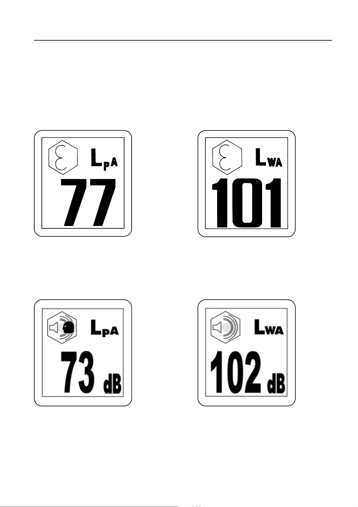
2.2 NOISE
PC130-6K + PC150LGP-6K
Valid until 31 december 2001
Operator ears noise value Ambient noise value
(Sound pressure level) (Sound power level)
2. SAFETY INFORMATION
95/27/EC
Noise level indicated is the guaranteed value as specified in the directive 86/662/EEC, as amended by 95/27/EC.
95/27/EC
Valid as of 1 January 2002
• Sound pressure level at the operator's station,
measured according to ISO6395 (Dynamic
test method, simulated working cycle)
• Sound power level emitted. This is the guaranteed value as specified in European directive
2000/14/EC.
2.3 VIBRATION
The weighted root mean square acceleration value to which the operator's
arms are subjected does not exceed 2.5 m/s
The weighted root mean square acceleration value to which the operator's
body is subjected does not exceed 0.5 m/s
These results were obtained by accelerometers during trench digging.
PC130/150LGP-6K ENG
2
2
0-3

3. INTRODUCTION
3.1 INTENDED USE
This Komatsu HYDRAULIC EXCAVATOR is designed to be used mainly for the following work:
• Digging work
• Smoothing work
• Ditching work
• Loading work
See the section "12.15 WORK POSSIBLE USING HYDRAULIC EXCAVATOR" for further details.
3.2 FEATURES
• This Komatsu HYDRAULIC EXCA V A T OR is equipped with various controls based on an advanced electronics
system.
° The monitor panel greatly facilitates daily maintenance and self-diagnosis.
° Working mode, active mode and travel speed are selectable.
° Digging and lifting force can be increased by light-touch control.
(For details, see operaton section).
• Adjustable wrist control levers make operations smooth and easy.
• Fresh filtered air heater assures comfortable operaton.
• Low noise level and smart urban-style design and coloring.
• Superb operating performance provided by powerful engine and high-performance hydraulic pumps.
• Low fuel consumption controlled by an electronic control system provides an environment-friendly machine.
3.3 BREAKING IN THE MACHINE
Your Komatsu machine has been thoroughly adjusted and tested before shipment.
However, operating the machine under severe conditions at the beginning can adversely affect the perform-
ance and shorten the life of the machine.
Be sure to break in the machine for the initial 100 hours (as indicated by the service meter).
During breaking in:
• Idle the engine for 5 minutes after starting it up.
• Avoid operation with heavy loads or at high speeds.
• Avoid sudden starts, sudded acceleration, sudden steering and sudded stops except in cases of emergency.
The precautions given in this manual for operating, maintenance and safety procedures are only those that
apply when this product is used for the specific purpose. If the machine is used for a purpose that is not listed in this
manual, Komatsu cannot bear any responsibility for safety. Alle consideration of safety in such operations is the
responsibility of the user.
Operations that are prohibited in this manual must never be carried out under any circumstances.
0-4
PC130/150LGP-6K ENG
4. LOCATION OF PLATES, TABLES TO ENTER SERIAL NO. AND DISTRIBUTOR
4. LOCATION OF PLATES, TABLES TO ENTER SERIAL NO.
AND DISTRIBUTOR
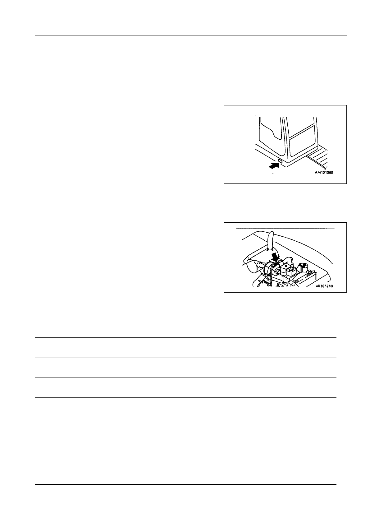
MACHINE SERIAL NO. PLATE POSITION
On the front bottom right of the operator’s cab
ENGINE SERIAL NO. PLATE POSITION
On the upper side of the engine cylinder head cover.
TABLE TO ENTER SERIAL NO. AND DISTRIBUTOR
Machine serial No.
Engine serial No.
Product Identification Number :
Manufacturers name: KOMATSU UK Ltd.
Address: Durham Road
Birtley
Chester-Le street
County Durham DH32QX
United Kingdom
Distributor
Address
Phone
0-5
4. LOCATION OF PLATES, TABLES TO ENTER SERIAL NO. AND DISTRIBUTOR
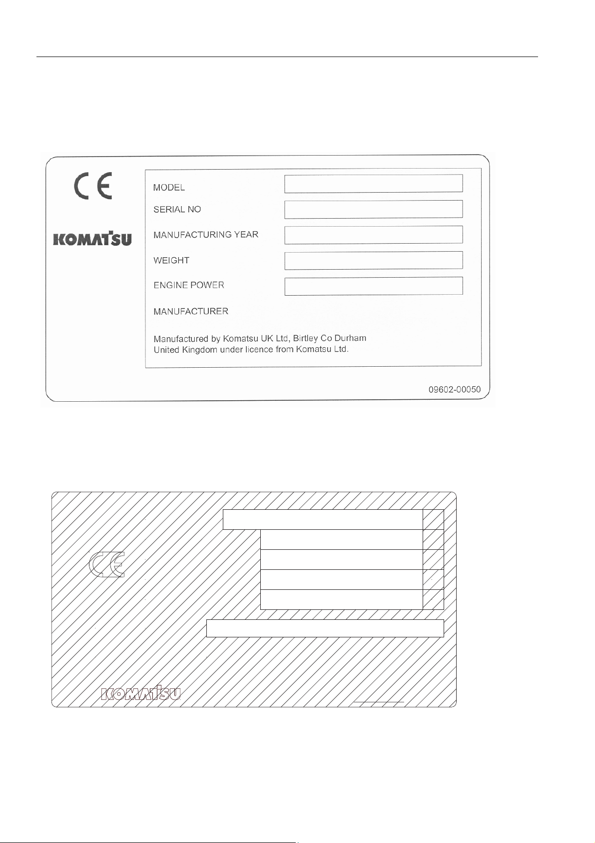
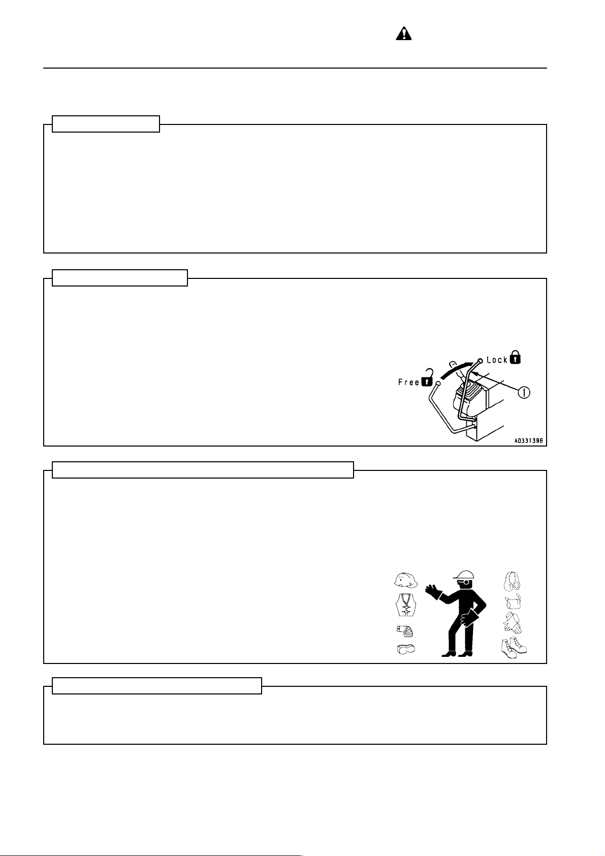
MACHINE SERIAL PLATE.
Valid until 31 December 2003
Valid as of 1 January 2004
MODEL
SERIALNo.
MANUFACT.YEAR
MASS
ENGINEPOWER
ProductIdentificationNumber
MANUFACTURER
kg
kW
ManufacturedbyKomatsuUKLtd.
forKomatsuLtd.,Tokyo,Japan
205-00-K1291
0-6

5. CONTENTS
1. Foreword.......................................................................................................................................... 0-1
2. Safety information .......................................................................................................................... 0-2
3. Introduction ..................................................................................................................................... 0-4
4. Location of plates, tabel to enter serial No. and distributor ....................................................... 0-5
SAFETY
6. General precautions ....................................................................................................................... 1-2
7. Precautions during operation........................................................................................................ 1-9
7.1 Before starting engine............................................................................................................ 1-9
7.2 After starting engine............................................................................................................... 1-11
7.3 Transportation........................................................................................................................ 1-18
7.4 Battery ................................................................................................................................... 1-19
7.5 Towing.................................................................................................................................... 1-21
7.6 Bucket with hook.................................................................................................................... 1-22
8. Precautions for maintenance......................................................................................................... 1-23
8.1 Before carrying out maintenance........................................................................................... 1-23
8.2 During maintenance............................................................................................................... 1-27
9. Position for attaching safety labels ................................................................................................... 1-32
9.1 Lifting capacity....................................................................................................................... 1-36
OPERATION
10. General view.................................................................................................................................... 2-2
10.1 General view of machine ....................................................................................................... 2-2
10.2 General view of controls and gauges .................................................................................... 2-3
11. Explanation of components........................................................................................................... 2-4
11.1 Machine monitor .................................................................................................................... 2-4
11.2 Switches ................................................................................................................................ 2-15
11.3 Control levers, pedals ............................................................................................................ 2-19
11.4 Ceiling window....................................................................................................................... 2-24
11.5 Front window ......................................................................................................................... 2-25
11.6 Door lock................................................................................................................................ 2-27
11.7 Cap, cover with lock............................................................................................................... 2-28
11.8 Luggage tray.......................................................................................................................... 2-29
11.9 Ashtray................................................................................................................................... 2-29
11.10 Car heater.............................................................................................................................. 2-30
11.11 Car radio................................................................................................................................ 2-32
11.12 Fuse....................................................................................................................................... 2-34
11.13 Fusible link............................................................................................................................. 2-34
11.14 Controllers ............................................................................................................................. 2-34
11.15 Tool box ................................................................................................................................. 2-34
11.16 Grease pump holder .............................................................................................................. 2-34
11.17 Refueling pump...................................................................................................................... 2-35
PC130/150LGP-6K ENG
0-7

5. CONTENTS
12. Operation ......................................................................................................................................... 2-36
12.1 Check before starting............................................................................................................. 2-38
12.2 Starting engine....................................................................................................................... 2-48
12.3 Operations and checks after starting engine ......................................................................... 2-51
12.4 Moving machine off................................................................................................................ 2-57
12.5 Steering machine................................................................................................................... 2-60
12.6 Stopping machine .................................................................................................................. 2-62
12.7 Swinging ................................................................................................................................ 2-63
12.8 Operation of work equipment................................................................................................. 2-64
12.9 Working mode selection ........................................................................................................ 2-65
12.10 Handling active mode ............................................................................................................ 2-67
12.11 Prohibitions for operation....................................................................................................... 2-69
12.12 Precautions for operation....................................................................................................... 2-71
12.13 Precautions when traveling up or down hills.......................................................................... 2-72
12.14 How to escape from mud....................................................................................................... 2-74
12.15 Work possible using hydraulic excavator............................................................................... 2-75
12.16 Replacement and inversion of bucket.................................................................................... 2-76
12.17 Parking machine .................................................................................................................... 2-78
12.18 Check after finishing work...................................................................................................... 2-79
12.19 Stopping engine..................................................................................................................... 2-80
12.20 Check after stopping engine .................................................................................................. 2-81
12.21 Locking .................................................................................................................................. 2-81
12.22 Overload warning device ....................................................................................................... 2-82
12.23 Offset boom ........................................................................................................................... 2-83
13. Transportation................................................................................................................................. 2-85
13.1 Loading, unloading work........................................................................................................ 2-85
13.2 Precautions for loading .......................................................................................................... 2-86
13.3 Precautions for transportation................................................................................................ 2-87
13.4 Lifting the machine................................................................................................................. 2-87
14. Cold weather operation .................................................................................................................. 2-92
14.1 Precautions for low temperature............................................................................................ 2-92
14.2 Precautions after completion of work..................................................................................... 2-94
14.3 After cold weather.................................................................................................................. 2-94
15. Long-term storage .......................................................................................................................... 2-95
15.1 Before storage ....................................................................................................................... 2-96
15.2 During storage ....................................................................................................................... 2-96
15.3 After storage .......................................................................................................................... 2-96
15.4 Starting machine after long-term storage .............................................................................. 2-96
16. Troubleshooting.............................................................................................................................. 2-97
16.1 When machine runs out of fuel .............................................................................................. 2-97
16.2 Phenomena that are not failures............................................................................................ 2-97
16.3 Method of towing machine..................................................................................................... 2-97
16.4 Using method for light-weight towing hook ............................................................................ 2-98
16.5 Precautions on particular jobsites.......................................................................................... 2-98
16.6 If battery is discharged........................................................................................................... 2-99
16.7 Other trouble.......................................................................................................................... 2-103
0-8
PC130/150LGP-6K ENG

5. CONTENTS
MAINTENANCE
17. Guides to maintenance .................................................................................................................. 3-2
18. Outlines of service.......................................................................................................................... 3-4
18.1 Outline of oil, fuel, coolant ..................................................................................................... 3-4
18.2 Outline of electric system....................................................................................................... 3-8
18.3 Outline of hydraulic system.................................................................................................... 3-9
19. Wear parts list ................................................................................................................................. 3-10
20. Use of fuel, coolant and lubricants according to ambient temperature .................................... 3-11
21. Standard tightening torques for bolts and nuts .......................................................................... 3-15
21.1 Introduction of necessary tools .............................................................................................. 3-15
21.2 Torque list .............................................................................................................................. 3-16
22. Periodic replacement of safety critical parts ............................................................................... 3-17
23. Maintenance schedule chart.......................................................................................................... 3-21
23.1 Maintenance schedule chart.................................................................................................. 3-21
23.2 Maintenance interval when using hydraulic breaker.............................................................. 3-23
24. Service procedure........................................................................................................................... 3-24
24.1 Initial 250 hours service ......................................................................................................... 3-24
24.2 When required ....................................................................................................................... 3-25
24.3 Check before starting............................................................................................................. 3-41
24.4 Every 50 hours service .......................................................................................................... 3-46
24.5 Every 100 hours service ........................................................................................................ 3-47
24.6 Every 250 hours service ........................................................................................................ 3-50
24.7 Every 500 hours service ........................................................................................................ 3-54
24.8 Every 1000 hours service ...................................................................................................... 3-60
24.9 Every 2000 hours service ...................................................................................................... 3-63
24.10 Every 4000 hours service ...................................................................................................... 3-65
24.11 Every 5000 hours service ...................................................................................................... 3-66
SPECIFICATIONS
25. Specifications.................................................................................................................................. 4-2
PC130/150LGP-6K ENG
0-9

5. CONTENTS
OPTIONS AND ATTACHMENTS
26. General Precautions .............................................................................................................................. 5-2
26.1 General precautions related to safety......................................................................................... 5-2
26.2 Precautions when installing attachments.................................................................................... 5-3
27. Handling bucket with hook ..................................................................................................................... 5-4
27.1 Checking for damage to bucket with hook.................................................................................. 5-4
27.2 Prohibited operations.................................................................................................................. 5-4
27.3 Precautions during operation...................................................................................................... 5-4
28. Machine ready for attachments.............................................................................................................. 5-5
28.1 Explanation of components ........................................................................................................ 5-5
28.2 Operation .................................................................................................................................... 5-7
28.3 Long-term storage ...................................................................................................................... 5-9
28.4 Specifications.............................................................................................................................. 5-9
29. Introduction of optianal parts and attachments .................................................................................... 5-10
29.1 Introduction of optianal parts and attachments......................................................................... 5-10
29.2 Attachment installation combination table .................................................................................5-11
29.3 Selection of track shoes............................................................................................................ 5-12
30. Extending machine service life ............................................................................................................ 5-14
30.1 Hydraulic breaker...................................................................................................................... 5-14
30.2 Power ripper ............................................................................................................................. 5-17
30.3 Fork grab .................................................................................................................................. 5-18
30.4 Grapple bucket ......................................................................................................................... 5-19
30.5 Scrap grapple ........................................................................................................................... 5-20
30.6 Crusher & cutter........................................................................................................................ 5-21
30.7 Hydraulic pile driver .................................................................................................................. 5-22
30.8 Hydraulic excavator with multi-purpose crane .......................................................................... 5-23
0-10
PC130/150LGP-6K ENG

SAFETY
PC130/150LGP-6K ENG
WARNING
Read and follow all safety precautions. Failure to do so may result in serious injury or death.
This safety section also contains precautions for optional equipment
and attachments.
1-1
WARNING: for reasons of
safety, always follow these
6 GENERAL PRECAUTIONS
safety precautions.
SAFETY RULES
• Only trained and authorised personnel can operate and maintain the machine.
• Follow all safety rules, precautions and instructions when operating or performing maintenance on the machine.
• Do not operate the machine of you are not feeling well, or if you are taking medicine which will make you
sleepy, or if you have been drinking. Operating in such condition will adversely affect your judgement and
may lead to an accident.
• When working with another operator of with a person on worksite traffic duty, be sure that all personnel
understand all hand signals that are to be used.
• Always follow all rules related to safety .
SAFETY FEATURES
• Be sure that all guards and covers are in their proper position. Have guards and covers repaired if damaged.
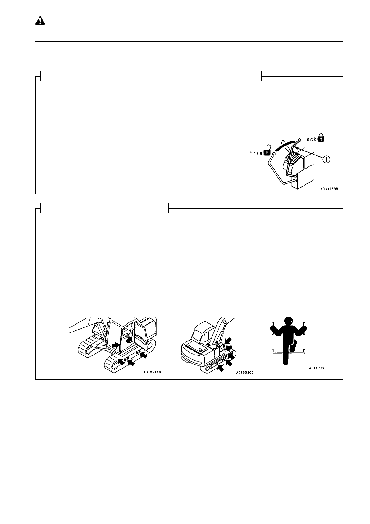
• Use safety features such as safety lock levers 햲 properly .
• Never remove any safety features. Always keep them in good operating condition.
Safety lock lever see "12.17 PARKING MACHINE".
• Improper use of safety features could result in serious bodily injury or death.
CLOTHING AND PERSONAL PROTECTIVE ITEMS
• Avoid loose clothing, jewelery , and loose long hair . They can catch on controls or in moving parts and cause
injury or death.
• Also, do not wear oily clothes, because they are flammable.
• Wear a hard hat, safety glasses, safety shoes, mask or gloves wehn operating or maintaining the machine.
Always wear safety goggles, hard hat and heavy gloves if your job involves scattering metal chips or minute
materials particularly when driving pins with a hammer and when cleaning the air cleaner element with
compressed air. Check also that there is no one near the machine.
• Check that all protective equipment functions properly before using.
UNAUTHORIZED MODIFICA TION
Any modification made without authorization from Komatsu can create hazards. Before making a modification,
consult your Komatsu distributor. Komatsu will not be responsible for any injury or damage caused by any
unauthorized modification.
1-2
PC130/150LGP-6K ENG
WARNING: Failure to follow
these safety precautions may
lead to a serious accident.
6 GENERAL PRECAUTIONS
ALWA YS APPLY LOCK WHEN LEAVING OPERATOR'S SEAT
• When standing up from the operator's seat, always place the safety lock levers 햲 securely in the LOCK
position. If you accidentally touch the levers when they are not locked, the work equipment may suddenly
move and cause serious injury or damage.
• When leaving the machine, lower the blade and ripper completely to the ground, set the safety lock levers 햲
to the LOCK position, then stop the engine. Use the key to lock alle the equipment.
Always remove the key and take it with you.
Work equipment posture see "12.17 PARKING MACHINE".
Locking see "12.21 LOCKING"
MOUNTING AND DISMOUNTING
• Never jump on or off the machine. Never get on or off a moving machine.
• When getting on or off the machine, always face the machine and use the handrails and steps.
• Never hold any control levers or lock levers when getting on or off the machine.
• To ensure safety, always maintain three-point contact (both feet and one hand, or both hands and one foot)
with the handrails and steps to ensure that you support yourself.
• If there is anyu oil, grase, or mud on the handrails or steps, wipe it off immediately . Always keep these parts
clean. Repair any damage and tighten any loose bolts.
• When getting on or off the machine, or when moving along the top of the track, if you hold the handrail inside
the door when moving on top of the track shoe, and the door lock is not locked securely , the door may move
and cause you to fall.
Always lock the door securely .
Method of locking door see "11.6 DOOR LOCK"
PC130/150LGP-6K ENG
1-3
WARNING: for reasons of
safety, always follow these
6 GENERAL PRECAUTIONS
safety precautions.
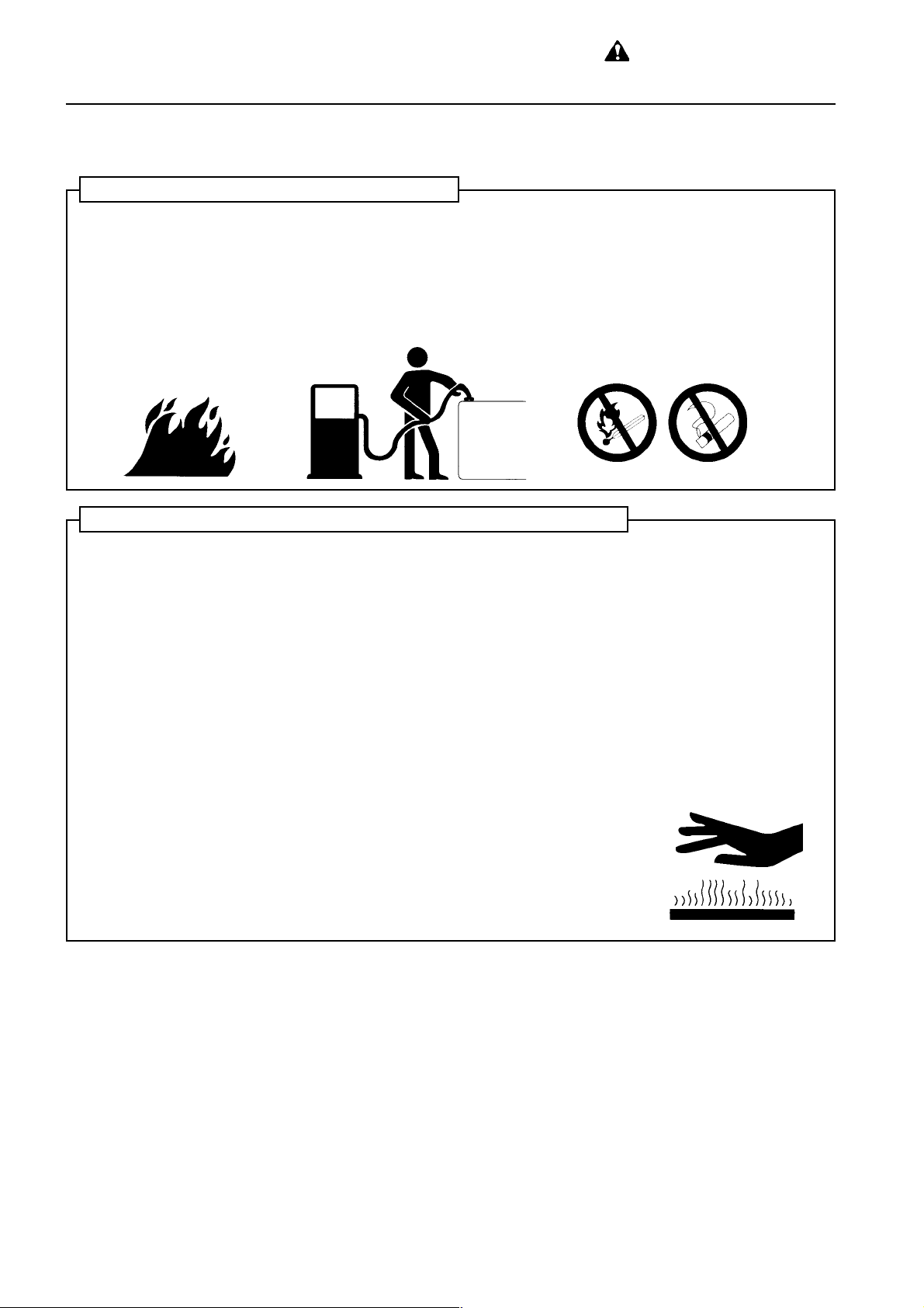
FIRE PREVENTION FOR FUEL AND OIL
Fuel, oil, and antifreeze can be ignited by a flame. Fuel is particularly flammable and can be hazardous.
Always observe the following:
• Keep any flame or lighted cigarette away form flammable fluids.
• Stop the engine and do not smoke when refueling
• Tighten all fuel and oil caps securely
• Use well-ventilated areas for adding or storing oil and fuel.
• Keep oil and fuel in the determined place and do not allow unauthorized persons to enter.
PRECAUTIONS WHEN HANDLING AT HIGH TEMPERATURE
• Immediately after operations are stopped, the engine oil and hydraulic oil are at high temperature and are
still under pressure. Attempting to remove the cap, drain the oil or water, or replace the filters may lead to
serious burns. Always wait for the temperature to go down, and follow the specified procedures when carrying out these operations.
• T o prevent hot water from spurting out, stop the engine, wait for the water to cool, then loosen the cap slowly
to relieve the pressure before removing the cap.
(When checking if the water temperature has gone down, put your hand near the front face of the radiator
and check the air temperature. Be careful not to touch the radiator).
• To prevent hot oil from spurting out, stop the engine, wait for the oil to cool, then loosen the cap slowly to
relieve the pressure before removing the cap.
(When checking if the oil temperature has gone down, put your hand near the front face of the hydraulic tank
and check the air temperature. Be careful not to touch the hydraulic tank).
1-4
PC130/150LGP-6K ENG
WARNING: Failure to follow
these safety precautions may
lead to a serious accident.
6 GENERAL PRECAUTIONS
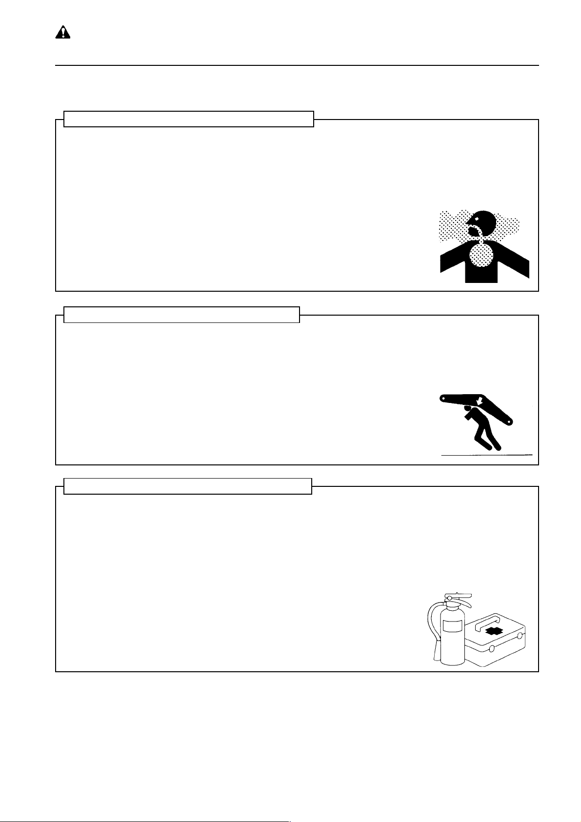
ASBESTOS DUST HAZARD PREVENTION
Asbestos dust can be hazardous to your health if it is inhaled.
Komatsu does not use asbestos in its products, but if you handle materials containing asbestos fibers, follow
the guidelines given below:
• Never use compressed air for cleaning.
• Use water to keep down the dust when cleaning
• If there is danger that there may be asbestos dust in the air, operate the machine from an upwind position
whenever possible.
• Use an approved respirator if necessary .
CRUSHING OR CUTTING PREVENTION
Do not enter, or put your hand or arm or any other part of your body between movable parts such as the work
equipment and cylinders, or between the machine and work equipment.
If the work equipment is operated, the clearance will change and this may lead to serious damage or personel
injury.
If it is necessary to go between movable parts, always lock the levers and be sure that the work equipment
cannot move. For details, see "8. PRECAUTIONS FOR MAINTENANCE".
FIRE EXTINGUISHER AND FIRST AID KIT
Always follow the precautions below to prepare for acton if any injury or fire should occur.
• Be sure that fire extinguishers have been provided and read the labels to ensure that you know how to use
them.
• Provide a first aid kit at the storage point. Carry out periodic checks and add to the contents if necessary.
• Know what to do in the event of a fire or injury.
• Decide which phone numbers of persons (doctor, ambulance, fire station etc.) to contact in case of an
emergency. Post these contact numbers in specified places and make sure that all personnel know the
numbers and correct contact procedures.
PC130/150LGP-6K ENG
1-5
WARNING: for reasons of
safety, always follow these
6 GENERAL PRECAUTIONS
safety precautions.
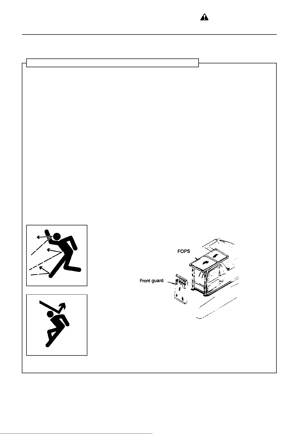
PROTECTION AGAINST FALLING OR FLYING OBJECTS
If there is any danger of falling or flying objects hitting the operator, install protective guards in place to protect
the operator as required for each particular situation.
• For work with breakers, install a front guard on the windshield. Also, place a laminate coating sheet over the
windshield.
• For demolition of shear workk, install a front guard on the windshield and a top guard on the cab. Also, place
a laminate coating sheet over the windshield.
• For work in mines, quarries, demolition, tunnels or other places where there is danger of falling rocks, put
FOPS (falling object protective structure) in place. Also, place a laminate coating sheet over the windshield.
The above comments are made with regards to typical working conditions. By all means you should put on
other guards if required by conditions at your particular site.
For details of safety guards, please contact your Komatsu distributor.
Also, even for other types of work, if there is any danger of being hit by falling or flying objects or of objects
entering the operator's cab, select and install a guard that matches the working conditions.
Be sure to close the front window before commencing work.
When carrying out the above operations, make sure to keep all persons other than the operator outside that
range of falling or flying objects. Be particularly sure to maintain a proper distance when carrying out shear
operations
1-6
PC130/150LGP-6K ENG
WARNING: Failure to follow
these safety precautions may
lead to a serious accident.
6 GENERAL PRECAUTIONS
PRECAUTIONS FOR ATTACHMENTS
• When installing and using an optional attachment, read the instruction manual for the attachment and the
information related to attachments in this manual.
• Do not use attachments that are not authorized by Komatsu or your Komatsu distributor. Use of unauthorized attachments could create a safety problem and adversely affect the proper operation and useful lif of
the machine.
• Any injuries, accidents, product failures resulting from the use of unauthorized attachments will not be the
responsibility of Komatsu.
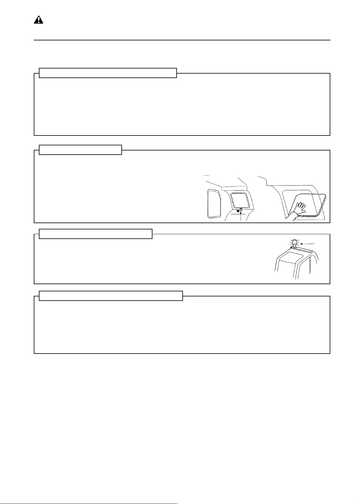
ERMERGENCY EXIT
• When exit by normal means is prevented in an emergency you can
get out through the emergency exit (rear window).
• Pull the ring at the bottom of the window and remove strip. This will
allow you to push out the glass.
ROT A TING BEACON (OPTION)
• When the machine is operated on or beside a road, a rotating beacon is required to avoid a traffic accident
• Contact your Komatsu distributor to install a beacon lamp.
ELECTROMAGNETIC INTERFERENCE
When this machine is operating close to a source of high electromagnetic interference, such as a radar
station, some abnormal phenomena may be observed.
• The display on the monitor panel may behave erratically
• The warning buzzer may sound
These effects do not signify a malfunction and the machine will return to normal as soon as the source of
interference is removed.
PC130/150LGP-6K ENG
1-7
WARNING: for reasons of
safety, always follow these
6 GENERAL PRECAUTIONS
safety precautions.
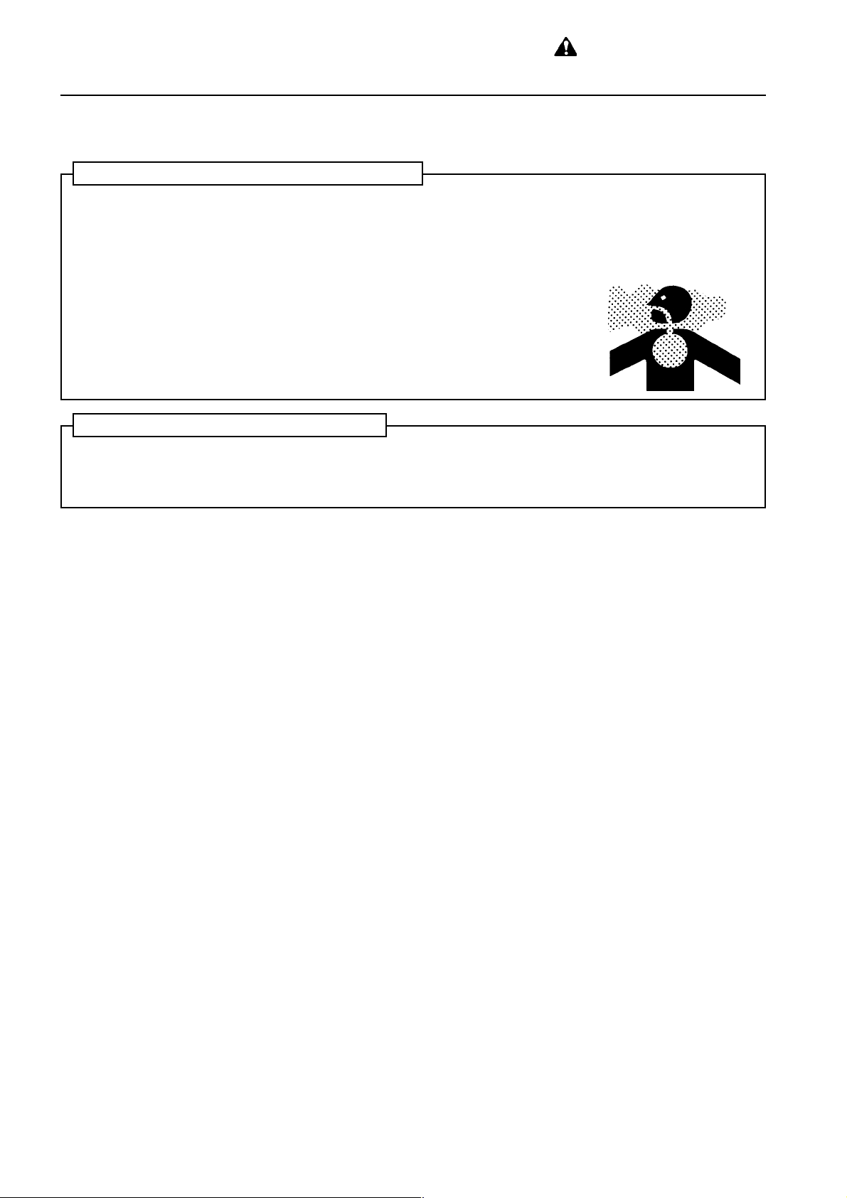
VENTILATION FOR ENCLOSED AREAS
Exhaust fumes from the engine can kill.
• If it is necessary to start the engine within an enclosed area, or you handle fuel, flushing oil, or paint, open
the doors and windows to ensure that you provide adequate ventilation to prevent gas poisoning.
• If opening the doors and windows still does not provide adequate ventilation, set up fans.
PRECAUTIONS WITH CAB GLASS
If by mistake the cab glass on the work equipment side should crack, there is danger of direct contact between
the operator's body and the work equipment. This is extremely dangerous.
If the glass is cracked, stop operations immediately and replace the glass.
1-8
PC130/150LGP-6K ENG
7. PRECAUTIONS DURING
OPERATION
WARNING: Failure to follow
these safety precautions may
lead to a serious accident.
7.1 BEFORE STARTING ENGINE
SAFETY A T WORKSITE
• Before starting operations, thoroughly ckeck the area for any unusual conditions that could be dangerous.
• Check the terrain and condition of the ground at the worksite, and determine the best and safest method of
operation.
• Make the ground surface as hard and horizontal as possible before carrying out operations.
If the jobsite is dusty , spray water before starting operations.
• If you need to operate on a road, protect pedestrians and cars by designating a person for worksite traffic
duty or by installing fences and putting up NO ENTRY signs around the worksite.
• If water lines, gas lines, or high-voltage electrical lines may be buried under the worksite, contact each utility
and identify their locations. Be careful not to sever of damage any of these lines.
• Check the ground condition and the depth and flow of water before operating in water or crossing a river.
NEVER be in water which is in excess of the permissible water depth.
Permissible water depth see "12.12 PRECAUTIONS FOR OPERATION"
CHECKS BEFORE STARTING ENGINE
Carry out the following checks before starting the engine at the beginning of the days work.
Failure to carry out these checks may lead to serious injury or damage.
• Completely remove all flammable materials accumulated around the engine and battery, returm all fuel
containers to teir propeer place, remove all parts and tools from the operator's compartment, and remove
any dirt from the mirrors, handrails, and steps.
Walk-around checks see "12.1.1 WALK AROUND CHECK".
• check the coolant level, fuel level, and oil level in the hydraulic tank, check for clogging of the air cleaner, and
check the electric wiring.
Checks before starting see "12.1.2 CHECK BEFORE STARTING"
• Adjust the operator's seat to a positions where it is easy to carry out operations, and check for wear or
damage to the seat belt and seat belt mounting equipment.
Adjusting operator's seat see "12.1.3 ADJUSTING BEFORE STARTING OPERATION".
• Check that the gauges work properly, and check that the control levers are all at the NEUTRAL position.
Method of checking operation of gauges
see "12.1.4 OPERATIONS AND CHECKS BEFORE STARTING ENGINE".
• If any of the mirrors are broken, replace them with new ones.
• When removing and installing the mirrors for replacement or transportation - see "13.3 PRECAUTIONS
FOR TRANSPORT ATION".
• Check that the mirrors and window glass provide a clear view.
If the above inspections show any abnormality, carry out repairs immediately.
PC130/150LGP-6K ENG
1-9
WARNING: for reasons of
safety, always follow these
7. PRECAUTIONS DURING OPERA TION
safety precautions.
WHEN ST ARTING ENGINE
• Walk around your machine again just before mounting it, and check for people and objects that might be in
the way .
• Never start the engine if a warning tag has been attached to the work equipment control lever.
• When starting the engine, sound the horn as an alert.
• Start and operate the machine only while seated.
• An additional worker may ride in the machine only when sitting in the passenger seat, if fitted. Do not allow
anyone to ride on the machine body .
• Do not short circuit the starting motor circuit to start the engine. It is not only dangerous, but will also cause
damage to the equipment.
1-10
PC130/150LGP-6K ENG
WARNING: Failure to follow
these safety precautions may
lead to a serious accident.
7. PRECAUTIONS DURING OPERA TION
7.2 AFTER STARTING ENGINE
CHECKS AFTER STARTING ENGINE
Failure to carry out the checks properly after starting the engine will lead to delays in discovery of abnormalities, and this may lead to serious injury or damage to the machine.
When carrying out the checks, use a wide area where there are no obstructions. Do not allow anyone near the
machine.
• Check the operation of the gauges and equipment, and check the operation of the blade, ripper, brakes,
travel system, and steering system.
• Checks for any abnormality in the sound of the machine, vibration, heat, smell, or gauges; check also that
there is no leakage of air, oil, or fuel.
• If any abnormality is found, carry out repair immediately.
If the machine is used when it is not in proper condition, it may lead to serious injury or damage to the
machine.
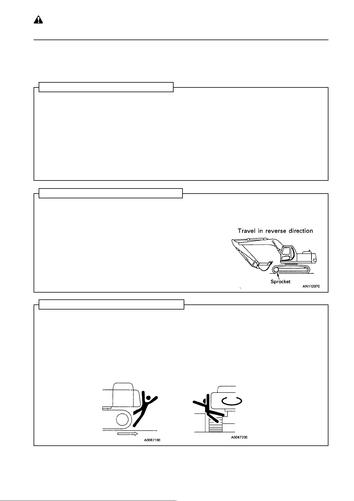
PRECAUTIONS WHEN ST ARTING OFF
Check the direction of the track frame before operating the travel lever.
• When the sprocket is at the front, the operaton of the travel lever is
reversed, so operate the machine carefully .
Method of steering machine see "12.4 MOVING MACHINE
OFF".
Before moving the machine off, check again that there are no persons or obstacles in the surrounding area.
• When moving the machine off, sound the horn to warn people in the
surrounding area.
• Always sit in the operator's seat when driving the machine.
• Always close the door of the operator' cab and check that the door is
locked in position securely .
CHECK WHEN CHANGING DIRECTION
To prevent serious injury or death, always do the following before moving the machine or doing the levelling
work.
• Before changing between forward and reverse, reduce speed and stop the machine.
• Before operating the machine, sound the horn to warn people in the area.
• Check that there is no one near the machine. Be particularly careful to check behind the machine.
• When operating in areas that may be hazardous or have poor visibility , designate a person to direct worksite
traffic.
• Ensure that no unauthorized person can come within the direction of turning or direction of travel.
Always be sure to carry out the above precautions even when the machine is equipped with a backup alarm
and mirrors.
PC130/150LGP-6K ENG
1-11
WARNING: for reasons of
safety, always follow these
7. PRECAUTIONS DURING OPERA TION
safety precautions.
PRECAUTIONS WHEN TRA VELLING
• Never turn the key in the starting switch to the OFF position when travelling.
It is dangerous if the engine stops when the machine is travelling, because it becomes impossible to operate
the steering.
• It is dangerous to look around you when operating. Always concentrate on your work.
• It is dangerous to drive too fast, or to start suddenly, stop suddenly, turn sharply or zigzag.
• If you find any abnormality in the machine during operation (noise, vibration, smell, incorrect gauges, air
leakage, oil leakage, etc.) move the machine immediately to a safe place and look for the cause.
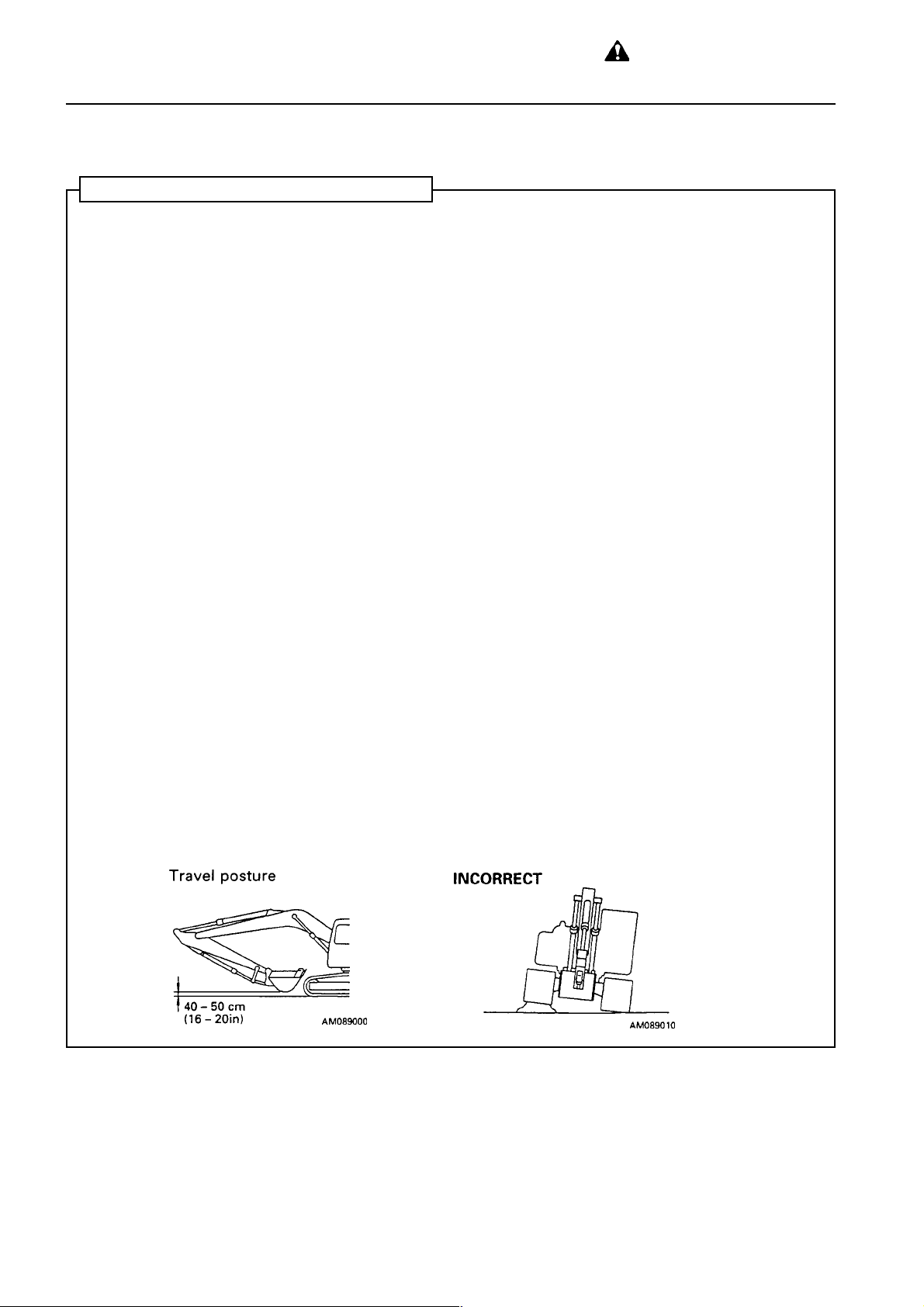
• Set the work equipment to a height of 40 - 50 cm from the ground level and travel on level ground.
• When travelling do not operate the work equipment control levers. If the work equipment control levers have
to be operated, never operate them suddenly .
• Do not operate the steering suddenly. The work equipment may hit the ground surface and cause the machine to lose its balance, or may damage the machine or structures in the area.
• When travelling on rough ground, travel at low speed, and avoid sudden changes in direction.
• Avoid travelling over obstacles as far as possible. If the machine has to travel over an obstacle, keep the
work equipment as close to the ground as possible and travel at low speed. Never travel over obstacles
which make the machine tilt strongly (10° or more).
• When travelling or carrying out operations, always keep your distance from other machines or structures to
avoid coming into contact with them.
• NEVER be in water which is in excess of the permissible water depth.
Permissible water depth see "12.12 PRECAUTIONS FOR OPERATON".
• When passing over bridges or structures on private land, check first that the structure is strong enough to
support the mass of the machine. When travelling on public roads, check first with the relevant authorities
and follow their instructions.
1-12
PC130/150LGP-6K ENG
WARNING: Failure to follow
these safety precautions may
lead to a serious accident.
7. PRECAUTIONS DURING OPERA TION
TRAVELLING ON SLOPES
• Travelling on slopes could result in the machine tipping over or slipping to the side.
• When travelling on slopes, keep the blade approximately 20 - 30 cm above the ground. In case of emergency, quickly lower the bucket to the ground to help the machine to stop.
• Do not turn on slopes or travel across slopes. Always go down to a flat place to perform these operations.
Method of travelling on slopes See "12.13 PRECAUTIONS WHEN TRA VELLING UP OR
DOWN HILLS".
• Do not travel on grass, fallen leaves or wet steel plates. Even slight slopes may cause the machine to slip to
the side, so travel at low speed and make sure that the machine is always travelling directly up or down the
slope.
• If the engine stops on a slope, place the travel lever at the neutral position and lower the bucket to the
ground. Do not operate the steering. There is danger that the machine will turn under its own weight.
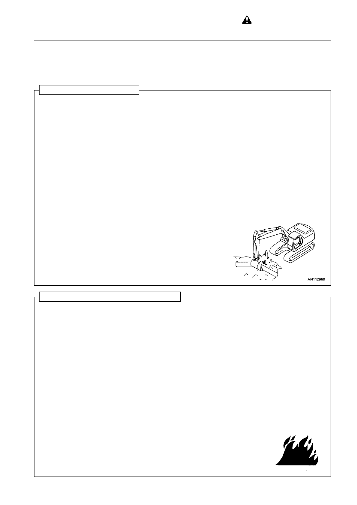
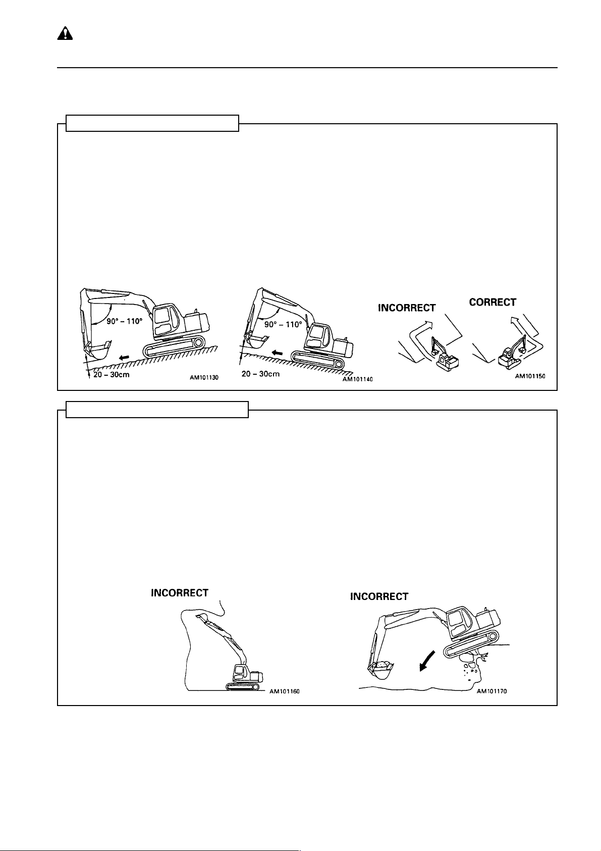
PROHIBITED OPERA TIONS
• Do not dig the work face under an overhang. This may cause the overhang to collapse and fall on top of the
machine.
• Do not carry out deep digging under the front of the machine. The ground under the machine may collapse
and cause the machine to fall. Take emergencies into consideration and set with the travel motor at the rear
and the track (undercarriage) at right angles to the road shoulder before digging to enable the machine to
move back quickly . If the ground under the machine collapses and there is no time to drive in reverse, do not
suddenly raise the arm and boom. In some cases, it may in fact be safer to lower the arm and boom.
• Do not swing the work equipment to the side when it is carrying a heavy load. The stability to the side is less
than the stability to the front, so there is danger that the machine may turn over.
• Limits on use.
To prevent accidents caused by breakage of the work equipment or tipping over of the machine under
excessive load, do not use the machine in excess of its capacity . Always be sure to keep within the maximum
specified load and safe angle determined for the structure.
PC130/150LGP-6K ENG
1-13
WARNING: for reasons of
safety, always follow these
7. PRECAUTIONS DURING OPERA TION
safety precautions.
PRECAUTIONS WHEN OPERA TING
• Be careful not to approach too close to the edge of cliffs.
• Carry out only work that is specified as the purpose of the machine.
Carrying out other operations will cause breakdowns.
Specified operations See "WORK POSSIBLE USING HYDRAULIC EXCAVATOR".
• Do the following to ensure good visibility.
• When operating in dark places, turn on the working lamps and front lamps, and install lighting at the job
site if necessary.
• Do not carry out operations in fog, mist, snow or heavy rain or other conditions where the visibility is
poor. Wait for the weather to clear so that visibility is sufficient to carry out work.
• Always do as follows to prevent the work equipment from hitting other objects.
• When operating in tunnels, under bridges, under electric wires, or other places where the height is
limited, be extremely careful not to let the bucket, boom, or arm hit anything.
• To prevent accidents caused by hitting other objects, always operate the machine at a speed which is
safe for operation, particularly in confined spaces, indoors, and in places where there are other machines.
• Never pass the bucket over the head of any worker or over the operator's cab on a dump truck.
1-14
PC130/150LGP-6K ENG
WARNING: Failure to follow
these safety precautions may
lead to a serious accident.
7. PRECAUTIONS DURING OPERA TION
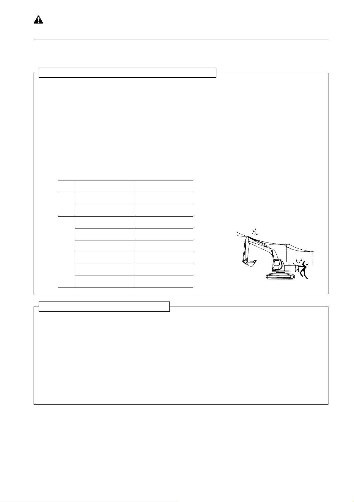
DO NOT GO CLOSE TO HIGH-VOL TAGE CABLES
• Do not let the machine touch overhead electric cables. Even going close to high-voltage cables can cause
electric shock. Always maintain the safe distance given below between the machine and the elctric cable.
• To prevent accidents, always do as follows.
• On job sites where there is danger that the machine may touck the electric cables, consult the electricity
company before starting operations to check that the actions determined by the relevant laws and
regulations have been taken.
• Wear rubber shoes and gloves. Lay a rubber sheet on top of the operator's seat, and be careful not to
touch the chassis with any exposed part of your body.
• Use a signalman to give worning if the machine approaches too close to the electric cables.
• If the work equipment should touch the electric cable,the operator should not leave the operator's com-
partment.
• when carrying out operations near high voltage cables, do not let anyone come close to the machine.
• Check with the electricity company about the voltage of the cables before starting operations.
egatloVecnatsidytefas.niM
V002•001m2
Low
voltage
V006.6m2
V000.22m3
V000.66m4
V000.451m5
V000.781m6
Very high voltage
V000.572m7
V000.005m11
OPERA TE CAREFULLY ON SNOW
• When working ons now or icy roads, even a slight slope may cause the machine to slip to the side, so always
travel at low speed and avoid sudden starting, stopping, or turning. There is danger of slipping particularly on
uphill or downhill slopes.
• With frozen road surfaces, the ground becomes soft when the temperature rises, so the travel conditions
become unstable. In such cases be extremely careful when travelling.
• When there has been heavy snow, the road shoulder and objects placed beside the road are buried in the
snow and cannot be seen, so always carry out operations carefully.
When travelling on snow-covered slopes, never apply the brakes suddenly . Reduce the speed and use the
engine as a brake while applying the foot brake intermittently (depress the brake intermittently several
times). If necessary , lower the bucket to the ground to stop the machine.
• The load varies greatly according to the characteristics of the snow, so adjust the load accordingly and be
careful not to let the machine slip.
PC130/150LGP-6K ENG
1-15
WARNING: for reasons of
safety, always follow these
7. PRECAUTIONS DURING OPERA TION
safety precautions.
WORKING ON LOOSE GROUND
• Do not operate the machine on soft ground. It is difficult to get the machine out again.
• Avoid operating your machine too close to the edge of cliffs, overhangs, and deep ditches. If these areas
collapse under the mass or vibration of your machine it could fall or tip over and this could result in serious
injury or death. Remember that the soil after heavy rain, blasting or earthquakes is weakened in these areas.
• Earth laid on the ground and the soil near ditches is loose. It can collapse under the mass or vibration of your
machine and cause your machine to tip over.
• Install the head guard (FOPS) when working in areas where there is danger of falling stones.
• Install the ROPS and wear the seat belt when working in areas where there is danger of falling rocks or of the
machine turning over.
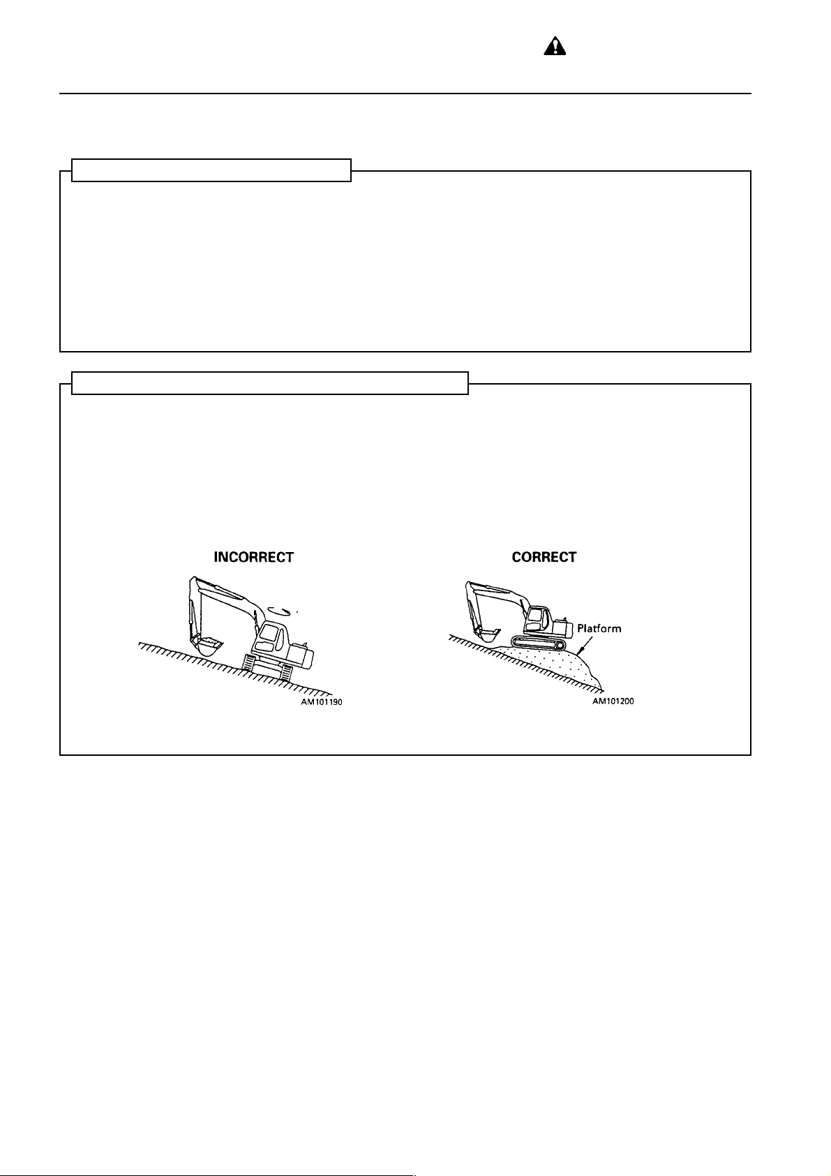
PRECAUTIONS WHEN WORKING ON SLOPES
• When working on slopes, there is danger that the machine may lose its balance and turn over when the
swing or work equipment are operated. Always carry out these operations carefully.
• Do not swing the work equipment from the uphill side to the downhill side when the bucket is loaded. This
operation is dangerous.
• If the machine has te be used on a slope, pile the soil to make a platform that will keep the machine as
horizontal as possible.
Piled soil on slope See "12.13 PRECAUTIONS WHEN TRAVELLING UP OR DOWN HILLS".
1-16
PC130/150LGP-6K ENG
WARNING: Failure to follow
these safety precautions may
lead to a serious accident.
7. PRECAUTIONS DURING OPERA TION
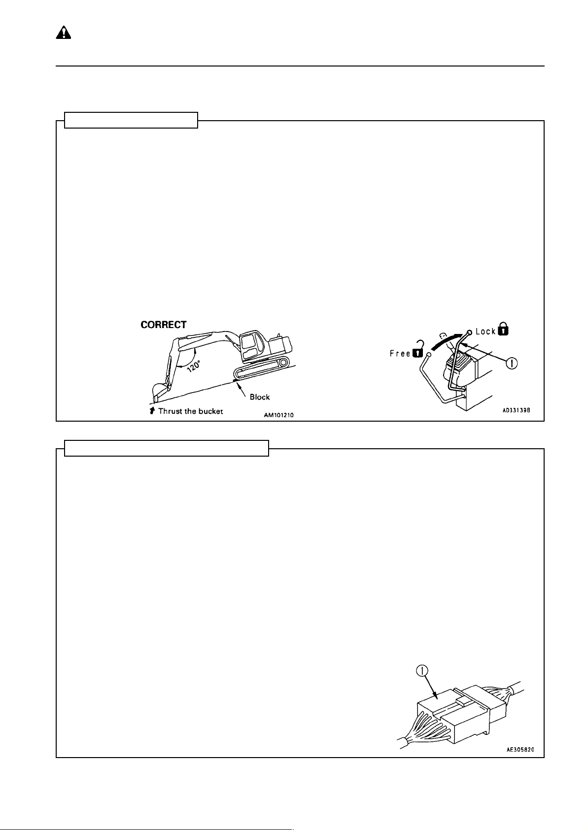
P ARKING MACHINE
• Park the machine on level ground where there is no danger of falling rocks or landslides, or of flooding if the
land is low, and lower the work equipment to the ground.
• If it is necessary to park the machine on a slope, set blocks under the tracks to prevent the machine from
moving, then dig the work equipment into the ground.
• After stopping the engine, operate the right work equipment control lever several times to the RAISE and
LOWER positions te release the remaining pressure in the hydraulic circuit.
• When parking on public roads, provide fences, signs, flags or lights and put up any other necessary signs to
ensure that passing traffic can see the machine clearly , and park the machine so that the machine, flags and
fences do not obstruct traffic.
Parking procedure See "12.17 PARKING MACHINE".
• When leaving the machine, set the safety lock lever 햲 to the LOCK position, stop the engine, and use the
key to lock all the equipment. Always remove the key and take it with you.
Work equipment posture See 12.17 PARKING MACHINE".
Locks See "12.21 LOCKING".
• Always close the door of the operator's compartment.
PRECAUTIONS IN COLD AREAS
• After completing operations, remove all water, snow, or mud stuck to the wiring harness, connector 햲,
switches, or sensors, and cover these parts.
If the water freezes, it will cause malfunctions of the machine when it is next used, which may lead to
unexpected accidents.
• Carry out the warming-up operation thoroughly. If the machine is not thoroughly warmed up before the
control levers are operated, the reaction of the machine will be slow, and this may lead to unexpected
accidents.
• Operate the control levers to relieve the hydraulic pressure (raise to above the set pressure for the hydraulic
circuit and release the oil to the hydraulic tank) to warm up the oil in the hydraulic circuit. This ensures good
response from the machine and prevents malfunctions.
• If the battery electrolyte is frozen, do not charge the battery of start the engine with a different power source.
There is danger that this will ignite the battery.
When charging or starting the engine with a different power source, melt the battery electrolyte and check
for leakage of battery electrolyte before starting.
Battery charge rate See "COLD WEA THER OPERATION".
PC130/150LGP-6K ENG
1-17
WARNING: for reasons of
safety, always follow these
7. PRECAUTIONS DURING OPERA TION
safety precautions.
7.3 TRANSPORTATION
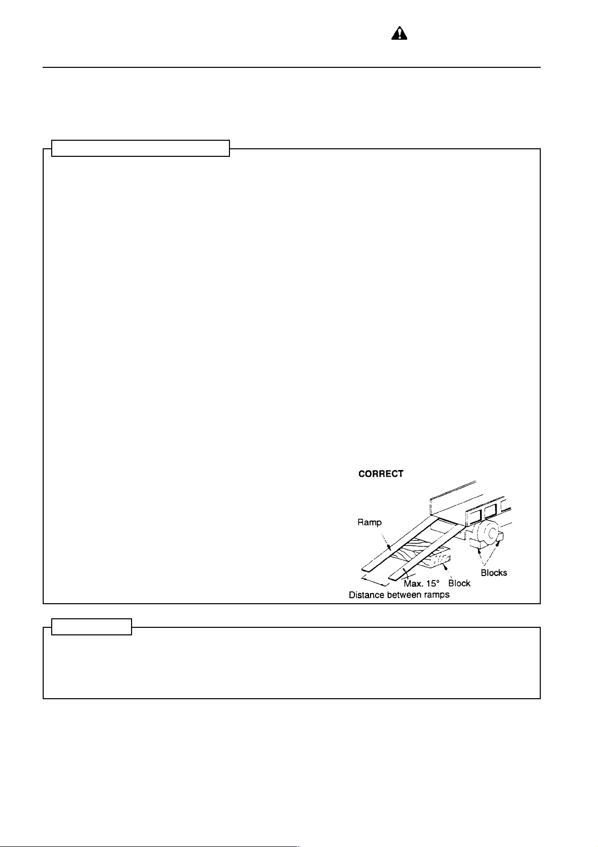
LOADING AND UNLOADING
• Loading and unloading the machine always involves potential hazards. EXTREME CAUTION SHOULD BE
USED.
When loading or unloading the machine, run the engine at low idling and travel at low speed.
• Perform loading and unloading on firm, level ground only . Maintain a safe distance from the edge of a road.
• ALWAYS block the wheels of the hauling vehicle and place blocks under both ramps before loading and
unloading.
• ALWAYS use ramps of adequate strenght. Be sure the ramps are wide and long enough to provide a safe
loading slope.
• Be sure that the ramps are securely positioned and fastened, and that the two sides are at the same level as
one another.
• Be sure the ramp surface is clean and free of grease, oil, ice and loose materials. Remove dirt from the
machine tracks.
• NEVER correct your steering on the ramps. If necessary drive away from the ramps and climb again.
• Swing the upper structure with extreme care on the trailer to avoid a possible accident caused by body
instability.
. After loading, block the machine tracks and secure the machine with tie-downs.
Loading and unloading See "13 TRANSPORT A TION"
Tie-downs See "13 TRANSPORTATION"
SHIPPING
• When shipping the machine on a hauling vehicle, obey all state and local laws governing the weight, width,
and length of a load. Also obey all applicable traffic regulations.
• Determine the shipping route while taking into account the width, height and weight of the load.
1-18
PC130/150LGP-6K ENG

WARNING: Failure to follow
these safety precautions may
lead to a serious accident.
7. PRECAUTIONS DURING OPERA TION
7.4 BATTERY
BA TTERY HAZARD PREVENTION
Battery electrolyte contains sulphuric acid, and batteries generate hydrogen gas, so mistaken handling can
lead to serious injury or fire. For this reason, always observe the following precautions.
• Never bring any lighted cigarette or flama near the battery.
• When working with batteries, ALWAYS war safety glasses and rubber gloves.
• If you spill acid on your clothes or skin, immediately flush the area with large amounts of water.
• Battery acid could cause blindness if splashed into the eyes. If acid gets into your eyes flush them immediately with large quantities of water and see a doctor at once.
• If you accidentally drink electrolyte, drink a large quantity of water or milk, beaten egg or vegetable oil. Call
a doctor or poison prevention center immediately .
• Before working with batteries, stop the engine and turn the starting switch to the OFF position.
• Avoid short-circuiting the battery terminals (between the positive + terminal and negative - terminal)
through accidental contact with metal objects such as tools.
• When installing the battery , connect the positive + terminal first, and when removing the battery , disconnect
the negative - terminal (ground side) first.
• When removing or installing, check which is the positive + terminal and negative - terminal, and tighten the
nuts securely .
If the battery electrolyte is near the LOWER LEVEL, add distilled water. Do not add distilled water above the
UPPER LEVEL.
• When cleaning the top surface of the battery, wipe it with a damp cloth. Never use gasoline, thinner or any
other organic solvent or cleaning agent.
• Tighten the battery caps securely.
• If the battery electrolyte is frozen, do not charge the battery of start the engine with a different power source.
There is danger that this will ignite the battery.
When charging or starting the engine with a different power source, melt the battery electrolyte and check
for leakage of battery electrolyte before starting.
• Always remove the battery from the chassis before charging it
PC130/150LGP-6K ENG
1-19

WARNING: for reasons of
safety, always follow these
7. PRECAUTIONS DURING OPERA TION
safety precautions.
ST ARTING WITH BOOSTER CABLES
If any mistake is made in the method of connecting the booster cables, it may cause a fire, so always do as
follows.
• Carry out the starting operation with two workers (with one worker sitting in the operator's seat).
• When starting from another machine, do not allow the two machines to touch.
• When connecting the booster cables, turn the starting switch OFF for both the normal machine and problem
machine.
• Be sure to connect the positive + cable first when installing the booster cables. Disconnect the ground or
negative - cable first when removing them.
• The final ground connection is the connection of the ground to the engine block of the problem machine.
However, this will cause sparks, so be sure to connect it as far as possible from the battery.
Starting procedure when using booster cables See "16.5 IF BATTERY IS DISCHARGED".
• When removing the booster cables, be careful not to let the booster cable clips touch each other or to let the
clips touch the machine.
INCORRECT
CHARGING BA TTERY
If the battery is handled incorrectly when it is being charged, there is danger that the battery may explode, so
follow the instructions in HANDLING BATTERY and in the instruction manual for the charger, and always
observe the following precautions.
• Carry out the charging in a well-ventilated place, and remove the battery caps. This disperses the hydrogen
gas and prevents explosion.
• Set the voltage on the cherger to match the voltage on the battery to be charged. If the voltage setting is
wrong, it will cause the charger to overheat and catch fire, and this may lead to an explosion.
Connect the positive + charging clip off the charger to the positive + terminal of the battery, then connect
the negative - charging clip tot the negative - terminal of the battery. Be sure to tighten both terminals
securely.
• If the battery charge is less than 1/10 of the rated charge, and high speed charging is carried out, set to a
value below the rated capacity of the battery .
If there is an excessive flow of charging current, it may cause leakage or evaporation of the electrolyte, which
may catch fire and explode.
INCORRECT
1-20
PC130/150LGP-6K ENG

WARNING: Failure to follow
these safety precautions may
lead to a serious accident.
7. PRECAUTIONS DURING OPERA TION
7.5 TOWING
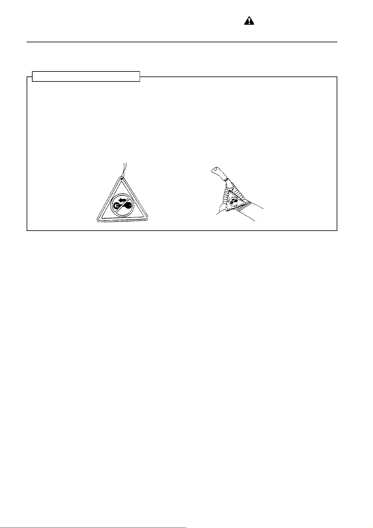
WHEN TOWING
• Injury or death could result if a disabled machine is towed incorrectly or if there is a mistake in the selection
of the wire rope, so always do as follows.
• Do not tow in a different way from the method given in the section "16.2 METHOD OF TOWING MACHINE".
• Always wear leather gloves when handling wire rope.
• When carrying out the preparation for towing with another worker, agree on signals before starting the
operation.
• If the engine on the problem machine will not start of there is a failure in the brake system, please contact
your Komatsu distributor for repairs.
• It is dangerous to tow a machine on a slope, so choose a place where there is a gradual slope. If there is no
place with a gradual slope, carry out work to make the slope as small as possible.
• If a problem machine is towed by another machine, ALWAYS use a wire rope with a suf ficient towing capacity for the weight of the problem machine.
• Do not uwe a wire rope which has cut strands 훽, kinks 훾, or reduced diameter 훿.
PC130/150LGP-6K ENG
1-21

WARNING: for reasons of
safety, always follow these
7. PRECAUTIONS DURING OPERA TION
safety precautions.
7.6 BUCKET WITH HOOK
PRECAUTIONS WHEN INST ALLING, OPERATING BUCKET WITH HOOK
Using a hydraulic excavator to raise loads is permitted under the following special conditions. These conditions
must be followed strictly .
• The specified hook must be installed to the bucket. For details, please consult your Komatsu distributor.
• When the special hook is installed, additional checks before starting and periodic checks, toghether with
recording and storing of the periodic checks are required.
• When carrying out operations with a lifted load, set the machine on firm flat ground in a safe place and install
the wire securely to the lifting hook.
• Lifting work is prohibited except for the main purpose. Never raise or lower people in this way .
• Do not allow anyonde inside the operating radius.
• When carrying out lifting work, determine the method and order of operations and signals to be used.
Appoint a leader and follow his directions.
• Wear leather gloves when handling the wire rope. Use only wire rope which fulfils the specified standards.
• Run the engine at low speed when carrying out the lifting work.
• Do not leave the operator's seat when the load is raised.
• It is dangerous to use the work equipment to pull loads in or to the side or to carry out work that exceeds the
capacity of the work equipment. Do not carry out such operations.
• Do not travel with a raised load.
• Depending on the operating posture of the work equipment, there is danger that the wire rope or ring may
slip from the hook, so always pay attention to the angle of the hook to prevent the wire or ring from coming
off.
1-22
PC130/150LGP-6K ENG

8. PRECAUTIONS FOR
MAINTENANCE
WARNING: Failure to follow
these safety precautions may
lead to a serious accident.
8.1 BEFORE CARRYING OUT MAINTENANCE
NOTIFICA TION OF F AILURE
Carrying out maintenance not described in the Komatsu operation and maintenance manual may lead to
unexpected failures.
Please contact your Komatsu distributor for repairs.
WARNING T AG
• AL W AYS attach the "DO NOT OPERATE" warning tag to the work equipment control lever in the operator's
cab to alert others that you are working on the machine. Attach additional warning tags around the machine
if necessary.
• If others start the engine, or touch or operate the work equipment controle lever while you are performing
service or maintenance, you could suffer serious injury or death.
• These tags are available from your Komatsu distributor (Part no. 20E-00-K1340)
CLEAN BEFORE INSPECTION AND MAINTENANCE
• Clean the machine before carrying out inspection and maintenance. This will ensure that dirt does not get
into the machine and will also ensure that maintenance can be carried out safely.
• If inspection and maintenance are carried out with the machine still direty , ti will be difficult to find the location
of problems, and there is also the danger that you will get dirty or mud in your eyes, and that you will slip and
injure yourself.
• When washing the machine, always do as follows.
• Wear non-slip shoes to prevent yourself from slipping on the wet surface.
• When using high-pressure steam to wash the machine, always wear protective clothing. This will protect
you from being hit by high-pressure water, and cutting your skin or getting mud or dust into your eyes.
• Do not spray water directly on to the electrical system (sensors, connectors) 햲. If water gets into the
electrical system, there is danger that it will cause defective operation and malfunction.
PC130/150LGP-6K ENG
1-23

WARNING: for reasons of
safety, always follow these
8. PRECAUTIONS FOR MAINTENANCE
safety precautions.
KEEP WORK PLACE CLEAN AND TIDY
Do not leave hammers or other tools lying around inthe work place. Wipe up all grease, oil, or other substances
that will cause you to slip. Always keep the work place clean and tidy to enable you to carry out operations
safely .
If the work place is not kept clean and tidy , there is danger that you will trip, slip or fall over and injure yourself.
APPOINT LEADER WHEN WORKING WITH OTHERS
When repairing the machine or when removing and installing the work equipment, appoint a leader and follow
his instructions during the operation.
When working with others, misunderstanding between workers can lead to serious accidents.
RADIA TOR W A TER LEVEL
• When inspecting the radiator water level, stop the engine and wait for the engine and radiator to cool down.
Check the water level in the sub-tank. Under normal conditions, do not open the radiator cap.
• If there is no sub-tank, or the radiator cap must be removed, always do as follows.
• Wait for the radiator water temperature to go down before checking the water level. (When checking if the
water temperature has gone down, put your hand near the engine or radiator and check the air temperature.
Be careful not to touch the radiator or the engine).
• Release the internal pressure before removing the radiator cap, and remove the radiator cap slowly .
STOP ENGINE BEFORE CARRYING OUT INSPECTION AND MAINTENANCE
• When carrying out inspection and maintenance, park the machine on level ground where there is no danger
of falling rocks or land slides, or of flooding if the land is low, then lower the work equipment to the ground
and stop the engine.
• Operate the right work equipment control lever several times to the RAISE and LOWER positions to release
the remaining pressure in the hydraulic circuit, then set safety lock lever 햲 to the LOCK position.
• Put blocks under the track to prevent the machine from moving.
• The worker carrying out the maintenance should be extremely careful not to touch or get caught in the
moving parts.
1-24
PC130/150LGP-6K ENG

WARNING: Failure to follow
these safety precautions may
lead to a serious accident.
8. PRECAUTIONS FOR MAINTENANCE
SAFETY DEVICES FOR WORK EQUIPMENT
When carrying out inspection and maintenance with the work equipment raised, fit stand (2) securely to the
boom to prevent the work equipment from coming down.
Place the work equipment control levers at HOLD, and set safety lock lever 햲 to the LOCK position.
PROPER TOOLS
Use only tools suited to the task. Using damaged, low quality, faulty or makeshift tools could cause personal
injury.
Broken pieces of chisels or hammers could fly into your eyes and blind you.
Tools See "21.1 INTRODUCTION OF NECESSAR Y T OOLS".
PERIODIC REPLACEMENT OF SAFETY CRITICAL PARTS
Hoses and other parts of the fuel, hydraulic and brake system are critical parts for ensuring safety, so they must
be replaced periodically .
Replacement of safety critical parts requires skill, so please ask your Komatsu distributor to carry out replacement.
• Replace these components periodically with new ones, regardless of whether or not they appear to be
defective.
These components deteriorate over time, and can cause fire because of oil leakage or failure in the work
equipment system.
• Replace or repair any such components if any defect is found, even though they have not reached the time
specified
Replacement of safety critical parts See 22. PERIODIC REPLACEMENT OF SAFETY CRITICAL
P ARTS".
PC130/150LGP-6K ENG
1-25

WARNING: for reasons of
safety, always follow these
8. PRECAUTIONS FOR MAINTENANCE
safety precautions.
USE OF LIGHTING
• When checking fuel, oil, or battery electrolyte, always use lighting with anti-explosion specifications.
If such lighting equipment is not used, there is danger of explosion.
• If work is carried out in dark places without installing lighting, there is danger of injury, so always install
proper lighting.
• Even if it is dark, do not use a lighter or flame instead of lighting. There is danger of starting a fire and if the
battery gas ignites it may cause an explosion.
• When using the machine as the power supply for the lighting, follow the instructions in this Operation and
Maintenance Manual.
PREVENTION OF FIRE
There is danger of the fuel and battery gas catching fire during maintenance, so always follow the precautions
below when carrying out maintenance.
• Store fuel, oil, grease and other flammable materials away from flame.
• Use non-flammable materials as the flushing oil for cleaning parts. Do not use diesel oil or gasoline. There is
danger that they will catch fire.
• Never smoke when carrying out inspection or maintenance. Always smoke in the prescribed place.
• When checking fuel, oil, or battery electrolyte, always use lighting with anti-explosion specifications. Never
use lighters of matches as lighting.
• When carrying out grinding or welding operations on the chassis, remove any inflammable materials to a
safe place.
• Be sure that a fire extinguisher is present at the inspection and maintenance point.
1-26
PC130/150LGP-6K ENG

WARNING: Failure to follow
these safety precautions may
lead to a serious accident.
8. PRECAUTIONS FOR MAINTENANCE
8.2 DURING MAINTENANCE
PERSONNEL
Only authorized personnel can service and repair the machine. Do not allow unauthorized personnel into the
area. If necessary employ an observer.
Extra precaution should be used when grinding, welding and using a sledge-hammer.
ATTACHMENTS
• Appoint a leader before starting removal or installation operations for attachments.
• Do not allow anyone other than the workers close to the machine or attachment.
• Place attachments that have been removed from the machine in a
safe place so that they do not fall. Put a fence around the attachments and set up No Entry signs to prevent unauthorized persons
from coming close.
WORK UNDER THE MACHINE
• Stop the machine on firm, level ground and always lower all work equipment to the ground before performing
service or repairs under the machine.
• Always block the track shoes securely .
• It is extremely dangerous to work under the machine if the track
shoes are off the ground and the machine is supported only by the
work equipment. Never work under the machine if the machine is
poorly supported.
WORK ON TOP OF THE MACHINE
• When carrying out maintenance on top of the machine, make sure that the footholds are clean and free of
obstructions, and follow the precautions below to prevent yourself from falling.
• Do not spill oil or grease.
• Do not leave tools lying around.
• Mind your step when you are walking.
• Never jump down from the machine. When getting on or off the machine, always use the steps and handrails,
and maintain three-point contact (both feet and one hand or both hands and one foot) at all times.
• Use protective equipment if necessary.
PC130/150LGP-6K ENG
1-27

WARNING: for reasons of
safety, always follow these
8. PRECAUTIONS FOR MAINTENANCE
safety precautions.
LOCKING INSPECTION COVERS
When carrying out maintenance with the inspecton cover open, lock it securely with a lock bar. If maintenance
is carried out with the inspection cover open and not locked in position, it may close suddenly if knocked or
blown by the wind, and may cause injury to the operator.
MAINTENANCE WITH THE ENGINE RUNNING
To prevent injury, do not carry out maintenance with the engine running. If maintenance must be carried out
with the engine running, carry out the operation with at least two workers and do as follows.
• One worker must always sit in the operator's seat and be ready to stop the engine at any time.
All workers must maintain contact with the other workers.
• When carrying out operations near rotating parts there is danger of being caught in the parts, so be extremely careful.
• When cleaning inside the radiator, set safety lock lever 햲 to the LOCK position to prevent the work equipment from moving.
• Do not touch any control levers. If any control lever must be operated, always give a signal to the other
workers to warn them to move to a safe place.
• Never touch the fan blade or fan belt with any tool or any part of your body . There is danger of serious injury.
DO NOT DROP TOOLS OR PARTS INSIDE MACHINE
• When opening the inspection window or tank oil filler to carry out inspection, be careful not to drop any nuts,
bolts, or tools inside the machine.
If such parts are dropped into the machine, it will cause breakage of the machine, mistaken operation and
other failures. If you drop any part into the machine, always be sure to remove it from the machine.
• When carrying out inspection, do not carry any unnecessary tools or parts in your pocket.
PRECAUTIONS WHEN USING HAMMER
When using a hammer, always wear safety glasses, safety helmet, and
other protective clothing, and put a brass bar between the hammer and
the part being hammered.
If hard metal parts such as pins, edges, teeth, or bearings are hit with a
hammer, there is danger that broken pieces might fly into your eyes and
cause injury.
1-28
PC130/150LGP-6K ENG

WARNING: Failure to follow
these safety precautions may
lead to a serious accident.
8. PRECAUTIONS FOR MAINTENANCE
REP AIR WELDING
Welding operations must always be carried out by a qualified welder and in a place equipped with a proper
equipment. Gas is generated and there is danger of fire or electrocution when carrying out welding, so never
allow any unqualified personnel to carry out welding.
The qualified welder must follow the precautions given below.
• Disconnect the battery terminals to prevent explosion of the battery.
• Remove the paint from the place being welded to prevent gas from being generated.
• If hydraulic equipment or piping, or places close to these are heated, flammable vapor of spray will be
generated and there is danger of this catching fire, so avoid applying heat to such places.
• If heat is applied directly to rubber hoses or piping under pressure, they may suddenly burst, so cover them
with fireproof sheeting.
• Always wear protective clothing.
• Ensure that there is good ventilation.
• Clear up any flammable materials, and make sure that there is a fire extinguisher at the workplace.
PRECAUTIONS WITH BA TTERY.
When repairing the electrical system or when carrying out electrical welding, remove the negative - terminal
of the battery to stop the flow of current.
Handling battery See "16.6 IF BATTERY IS DISCHARGED".
WHEN ABNORMALITY IS LOCATED
• If any abnormality is found during inspection, always carry out repairs. In particular, if the machine is used
when there is any abnormality in the brakes or work equipment systems, it may lead to serious accidents.
• Depending on the type of failure, please contact your Komatsu distributor for repairs.
RULES TO FOLLOW WHEN ADDING FUEL OR OIL
If any flame is brought close to fuel or oil, there is danger that it will catch fire, so always follow the precautions
below.
• Stop the engine when adding fuel or oil.
• Do not smoke.
• Spilled fuel and oil may cause you to slip, so always wipe it up immediately .
• Always tighten the cap of the fuel and oil fillers securely .
• Always add fuel and oil in a well-ventilated place.
PC130/150LGP-6K ENG
1-29

WARNING: for reasons of
safety, always follow these
8. PRECAUTIONS FOR MAINTENANCE
safety precautions.
PRECAUTIONS WHEN USING HIGH-PRESSURE GREASE TO
ADJUST TRACK TENSION
• Grease is pumped into the track tension adjustment system under high pressure.
If the specified procedure for maintenance is not followed when making adjustment, valve 햲 may fly out and
cause damage or personal injury.
• When loosening grease drain valve 햲 never loosen it more than one turn.
• Never put your face, hands, feet or any other part of your body directly in front of any grease drain valve.
Adjusting track tension See 24.2 WHEN REQUIRED".
HANDLING HIGH PRESSURE HOSES
• If oil or fuel leaks from high-pressure hoses, it may cause fire or defective operation, which may lead to
personal injury or damage. If any damaged hoses or loose bolts are found, stop work and contact your
Komatsu distributor for repairs.
• Replacing high-pressure hoses requires a high level of skill, and the torque is determined according to the
type of hose and size, so please do not carry out replacement yourself. Ask your Komatsu distributor to carry
out replacement.
PRECAUTIONS WITH HIGH-PRESSURE OIL
When inspecting or replacing high-pressure piping or hoses, always check that the pressure in the hydraulic
circuit has been released. If the circuit is still under pressure, it will lead to serious injury or damage, so always
do as follows.
• For details of the method of releasing the pressure - see "8.1 BEFORE CARRYING OUT MAINTENANCE,
STOP ENGINE BEFORE CARR YING OUT INSPECTION AND MAINTENANCE". Never carry out inspection or replacement before releasing the pressure completely .
• Wear safety glasses and leather gloves.
• If there is any leakage from the piping or hoses, the piping, hoses and the surrounding area will be wet, so
check for cracks in the piping and hoses and for swelling in the hoses.
If it is difficult to locate the leakage, always please contact your Komatsu distributor for repairs.
• If you are hit by a jet of high-pressure oil, consult a doctor immediately for medical attention.
1-30
INCORRECT
CORRECT
PC130/150LGP-6K ENG

WARNING: Failure to follow
these safety precautions may
lead to a serious accident.
8. PRECAUTIONS FOR MAINTENANCE
PRECAUTIONS WHEN CARRYING OUT MAINTENANCE AT HIGH TEMPERATURE
Immediately after stopping operations, the engine coolant, oil at all parts, the exhaust manifold, and the muffler
are at high temperature.
In this condition, if the cap is removed, or the oil is drained,or the filters are replaced, this may result in burns or
other injuries. Wait for the temperature to go down, then carry out the inspection and maintenance in accordance with the procedures given in this manual.
Cleaning inside of cooling system See "24.2 WHEN REQUIRED".
Checking coolant level, oil level in hydraulic tank See "24.3 CHECK BEFORE STARTING".
Checking lubricating oil level, adding oil See 24.3-7 PERIODIC MAINTENANCE".
Changing oil, replacing filters See 24.5-10 "PERIODIC MAINTENANCE".
CHECKS AFTER INSPECTION AND MAINTENANCE
Failure to carry out inspection and maintenance fully, or failure to check the functions of various maintenance
locations may cause unexpected problems and may even lead to personal injury or damage, so always do as
follows.
• Checks when engine is stopped
• Have all the inspection and maintenance locations been checked?
• Have all the inspection and maintenance items been carried out correctly?
• Have any tools or parts dropped into the machine? It is particularly dangerous if they get caught in the
lever linkage.
• Has water and oil leakage been repaired? Have bolts been tightened?
• Checks when engine is running
For details of checks when the engine is running - See 8.2 DURING MAINTENANCE, MAINTENANCE
WITH ENGINE RUNNING", and be extremely careful to ensure safety .
• Do the inspection and maintenance locations work normally?
• Is there any oil leakage when the engine speed is raised and load is applied to the hydraulic system?
WASTE MATERIALS
To prevent pollution, particularly in places where people or animals are living, always follow the procedures
given below.
• Never dump waste oil in a sewer system, rivers etc.
• Always put oil drained from your machine in containers. Never drain oil directly onto the ground.
• Obey appropriate laws and regulations when disposing of harmful objects such as oil, fuel, coolant, solvent,
filters and batteries.
INCORRECT
PC130/150LGP-6K ENG
1-31

9. POSITION FOR ATTACHING SAFETY LABELS
Always keep these labels clean. If they are lost or damaged, attach them again or replace them with a new
label.
There are other labels in addition to the safety labels listed as follows, so handle them in the same way .
Safety labels are available from your Komatsu distributor.
POSITION FOR ATTACHING SAFETY LABELS
1-32
PC130/150LGP-6K ENG

1. Warnings for operation, inspection and maintenance
1. 20E-00-K1170
9. POSITION FOR ATTACHING SAFETY LABELS
• Improper operation
and maintenance
can cause serious
injury or death
• Read the manual
and labels before
operation and
maintenance.
Follow instructions
and warnings in
manual and in labels
on machine.
• Keep the manual in
machine cab near
operator.
If this manual is lost,
please contact your
Komatsu distributor
for a replacement.
• Always apply lock
when leaving
operator's seat.
2. 20E-00-K1230
Warnings when opening front window
• When raising
window, lock it in
place with lock pins
on both sides.
• Falling window can
cause injury.
3. 20Y-00-K2220
• Emergency exit
• Read operation
manual before
operation
PC130/150LGP-6K ENG
1-33

9. POSITION FOR ATTACHING SAFETY LABELS
4. 20E-00-K1130
WARNING No passengers.
No passengers allowed
to ride on machine
while it is moving.
WARNING - DANGER
OF FALLING
OBJECTS
Do not operate where
a danger of falling
objects exists.
Consult your dealer for
fitting of FOPS protection.
HAZARDOUS Voltage hazard
Serious injury or death
can occur if machine
or attachments are not
kept safe distance away
from electric lines.
6. 20E-00-K1150
Keeping out of moving
area.
To prevent SEVERE
INJURY or DEATH do
the following before
moving machine or its
attachments:
• Sound horn to alert
people nearby.
• Be sure no one is on
or near machine or
in the swing area.
• Rotate cab for full
view of travel path if
it can be done
safely.
• Use spotter if view is
obstructed.
Always follow the
above.
5. 20E-00-K1280
Pump control override switch and swing lock override switch.
Read operation manual before operation.
7. 20E-00-K1140
1-34
PC130/150LGP-6K ENG

9. POSITION FOR ATTACHING SAFETY LABELS
8. 20E-00-K1310
• Improper operation
and maintenance
can cause serious
injury or death
• Read the manual
and labels before
operation and
maintenance.
Follow instructions
and warnings in
manual and in labels
on machine.
• Keep the manual in
machine cab near
operator.
If this manual is lost,
please contact your
Komatsu distributor
for a replacement.
10. 20E-00-K1110
• Warning for falling
from upper structure.
• Keep away from
sides of machine.
• Keep off counterweight.
• Do not ride on
machine when it is
moving.
9. 20E-00-K1190
Warning for high temperature coolant and oil
Hot water and oil
hazard
To prevent hot water
and oil from spurting
out:
• Turn engine off
• Allow water to cool.
• Slowly loosen cap to
relieve pressure
before removing.
• Read operation
manual before
operation.
PC130/150LGP-6K ENG
1-35

9.1LIFTING CAP ACITIES
One piece boom.
Arm lengths as stated. When removing bucket, linkage or cylinder lifting capacities can be increased by their
respective weights.
PC130-6K
4600
L
B
3.0m
PC130-6k
2.5m
2.1m
A
XAMm0.7m0.6m5.4m0.3m5.1
m0.60051• 0051• 0532• 0522
m5.40531• 0531• 001205610572• 0522
m0.30531• 053105020561057200220543• 0543•
m5.10541• 05210002055100620502052400330586• 0526
m0.00061• 052100910051005205910593050305970565
m5.1-05710531009105410042058100830092007705450583• 0583•
m0.3-051205810042058100830092057700550046• 0046•
m5.4-0513• 0542009300030046• 056505201• 05201•
m0.60081• 0081•
m5.40071• 0071• 008205220513• 0513•
m0.30071• 055105020561057200220593• 05530515• 0515•
m5.10081• 05410002008105620012002400330587• 0516
m0.0058105410591055105520002009300030557• 0075
m5.1-050200810052059100930003009700650044• 0044•
m0.3-0062050205830592059700750067• 0067•
m5.4-0033• 0033• 0045• 0045•
m0.60522• 0522• 0533• 0533•
m5.40502• 0002057200220053• 0053•
m0.30502• 0071007205120034• 05430095• 0095•
m5.10002055100020061006205020514052305380006
m0.00002006100520002059305030086• 0565
m5.1-052200810052059100930003009700650574• 0574•
m0.3-05920532009300030047• 05750088• 0088•
m5.4-
gk
1-36
PC130/150LGP-6K ENG

9.1 LIFTING CAPACITIES
One piece boom.
Arm lengths as stated. When removing bucket, linkage or cylinder lifting capacities can be increased by their
respective weights.
PC150LGP-6K
PC130/150LGP-6K ENG
1-37

9.1 LIFTING CAPACITIES
OVERLOAD CAUTION
This machine is equipped with an overload caution system which give a visual warning (on monitor) and an
audible warning when lifting a load close to the lift capacity of the machine. For operation of this system refer to
section 12.22
A decal inside the operator's cab shows the loads at which the caution warning is given for various work
equipment positions.
Due to the simple nature of this system the overload warning is given at a lower load than actually allowable
(see full lift capacity charts on previous page).
If lifting to the full capacity of the machine is required it is necessary to fit a full overload caution system (with
work equipment position sensing) to the machine.
Decal showing lifting loads at overload warning.
PC130-6K
1-38
A
B
m0.6m5.4m0.3
m5.40590501
m0.3051105410522
m5.1053100810503
m0.0053105810533
PC130/150LGP-6K ENG

9.1 LIFTING CAPACITIES
PC130/150LGP-6K ENG
1-39

MEMO
1-40
PC130/150LGP-6K ENG

OPERATION
PC130/150LGP-6K ENG
2-1

10.GENERAL VIEW
10.1 GENERAL VIEW OF MACHINE
If directions are indicated in this section, they refer to the directions shown by the arrows in the diagram below.
2-2
PC130/150LGP-6K ENG

10.2 GENERAL VIEW OF CONTROLS AND GAUGES
10. GENERAL VIEW
PC130/150LGP-6K ENG
2-3

11.EXPLANATION OF COMPONENTS
The following is an explanation of the devices neede for operating the
machine.
To carry out suitable operations correctly and safely, it is important to
understand fully the methods of operating the equipment and the meaning of the displays.
11.1 MACHINE MONITOR
A. BASIC CHECK ITEMS (11.1.1)
This displays the basic items that should be checked before starting
the engine.
If there is any abnormality, the appropriate monitor lamp will flash.
NOTICE
When carrying out checks before starting, do not simply rely on
the monitor. Always refer to the periodic maintenance items or "12.
OPERATION" to carry out the checks.
2-4
PC130/150LGP-6K ENG

B. CAUTION ITEMS (11.1.2)
CAUTION
If these monitor items flash, check and repair the appropriate
location as soon as possible.
These are items which need to be observed while the engine is running. If any abnormality occurs, items which need to be repaired as soon
as possible are displayed.
If there is any abnormality, the appropriate monitor lamp will flash to
indicate the location of the abnormality.
C. EMERGENCY STOP ITEMS (11.1.3)
CAUTION
If these monitor items flash stop operations immediately, then
check and repair the appropriate location.
These are items which need to be observed while the engine is running. If any abnormality occurs, items which need to be repaired immediately are displayed.
Ifthere is any abnormality, the appropriate monitor lamp will flash to
indicate the location of the abnormality and the buzzer will sound.
1 1. EXPLANATION OF COMPONENTS
D. METER DISPLAY PORTION (11.1.4)
This portion consists of pre-heating monitor, swing lock monitor, engine water temperature gauge, fuel gauge and display.
E. SWITCHES (11.1.5)
The switches are used for setting clock time and for selecting working
mode, active mode and travel speed.
PC130/150LGP-6K ENG
2-5

1 1. EXPLANATION OF COMPONENTS
11.1.1 A: BASIC CHECK ITEMS
NOTICE
Do not rely on the "BASIC CHECK ITEMS" only for the check
before starting.
Always refer to the periodic maintenance items or "12. OPERA-
TION" to carry out the checks.
1. RADIA TOR W A TER LEVEL
This warns that the radiator cooling water level is too low.
If the monitor lamp flashes, check the cooling water level in the radia-
tor and reserve tank and add water.
2. ENGINE OIL LEVEL
This warns that the oil level in the engine oil pan is too low.
If the monitor lamp flashes, check the oil level in the engine oil pan,
and add oil.
2-6
PC130/150LGP-6K ENG

3. REPLACEMENT OF ENGINE OIL (or only set machines)
If the set time (125, 250, 500H) passes after the engine oil is re-
placed, this lamp lights up. At this time, replace the engine oil.
11.1.2 B: CAUTION ITEMS
CAUTION
If the caution monitor lamp flashes, repair the problem as soon
as possible.
1. CHARGE LEVEL
This monitor indicates an abnormality in the charging system while
the engine is running.
If the monitor lamp flashes, check the V-belt tension. If any abnor-
mality is found, see "16.7 OTHER TROUBLE"
1 1. EXPLANATION OF COMPONENTS
REMARK
While the starting switch is ON, the lamp will remain lit and will go off
once the engine is started.
2. FUEL LEVEL
If the fuel drops below 25 liters the lamp will flash. Top up the fuel
before this.
3. AIR CLEANER CLOGGING
This warns that the air cleaner is clogged.
If the monitor lamp flashes, stop the engine then inspect and clean
the air cleaner.
PC130/150LGP-6K ENG
2-7

1 1. EXPLANATION OF COMPONENTS
4. OVERLOAD CAUTION (When lifting)
This warns that the machine is close to tipping due to the load (an
audible warning is also given), if the warning is given lower the load. Refer
to the lifting capacity chart for safe load.
This function is operated by an additional switch positioned in the tool
case. Refer to section 12.22.
11.1.3 C: EMERGENCY STOP ITEMS
CAUTION
If any monitor lamp flashes, stop the engine or run it at low idling
and take the following action.
1. ENGINE WA TER TEMPERA TURE
If the temperature of the engine cooling water becomes abnormally
high, the monitor lamp flashes and the overheat prevention system is automatically actuated to reduce the engine speed.
Stop operations and run the engine at low idling until the engine water temperature gauge enters the green range.
2. RADIA TOR W A TER LEVEL
If the radiator water level drops, the monitor lamp flashes. Stop the
engine, check the radiator water level and add water if necessary .
3. ENGINE OIL PRESSURE
If the engine oil pressure drops below the normal pressure, the monitor lamp flashes. At this item, stop the engine and inspect it according to
"16.7 OTHER TROUBLE".
REMARK
While the starting switch is ON, the lamp remains lit and goes off
once the engine is started. When the engine starts the buzzer may sound
for a short time, however, this does not indicate a fault.
2-8
PC130/150LGP-6K ENG

1 1. EXPLANATION OF COMPONENTS
11.1.4 D: METER DISPLA Y PORTION
PILOT DISPLA Y
When the starting switch is ON, the pilot display lights up when the
display items are functioning.
1. ENGINE PRE-HEA TING MONIT OR
This monitor lamp indicates the pre-heating time required when
starting the engine at an ambient temperature below 0°C.
The monitor lamp lights when the starting switch is turned to HEAT
position and flashes after about 30 seconds to show that the pre-heating
is completed. (The monitor lamp will go off after about 10 seconds).
2. SWING LOCK MONITOR
This informs the operator that the swing lock is being actuated.
Actuated: Lights up
When the swing lock switch is turned ON (ACTUATED), the monitor
lamp lights up.
When the swing lock override switch is turned on, this monitor lamp
flashes.
REMARK
A disc brake is installed in the swing motor to mechanically stop motor rotation.
The brake is always applied while the swing lock is actuated.
PC130/150LGP-6K ENG
2-9

1 1. EXPLANATION OF COMPONENTS
METERS
3. ENGINE WA TER TEMPERATURE GAUGE
This gauge indicates the engine cooling water temperature.
If the temperature is normal during operation, the green range will
light up.
If the red range lights up during operation, the overheat prevention
system will be actuated.
The overheat prevention system acts as follows.
Red range lights up:
Engine water temperature monitor flashes
Red range lights up:
Engine speed is lowered further to low idling, engine water temperature monitor flashes and alarm buzzer sounds at the same time.
The overheat prevention system is actuated until the temperature
enters the green range.
When red range lights, if the engine water temperature is reduced
andthe fuel control dial is turned to the low idling position, the display wil
be cancelled.
4. FUEL GAUGE
This gauge indicates the amount of fuel in the fuel tank.
If the fuel level is normal during operation, the green range will light
up.
If only the red range lights up during operation there is less than 25
liters of fuel remaining in the tank so check and add fuel.
After the starting switch is turned ON, the correct level may not be
displayed for a moment, but this does not indicate any abnormality.
When stopping the engine turn the starting switch ON and check that
the monitor lamps on items A, B, C and D and the meters light up.
5. DISPLAY
This normally displays the clock time. If any error occurs, it indicates
error information while the starting switch is ON.
2-10
PC130/150LGP-6K ENG

Manual setting
1. When the time is displayed depress clock switch for 2.5 sec or
more.
2. " " flashes.
3. Pressing H switch increases hours and pressing M switch in-
creases minutes. If switch or is pressed for 2.5 seconds or
more, hours or minutes increase continuously.
4. When the correct time is reached, press clock switch . This completes clock setting.
Correct time setting
1. When the time is displayed, depress the clock switch for 2.5 sec or
more.
2. " " flashes.
3. When SET switch is pressed, the hour is rounded off for 0 to 14
minutes and rounded up for 45 to 59 minutes.
(Examples) 10:14 becomes 10:00 (rounded off)
10:45 becomes 11:00 (rounded up)
When SET switch is pressed at the time signal or standard clock,
the correct time is obtained.
4. When the correct time is reached, press clock switch . This completes clock setting.
11. EXPLANATION OF COMPONENTS
If the machine has a fault, error information appears while the start-
ing switch is ON. The monitor flashes and displays all error informations
sequentially.
Monitor indications Error mode
E02 TVC valve system error
E03 Swing brake system error
E05 Governor system error
CALL Non-operating error
If any of these monitors flash, see "16.7.4 ELECTRONIC CONTROL
SYSTEM".
6. SERVICE METER
This meter shows the total operation hours of the machine.
Set the periodic maintenance intervals using this display.
The service meter advances while the engine is running - even if the
machine is not travelling.
The meter will advance by 1 for each hour of operation regardless of
the engine speed.
PC130/150LGP-6K ENG
2-11

1 1. EXPLANATION OF COMPONENTS
11.1.5 E: SWITCHES
1. WORKING MODE SELECTOR SWITCH (Basic switch)
This switch is used to set the movement of power for the work
euipment. By selecting the mode to match the working conditions, it is
possible to carry out operations more easily.
H.O. (heavy-duty operation mode) lights up:
This is used for heavy-duty work.
G.O. (general operation mode)lights up:
This is used for ordinary work.
F.O. (finishing operation mode) lights up:
This is used for levelling or grading work.
L.O. (lifting operation mode) lights up:
This is used for fine control operations.
B.O. (breaker operation mode) lights up:
This is used for breaker work.
When starting the engine, G.O. (general operation) mode is automatically selected. Each time the switch is pressed, the mode selection
changes.
NOTICE
When the breaker is used, never select the H.O. (heavy-duty operation) mode.
REMARK
H switch is also used for setting "hours" in the clock and M switch for
setting "minutes". See 11.1.4-5 DISPLAY.
2-12
PC130/150LGP-6K ENG

2. AUTO-DECELERA TION SWITCH (Selection switch)
This switch acts to activate the function that automatically lowers the
engine speed and reduces fuel consumption when the control lever is at
neutral.
ON lights up: Auto-deceleration is actuated
Off: Auto-deceleration is cancelled
Each time the switch is pressed, the auto-deceleration is actuated or
cancelled.
3. TRAVEL SPEED SWITCH
1 1. EXPLANATION OF COMPONENTS
WARNING
If the Hi-Lo switch is operated when the machine is travelling,
the machine may deviate even when travelling in a straight line.
To prevent this, always stop the machine before operating the
travel speed switch.
This is used to select the three travel speeds.
Lo lights up: Low speed travel
Mi lights up: Mid range speed travel
Hi lights up: High speed travel
When the engine is started, the travel speed is automatically st to Lo.
When travelling in Hi, the travel speed is automatically switched to middle
speed travel (Mi) to match the travel surface on soft ground or when travelling uphill, so there is no need to operate this switch.
The monitor indication keeps lamp Hi lighted.
PC130/150LGP-6K ENG
2-13

1 1. EXPLANATION OF COMPONENTS
4. POWER MAX./SWIFT SLOW-DOWN SWITCH
During operations, the digging power can be increased and the
speed reduced by a one-touch operation of the knob button (single click
while pushing).
Power max. (power up) lights up:
When the working mode is heavy-duty and general operation modeonly,
the power can be increased approx. 30% (genral operation mode) and the
set pressure can be increased approx. 9% (heavy-duty operation mode
and general operatonmode) while the knob button is being pressed. Even
if the knob button continues to be pressed, the increase in power finishes
after approx. 8.5 sec.
Swift slow-down (speed down) lights up:
When the working mode is heavy-duty operation and general operation
mode only, the speed is reduced approx. 35% for heavy-duty operation
mode and approx. 25% for general operation mode, and the set pressure
is increased approx. 9% for heavy-duty operation mode and general operation mode.
When the engine is strated, the power max. lamp lights up. Each time the
set switch is pressed, the mode is switched.
5. ACTIVE MODE SWITCH (SELECTOR SWITCH)
The active mode is effective for quick levelling operations of deep
digging and loading operations.
ON lights up: Active mode ON
ON goes out: Active mode cancelled
The ON lamp is off when the engine is started.
If it is turned ON (lights up), ti is possible to enter the active mode
from any working mode.
Even when it is turned ON (lights up), the working mode display does
not change. When the lamp goes out, the system returns to the original
working mode.
NOTICE
When using the breaker, do not set to the active mode.
2-14
PC130/150LGP-6K ENG

11.2 SWITCHES
1 1. EXPLANATION OF COMPONENTS
1. ST ARTING SWITCH
This switch is used to start or stop the engine.
OFF position
The key can be inserted or withdrawn. Except for the cab lamp, radio
(if fitted) and clock, the switches for the electric system are all turned off
and the engine is stopped.
ON position
Electric current flows in the charging and lamp circuits.
Keep the starting switch key at the ON position while the engine is
running.
START position
This is the engine-start position. Keep the key at this position during
cranking. Immediately after starting the engine, release the key which will
automatically return to the ON position.
HEA T (preheat) position
When starting the engine in winter, set the key to this position. When
the key is set to the HEAT position, the pre-heating monitor lights up. Keep
the key at this position until the monitor lamp goes off. Immediately after
the pre-heating monitor goes off, release the key. The key automatically
returns to the OFF position. Then, start the engine by turning the key to
the ST AR T position.
PC130/150LGP-6K ENG
2-15

1 1. EXPLANATION OF COMPONENTS
2. FUEL CONTROL DIAL
(WITH AUTO-DECELERA TION MECHANISM)
This adjusts the engine speed and output.
Low idling (MIN): Turned fully to the left
Full speed (MAX): Turned fully to the right
3. CIGARETTE LIGHTER
This is used to light cigarettes. To use, push the lighter in. After a few
seconds it will spring back.
Pull out the lighter and light your cigarett.
Nothing may be connected to the cigarette lighter without the prior
persmission of an authorised Komatsu distributor.
4. SWING LOCK SWITCH
WARNING
• When the machine is travelling under its own power, or when
the swing is not being operated, always set the switch to the
ON (ACTUA TED) position.
• On a slope, the work equipment may swing to the down side
even if the swing lock switch is located at the ON position. Be
careful concerning this point.
This switch is used to lock the upper structure so that it cannot swing.
ON position (actuated):
The swing lock is always applied, and the upper structure will not
swing even if the swing is operated. In this condition, the swing lock lamp
lights up.
OFF position (cancelled):
The swing lock is applied only when the swing control lever is at neu-
tral; when the swing control lever is operated it is cancelled.
The swing lock is actuated approx. 4 seconds after the swing lever is
placed in neutral.
5. WIPER SWITCH
This switch actuates the front window wiper.
OFF: the wiper stops
ON: the wiper moves continuously
Window washer fluid is sprayed out: when the switch is released, it
returns to .
ON: the wiper moves intermittently .
Window washer fluid is sprayed out: when the switch is released, it
returns to .
2-16
PC130/150LGP-6K ENG

6. LAMP SWITCH
This switch turns on the working lamps and monitor illumination
OFF
Standard work lamps
Standard and additional work lamps (if fitted)
7. ALARM BUZZER STOP SWITCH
This is used to stop the alarm buzzer when it has sounded to warn of
some abnormality in the EMERGENCY STOP ITEMS while the engine is
running.
8. CAR HEA TER FAN SWITCH
This adjusts air-flow in 2 steps.
Hi: strong
Lo: weak
OFF: car heater turned off.
1 1. EXPLANATION OF COMPONENTS
9. HORN BUTTON
When the button at the tip of the right work equipment control lever is
pressed, the horn will sound.
10. KNOB BUTTON
The button at the tip of the left work equipment control lever is used
to actuate the power max./swift slow-down functions. Press the button
once (single click) and keep it depressed. In the heavy-duty and general
operation modes the power max. function actuates for max. 8.5 seconds
and the swift slow-down function actuates while the button is depressed.
11. HEATED OPERA TION SEAT SWITCH (if fitted)
This switch is used to switch on the heated seat.
OFF: seat not heated
ON: seat heated
PC130/150LGP-6K ENG
2-17

1 1. EXPLANATION OF COMPONENTS
12. ADDITIONAL LAMP SWITCH
This switch is provided to turn on an additional lamp on the cab front
top. Setting to OFF turns the switch off.
13. CAB LAMP SWITCH
This lights up the cab lamp.
ON position: lights up.
The cab lamp can be turned on even when the starting switch is at
the OFF position, so be careful not to leave it on by mistake.
14. PUMP CONTROL OVERRIDE SWITCH
When normal: Switch is down
When abnormal: When the monitor display shows E02 (TVC valve
system error), it is possible to carry out operation when this switch is
moved up. The pump control override switch is designed to allow operations to be carried out for a short period when there is an abnormality in
the pump control system (TVC valve system error). The abnormality must
be repaired immediately.
15. SWING LOCK OVERRIDE SWITCH
When normal: switch is down
When abnormal: when the monitor display shows E03 (swing brake
system error), the brake is cancelled and it becomes possible to swing the
upper structure when this switch is moved up, so normal operations can
be carried out. However, the swing brake remains cancelled.
The swing lock override switch is designed to allow operations to be
carried out for a short period when there is an abnormality in the swing
brake electrical system (swing brake system error). The abnormality must
be repaired immediately.
2-18
PC130/150LGP-6K ENG

11.3 CONTROL LEVERS, PEDALS
1 1. EXPLANATION OF COMPONENTS
1. SAFETY LOCK LEVER
WARNING
• When leaving the operator's compartment, set the safety lock
lever securely to the LOCK position. If the control levers are
not locked, and they are touched by mistake, this may lead to a
serious accident.
If the safety lock lever is not placed securely in the LOCK position, the control levers may not be properly locked. Check that
the situation is as shown in the diagram.
• When the safety lock lever is raised, take care not to touch the
work equipment control lever. If the safety lock lever is not
properly locked at the upper position, the work equipment and
swing will move, creating a potentially dangerous situation.
• When the safety lock lever is lowered, take care not to touch
the work equipment control lever.
This lever locks the work equipment, swing, travel and attachment
controls.
This lock lever is a hydraulic lock, so even if it is in the lock position,
the work equipment control lever and travel lever will move, but the work
equipment, travel motor and swing motor will not work.
PC130/150LGP-6K ENG
2-19

1 1. EXPLANATION OF COMPONENTS
2. TRA VEL LEVERS (WITH PEDAL, AUTO DECELERATION
MECHANISM)
WARNING
• Do not put your foot on the pedal unless the machine is travelling. If you leave your foot on the pedal and press it by mistake, the machine will move suddenly, and this may lead to a
serious accident.
• With the track frame facing to the rear, the machine will move
in the reverse direction by forward travelling and in the forward direction by reverse travelling.
When the travel lever is used, check to see if the track frame is
facing forward or backward. (If the sprocket is located to the
rear, the track frame is facing forward).
FORWARD:
The lever is pushed forward
(the pedal is angled forward)
REVERSE:
The lever is pulled back
(The pedal is angled back)
N (Neutral): The machine stops
( ): This indicates operation of the pedal.
2-20
PC130/150LGP-6K ENG

3. LEFT WORK EQUIPMENT CONTROL LEVER
(with auto deceleration device)
WARNING
If any lever is operated when in the deceleration range, the engine speed will suddenly increase, so be careful when operating
the levers.
This lever is used to operate the arm and upper structure.
Arm operation Swing operation
Arm OUT Swing to the right
Arm IN Swing to the left
N (Neutral)
When the lever is in this position, the upper structure and the arm will
be retained in the position in which they stop.
4. RIGHT WORK EQUIPMENT CONTROL LEVER
(with auto-deceleration device)
1 1. EXPLANATION OF COMPONENTS
WARNING
If any lever is operated when in the deceleration range, the engine speed will suddenly increase, so be careful when operating
the levers.
This lever is used to operate the boom and bucket
Boom operation Bucket operation
RAISE DUMP
LOWER CURL
N (Neutral)
When the lever is in this position, the boom and the bucket will be
retained in the position in which they stop.
For levers 2, 3 and 4 the engine speed changes as follows because
of the auto-deceleration mechanism.
• When the travel lever and work equipment control levers are at neutral, even if the fuel control dial is above the mid-range postion, the
engine speed will drop to a mid-range speed.
If any of the levers are operated, the engine speed will rise to the
speed set by the fuel control dial.
• If all control levers are set to neutral, the engine speed will drop by
approx. 100 rpm, and after approx 4 seconds, the engine speed will
drop to the deceleration speed (approx. 1400 rpm).
PC130/150LGP-6K ENG
2-21

1 1. EXPLANATION OF COMPONENTS
5. A TT ACHMENT CONTROL PEDAL
WARNING
Do not put your foot on the pedal except when operating the
pedal. If resting your foot on the pedal during operation and it is
depressed by accident the attachment may move suddenly and
cause serious damage or injury.
When breaker is installed
• When the front part of the pedal is depressed, the breaker is actu-
ated.
• Screw lock pin into hol in pedal to lock (Pedal is disabled. Unscrew
completely to unlock).
• Set the working mode to the breaker (B.O.) and unlock pedal.
When general attachment is installed:
• When the pedal is depressed, the attachment is actuated.
• Unlock the pedal to operate
When no attachment is fitted or when attachment operation is not
required:
• Lock pedal using lock pin.
2-22
PC130/150LGP-6K ENG

HYDRAULIC OIL FLOW
When the front of the pedal is depressed, the oil flows to the left
piping for the work equipment; when the rear of the pedal is depressed
the oil flows to the right piping for the work equipment. (When the breaker
is installed, only the front pedal is used).
6. BREAKER, GENERAL ATTACHMENT (CRUSHER ETC.) SELEC-
TOR V AL VE
1 1. EXPLANATION OF COMPONENTS
SELECTOR V AL VE
This switches the flow of the hydraulic oil.
Position : When breaker is used
Position : When general attachment is used (crusher etc.)
PC130/150LGP-6K ENG
2-23

1 1. EXPLANATION OF COMPONENTS
11.4 CEILING WINDOW
WARNING
When leaving the operator's compartment, set the safety lock
lever securely to the LOCK position.
If the control levers are not locked and they are touched by mistake, this may lead to a serious accident.
When opening
1. Lock the safety lock lever securely .
2. Check for any ceiling window movement by pulling lock located on
both sides, then push up and open the ceiling window grasping grip
When closing
Close the ceiling window grasping grip and lock it with lock . If
the lock cannot be applied, open and close the ceiling window again.
2-24
PC130/150LGP-6K ENG

11.5 FRONT WINDOW
WARNING
When opening the front window, always hold grip firmly with
both hands and pull up. If you use only one hand, your hand may
slip and get caught.
It is possible to store (pull up) the front window (top) in the roof of the
operator's compartment.
When opening
1 1. EXPLANATION OF COMPONENTS
WARNING
When the front window is open, there is danger that it will fall, so
always lock it with left and right lock pins .
1. Place the work equipment on flat ground and stop the engine.
2. Securely lock the safety lock lever
3. Confirm that the wiper is stored inside the right frame.
4. Pull lock pins at the top left and right sides of the front window to
the inside to release the lock
PC130/150LGP-6K ENG
2-25

1 1. EXPLANATION OF COMPONENTS
5. From the inside of the operator's cab, hold the bottom grip with the
left hand and the top grip with the right hand, pull up the window, and
push it in fully until it is locked by catch
6. Lock with lock pins on the left and right sides.
When closing
WARNING
When closing the window, lower it slowly and be careful not to
get your hand caught.
1. Place the work equipment on a flat ground and stop the engine.
2. Securely lock the safety lock lever.
3. Release the lock pin
4 Hold the grip at the bottom of the front window with your left hand and
the grip at the top with your right hand, release the lock of catch
with your right thumb, then pull the top grip slowly and lower the front
window. When releasing the lock of catch , push release lever in
the direction of the arrow to release the lock.
2-26
PC130/150LGP-6K ENG

5. Lock securely with lock pins at the left and right sides.
Removing front window (bottom)
With the front window open, remove lock pins and the bottom part
of the front window can be removed.
Store the removed bottom part of the front window at the rear of the
operator's cab and lock with lock pins .
1 1. EXPLANATION OF COMPONENTS
11.6 DOOR LOCK
Use the door lock to fix the door in position after opening it.
1. The door will become fixed in place when it is pressed against catch
2. To release the lock press knob down at the left side of the opera-
tor's seat to release the catch.
When fixing the door, fix it firmly to the catch.
PC130/150LGP-6K ENG
2-27

1 1. EXPLANATION OF COMPONENTS
11.7 CAP, COVER WITH LOCK
The fuel filler, operator's cab, engine hood, battery box cover, right
side door and left side door of the machine body are fitted with locks.
Use the starting switch key to lock or unlock these places.
11.7.1 METHOD OF OPENING AND CLOSING CAP
WITH LOCK
To open the cap
1. Insert the key ibnto the cap.
2. Turn the key clockwise, align the match mark on the cap with the rotor
groove, then remove the cap.
T o lock the cap
1. Turn the cap into place.
2. Turn the key and take the key out.
Insert the key as far as it will go. If the key is turned before it is in-
serted all the way it may break.
11.7.2 METHOD OF OPENING AND CLOSING COVER
WITH LOCK (cover with lock)
T o open the cover (locked cover)
1. Insert the key .
2. Turn it counterclockwise and open the cover by pulling the cover grip.
T o lock the cover
1. Close the cover and insert the key .
2. Turn the key clockwise and take the key out.
2-28
PC130/150LGP-6K ENG

11.8 LUGGAGE TRA Y
This tray is located to the rear of the operator's seat. Always keep the
operation & maintenance manual in this box for easy reading access.
11.9 ASHTRAY
This is on the side of the operator's seat. Always make sure that you
extinguish the cigarette before closing the lid.
1 1. EXPLANATION OF COMPONENTS
PC130/150LGP-6K ENG
2-29

1 1. EXPLANATION OF COMPONENTS
11.10 CAB HEATER
11.10.1 VIEW OF CONTROLS
The car heater utilizes the water heated by the engine. Use the car
heater when the engine coolant is warmed.
1. CAR HEA TER FAN SWITCH
This adjusts air-flow in 2 steps.
Hi: strong
Lo: Weak
OFF: car heater turned off
2. AIR OUTLET CHANGE-OVER LEVER
The air outlet is selectable according to the purpose.
To upper portion of operator To upper and foot portions of
operator
Lever position
To foot portion of operatorPurpose
2-30
Air outlet
PC130/150LGP-6K ENG

3. DEFROSTER CHANGE-OVER LEVER
This lever is used to eliminate condensation produced in winter or
the rainy season etc.
Change-over lever forward: defroster
Change-over lever backward: to operator's feet
Defroster is available when using the air outlet change-over lever in
or
11.10.2 PREPARING CAR HEATER
If the ambient temperature drops, use the cab heater.
When using the cab heater, turn valve on the water pump
counterclockwise to open it.
When leaving the cab heater unused for a long time, turn valve
clockwise to close it.
1 1. EXPLANATION OF COMPONENTS
REMARK
On machines equipped with the air conditioner system always open
valve .
PC130/150LGP-6K ENG
2-31

1 1. EXPLANATION OF COMPONENTS
11.11 CAB RADIO (OPTION)
Refer to the separate operation manual for radio cassette.
Note
Ensure radio is switched off when leaving the machine for long peri-
ods to prevent draining of battery charge.
Antenna
If the reception is weak or generates noise, extend the antenna. If the
reception is too strong, adjust the sensitivity by retracting the antenna.
NOTICE
When transporting the machine or parking it in a garage, always fully
retract the antenna to avoid the possibility of breakage.
11.11.1 PRECAUTION OF USE
• To ensure safe operation, adjust the volume level so that external
noise is still audible.
• Ensure no water is splashed over the speaker case or cab radio to
prevent malfunction.
• Never use solution such as benzine or thinners to clean the dial or
buttons. These should be wiped with a dry, soft cloth. (Use a cloth
dipping in alcohol for very dirty surfaces).
• At battery replacement, all the memory pre-set with the pre-set buttons will be cleared. Perform pre-setting again.
2-32
PC130/150LGP-6K ENG

11.12 FUSE
NOTICE
Before replacing a fuse, be sure to turn off the starting switch.
The fuses protect the electrical equipment and wiring from burning
out.
If the fuse becomes corroded, or white powder can be seen, or the
fuse is loose in the fuse holder, replace the fuse.
Replace a fuse with another of the same capacity.
Fuse capacity and name of circuit
1 1. EXPLANATION OF COMPONENTS
oN
esuF
yticapac
tiucricfoemaN
A01evlavdioneloS,rellortnocpmuP
A01rellortnocronrevogenignE
A02)rotom(renoitidnocriA
A01pmalgnikrow,pmaldaehthgiR
A01
,lenaprenoitidnocriA,rethgiletteragiC,oidaR
nottubbonktfeL,rehsawwodniW,retaeH
A01nroH
A51rellortnocrepiW
A51pmalgnikrowraeR,pmaldaeH
A01A01langishctiwsyeK
A01erapS
A01erapS
A01rotinoM,rezzubmralA
A01langistratS,retaehnobbiR,yaleryrettaB
A01)pukcab(oidaR,pmalbaC
A01esuferapS
A01esuferapS
A51esuferapS
A02esuferapS
PC130/150LGP-6K ENG
2-33

1 1. EXPLANATION OF COMPONENTS
11.13 FUSIBLE LINK
If the starting motor will not rotate when the starting switch is turned
ON, a possible cause is disconnection of wire-type fusible link (1). Open
the battery room door on the left side of the machine body to inspect the
fusible link and, if necessary, replace it
REMARK
A fusible link refers to the large-sized fuse wiring installed in the high
current flow portion of the circuit to protect electrical components and
wiring from burning, similarly to an ordinary fuse.
11.14 CONTROLLERS
Governor pump controller is provided
NOTICE
• Never splash or spill water, mud or drink over the controllers as
this may cause a fault.
• If a fault occurs in the controller, do not attempt repair but con-
sult your Komatsu distributor.
11.15 TOOL BOX
This is used for keeping the tools.
11.16 GREASE PUMP HOLDER
This is inside the battery room door on the left side of the machine.
Fit the grease pump to the holder when it is not being used.
2-34
PC130/150LGP-6K ENG

11.17 REFUELLING PUMP (Option)
WARNING
Do not bring fire or sparks near the fuel
1. When the machine is operated on sites with no fuel container and
pump, the machine may be refuelled using the refuelling pump (if
fitted) from fuel barrels.
The refuelling pump is located in the tool box at the front right hand
side of the machine.
2. Place the fuel hose which is stored in tray into the fuel barrel
placed next to the machine.
3. Switch on refuelling pump using switch on the pump assembly
when adding fuel, never let the fuel overflow. This may cause fires.
NOTES
• This pump is protected by fuse . If pump fails to function check fuse
(10 A).
• Ensure strainer on hose end is clean.
1 1. EXPLANATION OF COMPONENTS
PC130/150LGP-6K ENG
2-35

12.OPERATION
12.1 CHECK BEFORE STARTING ENGINE
12.1.1 WALK-AROUND CHECK
WARNING
Leakage of oil or fuel, or accumulation of flammable material
around high temperature parts, such as the engine muffler may
cause fire.
Check carefully, and if any abnormality is found, repair it or contact your Komatsu distributor.
Before starting the engine, look around the machine and under the
machine to check for loose nuts or bolts or leakage of oil, fuel or coolant,
and check the condition of the work equipment and hydraulic system.
Check also for loose wiring, play, and collection of dust at places which
reach high temperatures.
Always carry out the items in this section before starting the engine
each day.
1. Check for damage, wear, play in work equipment, cylinders, link-
age, hoses.
Check that there are no cracks, excessive wear, or play in the work
equipment, cylinders, linkage, or hoses. If any abnormality is found,
repair it.
2-36
PC130/150LGP-6K ENG

2. Remove dirt and dust from around engine, battery radiator
Check if there is any dirt or dust accumulated around the engine or
radiator. Check also is there is any flammable material (dead leaves,
twigs, grass etc.) accumulated around the battery or high temperature engine parts, such as the engine muffler or turbocharger. Remove all such dirt or flammable material.
3. Check for leakage of water or oil around engine
Check that there is no leakage of oil from the engine or leakage of
water from the cooling system. If any abnormality is found, repair it.
4. Check for oil leakage from hydraulic equipment, hydraulic tank,
hoses, joints
Check that there is no oil leakage. If any abnormality is found, repair
the place where the oil is leaking.
5. Check the undercarriage (track, sprocket, idler, guard) for damage, wear, loose bolts, or leakage from oil from rollers
6. Check for damage to handrail, loose bolts
Repair any damage and tighten any loose.
12.OPERA TION
7. Check for damage to gauges, monitor, loose bolts
Check that there is no damage to the gauges an monitor in the operator's cab. If any abnormality is found, replace the parts. Clean off
any dirt on the surface.
8. Clean rear view mirror, check for damage
Check that there is no damage to the rear view mirror. If it is damaged, replace it with a new mirror. Clean the surface of the mirror and
adjust the angle so that the view to the rear can be seen from the
operator's seat.
9. Seat belt and mounting clamps
Check that there is no abnormality in the seat belt or mounting
clamps. If there is any damage, replace with new parts.
10. Check bucket with hook for damage
Check the hook, catcher and hook foot for damage. If damage is
found, contact your Komatsu distributor for repair.
PC130/150LGP-6K ENG
2-37

12.OPERA TION
12.1.2 CHECK BEFORE STARTING
Always carry out the items in this section before starting the engine
each day.
CHECK COOLANT LEVEL, ADD W ATER
WARNING
Do not open the radiator cap unless necessary. When checking
the coolant, always check the radiator reserve tank when the engine is cold.
1. Open the battery room door on the left side of the machine and check
that the cooling water level is between the FULL and LOW marks on
radiator reserve tank (shown in the diagram on the right). If the
water level is low, add water through the water filler of reserve tank
to the FULL level.
2. After adding water, tighten the cap securely.
3. If the reserve tank becomes empty, first inspect for water leaks and
then fill the radiator and the reserve tank with water.
CHECK OIL LEVEL IN ENGINE OIL PAN, ADD OIL
1. Open the engine hood
2. Remove dipstick and wipe the oil off with a cloth
3. Insert dipstick fully in the oil filler pipe, then take it out again.
4. The oil level should be between the H and L marks on dipstick .
If the oil level is below L mark, add engine oil through oil filler .
NOTICE
For details of the oil to use, see "20. USE OF FUEL, COOLANT
AND LUBRICANTS ACCORDING TO AMBIENT TEMPERATURE".
2-38
PC130/150LGP-6K ENG

5. If the oil is above the H mark, drain the excess engine oil from drain
valve , and check the oil level again.
6. If the oil level is correct, tighten the oil filler cap securely and close
the engine hood.
REMARK
When checking the oil level after the engine has been operated, wait
for at least 15 minutes after stopping the engine before checking.
If the machine is at an angle, make it horizontal before checking.
CHECK FUEL LEVEL ADD FUEL
12.OPERA TION
WARNING
When adding fuel, never let the fuel overflow. This may cause a
fire. If spilling fuel, thoroughly clean up any spillage.
1. Open the pump room door on the right side of the machine and use
sight gauge on the rear face of the fuel tank to check that the tank
is full.
2. If the fuel level is not within the sight gauge, add fuel through filler
port while watching sight gauge .
Fuel capacity 240 liters
NOTICE
For details of the fuel to use, see "20. USE OF FUEL, COOLANT
AND LUBRICANTS ACCORDING TO AMBIENT TEMPERATURE".
3. After adding fuel, tighten the cap securely.
REMARK
If breather hole (1) on the cap is clogged, the pressure in the dank
will drop and fuel will not flow.
Clean the hole from time to time.
PC130/150LGP-6K ENG
2-39

12.OPERA TION
CHECK OIL LEVEL IN HYDRAULIC TANK, ADD OIL
WARNING
• When removing the oil filler cap, oil may spurt out, so turn the
cap slowly to release the internal pressure before removing
the cap.
• If oil has been added to above the H mark, stop the engine and
wait for the hydraulic oil to cool down, then drain the excess
oil from the drain plug .
1. If the work equipment is not in the condition shown in the diagram on
the right, start the engine, run the engine at low speed, retract the
arm and bucket cylinders, then lower the boom, set the bucket teeth
in contact with the ground and stop the engine.
2. Open the pump room door on the right side of the machien. Check
sight gauge . The oil level is normal if between the H and L marks.
NOTICE
Do not add oil if the level is above the H line. This will damage
the hydraulic equipment and cause the oil to spurt out.
3. If the level is below the L mark, remove the upper cover of the hydraulic tank and add oil through oil filler .
NOTICE
For details of the oil to use, see "20. USE OF FUEL, COOLANT
AND LUBRICANTS ACCORDING TO AMBIENT TEMPERATURE".
REMARK
The oil level will vary depending upon the oil temperature. Accord-
ingly, use the following as a guide:
• Before operation: around L level
(Oil temperature 10 to 30°C)
• Normal operation: around H level
(Oil temperature 50 to 80°C)
2-40
PC130/150LGP-6K ENG

CHECK AIR CLEANER FOR CLOGGING
1. Confirm that the air cleaner clogging monitor does not flash.
2. If it flashes, immediately clean or replace the element.
For details of the method of cleaning the element, see "24.2.1
CHECK, CLEAN AND REPLACE AIR CLEANER ELEMENT"
CHECK ELECTRIC WIRINGS
WARNING
• If the fuse blows frequently, or there are traces of
shortcircuiting in the electric wiring, always locate and repair
the cause.
• Accumulation of flammable material (dead leaves, twigs,
grass etc.) around the battery may cause fire, so always check
and remove such material.
• Keep the top surface of the battery clean and check the
breather hole in the battery cap. If it is clogged with dirt or
dust, wash the battery cap to clear the breather hole.
12.OPERA TION
Check for damage of the fuse and any sign of disconnection or short
circuit in the electric wiring. Check also for loose terminals and tighten any
loose parts. Check the following points carefully.
• Battery
• Starting motor
• Alternator
Please contact your Komatsu distributor for investigation and correc-
tion of the cause.
When carrying out walk-around checks or checks before starting, al-
ways check if there is any accumulation of flammable material around the
battery , and remove such flammable material.
An optional net is prepared to be fitted to the vent of the top outer
cover of the battery to prevent combustible material from entering the battery.
CHECK FOR WATER AND SEDIMENT IN WATER SEPARA T OR,
DRAIN WA TER
The water separator separates water mixed in the fuel. If float is at
or above red line , drain the water according to the following procedure:
1. Loosen drain plug and drain the accumulated water until the float
reaches the bottom.
2. Tighten drain plug .
3. If the air is sucked into fuel line when draining the water, be sure to
bleed air in the same manner as for the fuel filter. See "24.7 EVERY
500 HOURS SERVICE".
PC130/150LGP-6K ENG
2-41

12.OPERA TION
CHECK FUNCTION OF HORN
1. Turn the starting switch to the ON position.
2. Confirm that the horn sounds without delay when the horn button is
pressed. If the horn does not sound, ask your Komatsu distributor for
repair.
2-42
PC130/150LGP-6K ENG

12.1.3 ADJUSTING BEFORE STARTING OPERATION
ADJUSTING OPERA T OR'S SEAT (rigid seat specification)
WARNING
• Adjust the seat position at the beginning of each shift or when
operators change.
• Adjust the seat so that the travel pedal can be depressed all
the way with the operator's back against the backrest.
fore-and-aft adjustment of seat
Pull lever up. After the seat is set to the desired position, release
the lever.
Adjustable distance: 100 mm in 5 steps.
Adjustment of reclining seat
Pull lever up. After the seat back is set to the optimum position for
easy operation, release the lever.
NOTICE
The amount of reclining for the seat is greatest when the seat is
moved forward, and becomes smaller as the seat is moved to the
rear. For this reason, when moving the seat to the rear, set the seat
back to the upright position.
12.OPERA TION
Pull lever up. After the seat back is set to the optimum position for
easy operation, release the lever.
Sit with your back against the seat back when adjusting. If your back
is not touching the seat back, the seat back may suddenly move forward.
Adjustment of seat tilting angle
1. Forward tilting
Pull lever up to release locking. Adjust the angle at the front of the
seat. After the seat is set to the optimum position for easy operation,
release the lever and then lock it.
2. Backward tilting
Push down lever to release locking. Adjust the angle at the rear of
the seat. After the seat is set to the optimum position for easy operation, release the lever then lock it.
3. Seat height adjustment
By a combination of steps 1 and 2, the seat can be moved up and
down.
First use the rear tilt operation to adjust the rear of the seat, then use the
front tilt operation to set the seat horizontal.
Adjustable height: 65 mm.
PC130/150LGP-6K ENG
2-43

12.OPERA TION
Armrest angle adjustment
When armrest is lifted, locking is applied at each 8° setting. When
it is fully sprung up, locking is released. Adjustable armrest angle: 32° (in
4 steps)
REMARK
If the back seat is tilted back and forth without raising armrest it will
spring up automatically .
Fore-and-aft adjustment of whole seat
After lever is pulled up and the seat is set to the desired position,
release the lever. In this case the operator's seat, left and right levers and
safety lock lever will slide together.
Adjustable fore-and-aft movement: 120 mm (4.7 in).
ADJUSTING OPERA T OR'S SEAT (Seat with suspension)
WARNING
• Adjust the seat position at the beginning of each shift or when
operators change.
• Adjust the seat so that the travel pedal can be depressed all
the way with the operator's back against the backrest.
Fore-and-aft adjustment of seat
Pull lever up. After the seat is set to the desired position, release
the lever.
Adjustable distance: 100 mm (3.9 in) in 10 steps.
Adjustment of reclining seat
NOTICE
The amount of reclining for the seat is greatest when the seat is
moved forward, and becomes smaller as the seat is moved to the
rear. For this reason, when moving the seat to the rear, set the seat
back to the upright position.
Pull lever up. After the seat back is set to the optimum position for
easy operation, release the lever.
Sit with your back against the seat back when adjusting. If your back
is not touching the seat back, the seat back may suddenly move forward.
Adjusting seat tilt
1. Forward tilt
Push lever down and adjust the angle at the front of the seat. (4 stages)
1. To raise the angle at the front of the seat, keep the lever pushed
down and apply your weight to the rear of the seat.
2. To lower the angle at the front of the seat, keep the lever pushed
down and apply your weight to the front of the seat.
2-44
PC130/150LGP-6K ENG

2. Rear tilt
Pull lever up and adjust the angle at the rear of the seat. (4 stages)
1. T o raise the angle at the rear of the seat, keep the lever pulled up
and stand up slightly to remove your weight from the seat.
2. To lower the angle at the rear of the seat, keep the lever pulled
up and apply your weight to the rear of the seat.
Amount of tilt: Up 13°, down 13°
3. Seat height adjustment
By a combination of steps 1 and 2, the seat can be moved up and
down. After the desired height is set by forward/backward tilting, bring the
seat to the horizontal position by reverse-tilting and fix it.
Adjustable height: 60 mm (2.4 in)
Adjusting armrest angle
Armrest can be made to spring up by hand to an angle of approx.
90°.
In addition, by turning the bottom of the armrest by hand it is pos-
sible to make fine vertical adjustments of the armrest angle.
Armrest adjustment angle: 25°
12.OPERA TION
REMARK
If the back seat is tilted back and forth without raising armrest , it
will spring up automatically.
Fore-and-af adjustment of whole seat
After lever is pulled up and the seat is set to the desired position,
release the lever. In this case the operator's seat, left and right levers and
safety lock lever will slide together.
Adjustable fore-and-aft movement: 120 mm (4.7 in).
Suspension adjustment
When knob is turned clockwise, the suspension becomes harder
and when turned counterclockwise, softer. Adjust the dial so that the suspension best matching the operator's weight is selected.
REMARK
T o obtain the optimum adjustment, turn the knob so that the indicator
of the weight display (kg) in the transparent portion of knob is the same
as the operator's weight.
PC130/150LGP-6K ENG
2-45

12.OPERA TION
ADJUSTMENT OF MONITOR PANEL ANGLE
Turn the monitor panel so that the operator can view the monitor with
ease. When adjusting the angle, the panel should be set to the desired
position using both hands. The panel is automatically locked at that position.
Amount of adjustment: 30° (stepless)
ADJUSTMENT OF MIRRORS
Loosen nut of each mirror and adjust the mirror angle at which you
can see the reflected view most easily from the operator's seat.
In particular, adjust the mirrors so that you can see persons on both
left and right sides of the rear end of the machine.
2-46
PC130/150LGP-6K ENG

12.1.5 OPERATIONS AND CHECKS BEFORE STARTING
ENGINE
WARNING
If the control lever is touched by accident, the work equipment or
the machine may move suddenly. When leaving the operator's
compartment, always set the safety lock lever securely to the
LOCK position.
1. Check that safety lock lever is at the LOCK position.
2. Check the position of each lever.
Set the control lever to the neutral position.
When starting the engine, never touch the knob button.
3. Insert the key in starting switch , turn the key to the ON position,
then carry out the following checks.
12.OPERA TION
(1) The buzzer will sound for approx. 1 sec. and the following monitors
and gauges will light up for approx. 3 sec.
• Radiator water level monitor
• Engine oil level monitor
• Charge level monitor
• Fuel level monitor
• Engine water temperature monitor
• Engine oil pressure monitor
• Engine water temperature gauge
• Fuel gauge
• Engine pre-heating monitor
• Air cleaner clogging monitor
• Swing lock monitor
• Replacement of engine oil monitor
If the monitors or gauges do not light up or the buzzer does not
sound, there is probably a broken bulb or disconnection in the monitor
wiring, so contact your Komatsu distributor for repairs.
After approx. 3 sec. the following gauges will remain on and the other
monitors will go out.
• Engine water temperature gauge
• Fuel gauge
(2) Press lamp switch to turn on the head lamps.
If the lamps do not light up, there is probably a broken bulb or discon-
nection in the wiring, so contact your Komatsu distributor for repairs.
PC130/150LGP-6K ENG
2-47

12.OPERA TION
12.2 ST ARTING ENGINE
12.2.1 NORMAL ST ARTING
WARNING
Check that there are no persons or obstacles in the surrounding
area, then sound the horn and start the engine.
NOTICE
Do not keep the starting motor rotating continuously for more
than 20 seconds.
If the engine will not start, wait for at least 2 minutes before try-
ing to start the engine again.
1. Set fuel control dial at the low idling (MIN) position.
2. Turn the key in starting switch to the START position. The engine
will start.
3. When the engine starts, release the key in starting switch . The key
will return automatically to the ON position.
2-48
PC130/150LGP-6K ENG
 Loading...