

Komatsu PC118MR-8 Operation And Maintenance Manual


FOREWORD
WEAM014802
11

FOREWORD
WARNING
WEAM014802
FOREWORD
FOREWORD 1
q This manual has been compiled by Komatsu S.p.A. in order to supply customers with all the necessary
information on the machine and on safety regulations, as well as the use and maintenance instructions that
enable the operator to ex ploit the capacity of th e machine with opti mal results and to keep the machine
efficient over time.
q The operation ma nual, together with the spare parts catalogue, is an integr al part of the machine a nd must
accompany it, even when it is resold, until its final disposal.
q The illustrations contained in this manual may represent machine configurations available on request.
Komatsu machines are constantly imp roved in order to i ncrease th eir efficiency an d reliabil ity; this man ual
sums up all the information regarding the most recent technology applied at the moment in which the machine
is launched.
For any further and/or updated information, contact your Komatsu distributor.
q Punctual periodic annotations regarding the maintenance operations that have been carried out are important,
since they provide a clear report on the situation and say exactly what has been done and what has to be done
after the next maintenance interval. Therefore, it is advisable to consult both the hour meter and the
maintenance plan frequently.
q Komatsu distributor have g athered a consid erable amount of expe rience over year s of work in clos e contact
with the users.
If more information is needed, do not hesitate to contact your Komatsu distributor: he always knows how to get
the best performance from the machine, he can recommend the equipment that is most suitable for specific
needs and can provide the technical assistance necessary for any change that may be required to conform the
machine to safety standards rules.
Komatsu distributo r also provide assistance for the supply of origi nal Komatsu spare parts, whic h alone
guarantee safety and interchangeability.
q The table included in this manual must be filled in with the machine data, which are also the data that must be
communicated to the distributor when requiring assistance and ordering spare parts.
Before beginning operation or maintenance, operators and maintenance personnel must always observe
the following points.
Read this manual thoroughly and understand its contents fully.
Read the safety messages and safety labels given in thi s manual carefully so that they should be
understood fully.
Keep this manual at the storage location for the Operation and Maintenance Manual given below so that
all personnel involved in working on the machine can consult it periodically.
In case this manual should be lost or damaged, immediately cont act Komatsu or your Komatsu distri butor
to obtain a new copy.
When you sell the machine, make sure that this manual should be provided to the new owner together
with the machine.
In this manual, measuremen ts are expressed in interna tiona l standard units (SI). As a re fe rence, th e units
of weight used in the past are shown in brackets ( ).
1-2

FOREWORD
WEAM014802
Storage location for the Operation and Maintenance Manual:
FOREWORD
1-3

SAFETY INFORMATION
DANGER
WARNING
CAUTION
NOTICE
REMARK
WEAM014802
FOREWORD
SAFETY INFORMATION 1
Many accidents are caused by i nsufficient kn owledge of an d failure to comply w ith the safety regulations
prescribed for the maintenance operations that must be performed on the machine.
In order to avoid accidents, before starting work and before carrying out any maintenance operation, carefully read
and be sure to understand all the information and warnings contained in this manual and given on the plates
applied onto the m achin e. To enable the operator to use thi s machin e safel y, safety precautions ar e explai ned in
this manual and labels and warning plates are affixed to the machine to highlight situations involving potential
hazards and suggest how to avoid them.
Komatsu machines are manu facture d and sold accord ing to the rul es or s tandards of the countries whe re they
have to work. If the machines have to work in other countries, it is necessary to check that every safety devices
and technical specifications are in compliance with the regulations in force; for this reason, ask Komatsu distributor
before using the machine.
Terminology used in the signs
The following words are used in the signs to inform the user that there is a potential hazard that may lead to
personal injury or damage to property.
In this manual, on the labels and on the plates, the following words are used to express the potential level of the
hazard.
Indicates a situation of imminent danger that, if not avoided, may cause serious injury and even death. The use of
this term must be limited to situations of extreme danger.
Indicates a situation of potential danger that, if not avoided, may cause serious injury and even death.
Indicates a situation of potential danger that, if not avoided, may cause m oderate in jury. This term can also be
used as a warning against dangerous interventions.
Other terms used in the signs
In addition to those indicated above, the following warning terms are used to recommend the precautions to be
taken to protect the machine or to supply useful information.
This term is used to indicate precautions that must be taken in order to avoid actions that may shorten the life of
the machine.
This word is used to indi cate a useful piece of information.
1-4

FOREWORD
DANGER
DANGER
DANGER
DANGER
DANGER
DANGER
WEAM014802
Before starting any maintenance operation, position the machine on a firm and level surface, lower the
equipment to the ground, engage the safety locks of the equipment and the controls, and stop the engine.
To make the information clearer, some illustrations in this manual represent the machine without safety
guards. Do not use the machine without guards and do not start the engine when t he hood is ope n, unless
this is expressly prescribed for certain maintenance operations.
It is strictly forbidden to modify the setting of the hy draulic system safety valves ; Komat su cannot be held
liable for any damage to persons, property or the machine, if this has been tampered with by modifying
the standard settings of the hydraulic system.
SAFETY INFORMATION
Before carrying out any electric welding, disconnect the battery and the alternator. (See "PRECAUTIONS
CONCERNING THE BATTERY AND THE ALTERNATOR (2-58)").
Install only optional tools or tools especially recommended and approved by Komatsu and that meet the
requirements included in section "EQUIPMENT CONFIGURATION (6-5)"
It is absolutely forbidden to operate the machine while standing on the ground.
Every single manoeuvre must be carried out by the operator, correctly seated in driving position.
1-5
SAFETY INFORMATION
WEAM014802
q Safety labels
Safety labels are affixed to the ma chine to infor m t he o pera tor or m aint ena nce w ork er on th e spo t when carr ying
out operation or maintenance of the machine that may involve hazard.
This machine uses "Safety labels using pictograms" to indicate safety procedures.
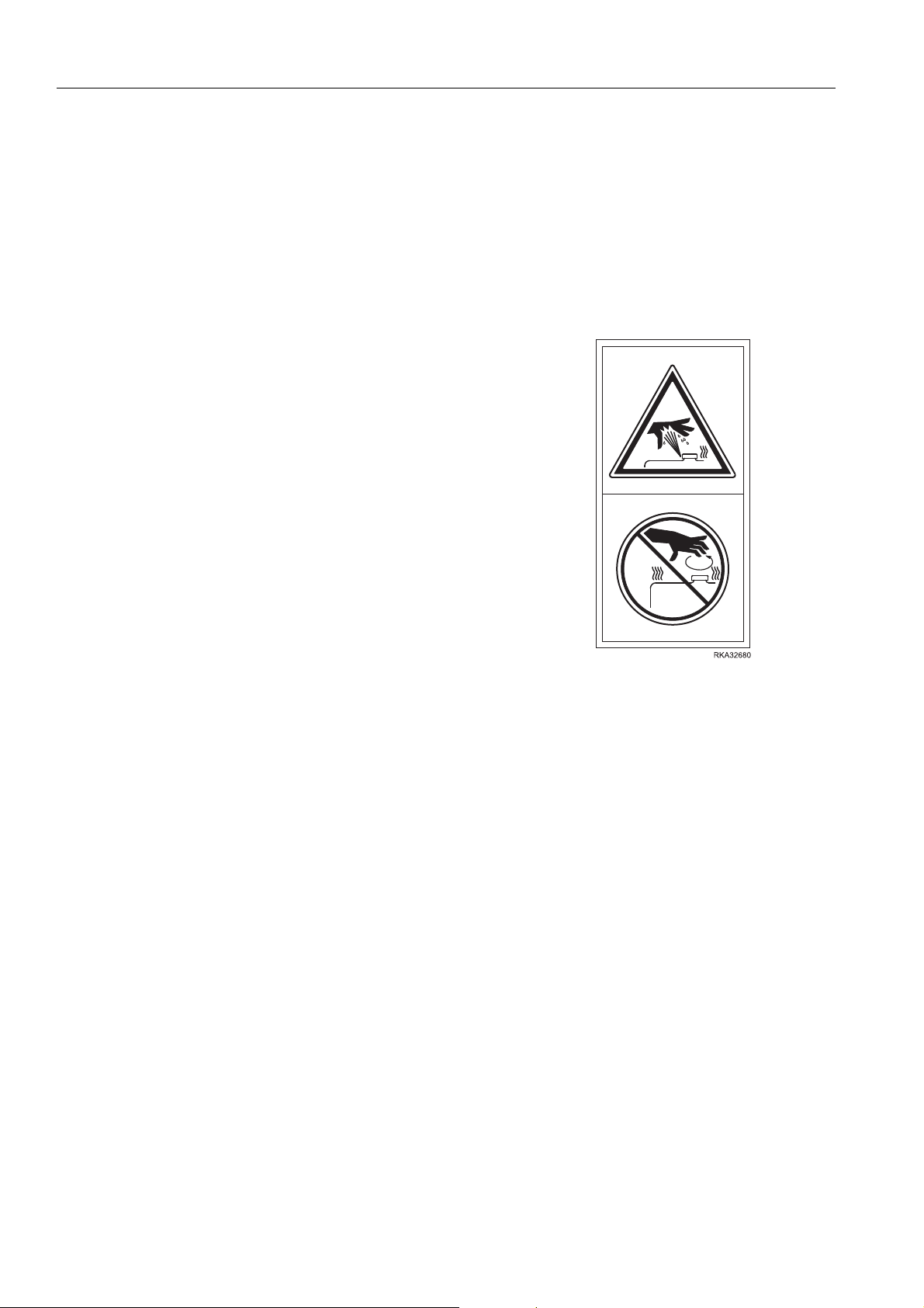
Safety labels using pictogram
Safety pictogra ms use a picture to expres s a level of
hazardous condition equivalent to the signal word. These
safety pictograms use pictures in order to let the operator or
maintenance worker understand the level and type of
hazardous condition at all times.
Safety pictograms show the type of hazardous condition at the
top or left side, and the method of avoidin g the hazardous
condition at the botto m or right side. In addition, t he type of
hazardous condition is displayed inside a triangle and the
method of avoidi ng the haza rdous con dition is shown ins ide a
circle.
FOREWORD
Komatsu cannot predict every circumstance that might involve a potential hazard in operation and maintenance.
Therefore, the saf ety messages in th is manual and on the machine may not include all po ssible safety
precautions.
If any procedures or actions not specifically recommended or allowed in this manual are used, it is your
responsibility to take the necessary steps to ensure safety.
In no event should you engage in prohibited uses or actions described in this manual.
The explanations, valu es, and ill ustrati ons in th is man ual were pr epared ba sed on th e lates t infor mation avail able
at that time. Some illu strati ons may be di fferent from the details of the ma chine in your poss ession: this is du e to
the continuous improvements made to the machines. Consult Komatsu or your Komatsu distributor for the latest
available information of your machine or for questions regarding information in this manual.
The numbers in circles in the illustrations correspond to the numbers in ( ) in the text. (For example: (1))
1-6
FOREWORD
ISO 6396
WEAM014802
SAFETY INFORMATION
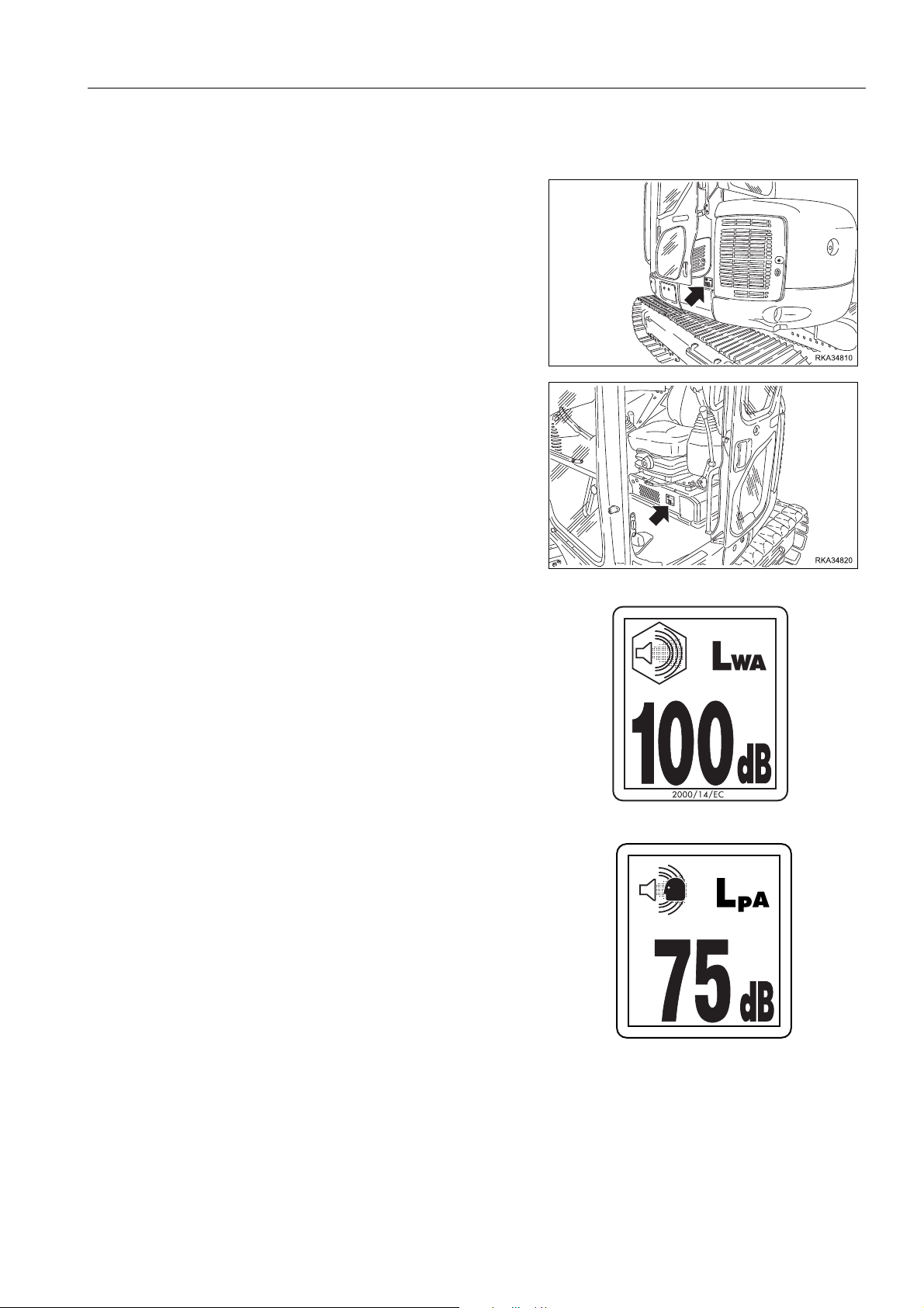
NOISE LEVELS 1
q The noise plates must always be legible and in good
conditions; for this reason, if they are dirty with dust, oil or
grease, it is neces sary to cle an them wit h a soluti on made
of water and detergent. Do not use fuel, petrol or solvents.
q If the plates are damaged, ask for new ones to Komatsu or
to your Komatsu distributor.
q In case of replacement of a component provided with a
noise plate, make sure that such a plate is applied also to
the new part.
q Sound power level emitted by the machine, measured
according to ISO 6395 (Dynamic test method, simulated
working cycle).
This is the guara nteed value as specified in Eur opean
directive 2000/14/EC. This value includes an uncertainty-of
1.6 dB.
q Sound pressure leve l at the operator’s station, measured
according to ISO6396 (Dyn amic test method , simulated
working cycle).
The maximum value of the standard deviation of the
measured time-a veraged A-weighted emission sound
pressure level at the operator’s position is 2.5 dB, in
accordance with ISO 11201.
1-7

SAFETY INFORMATION
WEAM014802
FOREWORD
VIBRATIONS TO WHICH THE OPERATOR IS SUBJECTED 1
When the earth moving machine is used for its intended purpose, the vibration levels transmitted from the
operator's seat are le ss than or equa l to the vi brati on test ed on the r elated class of mac hinery i n acco rdanc e with
ISO7096.
The actual acceleration value for the hands and arms is less than or equal to 2.5 m/s², the factor of uncertainty for
this vibration value is 1.2 m/s² according EN 12096: 1997.
The actual acceler ation value for the body is less than or equal t o 0.5 m/s², the factor of uncertainty for this
vibration value is 0.2 m/s² according EN 12096: 1997.
These values were determined using a representative machine and measured during the typical operating
condition indicated below according to the measurement procedures that are defined in the standards ISO 2631/1
and ISO 5349.
OPERATING CONDITION 1
Excavating (Digging-loading-rotating-unloading-rotating).
GUIDE TO REDUCE VIBRATION LEVELS ON MACHINE 1
The following guides can help an operator of this machine to reduce the whole body vibration levels:
1. Use the correct equipment and attachments.
2. Maintain the machine according to this manual.
Q Tension of crawler (for crawler machines).
Q Brake and steering systems.
Q Controls, hydraulic system and linkages.
3. Keep the terrain where the machine is working and travelling in good condition.
Q Remove any large rocks or obstacles.
Q Fill any ditches and holes.
Q Site manager should provide machine operators with machine and schedule time to maintain terrain
conditions.
4. Use a seat that meets ISO 7096 and keep the seat maintained and adjusted.
Q Adjust the seat and suspension for the weight and size of the operator.
Q Wear seat belt.
Q Inspect and maintain the seat suspension and adjustment mechanisms.
5. Steer, brake, accelerate, and move the attachment levers and pedals slowly so that the machine moves
smoothly.
6. Adjust the machine speed and travel path to minimize the vibration level.
Q When pushing with bucket or blade, avoid sudden loading; load gradually.
Q Drive around obstacles and rough terrain conditions.
Q Slow down when it is necessary to go over rough terrain.
Q Make the curve radius of travelling path as large as possible.
Q Travel at low speed when travelling around sharp curves.
1-8

FOREWORD
WEAM014802
7. Minimize vibrations for long work cycle or long distance travelling.
Q Reduce speed to prevent bounce.
Q Transport machines long distances between worksites.
8. The following guidelines can be effective to minimize risks of low back pain.
Q Operate the machine only when you are in good health.
Q Provide breaks to reduce long periods of sitting in the same posture.
Q Do not jump down from the cab or machine.
Q Do not repeatedly handle and lift loads.
SAFETY INFORMATION
GUIDE WHEN WORKING IN AREAS WHERE AIR POLLUTION 1
When working in area s wh er e air po ll uti on i s c ons id er abl e ( tunn el s, d usty places, small or bad ly ve nti lated rooms,
etc.) use the air conditioning with the internal air rec irculation function selected. (For details, see "AIR
CONDITIONER (3-87)").
1-9

INTRODUCTION
WARNING
WARNING
WEAM014802
FOREWORD
INTRODUCTION 1
This Komatsu machine is designed to be used mainly for the following work:
q Digging work
q Leveling work
q Ditching work
q Loading work
See paragraph "OPERATIONS THAT CAN BE PERFORMED WITH THE HYDR AULIC EXC AVATOR (3-164)" for
further details.
q Occasional lifting and handl ing of the objects. For details see LIFTING OBJECTS WITH LIFTING DE VICE
(OPTIONAL EQU IPMENT) (2-47).
The excavator used in handling operations must conform with current local regulations and be equipped
with safety valves and an overload alarm in compliance with EN 474-5.
DEMOLITION WORK 1
q A demolition machine is a machine based on earth
moving machinery (see EN ISO 6165) and including
equipment and attachment (working tool - e.g.
processor or breaker) specifically designed to
demolish, cut, loosen, separate, pick up, transport and
distribute component parts of buildings or civil
engineering structures.
q This machine is not prepared for use in Demolition.
q Using this machine in demolition work gives an
increased risk of serious injury or death.
q All Komatsu machinery that have been specifically
designed for, and can be used in, demolition work, will
display the Komatsu demolition decal.
q If the machine does not display this decal and it is
necessary to carry out demolition work, contact your
distributor for information on demolition machine ry
compliant with the applicable standards.
1-10

FOREWORD
CAUTION
NOTICE
WEAM014802
INTRODUCTION
IMPROPER OR UNAUTHORIZED USES 1
This paragraph describes some of the improper or unauthorized uses of the machine; since it is
impossible to predict all the possible improper uses, if it is necessary to use the machine for particular
applications, contact your Komatsu distributor before carrying out the work.
q The instructions regarding the authorized optional equipment are given in the relevant operation and
maintenance manuals; if the equipment is supplied by Komatsu, these publications are enclosed to
this manual.
q The instructions regarding the assembly of the authorized equipment, the controls requiring special
arrangements on the machine and the hydraulic couplings neces sary for the operation of such
equipment are grouped in the final section of this manual.
Komatsu machines are constructed exclusively for the handling, excavation and treatment of i nert materials;
therefore, the following uses are absolutely forbidden:
q Use of the machine by minors or inexperienced persons.
q Use of the machine for the lifting of people
q Transport of containers with flammable or dangerous fluids.
q Use of the bucket for driving or extracting piles.
q Use of the machine for towing.
q Use of the machine in tunnels/underground in explosive environments.
MAIN CHARACTERISTICS 1
q Simple and easy operation.
q Hydrostatic transmissi on obtained through two var iable displacemen t motors that operate epi cyclic reduction
gears equipped with negative hydraulic brakes.
q Rotation of the turret achieved by means of an axial piston hydra ulic motor acting on an epicyc lic reduction
gear.
q Ball-bearing ring teeth and pinion lubricated in grease bath.
q Main equipment con trolled through servo levers ensu ring also combin ed movements that can be modulated
proportionally and continually.
q Boom swing and trav el control s with s ervo pedals ensur ing movements th at can be modulated proporti onally
and continuously.
q Travel speed increase function controlled with a button.
q Servo-assisted controls for blade
q Complete series of instruments visible from the operating position.
q Hand accelerator.
q Easy maintenance with simplifie d interv als .
1-11

INTRODUCTION
WEAM014802
FOREWORD
RUNNING-IN 1
All machines have been meticulously adjusted and tested before delivery.
However, a new machine must be used with caution during the first 100 hours, for a correct running in of the
different components.
If the machine is subjected to excessive work load at the beginning of operation, its potential productivity and its
functionality will be shortly and untimely reduced. For more details, see "Running-in (3-136)".
1-12
FOREWORD
WEAM014802
INTRODUCTION
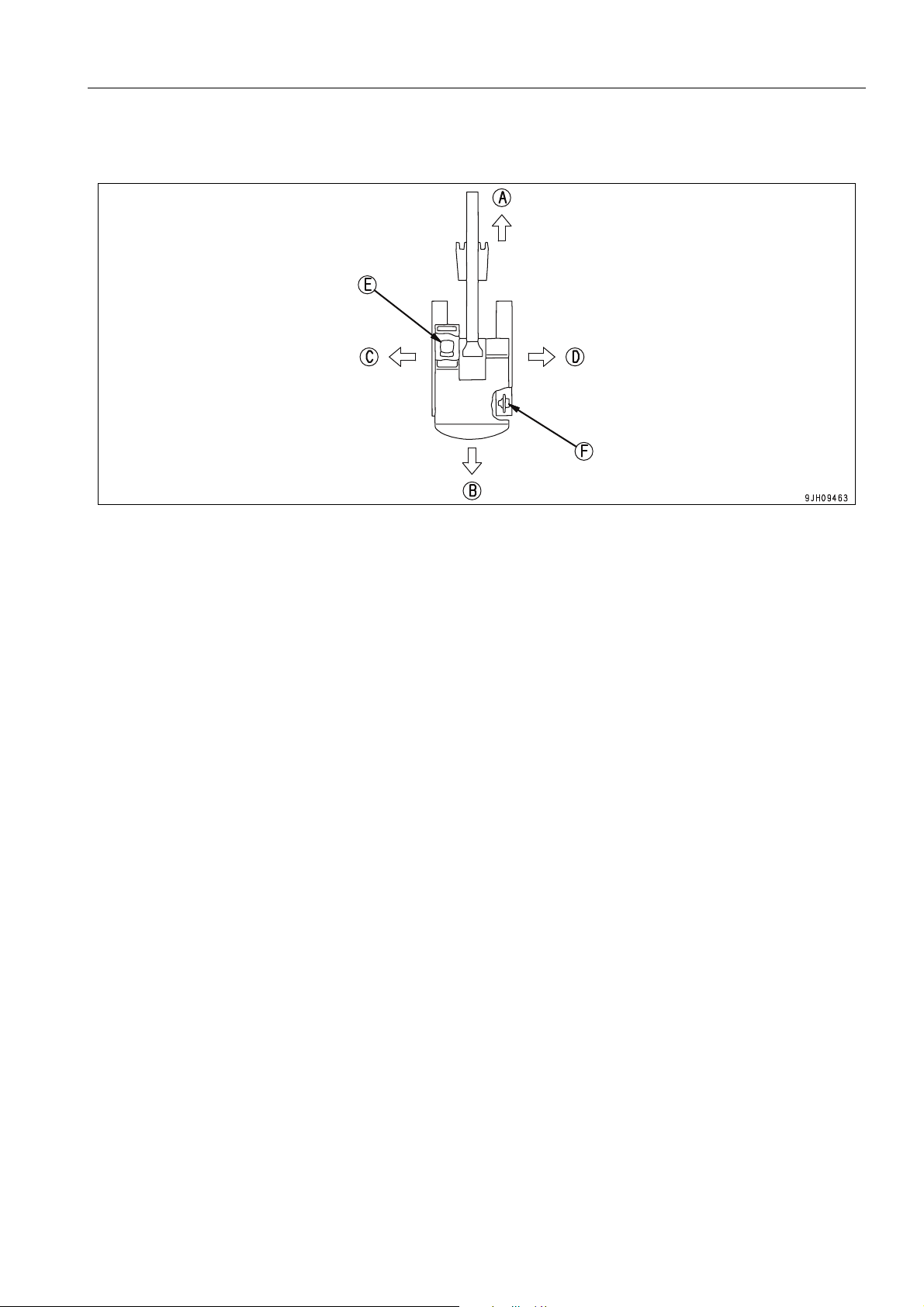
DIRECTIONS OF MACHINE 1
(E)
Forwards
(A)
Backwards
(B)
Left
(C)
Right
(D)
In this manual, the terms front, rear, left, and right refer to the travel directio n as seen from the operator's seat
when the operator's seat is facing the front and the sprocket (F) is at the rear of the machine.
Operator seat
(F)
Sprocket
1-13
PRODUCT IDENTIFICATION
WEAM014802
FOREWORD
PRODUCT IDENTIFICATION
The Komatsu excavator and its main components are identified by serial numbers stamped on the identification
plates. The serial number and the identification numbers of the components are the only numbers that must be
communicated to the distributor when requiring assistance and ordering spare parts.
MACHINE SERIAL NUMBER 1
The machine serial number is stamped on the front upper part
of the main frame, on the left side.
MACHINE IDENTIFICATION PLATE AND PRODUCT IDENTIFICATION NUMBER (P IN) 1
The Komatsu excavators described in this manual are CE
marked, in fact they are in com pli an ce with the EU har m oni se d
standards.
The plate with the CE marking is applie d to the fr ont wall of the
main frame, on the left side.
1-14
FOREWORD
WEAM014802
PRODUCT IDENTIFICATION
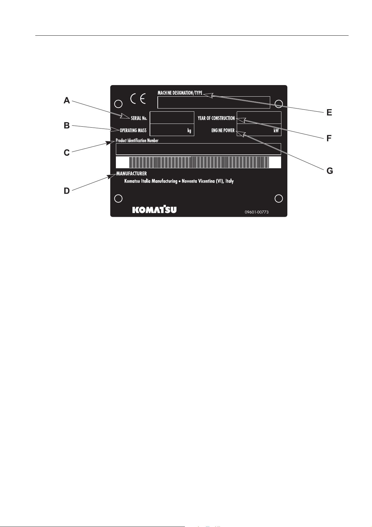
MACHINE SERIAL NUMBER PLATE
(according directive 2006/42/EC) 1
(A) Serial number (E) Machine designation type
(B) Operating mass (F) Year of manufacture
(C) Product identification number (G) Engine power
(D) Manufacturer
1-15
PRODUCT IDENTIFICATION
WEAM014802
FOREWORD
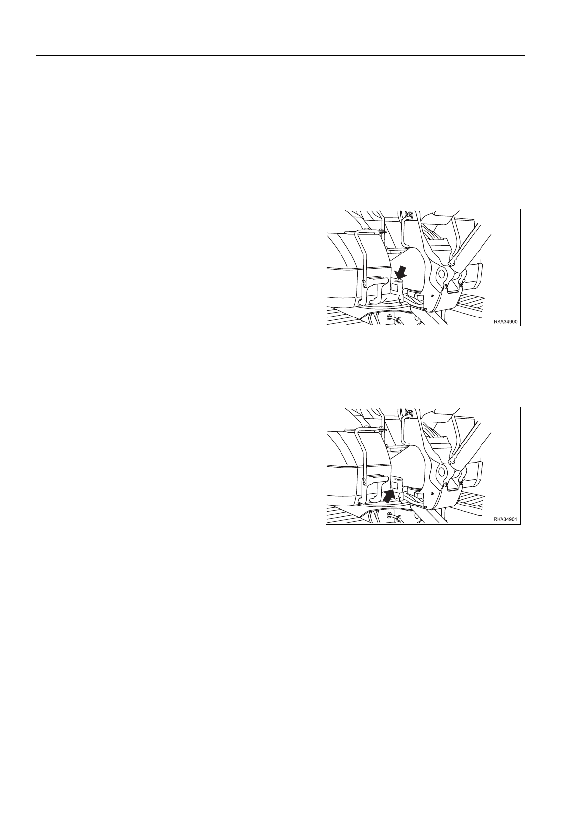
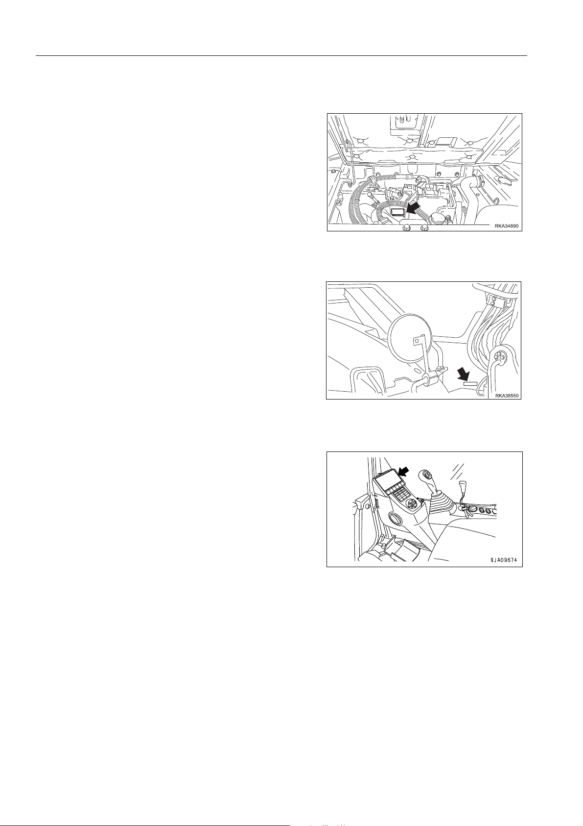
ENGINE SERIAL NUMBER AND EXHAUST GAS EMISSION PLATE 1
The serial number and the exhaust gas emis sion plate are
located on the fuel filter support.
CAB SERIAL NUMBER 1
The serial number is stamped on the plate positioned on the
external right hand side of the cab.
HOUR COUNTER POSITION 1
The hour counter is positioned on the machine panel.
1-16

FOREWORD
WEAM014802
PRODUCT IDENTIFICATION
TABLE TO ENTER SERIAL NO. AND DISTRIBUTOR 1
Machine serial No.
Engine serial No.
Product identification number
(PIN)
Manufacturers name:
Address:
Authorised Representative:
Address:
Distributor name:
Address:
Service Personnel
Phone/Fax
Komatsu Italia Manufacturing S.p.A.
Via Atheste, 4
35042 Este (PD) Italy
DECLARATION OF CONFORMITY (for machines placed on the market as from 29 December 2009) 1
The Manufac turer:
Komatsu I talia Manufacturin g S.p.A.
Via Atheste, 4
35042 Este (PD) Italy
Declares that this machine:
PC118MR-8
Fulfils all the relevant provisions of following EC Directive:
Machinery Directive 2006/42/EC
Electro Magnetic Compatibility Directive
Outdoor Noise Directive 2000/14/EC amended 2005/88/EC
Radio Equipment and Telecommunications Terminal
Equipment Directive
Radio Equipment Directive 2014/53/EU after 13 June 2016
2004/108/EC until 19 April 2016
2014/30/EU after 20 April 2016
1999/5/EC until 12 June 2016
1-17

CONTENTS
WEAM014802
CONTENTS
FOREWORD.........................................................................................................................................................1-2
SAFETY INFORMATION...................................................................................................................................... 1-4
NOISE LEVELS .......................................................................................................................................... 1-7
VIBRATIONS TO WHICH THE OPERATOR IS SUBJECTED...................................................................1-8
GUIDE WHEN WORKING IN AREAS WHERE AIR POLLUTION.............................................................. 1-9
INTRODUCTION.................................................................................................................................................1-10
DEMOLITION WORK ..................................... ...... ....... ...... ............................................. ..........................1-10
IMPROPER OR UNAUTHORIZED USES................................ ...... ...... ....... ...... ....................................... 1-11
MAIN CHARACTERISTICS......................................................................................................................1-11
RUNNING-IN ............................................................................................................................................1-12
DIRECTIONS OF MACHINE ....................................................................................................................1-13
PRODUCT IDENTIFICATION............................................................................................................................. 1-14
MACHINE SERIAL NUMBER...................................................................................................................1-14
MACHINE IDENTIFICATION PLATE AND PRODUCT IDENTIFICATION NUMBER (PIN)..................... 1-14
MACHINE SERIAL NUMBER PLATE
(according directive 2006/42/EC)..............................................................................................................1-15
ENGINE SERIAL NUMBER AND EXHAUST GAS EMISSION PLATE.................................................... 1-16
CAB SERIAL NUMBER ............................................................................................................................ 1-16
HOUR COUNTER POSITION ..................................................................................................................1-16
TABLE TO ENTER SERIAL NO. AND DISTRIBUTOR ............................................................................1-17
DECLARATION OF CONFORMITY
(for machines placed on the market as from 29 December 2009)............................................................1-17
SAFETY LAB EL S.................................................................................................................................................2-2
LOCATION OF SAFETY LABELS..............................................................................................................2-3
SAFETY LABELS .......................................................................................................................................2-4
SAFETY RULES.......................................................................................................................................2-17
IF PROBLEMS ARE FOUND.................................................................................................................... 2-17
WORKING WEAR AND PERSONAL PROTECTIVE ITEMS ................................................................... 2-17
FIRE EXTINGUISHER AND FIRST AID KIT ............................................................................................2-18
SAFETY EQUIPMENT..............................................................................................................................2-18
KEEP MACHINE CLEAN.......................................................................................................................... 2-18
KEEP OPERATOR'S COMPARTMENT CLEAN......................................................................................2-19
LEAVING THE OPERATOR’S SEAT .......................................................................................................2-19
HANDRAILS AND STEPS........................................................................................................................2-20
MOUNTING AND DISMOUNTING ...........................................................................................................2-20
IT IS FORBIDDEN TO CLIMB ON THE EQUIPMENT ............................................................................. 2-20
DO NOT GET CAUGHT IN ARTICULATED PORTION ...........................................................................2-21
BURN PREVENTION ...............................................................................................................................2-21
FIRE PREVENTION AND EXPLOSION PREVENTION....................... ....... ...... ....... ................................ 2-22
ACTION IF FIRE OCCURS ...................................................................................................................... 2-23
WINDSHIELD WASHER FLUID ............................................................................................................... 2-23
FALLING OBJECTS, FLYING OBJECTS AND INTRUDING OBJECTS PREVENTION .........................2-24
1-18

CONTENTS
WEAM014802
CAUTIONS RELATED TO ROPS............................................................................................................. 2-24
ATTACHMENT INSTALLATION............................................................................................................... 2-25
ATTACHMENT COMBINATIONS............................................................................................................. 2-25
PREVENTING DAMAGE CAUSED BY THE WORK EQUIPMENT ......................................................... 2-25
CAB WINDOW GLASSES........................................................................................................................ 2-25
UNAUTHORIZED MODIFICATIONS........................................................................................................ 2-25
SAFETY AT JOBSITE ... ...... ....... .............................................................................................................. 2-26
WORKING ON LOOSE GROUND............................................................................................................2-26
DISTANCE TO HIGH VOLTAGE CABLES............................................................................................... 2-27
ENSURE GOOD VISIBILITY.................................................................................................................... 2-28
VENTILATION FOR ENCLOSED AREA .................................................................................................. 2-28
SIGNALMAN'S SIGNAL AND SIGNS....................................................................................................... 2-29
EMERGENCY EXIT FROM OPERATOR'S CAB ..................................................................................... 2-34
ASBESTOS DUST HAZARD PREVENTION............................................................................................ 2-34
SAFETY MACHINE OPERATION...................................................................................................................... 2-35
STARTING ENGINE................................................................................................................................. 2-35
FUNCTIONING......................................................................................................................................... 2-37
TRANSPORTING THE MACHINE............................................................................................................ 2-43
BATTERY ................................................................................................................................................. 2-44
TOWING................................................................................................................................................... 2-46
LIFTING OBJECTS WITH LIFTING DEVICE (OPTIONAL EQUIPMENT)............................................... 2-47
SAFETY MAINTENANCE INFORMATION........................................................................................................ 2-50
MACHINE ILLUSTRATIONS................................................................................................................................3-2
GENERAL VIEW OF THE MACHINE WITH MONOBOOM ....................................................................... 3-2
GENERAL VIEW OF THE MACHINE WITH TWO-PIECE BOOM............................................................. 3-3
CONTROLS AND GAUGES....................................................................................................................... 3-4
INSTRUMENTS AND CONTROLS ...................................................................................................................... 3-6
MONITOR MESSAGE................................................................................................................................ 3-6
MONITORING SYSTEM............................................................................................................................. 3-8
SWITCHES AND PUSH BUTTONS ......................................................................................................... 3-62
CONTROL LEVERS AND PEDALS ........................................ ................................................................. 3-69
CAB .................................................................................................................................................................... 3-75
OPENING ROOF...................................................................................................................................... 3-75
WINDSHIELD ........................................................................................................................................... 3-76
SLIDING DOOR........................................................................................................................................ 3-81
EMERGENCY EXIT HAMMER................................................................................................................. 3-82
HOODS AND DOORS FITTED WITH A LOCK ................................................................................................. 3-83
ENGINE COVER ...................................................................................................................................... 3-84
SIDE COVER............................................................................................................................................ 3-85
PUMP COMPARTMENT AND BATTERY COMPARTMENT DOORS..................................................... 3-86
AIR CONDITIONER............................................................................................................................................ 3-87
AIR CONDITIONER CONTROL PANEL .................................................................................................. 3-88
OPERATING MODES............................................................................................................................... 3-92
1-19

CONTENTS
WEAM014802
USE THE AIR CONDITIONER WITH CAUTION......................................................................................3-99
INSPECTING AND SERVICING A MACHINE WITH AIR CONDITIONER . ...... ....... ...... ....... ...... .............3-99
FUSES .............................................................................................................................................................. 3-100
MAIN FUSE ............................................................................................................................................3-101
SUPPLEMENTARY POWER SUPPLY............................................................................................................ 3-102
CONTROLLER ................................................................................................................................................. 3-104
STORAGE COMPARTMENTS.........................................................................................................................3-105
TECHNICAL DOCUMENTATION COMPARTMENT.............................................................................. 3-105
CUP HOLDER ........................................................................................................................................3-105
TOOL BOX.............................................................................................................................................. 3-105
PUMP SUPPORT FOR GREASING .......................................................................................................3-106
ASHTRAY...............................................................................................................................................3-106
FIRE EXTINGUISHERS ......................................................................................................................... 3-106
KOMTRAX SYSTEM ........................................................................................................................................3-107
GENERAL PRECAUTIONS.................................................................................................................... 3-107
USE OF THE MACHINE AND RELATED CONTROLS...................................................................................3-109
BEFORE STARTING THE ENGINE.......................................................................................................3-109
AFTER STARTING THE ENGINE.......................................................................................................... 3-135
STOPPING THE ENGINE ......................................................................................................................3-146
HOW TO MOVE THE MACHINE............................................................................................................3-147
STEERING THE MACHINE.................................................................................................................... 3-150
TURRET ROTATION..............................................................................................................................3-152
WORK EQUIPMENT CONTROLS AND FUNCTIONS...........................................................................3-153
WORK MODE.........................................................................................................................................3-155
UNAUTHORIZED OPERATIONS...........................................................................................................3-156
PRECAUTIONS FOR USE..................................................................................................................... 3-159
PRECAUTIONS TO BE TAKEN WHEN TRAVELLING ON SLOPES....................................................3-161
GETTING THE MACHINE OUT OF MUD .............................................................................................. 3-163
OPERATIONS THAT CAN BE PERFORMED WITH THE HYDRAULIC EXCAVATOR ........................3-164
LIFTING OBJECTS WITH LIFTING DEVICE .........................................................................................3-166
BUCKET REPLACEMENT AND INVERSION........................................................................................ 3-169
PARKING THE MACHINE......................................................................................................................3-170
CHECKS TO BE CARRIED OUT BEFORE STOPPING THE ENGINE................................................. 3-171
CHECKS TO BE CARRIED OUT AFTER WORK .................................................................................. 3-172
LOCKING THE MACHINE......................................................................................................................3-172
ROAD LINERS........................................................................................................................................3-173
TRANSPORTATION.........................................................................................................................................3-176
TRANSPORT PROCEDURE..................................................................................................................3-176
LOADING AND UNLOADING THE MACHINE.......................................................................................3-177
LIFTING THE MACHINE ...................................... ....... ............................................. .............................. 3-182
USING THE MACHINE IN THE COLD SEASON.............................................................................................3-184
PRECAUTIONS TO BE TAKEN WHEN USING THE MACHINE IN THE COLD SEASON ...................3-184
1-20

CONTENTS
WEAM014802
PRECAUTIONS TO BE TAKEN EVERY DAY AT THE END OF WORK............................................... 3-186
HOW TO PROCEED AT THE END OF THE COLD SEASON............................................................... 3-186
LONG PERIODS OF INACTIVITY.................................................................................................................... 3-187
BEFORE A PERIOD OF INACTIVITY .................................................................................................... 3-187
DURING A PERIOD OF INACTIVITY..................................................................................................... 3-187
RECOMMENDATIONS FOR MACHINES EQUIPPED WITH KOMTRAX SYSTEM DURING LONG
PERIODS OF INACTIVITY..................................................................................................................... 3-188
AFTER A PERIOD OF INACTIVITY .......................................................................................................3-188
ENGINE START-UP AFTER PROLONGED INACTIVITY...................................................................... 3-189
ALLOWED AMBIENT TEMPERATURE RANGE DURING THE OPERATION AND STORAGE OF THE
MACHINE FOR A LONG TIME............................. ............................................. ..................................... 3-189
TROUBLESHOOTING...................................................................................................................................... 3-190
IF FUEL RUNS OUT COMPLETELY...................................................................................................... 3-190
OCCURRENCES THAT ARE NOT FAILURES......................................................................................3-190
REMOVING THE MACHINE................................................................................................................... 3-191
PRECAUTIONS TO BE TAKEN WHEN WORKING IN PARTICULAR CONDITIONS................ ...... ..... 3-191
IF THE BATTERY IS DOWN .................................................................................................................. 3-192
OTHER TROUBLES............................................................................................................................... 3-197
GUIDE TO MAINTENANCE ................................................................................................................................. 4-2
MAINTENANCE NOTES ............................................................................................................................ 4-5
OIL, FUEL, COOLANT AND GREASE.......................................................................................................4-5
KOWA (KOMATSU OIL WEAR ANALYSIS)............................................................................................... 4-8
STORING OIL AND FUEL.......................................................................................................................... 4-9
FILTERS..................................................................................................................................................... 4-9
NOTES ON THE MAINTENANCE OF THE ELECTRICAL SYSTEM......................................................... 4-9
NOTES ON THE MAINTENANCE OF THE HYDRAULIC SYSTEM........................................................ 4-10
MAINTENANCE NOTES REGARDING LUBRICATION .......................................................................... 4-10
PARTS SUBJECT TO WEAR............................................................................................................................ 4-11
LIST OF THE PARTS SUBJECT TO WEAR............................................................................................ 4-11
FUEL, COOLANT AND LUBRICANTS.............................................................................................................. 4-12
RECOMMENDED BRANDS, QUALITY RECOMMENDED FOR PRODUCTS DIFFERENT THAN ORIGINAL
KOMATSU OIL ......................................................................................................................................... 4-13
APPROVED SYNTHETIC BIODEGRADABLE LUBRICANTS TYPE HEES............................................ 4-14
TIGHTENING TORQUES................................................................................................................................... 4-15
STANDARD TIGHTENING TORQUES FOR SCREWS AND NUTS .......................................... ...... ....... 4-15
STANDARD TIGHTENING TORQUES FOR FLEXIBLE HOSES (ORFS).............. ................................. 4-16
LUBRICATION ................................................................................................................................................... 4-17
LUBRICATION DIAGRAM....................................................... ...... ....... ...... .............................................. 4-17
BOOM....................................................................................................................................................... 4-17
2-PIECE BOOM............. ...... ....... ............................................. ................................................................. 4-18
PERIODICAL CHANGE OF SAFETY-RELATED COMPONENTS................................................................... 4-19
SAFETY-RELATED PARTS..................................................................................................................... 4-20
1-21

CONTENTS
WEAM014802
MAINTENANCE PLAN.......................................................................................................................................4-21
MAINTENANCE PLAN .............................................................................................................................4-21
MAINTENANCE INTERVALS IN CASE OF USE OF THE HYDRAULIC BREAKER............................... 4-23
MAINTENANCE PROCEDURES ....................................................................................................................... 4-24
WHEN REQUIRED...................................................................................................................................4-24
CHECKS TO BE CARRIED OUT BEFORE STARTING THE ENGINE....................................................4-44
MAINTENANCE AFTER THE FIRST 50 HOURS OF OPERATION ........................................................4-44
MAINTENANCE EVERY 100 HOURS OF OPERATION ......................................................................... 4-45
MAINTENANCE EVERY 250 HOURS OF OPERATION ......................................................................... 4-47
MAINTENANCE AFTER THE FIRST 500 HOURS OF OPERATION ......................................................4-54
MAINTENANCE EVERY 500 HOURS OF OPERATION ......................................................................... 4-54
MAINTENANCE EVERY 1000 HOURS OF OPERATION ....................................................................... 4-69
MAINTENANCE EVERY 2000 HOURS OF OPERATION ....................................................................... 4-74
MAINTENANCE EVERY 4000 HOURS OF OPERATION ....................................................................... 4-87
MAINTENANCE EVERY 5000 HOURS OF OPERATION ....................................................................... 4-89
FINAL DISPOSAL OF THE MACHINE ..............................................................................................................4-92
SPECIFICATIONS................................................................................................................................................5-2
OPERATING CHARACTERISTICS ..................................................................................................................... 5-3
LIFTING CAPACITIES TABLES..........................................................................................................................5-5
LEGENDE...................................................................................................................................................5-5
LIFTING CAPACITIES WITH BOOM.......................................................................................................... 5-6
LIFTING CAPACITIES WITH TWO-PIECE BOOM ....................................................................................5-9
GENERAL PRECAUTIONS FOR SAFETY.......................................................................................................... 6-2
PRECAUTIONS WHEN SELECTING......................................................................................................... 6-2
READ THE INSTRUCTION MANUAL THOROUGHLY..... ....... ...... ...... .............................................. ........6-2
PRECAUTIONS WHEN REMOVING OR INSTALLING ............................................................................. 6-2
PRECAUTIONS WHEN USING..................................................................................................................6-2
SPECIFICATIONS................................................................................................................................................6-4
ARM-PIN INFORMATION...........................................................................................................................6-4
EQUIPMENT USE GUIDE....................................................................................................................................6-5
COMBINATIONS OF WORK EQUIPMENT................................................................................................ 6-5
EQUIPMENT CONFIGURATION ...............................................................................................................6-5
LONG ARM.................................................................................................................................................6-7
MACHINE CONFIGURATION FOR THE INSTALLATION OF ATTACHMENTS....................................... 6-8
HYDRAULIC QUICK COUPLER........................................................................................................................ 6-17
POSITION OF THE DEVICES..................................................................................................................6-17
FUNCTIONING......................................................................................................................................... 6-18
RECOMMENDED ATTACHMENT OPERATIONS............................................................................................. 6-20
HYDRAULIC BREAKER........................................................................................................................... 6-20
INSTALLING AND REMOVING THE ADDITIONAL COUNTERWEIGHT.........................................................6-25
1-22

SAFETY
WARNING
WEAM014802
12
Read and make sure that the precautions outlined in this manual and the safety labels on the machine
have been fully understood. Always closely observed these safety measures when starting or performing
assistance on the machine.

SAFETY LABELS
WEAM014802
SAFETY
SAFETY LABELS 2
The following warning signs and safety labels are used on this machine.
q Be sure that you fully understand the correct position and content of labels.
q To ensure that the content of labels can be read properly , be sure that they are in the correct place and always
keep them clean. When clea ning them , do not use organic solvents or gasoline. Th ese may cause the labels
to peel off.
q There are also other labels in addition to the warning signs and safety labels. Handle those labels in the same
way.
q If the labels are damaged, lost, or cannot be read properly, replace them with new ones. For details of the part
numbers for the labels, see this manual or the actual label, and place an order with Komatsu distributor.
2-2
SAFETY
WEAM014802
SAFETY LABELS
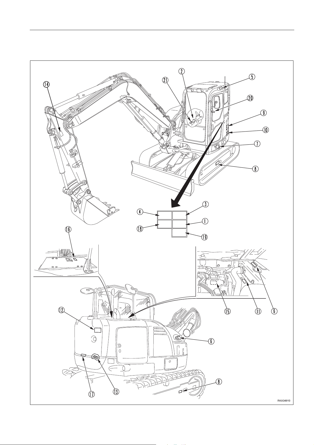
LOCATION OF SAFETY LABELS 2
2-3
SAFETY LABELS
WEAM014802
SAFETY
SAFETY LABELS 2
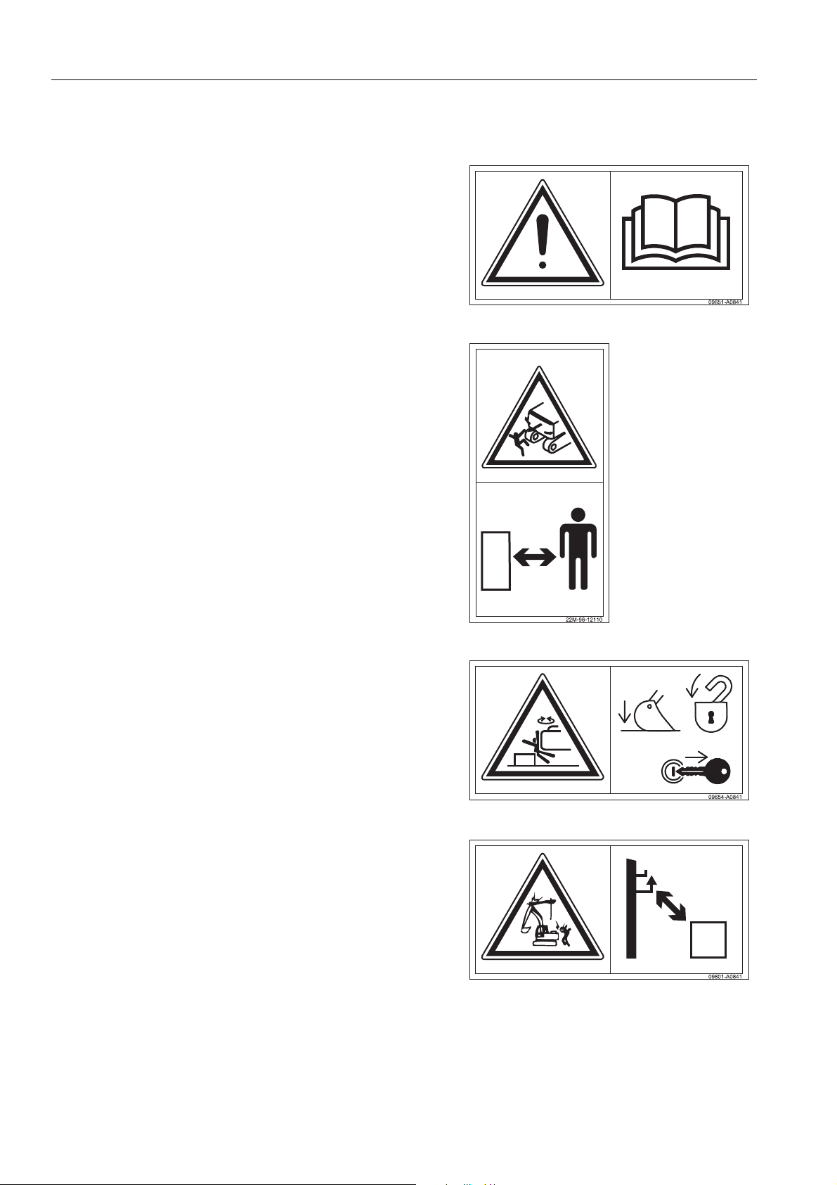
(1) Consult the manual.
q Carefully read the conten ts of the manual before us ing
the machine or performing maintenance operations.
(2) Safety distance.
q Do not get too near the machine and do not stand
within its operating range.
(3) Before leaving the operator’s seat
q Before leaving the ma chine , lower th e work eq uipmen t
to the ground, shift the safety lever to position “lock”,
stop the engine and remove the ignition key .
(4) Risk of electrocution
q Minimum safety distances from overhead lines. (For
details, see "DISTANCE TO HIGH VOLTAGE CABLES
(2-27)").
2-4
SAFETY
WEAM014802
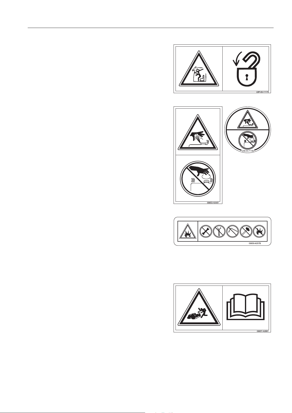
(5) Caution when stowing front window
q Make sure that the front windshield is always locked.
(6) Risk of burns
q Do not open the radiator and the hydraulic oil tank
when the engine is still hot.
SAFETY LABELS
(7) Risk of explosio n on the hydraulic accumulato r and gas
spring
q Working on the accumulator witho ut due caution may
cause explosion, leading to serious personal injury.
Always observe the followi ng prec auti on s:
- Do not dismantle
- Keep away from sparks and flame.
- Do not puncture and do not weld with oxyacetylene
torches
- Do not strike or crush
(8) Adjusting the track tension
q The adjustment of the tracks involves the risk of
injuries.
q To correctly and safely adjust the tracks, read the
instructions in the manual .
2-5
SAFETY LABELS
WEAM014802
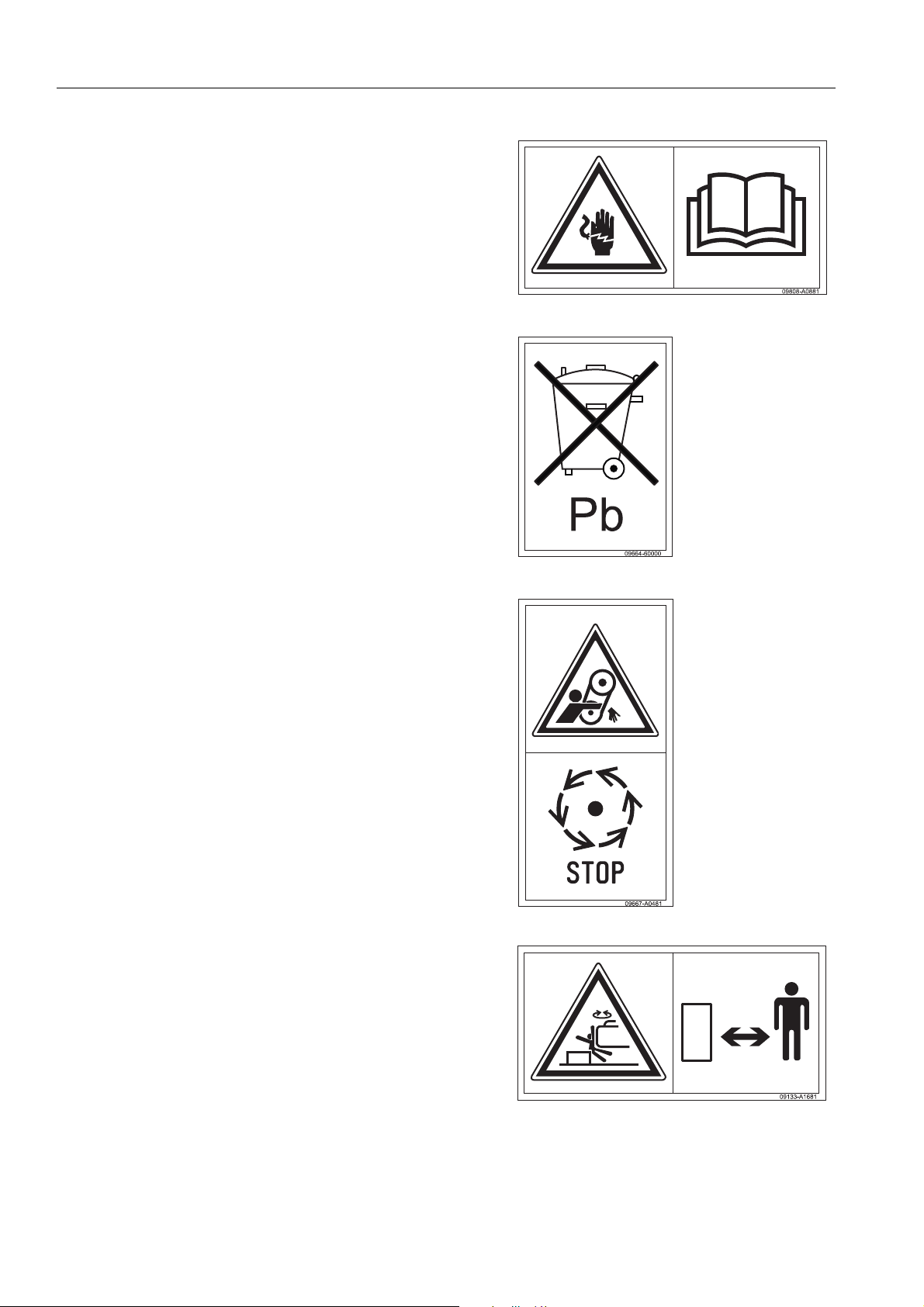
(9) Battery and electric cables
q Risk of electric charges in case of work on the battery
or the electric cables.
(10) Battery
q Precautions for working on the battery.
SAFETY
(11) Do not open the hood.
q Do not open or remove the hood when the engine is
running.
(12) Safety distance.
q Do not get too near the machine and do not stand
within the revolving frame swinging range.
2-6
 Loading...