

Kohler KT715, KT730, KT735, KT745, KT725 Service Manual
...
KT715-KT745
Service Manual
IMPORTANT: Read all safety precautions and instructions carefully before operating equipment. Refer to operating
instruction of equipment that this engine powers.
Ensure engine is stopped and level before performing any maintenance or service.
2 Safety
3 Maintenance
5 Specifi cations
12 Tools and Aids
15 Troubleshooting
19 Air Cleaner/Intake
20 Fuel System
27 Governor System
28 Lubrication System
30 Electrical System
36 Starter System
42 Emission Compliant Systems
45 Disassembly/Inspection and Service
57 Reassembly
132 690 03 Rev. --
Safety
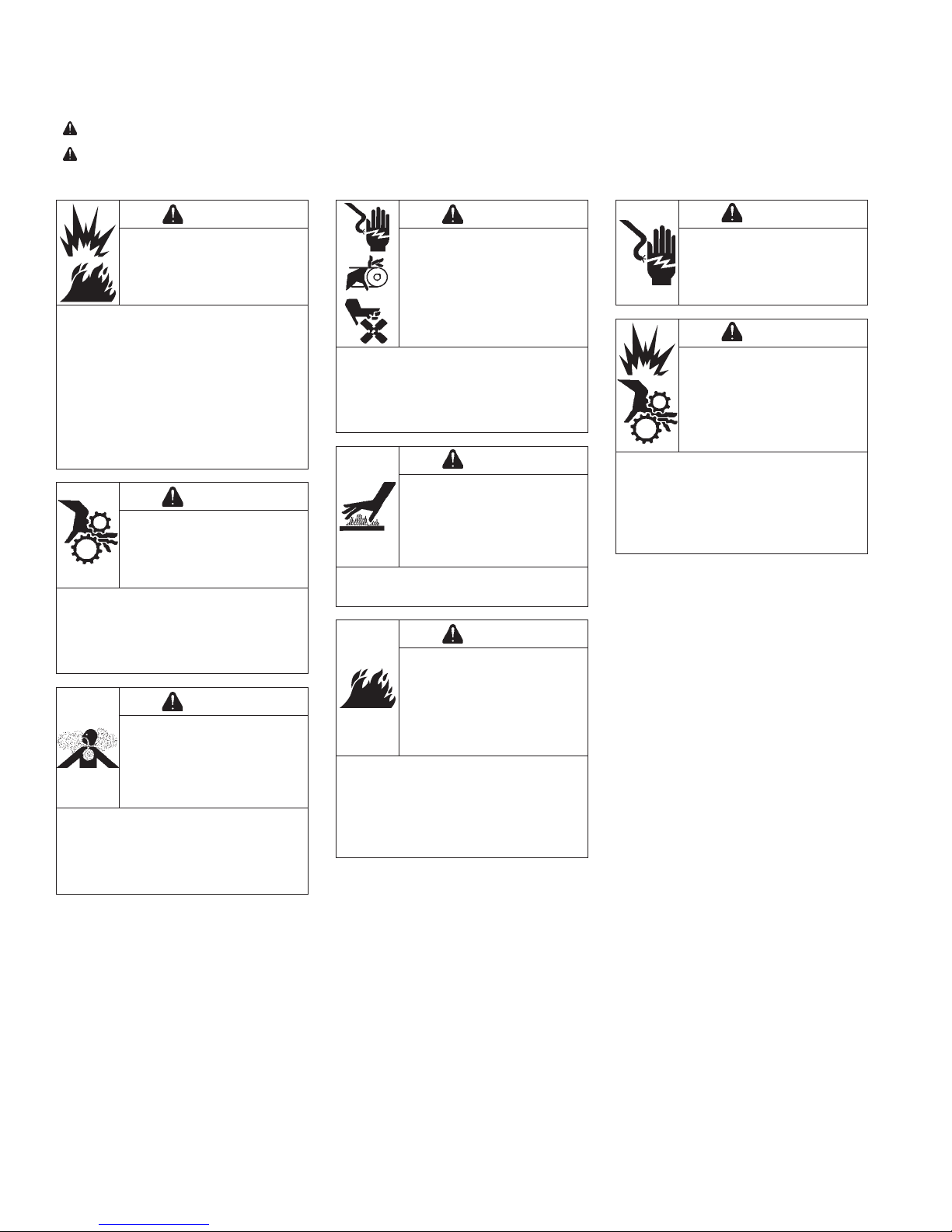
SAFETY PRECAUTIONS
WARNING: A hazard that could result in death, serious injury, or substantial property damage.
CAUTION: A hazard that could result in minor personal injury or property damage.
NOTE: is used to notify people of important installation, operation, or maintenance information.
WARNING
Explosive Fuel can cause
fi res and severe burns.
Do not fi ll fuel tank while
engine is hot or running.
Gasoline is extremely fl ammable
and its vapors can explode if
ignited. Store gasoline only in
approved containers, in well
ventilated, unoccupied buildings,
away from sparks or fl ames.
Spilled fuel could ignite if it comes
in contact with hot parts or sparks
from ignition. Never use gasoline
as a cleaning agent.
WARNING
Rotating Parts can cause
severe injury.
Stay away while engine
is in operation.
Keep hands, feet, hair, and
clothing away from all moving
parts to prevent injury. Never
operate engine with covers,
shrouds, or guards removed.
WARNING
Carbon Monoxide can
cause severe nausea,
fainting or death.
Avoid inhaling exhaust
fumes.
Engine exhaust gases contain
poisonous carbon monoxide.
Carbon monoxide is odorless,
colorless, and can cause death if
inhaled.
Accidental Starts can
cause severe injury or
death.
Disconnect and ground
spark plug lead(s) before
servicing.
Before working on engine or
equipment, disable engine as
follows: 1) Disconnect spark plug
lead(s). 2) Disconnect negative (–)
battery cable from battery.
Hot Parts can cause
severe burns.
Do not touch engine
while operating or just
after stopping.
Never operate engine with heat
shields or guards removed.
Cleaning Solvents can
cause severe injury or
death.
Use only in well
ventilated areas away
from ignition sources.
Carburetor cleaners and solvents
are extremely fl ammable. Follow
cleaner manufacturer’s warnings
and instructions on its proper and
safe use. Never use gasoline as a
cleaning agent.
WARNING
WARNING
WARNING
Electrical Shock can
cause injury.
Do not touch wires while
engine is running.
Damaging Crankshaft
and Flywheel can cause
personal injury.
Using improper procedures can
lead to broken fragments. Broken
fragments could be thrown from
engine. Always observe and use
precautions and procedures when
installing fl ywheel.
CAUTION
CAUTION
2
KohlerEngines.com 32 690 03 Rev. --
Maintenance
MAINTENANCE INSTRUCTIONS
WARNING
Accidental Starts can cause severe injury or
death.
Disconnect and ground spark plug lead(s)
before servicing.
Normal maintenance, replacement or repair of emission control devices and systems may be performed by any repair
establishment or individual; however, warranty repairs must be performed by a Kohler authorized dealer.
MAINTENANCE SCHEDULE
Every 25 Hours¹
● Service/replace precleaner. Air Cleaner/Intake
● Replace air cleaner element (if not equipped with precleaner). Air Cleaner/Intake
Every 100 Hours¹
● Replace air cleaner element (if equipped with precleaner). Air Cleaner/Intake
● Change oil and fi lter. Lubrication System
● Remove cooling shrouds and clean cooling areas. Air Cleaner/Intake
Every 100 Hours
● Check that all fasteners are in place and components are properly secured. Reassembly
● Replace fuel fi lter .
Before working on engine or equipment, disable engine as
follows: 1) Disconnect spark plug lead(s). 2) Disconnect
negative (–) battery cable from battery.
Every 500 Hours²
● Have valve lash checked/adjusted. Reassembly
Every 500 Hours
● Replace spark plugs and set gap. Electrical System
¹ Perform these procedures more frequently under severe, dusty, dirty conditions.
² Have a Kohler authorized dealer perform this service.
REPAIRS/SERVICE PARTS
Kohler genuine service parts can be purchased from Kohler authorized dealers. To fi nd a local Kohler authorized
dealer visit KohlerEngines.com or call 1-800-544-2444 (U.S. and Canada).
32 690 03 Rev. -- KohlerEngines.com
3
Maintenance
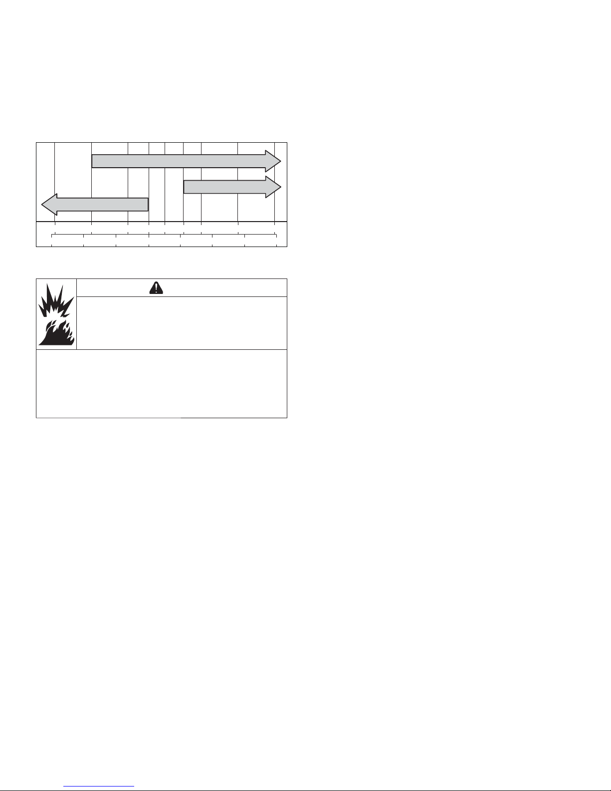
°F -20 020324060
50 80 100
°C -30 -20
-10 0 10 20 30 40
5W-30
10W-30
SAE 30
OIL RECOMMENDATIONS
We recommend use of Kohler oils for best performance.
Other high-quality detergent oils (including synthetic)
of API (American Petroleum Institute) service class SJ
or higher are acceptable. Select viscosity based on
air temperature at time of operation as shown in table
below.
FUEL RECOMMENDATIONS
WARNING
Explosive Fuel can cause fi res and severe
burns.
Do not fi ll fuel tank while engine is hot or
running.
STORAGE
If engine will be out of service for 2 months or more
follow procedure below.
1. Add Kohler PRO Series fuel treatment or equivalent
to fuel tank. Run engine 2-3 minutes to get stabilized
fuel into fuel system (failures due to untreated fuel
are not warrantable).
2. Change oil while engine is still warm from operation.
Remove spark plug(s) and pour about 1 oz. of
engine oil into cylinder(s). Replace spark plug(s) and
crank engine slowly to distribute oil.
3. Disconnect negative (–) battery cable.
4. Store engine in a clean, dry place.
Gasoline is extremely fl ammable and its vapors can
explode if ignited. Store gasoline only in approved
containers, in well ventilated, unoccupied buildings,
away from sparks or fl ames. Spilled fuel could ignite
if it comes in contact with hot parts or sparks from
ignition. Never use gasoline as a cleaning agent.
NOTE: E15, E20 and E85 are NOT approved and
should NOT be used; effects of old, stale or
contaminated fuel are not warrantable.
Fuel must meet these requirements:
● Clean, fresh, unleaded gasoline.
● Octane rating of 87 (R+M)/2 or higher.
● Research Octane Number (RON) 90 octane minimum.
● Gasoline up to 10% ethyl alcohol, 90% unleaded is
acceptable.
● Methyl Tertiary Butyl Ether (MTBE) and unleaded
gasoline blend (max 15% MTBE by volume) are
approved.
● Do not add oil to gasoline.
● Do not overfi ll fuel tank.
● Do not use gasoline older than 30 days.
4
KohlerEngines.com 32 690 03 Rev. --

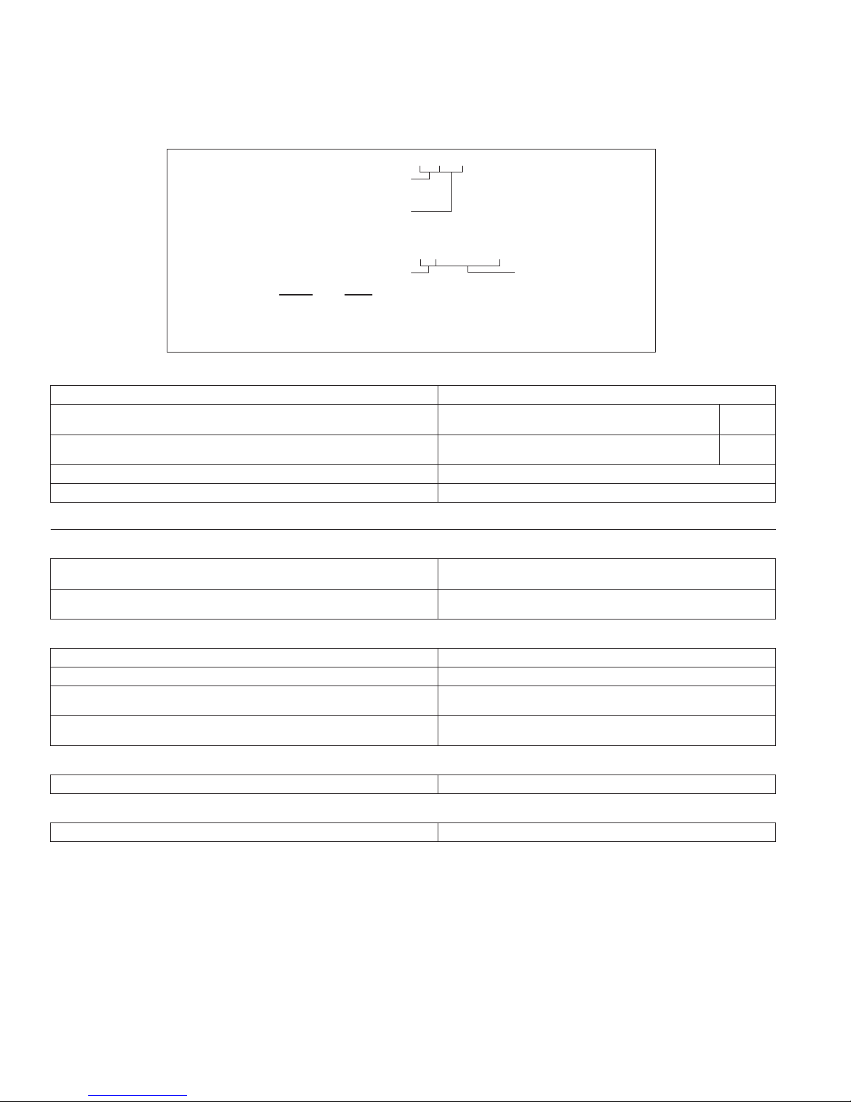
Engine Dimensions
Specifi cations
Dimensions in millimeters.
Inch equivalents shown in [ ].
32 690 03 Rev. -- KohlerEngines.com
5
Specifi cations
ENGINE IDENTIFICATION NUMBERS
Kohler engine identifi cation numbers (model, specifi cation and serial) should be referenced for effi cient repair ,
ordering correct parts, and engine replacement.
Model . . . . . . . . . . . . . . . . . . . . . KT715
7000 Series Engine
Numerical Designation
Specifi cation . . . . . . . . . . . . . . . KT715-0001
Serial . . . . . . . . . . . . . . . . . . . . .4323500328
Year Manufactured Code Factory Code
Code Year
43 2013
44 2014
45 2015
GENERAL SPECIFICATIONS
3,6
KT715 KT725 KT730 KT735 KT740 KT745
Bore 83 mm (3.27 in.)
Stroke 67 mm (2.64 in.)
Displacement 725 cc (44 cu. in.)
Oil Capacity (refi ll) 1.9 l (2.0 qt.)
Maximum Angle of Operation (@ full oil level)
TORQUE SPECIFICATIONS
3,5
4
25°
KT715 KT725 KT730 KT735 KT740 KT745
Baffl e and Sheet Metal into Aluminum
M5 Thread Forming Fasteners 8.5 N·m (75 in. lb.) into new hole
4.0 N·m (35 in. lb.) into used hole
M6 Thread Forming Fasteners 10.7 N·m (95 in. lb.) into new hole
7.3 N·m (65 in. lb.) into used hole
Blower Housing and Sheet Metal
M3 HI-LO Screw 2.3 N·m (20 in. lb.)
M4 HI-LO Screw 2.8 N·m (25 in. lb.)
M5 Fasteners 6.2 N·m (55 in. lb.) into new hole
4.0 N·m (35 in. lb.) into used hole
M6 Fasteners 10.7 N·m (95 in. lb.) into new hole
7.3 N·m (65 in. lb.) into used hole
Carburetor
Mounting Nut 6.2-7.3 N·m (55-65 in. lb.)
69 mm
(2.72 in.)
747 cc
(46 cu. in.)
Connecting Rod
Cap Fastener (torque in increments) 11.3 N·m (100 in. lb.)
3
Values are in Metric units. Values in parentheses are English equivalents.
4
Exceeding maximum angle of operation may cause engine damage from insuffi cient lubrication.
5
Lubricate threads with engine oil prior to assembly.
6
Any and all horsepower (hp) references by Kohler are Certifi ed Power Ratings and per SAE J1940 & J1995 hp
standards. Details on Certifi ed Power Ratings can be found at KohlerEngines.com.
6
KohlerEngines.com 32 690 03 Rev. --
Specifi cations
TORQUE SPECIFICATIONS
3,5
KT715 KT725 KT730 KT735 KT740 KT745
Crankcase
Breather Assembly
Outer Cover Stud
6.2 N·m (55 in. lb.) into new hole
4.0 N·m (35 in. lb.) into used hole
Outer Cover Hex Nut
1.3 N·m (11.5 in. lb.)
Oil Drain Plug 13.6 N·m (10 ft. lb.)
Cylinder Head
Head Bolt Fastener (torque in 2 increments) fi rst to 22.6 N·m (200 in. lb.)
fi nally to 41.8 N·m (370 in. lb.)
Rocker Arm Stud 11.3 N·m (100 in. lb.)
Flywheel
Retaining Screw 74.5 N·m (55 ft. lb.)
Fuel Pump
Screw 2.8 N·m (25 in. lb.)
Governor
Lever Nut 6.8 N·m (60 in. lb.)
Ignition
Spark Plug 27 N·m (20 ft. lb.)
Module Fastener 4.0-6.2 N·m (35-55 in. lb.)
Rectifi er-Regulator Fastener 4.0 N·m (35 in. lb.)
Intake Manifold
Mounting Fastener (torque in 2 increments) fi rst to 7.4 N·m (66 in. lb.)
fi nally to 9.9 N·m (88 in. lb.)
Muffl er
M8 Hex Nuts 24.4 N·m (216 in. lb.)
5/16-18 Capscrew 16.9 N·m (150 in. lb.)
Bracket Screw 9.9 N·m (88 in. lb.)
Oil Pan
Fastener 24.4 N·m (216 in. lb.)
Oil Pump
Screw (no torque sequence) 9.9 N·m (88 in. lb.)
Oil Sentry
™
Pressure Switch 4.5 N·m (40 in. lb.)
Solenoid (Starter)
Mounting Hardware 4.0-6.0 N·m (35-53 in. lb.)
Nut, Positive (+) Brush Lead 8.0-11.0 N·m (71-97 in. lb.)
Speed Control Bracket
Fastener 10.7 N·m (95 in. lb.) into new holes
7.3 N·m (65 in. lb.) into used holes
3
Values are in Metric units. Values in parentheses are English equivalents.
5
Lubricate threads with engine oil prior to assembly.
32 690 03 Rev. -- KohlerEngines.com
7

Specifi cations
TORQUE SPECIFICATIONS
3,5
KT715 KT725 KT730 KT735 KT740 KT745
Starter Assembly
Thru Bolt
Inertia Drive
Solenoid Shift
4.5-5.7 N·m (40-50 in. lb.)
5.6-9.0 N·m (49-79 in. lb.)
Mounting Screw 23.8 N·m (211 in. lb.)
Brush Holder Mounting Screw 2.5-3.3 N·m (22-29 in. lb.)
Stator
Mounting Screw 8.8 N·m (78 in. lb.)
Valve Cover
Fastener 9.6 N·m (85 in. lb.)
CLEARANCE SPECIFICATIONS
3
KT715 KT725 KT730 KT735 KT740 KT745
Camshaft
End Play 0.06/0.40 mm (0.0024/0.0157 in.)
Running Clearance 0.040/0.077 mm (0.0016/0.0030 in.)
Bore I.D.
New
Max. Wear Limit
20.000/20.025 mm (0.7874/0.7884 in.)
20.038 mm (0.7889 in.)
Bearing Surface O.D.
New
Max. Wear Limit
19.948/19.960 mm (0.7854/0.7858 in.)
19.945 mm (0.7852 in.)
Connecting Rod
Connecting Rod-to-Crankpin Running Clearance
New
Max. Wear Limit
0.037/0.083 mm (0.0015/0.0033 in.)
0.098 mm (0.0039 in.)
Connecting Rod-to-Crankpin Side Clearance 0.261/0.67 mm (0.0102/0.0264 in.)
Connecting Rod-to-Piston Pin Running Clearance 0.013/0.032 mm (0.0005/0.0013 in.)
Piston Pin End I.D.
New
Max. Wear Limit
17.013/17.027 mm (0.6698/0.6704 in.)
17.040 mm (0.6709 in.)
Crankcase
Governor Cross Shaft Bore I.D.
New
Max. Wear Limit
8.025/8.075 mm (0.3159/0.3179 in.)
8.088 mm (0.3184 in.)
3
Values are in Metric units. Values in parentheses are English equivalents.
5
Lubricate threads with engine oil prior to assembly.
8
KohlerEngines.com 32 690 03 Rev. --
Specifi cations
CLEARANCE SPECIFICATIONS
3
KT715 KT725 KT730 KT735 KT740 KT745
Crankshaft
End Play (free) 0.075/0.595 mm (0.0030/0.0023 in.)
Bore (in crankcase)
New
Max. Wear Limit
40.974/40.987 mm (1.6131/1.6137 in.)
41.000 mm (1.6142 in.)
Bore (in oil pan)
New 40.974/41.000 mm (1.6457/1.6142 in.)
Crankshaft Bore (in oil pan)-to-Crankshaft Running Clearance
New 0.039/0.087 mm (0.0015/0.0034 in.)
Flywheel End Main Bearing Journal
O.D. - New
O.D. - Max. Wear Limit
Max. Taper
Max. Out-of-Round
40.913/40.935 mm (1.6107/1.6116 in.)
40.840 mm (1.608 in.)
0.022 mm (0.0009 in.)
0.025 mm (0.0010 in.)
Oil Pan End Main Bearing Journal
O.D. - New
O.D. - Max. Wear Limit
Max. Taper
Max. Out-of-Round
40.913/40.935 mm (1.6107/1.6116 in.)
40.840 mm (1.608 in.)
0.022 mm (0.0009 in.)
0.025 mm (0.0010 in.)
Connecting Rod Journal
O.D. - New
O.D. - Max. Wear Limit
Max. Taper
Max. Out-of-Round
35.950/35.974 mm (1.4154/1.4163 in.)
35.950 mm (1.4154 in.)
0.018 mm (0.0007 in.)
0.025 mm (0.0010 in.)
T.I.R.
PTO End, Crank in Engine
Entire Crank, in V-Blocks
0.279 mm (0.0110 in.)
0.200 mm (0.0079 in.)
Cylinder Bore
Bore I.D.
New
Max. Wear Limit
Max. Out-of-Round
Max. Taper
83.006/83.031 mm (3.2679/3.2689 in.)
83.069 mm (3.2704 in.)
0.120 mm (0.0047 in.)
0.050 mm (0.0020 in.)
Cylinder Head
Max. Out-of-Flatness 0.076 mm (0.003 in.)
Governor
Governor Cross Shaft-to-Crankcase Running Clearance 0.025/0.126 mm (0.0009/0.0049 in.)
Cross Shaft O.D.
New
Max. Wear Limit
7.949/8.000 mm (0.3129/0.3149 in.)
7.936 mm (0.3124 in.)
Governor Gear Shaft-to-Governor Running Clearance 0.050/0.210 mm (0.0020/0.0083 in.)
Gear Shaft O.D.
New
Max. Wear Limit
5.990/6.000 mm (0.2358/0.2362 in.)
5.977 mm (0.2353 in.)
Ignition
Spark Plug Gap 0.76 mm (0.030 in.)
Module Air Gap 0.203/0.305 mm (0.008/0.012 in.)
3
Values are in Metric units. Values in parentheses are English equivalents.
32 690 03 Rev. -- KohlerEngines.com
9

Specifi cations
CLEARANCE SPECIFICATIONS
3
KT715 KT725 KT730 KT735 KT740 KT745
Piston, Piston Rings, and Piston Pin
Piston-to-Piston Pin Running Clearance 0.006/0.017 mm (0.0002/0.0007 in.)
Pin Bore I.D.
New
Max. Wear Limit
17.006/17.012 mm (0.6695/0.6698 in.)
17.025 mm (0.6703 in.)
Pin O.D.
New
Max. Wear Limit
16.995/17.000 mm (0.6691/0.6693 in.)
16.994 mm (0.6691 in.)
Top Compression Ring-to-Groove Side Clearance 0.030/0.070 mm (0.001/0.0026 in.)
Middle Compression Ring-to-Groove Side Clearance 0.030/0.070 mm (0.001/0.0026 in.)
Oil Control Ring-to-Groove Side Clearance 0.060/0.190 mm (0.0022/0.0073 in.)
Top Compression Ring End Gap
New Bore
Used Bore (Max.)
0.189/0.277 mm (0.0074/0.0109 in.)
0.531 mm (0.0209 in.)
Middle Compression Ring End Gap
New Bore
Used Bore (Max.)
Thrust Face O.D.
7
New
Max. Wear Limit
Piston Thrust Face-to-Cylinder Bore
7
Running Clearance
1.519/1.797 mm (0.0598/0.0708 in.)
2.051 mm (0.0808 in.)
82.978 mm (3.2668 in.)
82.833 mm (3.2611 in.)
New 0.019/0.062 mm (0.0007/0.0024 in.)
Valves and Valve Tappets
Clearance 0.127/0.178 mm (0.0050/0.0070 in.)
Valve Tappet to Crankcase Running Clearance 0.013/0.073 mm (0.0005/0.0029 in.)
Intake Valve Stem-to-Valve Guide Running Clearance 0.040/0.0780 mm (0.0016/0.0031 in.)
Exhaust Valve Stem-to-Valve Guide Running Clearance 0.052/0.090 mm (0.0020/0.0035 in.)
Intake Valve Guide I.D.
New
Max. Wear Limit
7.040/7.060 mm (0.2772/0.2780 in.)
7.140 mm (0.2811 in.)
Exhaust Valve Guide I.D.
New
Max. Wear Limit
7.040/7.060 mm (0.2772/0.2780 in.)
7.160 mm (0.2819 in.)
Valve Guide Reamer Size
Standard
0.25 mm O.S.
7.050 mm (0.2776 in.)
7.300 mm (0.2874 in.)
Intake Valve Minimum Lift 8.500 mm (0.3346 in.)
Exhaust Valve Minimum Lift 8.500 mm (0.3346 in.)
Nominal Valve Face Angle 45°
3
Values are in Metric units. Values in parentheses are English equivalents.
7
Measure 6 mm (0.2362 in.) above bottom of piston skirt at right angles to piston pin.
10
KohlerEngines.com 32 690 03 Rev. --
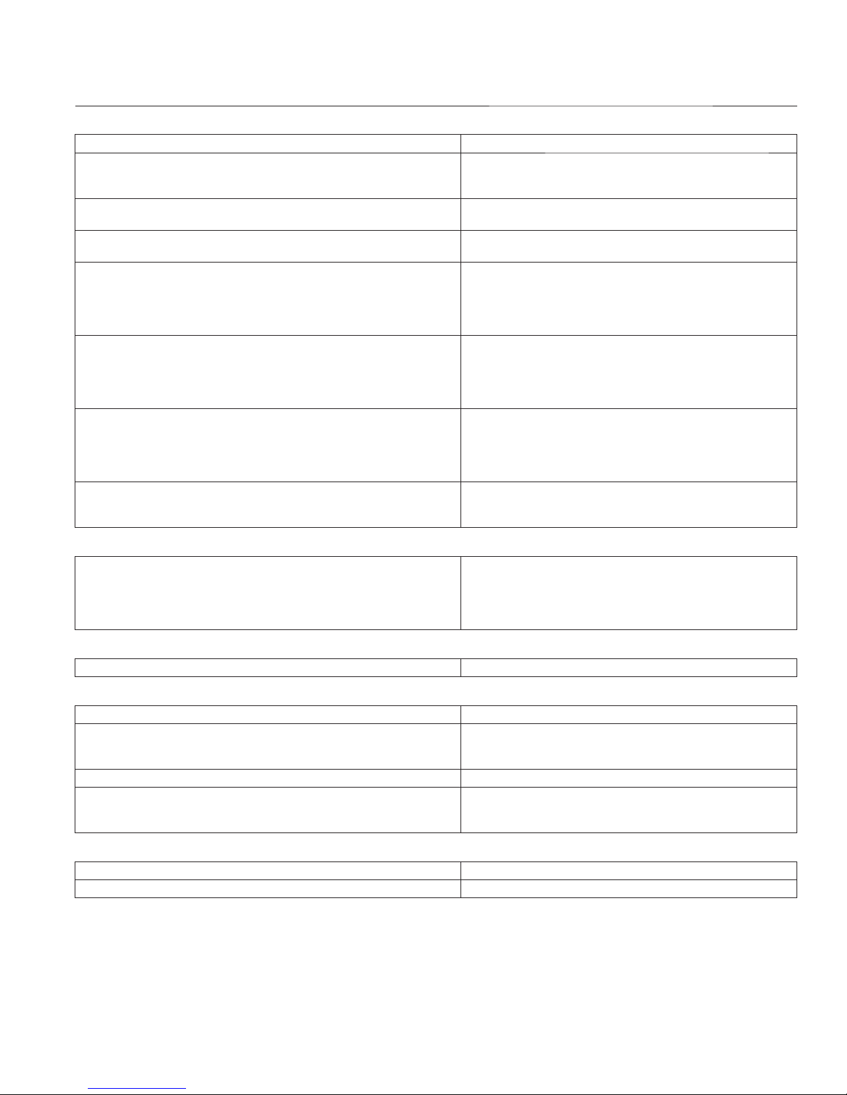
GENERAL TORQUE VALUES
English Fastener Torque Recommendations for Standard Applications
Bolts, Screws, Nuts and Fasteners Assembled Into Cast Iron or Steel
Grade 2 or 5 Fasteners
Size Grade 2 Grade 5 Grade 8
Tightening Torque: N·m (in. lb.) ± 20%
8-32 2.3 (20) 2.8 (25) — 2.3 (20)
10-24 3.6 (32) 4.5 (40) — 3.6 (32)
10-32 3.6 (32) 4.5 (40) — —
1/4-20 7.9 (70) 13.0 (115) 18.7 (165) 7.9 (70)
1/4-28 9.6 (85) 15.8 (140) 22.6 (200) —
5/16-18 17.0 (150) 28.3 (250) 39.6 (350) 17.0 (150)
5/16-24 18.7 (165) 30.5 (270) — —
3/8-16 29.4 (260) — — —
3/8-24 33.9 (300) — — —
Tightening Torque: N·m (ft. lb.) ± 20%
5/16-24 — — 40.7 (30) —
3/8-16 — 47.5 (35) 67.8 (50) —
3/8-24 — 54.2 (40) 81.4 (60) —
7/16-14 47.5 (35) 74.6 (55) 108.5 (80) —
7/16-20 61.0 (45) 101.7 (75) 142.5 (105) —
1/2-13 67.8 (50) 108.5 (80) 155.9 (115) —
1/2-20 94.9 (70) 142.4 (105) 223.7 (165) —
9/16-12 101.7 (75) 169.5 (125) 237.3 (175) —
9/16-18 135.6 (100) 223.7 (165) 311.9 (230) —
5/8-11 149.5 (110) 244.1 (180) 352.6 (260) —
5/8-18 189.8 (140) 311.9 (230) 447.5 (330) —
3/4-10 199.3 (147) 332.2 (245) 474.6 (350) —
3/4-16 271.2 (200) 440.7 (325) 637.3 (470) —
Specifi cations
Into Aluminum
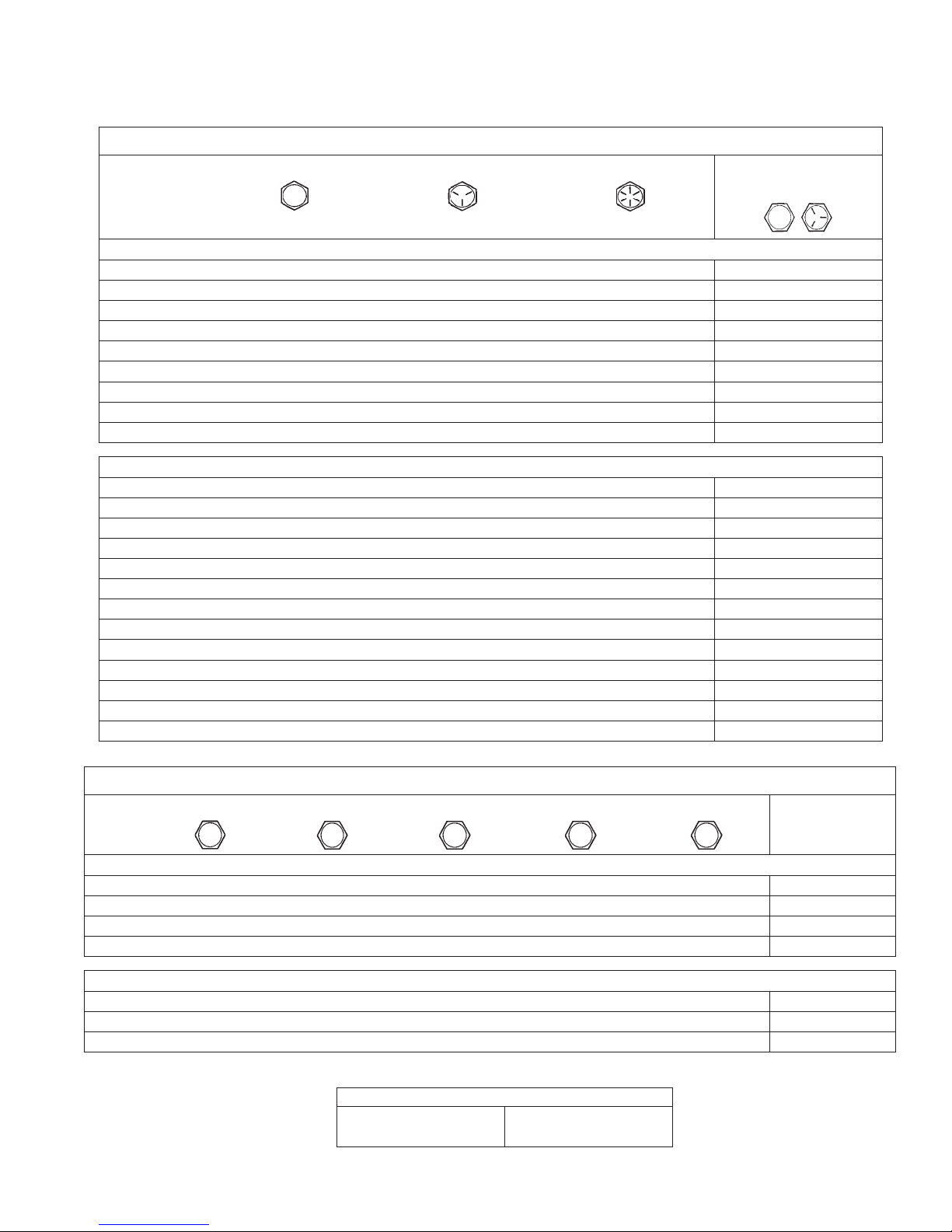
Metric Fastener Torque Recommendations for Standard Applications
Size
4.8
Tightening Torque: N·m (in. lb.) ± 10%
M4 1.2 (11) 1.7 (15) 2.9 (26) 4.1 (36) 5.0 (44) 2.0 (18)
M5 2.5 (22) 3.2 (28) 5.8 (51) 8.1 (72) 9.7 (86) 4.0 (35)
M6 4.3 (38) 5.7 (50) 9.9 (88) 14.0 (124) 16.5 (146) 6.8 (60)
M8 10.5 (93) 13.6 (120) 24.4 (216) 33.9 (300) 40.7 (360) 17.0 (150)
Tightening Torque: N·m (ft. lb.) ± 10%
M10 21.7 (16) 27.1 (20) 47.5 (35) 66.4 (49) 81.4 (60) 33.9 (25)
M12 36.6 (27) 47.5 (35) 82.7 (61) 116.6 (86) 139.7 (103) 61.0 (45)
M14 58.3 (43) 76.4 (56) 131.5 (97) 184.4 (136) 219.7 (162) 94.9 (70)
32 690 03 Rev. -- KohlerEngines.com
Property Class
5.8
8.8
10.9 12.9
Torque Conversions
N·m = in. lb. x 0.113 in. lb. = N·m x 8.85
N·m = ft. lb. x 1.356 ft. lb. = N·m x 0.737
Noncritical
Fasteners
Into Aluminum
11

Tools and Aids
Certain quality tools are designed to help you perform specifi c disassembly, repair, and reassembly procedures. By
using these tools, you can properly service engines easier, faster, and safer! In addition, you’ll increase your service
capabilities and customer satisfaction by decreasing engine downtime.
Here is a list of tools and their source.
SEPARATE TOOL SUPPLIERS
Kohler Tools
Contact your local Kohler source of
supply.
TOOLS
Description Source/Part No.
Alcohol Content Tester
For testing alcohol content (%) in reformulated/oxygenated fuels.
Camshaft Endplay Plate
For checking camshaft endplay.
Camshaft Seal Protector (Aegis)
For protecting seal during camshaft installation.
Cylinder Leakdown Tester
For checking combustion retention and if cylinder, piston, rings, or valves are worn.
Individual component available:
Adapter 12 mm x 14 mm (Required for leakdown test on XT-6 engines)
Dealer Tool Kit (Domestic)
Complete kit of Kohler required tools.
Components of 25 761 39-S
Ignition System Tester
Cylinder Leakdown Tester
Oil Pressure Test Kit
Rectifi er-Regulator Tester (120 V AC/60Hz)
Dealer Tool Kit (International)
Complete kit of Kohler required tools.
Components of 25 761 42-S
Ignition System Tester
Cylinder Leakdown Tester
Oil Pressure Test Kit
Rectifi er-Regulator Tester (240 V AC/50Hz)
Digital Vacuum/Pressure Tester
For checking crankcase vacuum.
Individual component available:
Rubber Adapter Plug
Electronic Fuel Injection (EFI) Diagnostic Software
For Laptop or Desktop PC.
EFI Service Kit
For troubleshooting and setting up an EFI engine.
Components of 24 761 01-S
Fuel Pressure Tester
Noid Light
90° Adapter
In-line "T" Fitting
Code Plug, Red Wire
Code Plug, Blue Wire
Schrader Valve Adapter Hose
Flywheel Holding Tool (CS)
For holding fl ywheel of CS series engines.
Flywheel Puller
For properly removing fl ywheel from engine.
Flywheel Strap Wrench
For holding fl ywheel during removal.
SE Tools
415 Howard St.
Lapeer, MI 48446
Phone 810-664-2981
Toll Free 800-664-2981
Fax 810-664-8181
Design Technology Inc.
768 Burr Oak Drive
Westmont, IL 60559
Phone 630-920-1300
Fax 630-920-0011
Kohler 25 455 11-S
SE Tools KLR-82405
SE Tools KLR-82417
Kohler 25 761 05-S
Design Technology Inc.
DTI-731-03
Kohler 25 761 39-S
Kohler 25 455 01-S
Kohler 25 761 05-S
Kohler 25 761 06-S
Kohler 25 761 20-S
Kohler 25 761 42-S
Kohler 25 455 01-S
Kohler 25 761 05-S
Kohler 25 761 06-S
Kohler 25 761 41-S
Design Technology Inc.
DTI-721-01
Design Technology Inc.
DTI-721-10
Kohler 25 761 23-S
Kohler 24 761 01-S
Design Technology Inc.
DTI-019
DTI-021
DTI-023
DTI-035
DTI-027
DTI-029
DTI-037
SE Tools KLR-82407
SE Tools KLR-82408
SE Tools KLR-82409
12 32 690 03 Rev. --KohlerEngines.com

Tools and Aids
TOOLS
Description Source/Part No.
Hydraulic Valve Lifter Tool
For removing and installing hydraulic lifters.
Ignition System Tester
For testing output on all systems, including CD.
Inductive Tachometer (Digital)
For checking operating speed (RPM) of an engine.
Offset Wrench (K and M Series)
For removing and reinstalling cylinder barrel retaining nuts.
Oil Pressure Test Kit
For testing/verifying oil pressure on pressure lubricated engines.
Radiator Tester
For pressure testing radiator and cap on Aegis liquid-cooled engines.
Rectifi er-Regulator Tester (120 volt current)
Rectifi er-Regulator Tester (240 volt current)
For testing rectifi er-regulators.
Components of 25 761 20-S and 25 761 41-S
CS-PRO Regulator Test Harness
Special Regulator Test Harness with Diode
Spark Advance Module (SAM) Tester
For testing SAM (ASAM and DSAM) on engines with SMART-SPARK
.
™
Starter Servicing Kit (All Starters)
For removing and reinstalling drive retaining rings and brushes.
Individual component available:
Starter Brush Holding Tool (Solenoid Shift)
Triad/OHC Timing Tool Set
For holding cam gears and crankshaft in timed position while installing timing belt.
Valve Guide Reamer (K and M Series)
For properly sizing valve guides after installation.
Valve Guide Reamer O.S. (Command Series)
For reaming worn valve guides to accept replacement oversize valves. Can be used
in low-speed drill press or with handle below for hand reaming.
Reamer Handle
For hand reaming using Kohler 25 455 12-S reamer.
Valve Guide Service Kit (Courage, Aegis, Command, OHC)
For servicing worn valve guides.
Kohler 25 761 38-S
Kohler 25 455 01-S
Design Technology Inc.
DTI-110
Kohler 52 455 04-S
Kohler 25 761 06-S
Kohler 25 455 10-S
Kohler 25 761 20-S
Kohler 25 761 41-S
Design Technology Inc.
DTI-031
DTI-033
Kohler 25 761 40-S
SE Tools KLR-82411
SE Tools KLR-82416
Kohler 28 761 01-S
Design Technology Inc.
DTI-K828
Kohler 25 455 12-S
Design Technology Inc.
DTI-K830
SE Tools KLR-82415
AIDS
Description Source/Part No.
Camshaft Lubricant (Valspar ZZ613) Kohler 25 357 14-S
Dielectric Grease (GE/Novaguard G661) Kohler 25 357 11-S
Dielectric Grease Loctite
Kohler Electric Starter Drive Lubricant (Inertia Drive) Kohler 52 357 01-S
Kohler Electric Starter Drive Lubricant (Solenoid Shift) Kohler 52 357 02-S
RTV Silicone Sealant
Loctite
®
5900® Heavy Body in 4 oz. aerosol dispenser.
Only oxime-based, oil resistant RTV sealants, such as those listed, are approved
for use. Loctite® Nos. 5900® or 5910® are recommended for best sealing
characteristics.
Spline Drive Lubricant Kohler 25 357 12-S
®
51360
Kohler 25 597 07-S
Loctite® 5910
®
Loctite® Ultra Black 598™
Loctite® Ultra Blue 587™
Loctite® Ultra Copper 5920™
1332 690 03 Rev. -- KohlerEngines.com
Tools and Aids
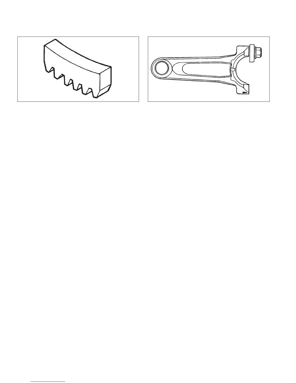
FLYWHEEL HOLDING TOOL ROCKER ARM/CRANKSHAFT TOOL
A fl ywheel holding tool can be made out of an old junk
fl ywheel ring gear and used in place of a strap wrench.
1. Using an abrasive cut-off wheel, cut out a six tooth
segment of ring gear as shown.
2. Grind off any burrs or sharp edges.
3. Invert segment and place it between ignition bosses
on crankcase so tool teeth engage fl ywheel ring
gear teeth. Bosses will lock tool and fl ywheel in
position for loosening, tightening, or removing with a
puller.
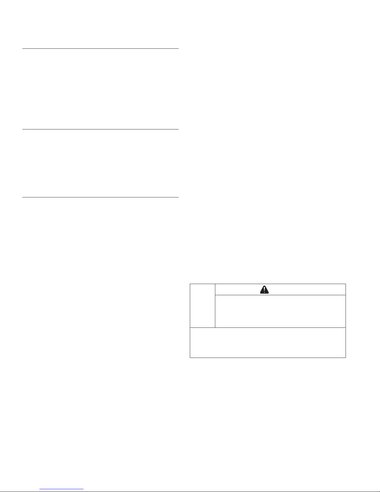
A spanner wrench to lift rocker arms or turn crankshaft
may be made out of an old junk connecting rod.
1. Find a used connecting rod from a 10 HP or larger
engine. Remove and discard rod cap.
2. Remove studs of a Posi-Lock rod or grind off
aligning steps of a Command rod, so joint surface is
fl at.
3. Find a 1 in. long capscrew with correct thread size to
match threads in connecting rod.
4. Use a fl at washer with correct I.D. to slip on
capscrew and approximately 1 in. O.D. Assemble
capscrew and washer to joint surface of rod.
14 32 690 03 Rev. --KohlerEngines.com

Troubleshooting
TROUBLESHOOTING GUIDE
When troubles occur, be sure to check simple causes which, at fi rst, may seem too obvious to be considered. For
example, a starting problem could be caused by an empty fuel tank.
Some general common causes of engine troubles are listed below and vary by engine specifi cation. Use these to
locate causing factors.
Engine Cranks But Will Not Start
● Battery connected backwards.
● Blown fuse.
● Carburetor solenoid malfunction.
● Choke not closing.
● Clogged fuel line or fuel fi lter.
● Diode in wiring harness failed in open circuit mode.
● DSAI or DSAM malfunction.
● Empty fuel tank.
● Faulty electronic control unit.
● Faulty ignition coil(s).
● Faulty spark plug(s).
● Fuel pump malfunction-vacuum hose clogged or
leaking.
● Fuel shut-off valve closed.
● Ignition module(s) faulty or improperly gapped.
● Insuffi cient voltage to electronic control unit.
● Interlock switch is engaged or faulty.
● Key switch or kill switch in OFF position.
● Low oil level.
● Quality of fuel (dirt, water, stale, mixture).
● SMART-SPARK™ malfunction.
● Spark plug lead(s) disconnected.
Engine Starts But Does Not Keep Running
● Faulty carburetor.
● Faulty cylinder head gasket.
● Faulty or misadjusted choke or throttle controls.
● Fuel pump malfunction-vacuum hose clogged or
leaking.
● Intake system leak.
● Loose wires or connections that intermittently ground
ignition kill circuit.
● Quality of fuel (dirt, water, stale, mixture).
● Restricted fuel tank cap vent.
Engine Starts Hard
● Clogged fuel line or fuel fi lter.
● Engine overheated.
● Faulty ACR mechanism.
● Faulty or misadjusted choke or throttle controls.
● Faulty spark plug(s).
● Flywheel key sheared.
● Fuel pump malfunction-vacuum hose clogged or
leaking.
● Interlock switch is engaged or faulty.
● Loose wires or connections that intermittently ground
ignition kill circuit.
● Low compression.
● Quality of fuel (dirt, water, stale, mixture).
● Weak spark.
Engine Will Not Crank
● Battery is discharged.
● Faulty electric starter or solenoid.
● Faulty key switch or ignition switch.
● Interlock switch is engaged or faulty.
● Loose wires or connections that intermittently ground
ignition kill circuit.
● Pawls not engaging in drive cup.
● Seized internal engine components.
Engine Runs But Misses
● Carburetor adjusted incorrectly.
● Engine overheated.
● Faulty spark plug(s).
● Ignition module(s) faulty or improperly gapped.
● Incorrect crankshaft position sensor air gap.
● Interlock switch is engaged or faulty.
● Loose wires or connections that intermittently ground
ignition kill circuit.
● Quality of fuel (dirt, water, stale, mixture).
● Spark plug lead(s) disconnected.
● Spark plug lead boot loose on plug.
● Spark plug lead loose.
Engine Will Not Idle
● Engine overheated.
● Faulty spark plug(s).
● Idle fuel adjusting needle(s) improperly set.
● Idle speed adjusting screw improperly set.
● Inadequate fuel supply.
● Low compression.
● Quality of fuel (dirt, water, stale, mixture).
● Restricted fuel tank cap vent.
Engine Overheats
● Cooling fan broken.
● Excessive engine load.
● Fan belt failed/off.
● Faulty carburetor.
● High crankcase oil level.
● Lean fuel mixture.
● Low cooling system fl uid level.
● Low crankcase oil level.
● Radiator, and/or cooling system components clogged,
restricted, or leaking.
● Water pump belt failed/broken.
● Water pump malfunction.
Engine Knocks
● Excessive engine load.
● Hydraulic lifter malfunction.
● Incorrect oil viscosity/type.
● Internal wear or damage.
● Low crankcase oil level.
● Quality of fuel (dirt, water, stale, mixture).
1532 690 03 Rev. -- KohlerEngines.com
Troubleshooting
Engine Loses Power
● Dirty air cleaner element.
● Engine overheated.
● Excessive engine load.
● Restricted exhaust.
● Faulty spark plug(s).
● High crankcase oil level.
● Incorrect governor setting.
● Low battery.
● Low compression.
● Low crankcase oil level.
● Quality of fuel (dirt, water, stale, mixture).
Engine Uses Excessive Amount of Oil
● Loose or improperly torqued fasteners.
● Blown head gasket/overheated.
● Breather reed broken.
● Clogged, broken, or inoperative crankcase breather.
● Crankcase overfi lled.
● Incorrect oil viscosity/type.
● Worn cylinder bore.
● Worn or broken piston rings.
● Worn valve stems/valve guides.
Oil Leaks from Oil Seals, Gaskets
● Breather reed broken.
● Clogged, broken, or inoperative crankcase breather.
● Loose or improperly torqued fasteners.
● Piston blow by, or leaky valves.
● Restricted exhaust.
EXTERNAL ENGINE INSPECTION
NOTE: It is good practice to drain oil at a location away
from workbench. Be sure to allow ample time for
complete drainage.
Before cleaning or disassembling engine, make a
thorough inspection of its external appearance and
condition. This inspection can give clues to what
might be found inside engines (and cause) when it is
disassembled.
● Check for buildup of dirt and debris on crankcase,
cooling fi ns, grass screen, and other external surfaces.
Dirt or debris on these areas can cause overheating.
● Check for obvious fuel and oil leaks, and damaged
components. Excessive oil leakage can indicate a
clogged or inoperative breather, worn or damaged
seals or gaskets, or loose fasteners.
● Check air cleaner cover and base for damage or
indications of improper fi t and seal.
● Check air cleaner element. Look for holes, tears,
cracked or damaged sealing surfaces, or other
damage that could allow unfi ltered air into engine. A
dirty or clogged element could indicate insuffi cient or
improper maintenance.
● Check carburetor throat for dirt. Dirt in throat is further
indication that air cleaner was not functioning properly.
● Check if oil level is within operating range on dipstick.
If it is above, sniff for gasoline odor.
● Check condition of oil. Drain oil into a container; it
should fl ow freely. Check for metal chips and other
foreign particles.
Sludge is a natural by-product of combustion; a small
accumulation is normal. Excessive sludge formation
could indicate over rich fuel settings, weak ignition,
overextended oil change interval or wrong weight or
type of oil was used.
CLEANING ENGINE
WARNING
Cleaning Solvents can cause severe injury or
death.
Use only in well ventilated areas away from
ignition sources.
Carburetor cleaners and solvents are extremely
fl ammable. Follow cleaner manufacturer’s warnings
and instructions on its proper and safe use. Never use
gasoline as a cleaning agent.
After inspecting external condition of engine, clean
engine thoroughly before disassembly. Clean individual
components as engine is disassembled. Only clean
parts can be accurately inspected and gauged for wear
or damage. There are many commercially available
cleaners that will quickly remove grease, oil, and grime
from engine parts. When such a cleaner is used, follow
manufacturer’s instructions and safety precautions
carefully.
Make sure all traces of cleaner are removed before
engine is reassembled and placed into operation. Even
small amounts of these cleaners can quickly break down
lubricating properties of engine oil.
16 32 690 03 Rev. --KohlerEngines.com
CRANKCASE VACUUM TEST
Troubleshooting
WARNING
Carbon Monoxide can cause severe nausea,
fainting or death.
Avoid inhaling exhaust fumes.
Engine exhaust gases contain poisonous carbon
monoxide. Carbon monoxide is odorless, colorless,
and can cause death if inhaled.
A partial vacuum should be present in crankcase when engine is operating. Pressure in crankcase (normally caused
by a clogged or improperly assembled breather) can cause oil to be forced out at oil seals, gaskets, or other available
spots.
Crankcase vacuum is best measured with either a water manometer or a vacuum gauge. Complete instructions are
provided in kits.
To test crankcase vacuum with manometer:
1. Insert rubber stopper into oil fi ll hole. Be sure pinch
clamp is installed on hose and use tapered adapters
to connect hose between stopper and one
manometer tube. Leave other tube open to
atmosphere. Check that water level in manometer is
at 0 line. Make sure pinch clamp is closed.
2. Start engine and run no-load high speed.
3. Open clamp and note water level in tube.
Level in engine side should be a minimum of
10.2 cm (4 in.) above level in open side.
If level in engine side is less than specifi ed (low/no
vacuum), or level in engine side is lower than level in
open side (pressure), check for conditions in table
below.
4. Close pinch clamp before stopping engine.
Keep hands, feet, hair, and clothing away from all
moving parts to prevent injury. Never operate engine
with covers, shrouds, or guards removed.
To test crankcase vacuum with vacuum/pressure gauge:
1. Remove dipstick or oil fi ll plug/cap.
2. Install adapter into oil fi ll/dipstick tube opening,
3. Run engine and observe gauge reading.
Analog tester–needle movement to left of 0 is a
Digital tester–depress test button on top of tester.
Crankcase vacuum should be a minimum of 10.2 cm
Rotating Parts can cause severe injury.
Stay away while engine is in operation.
upside down over end of a small diameter dipstick
tube, or directly into engine if a tube is not used.
Insert barbed gauge fi tting into hole in stopper.
vacuum, and movement to right indicates a
pressure.
(4 in.) of water. If reading is below specifi cation, or if
pressure is present, check table below for possible
causes and conclusions.
WARNING
Condition Conclusion
Crankcase breather clogged or inoperative. NOTE: If breather is integral part of valve cover and
cannot be serviced separately, replace valve
cover and recheck pressure.
Disassemble breather, clean parts thoroughly, check
sealing surfaces for fl atness, reassemble, and recheck
pressure.
Seals and/or gaskets leaking. Loose or improperly torque
fasteners.
Piston blow by or leaky valves (confi rm by inspecting
components).
Restricted exhaust. Check exhaust screen/spark arrestor (if equipped). Clean
Replace all worn or damaged seals and gaskets. Make
sure all fasteners are tightened securely. Use appropriate
torque valves and sequences when necessary.
Recondition piston, rings, cylinder bore, valves and
valves guides.
or replace as needed. Repair or replace any other
damaged/restricted muffl er or exhaust system parts.
1732 690 03 Rev. -- KohlerEngines.com

Troubleshooting
COMPRESSION TEST
For Command Twins:
A compression test is best performed on a warm engine. Clean any dirt or debris away from base of spark plug(s)
before removing them. Be sure choke is off, and throttle is wide open during test. Compression should be at least
160 psi and should not vary more than 15% between cylinders.
All other models:
These engines are equipped with an automatic compression release (ACR) mechanism. It is diffi cult to obtain an
accurate compression reading because of ACR mechanism. As an alternative, use cylinder leakdown test described
below.
CYLINDER LEAKDOWN TEST
A cylinder leakdown test can be a valuable alternative to a compression test. By pressurizing combustion chamber
from an external air source you can determine if valves or rings are leaking, and how badly.
Cylinder leakdown tester is a relatively simple, inexpensive leakdown tester for small engines. This tester includes a
quick-connect for attaching adapter hose and a holding tool.
1. Run engine for 3-5 minutes to warm it up.
2. Remove spark plug(s) and air fi lter from engine.
3. Rotate crankshaft until piston (of cylinder being tested) is at top dead center (TDC) of compression stroke. Hold
engine in this position while testing. Holding tool supplied with tester can be used if PTO end of crankshaft is
accessible. Lock holding tool onto crankshaft. Install a 3/8 in. breaker bar into hole/slot of holding tool, so it is
perpendicular to both holding tool and crankshaft PTO.
If fl ywheel end is more accessible, use a breaker bar and socket on fl ywheel nut/screw to hold it in position. An
assistant may be needed to hold breaker bar during testing. If engine is mounted in a piece of equipment, it may
be possible to hold it by clamping or wedging a driven component. Just be certain that engine cannot rotate off of
TDC in either direction.
4. Install adapter into spark plug hole, but do not attach it to tester at this time.
5. Turn regulator knob completely counterclockwise.
6. Connect an air source of at least 50 psi to tester.
7. Turn regulator knob clockwise (increase direction) until gauge needle is in yellow set area at low end of scale.
8. Connect tester quick-connect to adapter hose. While fi rmly holding engine at TDC, gradually open tester valve.
Note gauge reading and listen for escaping air at combustion air intake, exhaust outlet, and crankcase breather.
Condition Conclusion
Air escaping from crankcase breather. Ring or cylinder worn.
Air escaping from exhaust system. Defective exhaust valve/improper seating.
Air escaping from intake. Defective intake valve/improper seating.
Gauge reading in low (green) zone. Piston rings and cylinder in good condition.
Gauge reading in moderate (yellow) zone. Engine is still usable, but there is some wear present.
Customer should start planning for overhaul or
replacement.
Gauge reading in high (red) zone. Rings and/or cylinder have considerable wear. Engine
should be reconditioned or replaced.
18 32 690 03 Rev. --KohlerEngines.com
Air Cleaner/Intake
AIR CLEANER
These systems are CARB/EPA certifi ed and components
should not be altered or modifi ed in any way.
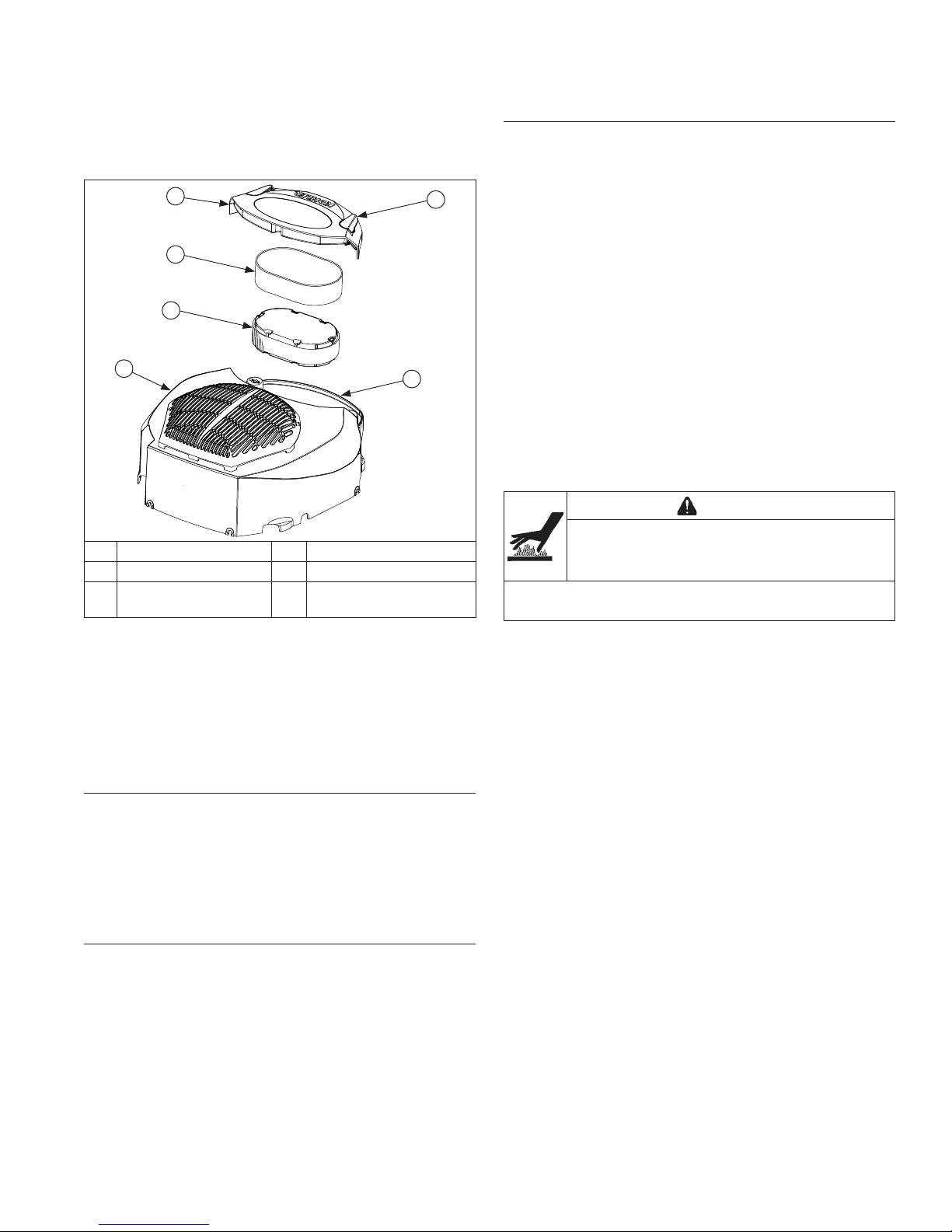
Air Cleaner Components
C
A
B
D
A Precleaner B Paper Element
C Air Cleaner Cover D Blower Housing
E
NOTE: Operating engine with loose or damaged air
NOTE: Paper element cannot be blown out with
Rotate air cleaner cover levers outward to unlock cover;
remove air cleaner cover.
Air Cleaner
Cover Lever
cleaner components could cause premature
wear and failure. Replace all bent or damaged
components.
compressed air.
F Air Cleaner Base
E
F
Air Cleaner Base
Disassembly/Reassembly
If air cleaner base requires removal, proceed as follows:
1. Remove mounting screws for fuel pump (if
equipped), and blower housing.
2. Raise or remove blower housing for access to air
cleaner base.
3. Remove air cleaner components from base.
4. Remove nuts securing air cleaner base onto
mounting studs.
5. Disconnect breather hose from air cleaner base,
then remove base and gasket.
6. Reverse procedure to reassemble components.
Torque nuts to 6.2-7.3 N·m (55-65 in. lb.). Torque
blower housing screws to 4.0 N·m (35 in. lb.), and
front HI-LO screws to 2.8 N·m (25 in. lb.).
BREATHER TUBE
Ensure both ends of breather tube are properly
connected.
AIR COOLING
WARNING
Hot Parts can cause severe burns.
Do not touch engine while operating or just
after stopping.
Never operate engine with heat shields or guards
removed.
Proper cooling is essential. To prevent over heating,
clean screens, cooling fi ns, and other external surfaces
of engine. Avoid spraying water at wiring harness or any
electrical components. Refer to Maintenance Schedule.
Precleaner (if equipped)
1. Remove precleaner from paper element.
2. Replace or wash precleaner in warm water with
detergent. Rinse and allow to air dry.
3. Lightly oil precleaner with new engine oil; squeeze
out excess oil.
4. Reinstall precleaner over paper element.
Paper Element
1. Remove element from base; service precleaner.
Discard element.
2. Install precleaner over new paper element and install
on base.
Position air cleaner cover with levers outward over air
cleaner; turn levers inward to lock.
32 690 03 Rev. -- KohlerEngines.com
19

Fuel System
Typical carbureted fuel system and related components
include:
● Fuel tank.
● Fuel lines.
● In-line fuel fi lter.
● Fuel pump.
● Carburetor.
Fuel from tank is moved through in-line fi lter and fuel
lines by fuel pump. Fuel then enters carburetor fl oat bowl
and is drawn into carburetor body and mixed with air.
This fuel-air mixture is then burned in engine combustion
chamber.
FUEL RECOMMENDATIONS
Refer to Maintenance.
FUEL LINE
Low permeation fuel line must be installed on carbureted
Kohler Co. engines to maintain EPA and CARB
regulatory compliance.
FUEL PUMP
Some engines use a pulse style fuel pump. Pumping
action of pulse style pumps is created by oscillation of
positive and negative pressures within crankcase. This
pressure is transmitted to pulse pump through rubber
hose connected between pump and crankcase. Pumping
action causes diaphragm on inside of pump to pull fuel
in on its downward stroke and to push it into carburetor
on its upward stroke. Two check valves prevent fuel from
going backward through pump.
Performance
Minimum fuel delivery rate must be 7.5 l/hr. (2 gal./hr.)
with a pressure at 0.3 psi and a fuel lift of 24 in. A
1.3 l/hr. (0.34 gal./hr.) fuel rate must be maintained at
5 Hz.
Fuel Pump Replacement
NOTE: Make sure orientation of new pump is consistent
with removed pump. Internal damage may occur
if installed incorrectly.
To replace pulse pump follow these steps. Note
orientation of pump before removing.
1. Disconnect fuel lines from inlet, outlet, and pulse
fi ttings on fuel pump.
2. Remove screws and take off pump.
3. Connect pulse line to new fuel pump and make sure
opposite end is properly connected into valve cover.
4. Attach new fuel pump using screws. Torque screws
to 2.8 N·m (25 in. lb.).
5. Reconnect fuel lines to inlet and outlet fi ttings and
secure with clamps.
FUEL SYSTEM TESTS
When engine starts hard or turns over but will not start, fuel system might be causing problems. Test fuel system by
performing following test.
1. Check for fuel in combustion chamber.
a. Disconnect and ground spark plug leads.
b. Close choke on carburetor.
c. Crank engine several times.
d. Remove spark plug and check for fuel at tip.
2. Check for fuel fl ow from tank to fuel pump.
a. Remove fuel line from inlet fi tting of fuel pump.
b. Hold line below bottom of tank. Open shut-off
valve (if equipped) and observe fl ow.
Condition Conclusion
Fuel at tip of spark plug. Fuel is reaching combustion chamber.
No fuel at tip of spark plug. Check fuel fl ow from fuel tank (step 2).
Fuel fl ows from fuel line. Check for faulty fuel pump (step 3).
No fuel fl ow from fuel line. Check fuel tank cap vent, fuel pickup screen, in-line
Fuel line condition. Check for a clogged fuel line. If fuel line is unobstructed,
3. Check operation of fuel pump.
a. Remove fuel line from inlet fi tting of carburetor.
b. Crank engine several times and observe fl ow .
If fuel pump is working, check for faulty carburetor. Refer
to Carburetor.
fi lter, shut-off valve, and fuel line. Correct any observed
problem and reconnect line.
check for overfi lled crankcase and/or oil in pulse line. If
checks don't reveal cause of problem, replace pump.
20 32 690 03 Rev. --KohlerEngines.com
Fuel System
CARBURETOR
WARNING
Explosive Fuel can cause fi res and severe
burns.
Do not fi ll fuel tank while engine is hot or
running.
Gasoline is extremely fl ammable and its vapors can
explode if ignited. Store gasoline only in approved
containers, in well ventilated, unoccupied buildings,
away from sparks or fl ames. Spilled fuel could ignite
if it comes in contact with hot parts or sparks from
ignition. Never use gasoline as a cleaning agent.
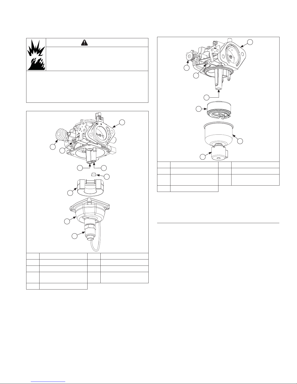
Keihin One-Barrel Carburetor Components
B
I
A
E
F
C
D
Walbro One-Barrel Carburetor Components
B
G
A
C
D
E
F
A Idle Speed Screw B Carburetor Body
C Main Jet D Float
E Fuel Bowl F
G Choke Lever
Engines in this series are equipped with either a Keihin
or Walbro fi xed main jet carburetor. Most carburetors
utilize a fuel shut-off solenoid and feature a self-relieving
choke.
Shut-off Solenoid
Assembly
H
G
A Idle Speed Screw B Carburetor Body
C Idle Jet D Plug
E Main Jet F Float
Shut-off Solenoid
G
I Choke Lever
Assembly
H Fuel Bowl
Troubleshooting Checklist
When engine starts hard, runs rough, or stalls at low
idle speed, check these areas before adjusting or
disassembling carburetor.
1. Make sure fuel tank is fi lled with clean, fresh
gasoline.
2. Make sure fuel tank cap vent is not blocked and is
operating properly.
3. Make sure fuel is reaching carburetor. This includes
checking fuel shut-off valve, fuel tank fi lter screen,
in-line fuel fi lter, fuel lines and fuel pump for
restrictions or faulty components as necessary.
4. Make sure air cleaner base and carburetor are
securely fastened to engine using gaskets in good
condition.
5. Make sure air cleaner element (including precleaner
if equipped) is clean and all air cleaner components
are fastened securely.
6. Make sure ignition system, governor system,
exhaust system, and throttle and choke controls are
operating properly.
2132 690 03 Rev. -- KohlerEngines.com
 Loading...