

Page 1

Installation Guide
Transfer Valve
K-728
M product numbers are for Mexico (i.e. K-12345M)
Los números de productos seguidos de
M corresponden a México (Ej.
K-12345M)
Français, page “Français-1”
Español, página “Español-1”
1145567-2-C
Page 2
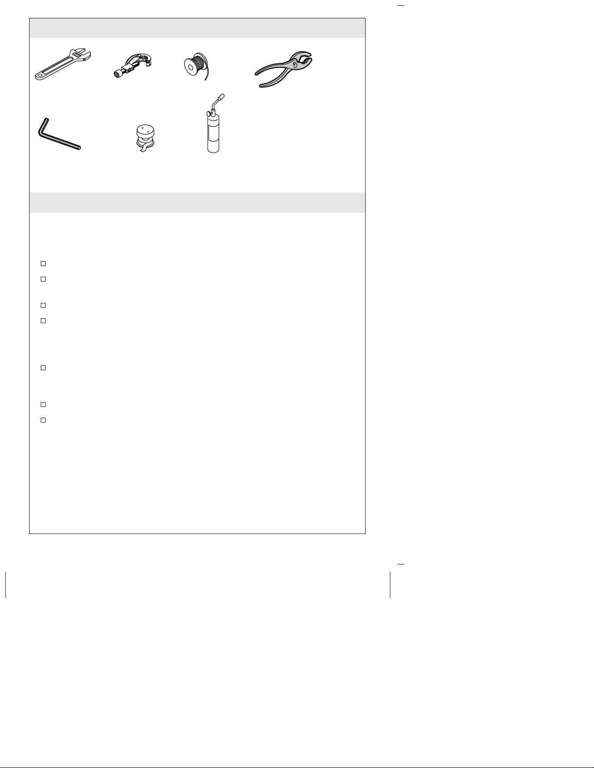
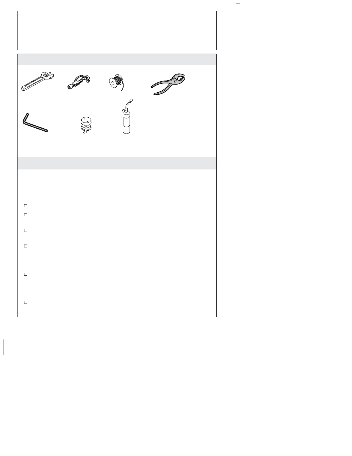
Tools and Materials
1/4"
Hex Wrench
Tubing Cutter Solder
Thread
Sealant
Propane
Torch
Plus:
• 1/2" Piping or Copper
Tubing for outlets
• 3/4" Piping or Copper
Tubing for inlets
• 1/2" NPT Plug
Before You Begin
IMPORTANT! Risk of product damage. Do not apply direct heat
to the transfer valve body. Excessive heat will damage the plastic
valve components and plaster guard.
Observe all local plumbing and building codes.
Do not remove the plaster guard from the transfer valve until
instructed to do so.
A mixed water supply is required for this transfer valve.
If less than three accessories will be installed, do not plug any
outlets on this transfer valve without completing the two-way
conversion. The transfer valve is not intended to be used as a
shut-off valve.
Carefully plan the installation before beginning. Carefully read
the entire instructions. Component location, spacing, and
situational requirements can vary.
Shut off the main water supply.
Inspect the waste and supply tubing; replace if necessary.
1145567-2-C 2 Kohler Co.
Page 3
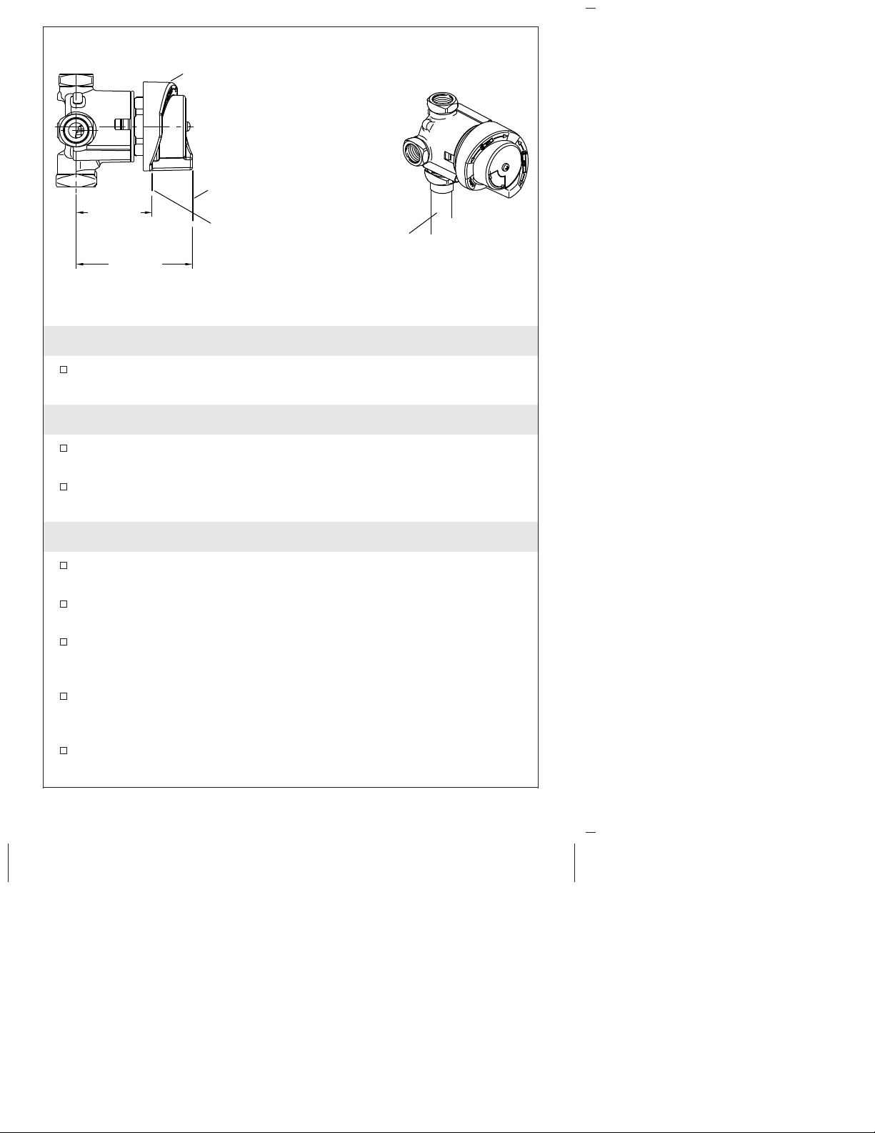
Plaster
Guard
Max
Finished
2-7/16"
(62 mm)
3-3/4"
(95 mm)
Wall
Min
Finished
Wall
Mixed Water
Supply 3/4"
Copper Tubing
or Piping
1. Prepare the Site
Provide a 2-7/8″ (73 mm) to 3-1/8″ (79 mm) diameter hole in the
wall material for the plaster guard.
2. For All Installations
Route the 3/4″ mixed water supply line to the transfer valve
location.
Apply thread sealant to the inlet port threads and connect the
water supply to the transfer valve inlet.
3. Three-Way Valve Installation
Install 1/2″ copper tubing or 1/2″ piping for all accessories.
Securely fasten the piping and outlet ells to the framing.
Install temporary 1/2″ nipples in the outlet ells so they extend a
minimum of 2″ (51 mm) beyond the finished wall.
Turn on the water supply to the transfer valve and check the
transfer valve for proper operation and leakage. Once everything
is verified, turn off the water.
Install caps on the temporary bath and shower nipples. Turn on
the water and check for leaks. Once no leakage is verified, turn
off the water.
Complete the finished wall.
Kohler Co. 3 1145567-2-C
Page 4
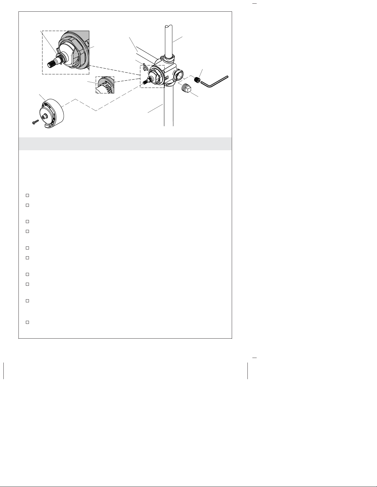
E-Ring
Missing Tooth
Plaster Guard
Accessory # 2
Water Line
Detent
Spacer
Mixed Water Supply 3/4"
Copper Tubing or Piping
Accessory # 1
Water Line
Plug
1/2"
NPT Plug
4. Two-Way Valve Installation
Convert to a Two-Way Valve
IMPORTANT! If less than three accessories will be installed, do not
plug any outlets on this transfer valve without completing the
two-way conversion. The transfer valve is not intended to be used
as a shut-off valve.
Temporarily remove the plaster guard.
Rotate the detent until positioned vertically; see above
illustration.
Verify the missing tooth is oriented up.
Identify the plug at the center of the valve body and the spacer
underneath the detent.
Using a hex wrench, remove the plug. Discard the plug.
Plug the port that will not be used (either the left or right port)
with a 1/2″ NPT plug (not included).
Use pliers to remove the spacer from beneath the detent.
Push the detent down; ensure the points of the detent engage the
notches of the valve cartridge.
Install the spacer above the detent and under the E-ring.
Install the Two-Way Valve
Install 1/2″ copper tubing or 1/2″ piping for both accessories.
Securely fasten the piping and outlet ells to the framing.
1145567-2-C 4 Kohler Co.
Page 5
Two-Way Valve Installation (cont.)
Install temporary 1/2″ nipples in the outlet ells so they extend a
minimum of 2″ (51 mm) beyond the planned finished wall.
IMPORTANT! When testing the valve operation, your selections
should be as follows: Accessory 1, Accessories 1 and 2, Accessory 2.
If your valve operates as follows: Accessory 2, Accessory 2,
Accessories 1 and 2; you will need to remove the spacer, rotate the
detent 180 degrees; then reinstall the spacer.
Turn on the water supply to the transfer valve and check the
transfer valve for proper operation and leakage. Once everything
is verified, turn off the water.
Install caps on the temporary bath and shower nipples. Turn on
the water and check for leaks. Once no leakage is verified, turn
off the water.
Reinstall the plaster guard.
Complete the finished wall.
Remove and discard the plaster guard.
Install the trim according to the installation instructions packed
with the trim.
Kohler Co. 5 1145567-2-C
Page 6
Guide d’installation
Robinet coupleur
Outils et matériaux
Coupe-tuyauterie Soudure
Plus:
• Tuyauterie ou tubage en
1/4"
Clé hexagonale
Joint d'étanchéité
pour filetage
Chalumeau
à propane
Avant de commencer
IMPORTANT! Risque d’endommagement du produit. Ne pas
appliquer de chaleur directe sur le corps du robinet coupleur. Une
chaleur excessive endommagera les composants en plastique du
robinet ainsi que le protecteur de plâtre.
cuivre de 1/2" pour sorties
• Tuyauterie ou tubage en
cuivre de 3/4" pour entrées
• Bouchon NTP 1/2"
Respecter tous les codes de plomberie et de bâtiment locaux.
Ne pas retirer le protecteur de plâtre du robinet coupleur avant
d’obtenir des instructions spécifiques.
Une alimentation d’eau mélangée est nécessaire pour ce robinet
coupleur.
Si moins de trois accessoires seront installés, ne pas brancher de
prises sur ce robinet coupleur sans terminer la conversion à deux
voies. Le robinet coupleur n’est pas destiné à être utilisé en tant
que robinet d’arrêt.
Planifier soigneusement l’installation avant de commencer. Lire
avec attention les instructions dans leur intégralité.
L’emplacement des composants, l’espacement et les exigences
selon les circonstances peuvent varier.
Couper l’alimentation en eau principale.
Kohler Co. Français-1 1145567-2-C
Page 7

Avant de commencer (cont.)
Inspecter l’état des tubes d’évacuation et d’alimentation;
remplacer si nécessaire.
Kohler Co. Français-2 1145567-2-C
Page 8

Renfort en
plâtre
Mur fini
max.
2-7/16"
(62 mm)
3-3/4"
(95 mm)
Mur fini
min.
Tuyauterie ou
tubage d'alimentation
en cuivre de 3/4"
d'eau mélangée.
1. Préparer le site
Prévoir un orifice d’un diamètre compris entre 2-7/8″ (73 mm) et
3-1/8″ (79 mm) dans le matériau du mur pour le protecteur de
plâtre.
2. Pour toutes les installations
Acheminer la conduite d’alimentation en eau mélangée de 3/4″
vers l’emplacement du robinet coupleur.
Appliquer un ruban d’étanchéité pour joints filetés sur les filets
du port d’entrée puis raccorder le tuyau d’alimentation en eau à
l’entrée du robinet coupleur.
3. Installation du robinet à trois voies
Installer le tube en cuivre de 1/2″ ou le tuyau de 1/2″ pour tous
les accessoires. Sécuriser la tuyauterie et les coudes de sortie au
cadrage.
Installer des mamelons temporaires de 1/2″ dans les coudes de
sortie de manière à ce qu’ils s’étendent de 2″ (51 mm) au-delà du
mur fini.
Ouvrir l’alimentation en eau au robinet coupleur, puis vérifier le
bon fonctionnement de celui-ci et s’assurer de l’absence de fuites.
Après vérification, couper l’eau.
1145567-2-C Français-3 Kohler Co.
Page 9

Installation du robinet à trois voies (cont.)
Installer des capuchons sur les mamelons temporaires de la
baignoire et de la douche. Faire couler l’eau et rechercher des
fuites. Si aucune fuite n’a été détectée, couper l’eau.
Terminer le mur fini.
Kohler Co. Français-4 1145567-2-C
Page 10

Anneau-E
Détente
Dent manquante
Renfort en plâtre
Tuyauterie ou tubage d'alimentation
en cuivre de 3/4" d'eau mélangée.
Ligne d'eau
accessoire # 2
Espaceur
Ligne d'eau
accessoire # 1
Bouchon
Bouchon
NTP 1/2"
4. Installation du robinet à deux voies
Convertir en robinet à deux voies
IMPORTANT! Si moins de trois accessoires seront installés, ne pas
brancher de prises sur ce robinet coupleur sans terminer la
conversion à deux voies. Le robinet coupleur n’est pas destiné à être
utilisé en tant que robinet d’arrêt.
Retirer temporairement le protecteur de plâtre.
Tourner le cran jusqu’à ce qu’il soit positionné verticalement; voir
l’illustration ci-dessus.
Vérifier que la dent manquante est orientée vers le haut.
Identifier le bouchon au centre du corps du robinet ainsi que
l’espaceur sous le cran.
Utiliser une clé six pans pour retirer le bouchon. Jeter le bouchon.
Boucher le port qui ne sera pas utilisé (le droit ou le gauche) avec
un bouchon NPT de 1/2″ (non inclus).
Utiliser des pinces pour retirer l’espaceur qui se trouve sous le
cran.
Pousser le cran vers le bas; s’assurer que les dents du cran
s’enclenchent sur les encoches de la cartouche du robinet.
Installer l’espaceur au-dessus du cran et sous l’anneau en E.
Installer le robinet à deux voies
1145567-2-C Français-5 Kohler Co.
Page 11

Installation du robinet à deux voies (cont.)
Installer le tube en cuivre de 1/2″ ou le tuyau de 1/2″ pour les
deux accessoires. Sécuriser la tuyauterie et les coudes de sortie au
cadrage.
Installer des mamelons temporaires de 1/2″ dans les coudes de
sortie de manière à ce qu’ils s’étendent de 2″ (51 mm) au-delà du
mur fini prévu.
IMPORTANT! Lors du test du fonctionnement du robinet, les
sélections doivent être les suivantes : Accessoire 1, Accessoires 1 et 2,
Accessoire 2. Si le robinet fonctionne comme suit: Accessoire 2,
Accessoire 2, Accessoires 1 et 2; l’espaceur doit être retiré, le cran
doit être tourné de 180 degrés; l’espaceur doit être réinstallé.
Ouvrir l’alimentation en eau au robinet coupleur, puis vérifier le
bon fonctionnement de celui-ci et s’assurer de l’absence de fuites.
Après vérification, couper l’eau.
Installer des capuchons sur les mamelons temporaires de la
baignoire et de la douche. Faire couler l’eau et rechercher des
fuites. Si aucune fuite n’a été détectée, couper l’eau.
Réinstaller le protecteur de plâtre.
Terminer le mur fini.
Retirer et jeter le protecteur de plâtre.
Installer la garniture en suivant les instructions d’installation
accompagnant celle-ci.
Kohler Co. Français-6 1145567-2-C
Page 12

Guía de instalación
Válvula de transferencia
Herramientas y materiales
Cortatubos Suelda
Más:
1/4"
Llave hexagonal
Cinta selladora
de roscas
Soplete de
propano
Antes de comenzar
¡IMPORTANTE! Riesgo de daños al producto. No aplique calor
directo al cuerpo de la válvula de transferencia. El calor excesivo
puede dañar los componentes plásticos de la válvula y el protector
de yeso.
• Tubería o tubos de cobre
de 1/2" para las salidas
• Tubería o tubos de cobre
de 3/4" para las entradas
• Tapón de 1/2" NPT
Cumpla con todos los códigos locales de plomería y construcción.
No quite los protectores de yeso de la válvula de transferencia
hasta que se le indique.
Esta válvula de transferencia requiere un suministro mixto de
agua.
Si va a instalar menos de tres accesorios, no tape ninguna de las
salidas de esta válvula de transferencia sin terminar la conversión
de dos vías. Esta válvula de transferencia no está diseñada para
utilizarse como llave de paso.
Planifique detenidamente la instalación, antes de comenzar. Lea
atentamente todas las instrucciones. El lugar de instalación de los
componentes, la distancia de separación entre ellos y los
requisitos de colocación pueden variar.
Cierre el suministro principal de agua.
Kohler Co. Español-1 1145567-2-C
Page 13

Antes de comenzar (cont.)
Inspeccione las tuberías de suministro y de desagüe; cámbielas de
ser necesario.
Kohler Co. Español-2 1145567-2-C
Page 14

Protector
de yeso
Pared
acabada
2-7/16"
(62 mm)
3-3/4"
(95 mm)
máx
Pared
acabada
mín
Tubería o tubo
de cobre de 3/4"
para suministro
mixto de agua
1. Prepare el sitio
Haga un agujero entre 2-7/8″ (73 mm) y 3-1/8″ (79 mm) de
diámetro para el protector de yeso en el material de la pared.
2. Para todas las instalaciones
Dirija la línea de suministro mixto de agua de 3/4″ hacia la
válvula de transferencia.
Aplique cinta selladora de roscas en las roscas del puerto de
entrada y conecte el suministro de agua a la entrada de la válvula
de transferencia.
3. Instalación de válvula de tres vías
Instale tubería de cobre de 1/2″ o tubo regular de 1/2″ para todos
los accesorios. Asegure la tubería y los codos de salida a la
estructura.
Instale niples provisionales de 1/2″ en los codos de salida de
manera que sobresalgan 2″ (51 mm) como mínimo de la pared
acabada.
Abra el suministro de agua en la válvula de transferencia y
verifique que funcione correctamente y que no haya fugas. Una
vez que todo esté comprobado, cierre el agua.
1145567-2-C Español-3 Kohler Co.
Page 15

Instalación de válvula de tres vías (cont.)
Instale tapones en los niples temporales de la bañera y la ducha.
Abra el agua y verifique que no haya fugas. Una vez que se
compruebe que no haya fugas, cierre el agua.
Termine la pared acabada.
Kohler Co. Español-4 1145567-2-C
Page 16

Anillo en E
Diente faltante
Protector de yeso
Tubería o tubo de cobre de 3/4"
para suministro mixto de agua
Línea de agua
del accesorio # 2
Retén
Espaciador
Línea de agua
del accesorio # 1
Tapón de
1/2" NPT
4. Instalación de válvula de dos vías
Convierta a una válvula de dos vías
¡IMPORTANTE! Si va a instalar menos de tres accesorios, no tape
ninguna de las salidas de esta válvula de transferencia sin terminar
la conversión de dos vías. Esta válvula de transferencia no está
diseñada para utilizarse como llave de paso.
Retire provisionalmente el protector de yeso.
Gire el retén hasta que quede verticalmente; consulte la
ilustración de arriba.
Verifique que el diente faltante esté orientado hacia arriba.
Identifique el tapón en el centro del cuerpo de la válvula y el
espaciador debajo del retén.
Con una llave hexagonal retire el tapón. Deseche el tapón.
Tape el puerto que no se usará (ya sea el puerto izquierdo o
derecho) con un tapón de 1/2″ NPT.
Utilice pinzas para retirar el espaciador de debajo del retén.
Empuje el retén hacia abajo; asegúrese de que los puntos del
retén encajen en las muescas del cartucho de la válvula.
Instale el espaciador arriba del retén y debajo del anillo en E.
Tapón
Instale la válvula de dos vías
1145567-2-C Español-5 Kohler Co.
Page 17

Instalación de válvula de dos vías (cont.)
Instale tubería de cobre de 1/2″ o tubo regular de 1/2″ para
ambos accesorios. Asegure la tubería y los codos de salida a la
estructura.
Instale niples provisionales de 1/2″ en los codos de salida de
manera que sobresalgan 2″ (51 mm) como mínimo de la pared
acabada prevista.
¡IMPORTANTE! Al probar el funcionamiento de la válvula,
seleccione lo siguiente: Accesorio 1, Accesorio1y2,Accesorio 2. Si
su válvula funciona como sigue: Accesorio 2, Accesorio 2, Accesorios
1 y 2; será necesario retirar el espaciador, girar el retén 180 grados;
luego volver a instalar el espaciador.
Abra el suministro de agua en la válvula de transferencia y
verifique que funcione correctamente y que no haya fugas. Una
vez que todo esté comprobado, cierre el agua.
Instale tapones en los niples temporales de la bañera y la ducha.
Abra el agua y verifique que no haya fugas. Una vez que se
compruebe que no haya fugas, cierre el agua.
Vuelva a instalar el protector de yeso.
Termine la pared acabada.
Retire y deseche el protector de yeso.
Instale la guarnición según las instrucciones de instalación
incluidas con la misma.
Kohler Co. Español-6 1145567-2-C
Page 18

1145567-2-C
Page 19

1145567-2-C
Page 20

USA/Canada: 1-800-4-KOHLER
México: 001-877-680-1310
kohler.com
©2012 Kohler Co.
1145567-2-C
 Loading...