

Kohler K-5339T-KT100, K-5339T-KT400, K-5339T-KT200, K-5339T-KT500 Installation Instructions Manual
Page 1
Cuff Water Filtration System
K-5339T-KT100/K-5339T-KT200
K-5339T-KT400/K-5339T-KT500
()
158 200436
1211428-T01-A
Page 2
This document contains important information and details
concerning product installation, operation and maintenance.
Please read it carefully prior to installation and obey all the
instructions during operation.
Do not use with water that is microbiologically unsafe or of
unknown quality without adequate disinfection before or
after the system.
Make certain that installation and connectors must comply
with all state and local plumbing codes.
Installation and maintenance must be done by qualified
plumbing professionals designated by dealers authorized
by Kohler.
For cold water use only (Temperature Range: 1-38 C);
This filter must be protected from freezing, which can
cause cracking of the filter and water leakage. Drain filter
when room temperature drops below 1 C.
Pressure Range: 100-400 kPa, If water pressure exceeds
400kPa, please install pressure limiting valve. Otherwise,
the ultrafiltration membrane may not achieve best filtration
effect due to long time overpressure. (Please consult
plumbing professionals or dealers authorized by Kohler
for water pressure measurement).
Do not install where water hammer conditions may occur.
If water hammer conditions exist you must install a water
hammer arrester.
Do not install in direct sunlight outdoors or where
blowtorch or other high temperature sources are nearby.
The filter must be installed with the inlet, outlet and selfcleaning ports as labeled. Make sure not to reverse
connections.
Before your installation make sure cold water valve is
turned off under the sink.
Water filtration faucet is not supplied with the product. you
will need to purchase a water filtration faucet with a G1/2"
connector.
·
·
·
·
·
·
·
·
·
·
°
°
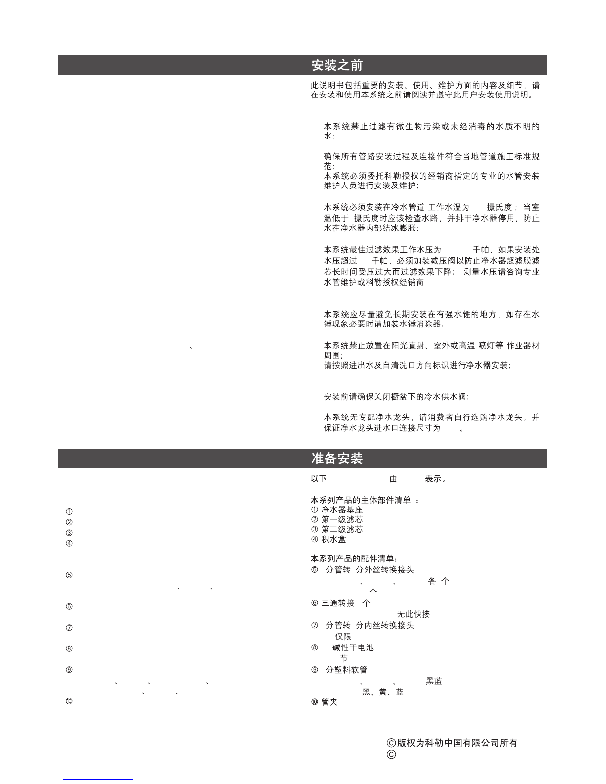
SKU K-5339T-KTXXX are shown as KTXXX.
Main parts included:
Other parts included:
Filter base
Filter cartridge Level 1
Filter cartridge Level 2
Water tray
3/8" x1/2" Male Thread Faucet Adapter
----( One for each of KT100 KT200 KT400)
----( Two for KT500)
Water supply adapter
----(K-5339T-KT500 not included)
3/8" x 1/2" Female Thread Adapter
----(only K-5339T-KT500 included)
AA alkaline dry batteries
----(3 batteries)
3/8" Plastic tubing
----(KT100 KT200 KT400: Black Blue)
----(KT500: Black Yellow Blue)
Pipe clip
·
·
·
·
·
·
·
·
·
·
( 1-38 )
1
100-400
400
(
)
()
G1/2
K-5339T-KTXXX KTXXX
34
----(KT100 KT200 KT400 1 )
----( KT500:2 )
(1 )
----(K-5339T-KT500 )
34
----( K-5339T-KT500)
AA
----(3 )
3
----(KT100 KT200 KT400 )
----(KT500 )
-1-
BEFORE YOU BEGIN
GETTING STARTED
, 2014
Copyright Kohler China Ltd., 2014
1211428-T01-A
Page 3
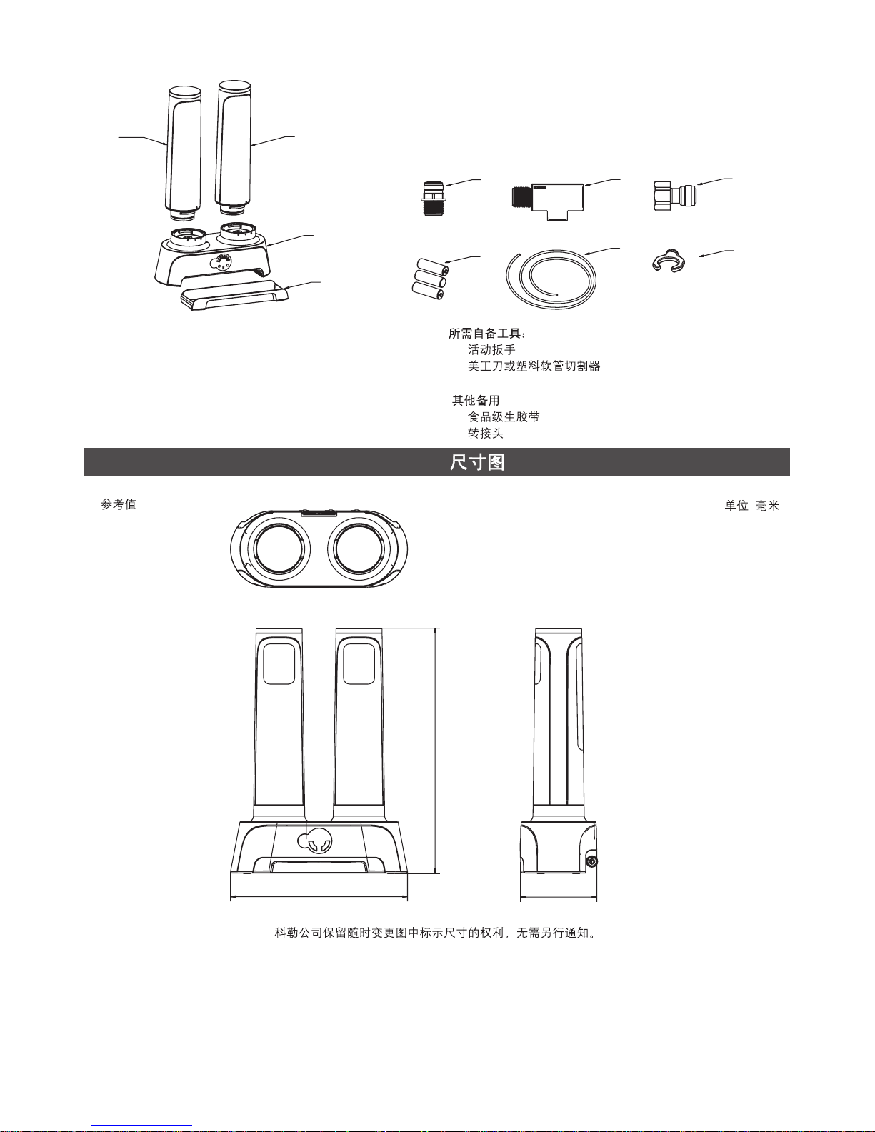
Tools required (not included)
Other Materiel (for use if necessary)
·
·
·
·
Adjustable wrench
Utility knife or tube cutter
Thread Sealant Tape
Adapter
·
·
·
·
-2-
Kohler reserves the right to change marked dimensions without prior notice.
2
3
1
4
5
8
6
9
7
10
Unit: mm
:
Reference Value
ROUGHING-IN
431
310
133
1211428-T01-A
Page 4

-3-
Step 1 Pre-install Water Filtration Faucet Refer to
Figure 1- Figure 2
Note:
Please pre-install Water filtration faucet of Kohler brand
or other brands on the sink. (Refer to Water filtration Faucet
Installation Manual for tools and detailed installation steps of
water filtration faucet. For water filtration faucet other than
Kohler brand, please make sure the inlet dimension is G1/2"
or with a 3/8" adaptor).
1. Make sure cold water supply line under the sink is turned
off;
2. Disconnect cold water line from threaded stub on bottom
of tap faucet;
3. Screw 3/8" x 1/2" Male Thread Faucet Adapter to the
female threaded Water filtration faucet stub, Hand it
tighten and snug with wrench;
4. A. (KT100 KT200 KT400): Screw the water supply
adapter - female threaded stub to the cold water supply
valve male threads as shown. Hand it tighten and snug
with wrench. Screw the female threaded tap faucet stub
to the water supply adapter;
4. B. (KT500): Screw the 3/8" x 1/2" Female Thread Adapter
- threaded stub to the cold water supply valve male
threads, Hand it tighten and snug with wrench, then
Screw 3/8" x 1/2" Male Thread Faucet Adapter to the
female threaded Tap faucet stub, Hand it tighten and
snug with wrench.
1- 2
(
G1/2" 3 )
1.
2.
3. 3 4
4. A. (KT100 KT200 KT400)
4. B. (KT500) 3 4
;3 4
INSTALLATION
Figure 1
1
Figure 2
2
Stub of Tap Faucet
Stub of Tap Faucet
Stub of Tap Faucet
Cold Water Supply Valve
Cold Water Supply Valve
Cold Water Supply Valve
Water Filtration
Faucet Stub
3/8" x 1/2"
Male Thread
Faucet Adapter
34
3/8" x 1/2"
Male Thread Faucet Adapter
34
3/8" x 1/2"
Female Thread Adapter
34
KT100, KT200, KT400 KT500
Water Supply Adapter
2
1
3
4A
4B
4A
4B
1211428-T01-A
Page 5

-4-
Step 2: Making connections
(KT100 KT200 KT400)·
According to the
corresponding colors, insert the black 3/8"
Plastic tubing into the filter inlet port and
the water supply adapter, insert the blue
3/8" Plastic tubing into the filter outlet port
and the end of the Water filtration faucet
(Figure 3);
· (KT500)According to the corresponding
colors, insert the black 3/8" Plastic tubing
into the filter inlet port and the cold water
supply valve, insert the blue 3/8" Plastic
tubing into the filter outlet port and the end
of the Water filtration faucet. insert the
yellow 3/8" Plastic tubing into the filter
Auto Clean port and the end of the Tap
water faucet ( Figure 4).
· (KT100 KT200 KT400)
3
3
(3)
· (KT500)
3
34
3
3
(4)
Figure 3
3
Figure 4
4
Tap Faucet
Tap Faucet
Cold Water Supply Valve
Cold Water Supply Valve
3/8" Plastic Tubing-Blue
3()
3/8" Plastic Tubing-Blue
3()
3/8" Plastic Tubing-Black
3()
3/8" Plastic Tubing-Black
3()
3/8" Plastic Tubing-Yellow
3()
Hot Water Supply Valve
Water Filtration Faucet
Water Filtration Faucet
3/8" x 1/2"
Male Thread Faucet Adapter
34
3/8" x 1/2"
Male Thread Faucet Adapter
34
Water Supply Adapter
3/8" x 1/2"
Female Thread Adapter
34
Hot Water Supply Valve
Note:
Note:
Cut tubing straight with a utility knife,
make sure there are no cuts, nicks, flat spots
or sharp edges as figure 5, If any of these are
present, cut the tubing again; Do not kink
tubing. ( Figure 5)
It may be difficult to release the tubing
due to water pressure when replacing service
parts. In this case, please shut off the cold
water supply valve, turn on the Water filtration
faucet to depressurize and then try to release
the tubing again.
(5)
Figure 5
5
Correct Cut
Incorrect Cut
1
2
3
1
2
3
Figure 6
6
To Attach Tubing
Push tubing in as far as it can go
Tubing must be inserted past
O-ring and hit backstop
O
Insert the clip
To Release Tubing
Pull out clip
Push in collect to release tubing.
With collect held, pull tubing straight out.
Figure 7
7
1211428-T01-A
Page 6

-5-
Step 3: Installing Filter Cartridge & Replacing Filter
Cartridges
·
·
·
Remove and discard the dustproof cap (sanitary
protective cap) from the cartridge;
Verify both O-rings are present and positioned correctly in
the grooves;
Push the filter cartridge Leve1 (blue color matching icon )
into the filter base on the left side and the filter cartridge
Leve2 (orange color matching icon ) on the right side,
align the hollow icon of the cartridge with the hollow icon
on the filter base, press the cartridge deep into the water
base, then turn cartridge clockwise until the hollow icon of
the cartridge were aligned the color filled icon on the filter
base, it will be fully installed. (Figure 8)
Step 4: Test System
NOTE:
·
·
·
Turn on the water filtration faucet;
Slowly turn on the cold water supply valve, Run water to
flush trapped air;
It is normal for there to be Residual air in the
System causing bubbles (temporary cloudiness) in the
water.
Turn off the water filtration faucet, Keep the cold water
supply valve turned on for 15 minutes. Check all fittings
and tubings for leaks. If it leaks, see Troubleshooting.
Step 5: Flush Filter
· Turn on the cold water supply valve and the water
filtration faucet, run water for a minimum of 10 minutes to
flush, The system installation is now complete and ready
to serve filtered water.
·
·
·
O
()
()
60
(8)
·
·
·
()
15
· 10
ab c
Figure 8
8
1211428-T01-A
Page 7

-6-
Step 6: Install Batteries
· Remove the back cover, install three AA batteries
according to directions for positive and negative poles, put
the cover back. (Figure 9)
Step 7: Display Confirmation
·
·
Push and hold the reset button for approximately 5
seconds until all lights are on ( ).
Repeat this action each time after filtration replacement.
So the reminder of filtration replacement could be reset.
Figure 10
·
(9)
·
·
( 10)
Figure 9
9
Figure 10
10
Warning Button
Battery Life Light
Reset Button
Filter Service Life Light
1211428-T01-A
Page 8

-7-
Performance indicator
Note:
·
·
·
The ach-shaped light bar may gradually go out as service
time runs out and water volume accumulates. When the
last bar of light flashes, please replace the filter cartridge;
When the last bar of light flashes, buzzing alarm may
sound whenever the water filtration faucet is turned on to
remind users to replace the filtration cartridge. Users can
press the warning button to stop the buzzing alarm, after
which the light will still flash to remind;
Replace batteries when battery life light flashes or each
time before replacing the filtration cartridge. (Replace
batteries at least once every year.)
Replacing batteries will not cause data loss.
However, when batteries are exhausted, the monitoring
system will stop data recording. Please replace batteries
timely!
Installing and Replacing Filtration Cartridge
· Please replace filtration cartridge when at its service cycle.
·
·
·
(
)
·
K-5339T-KT100 K-5339T-KT200 K-5339T-KT400 K-5339T-KT500
1208778
(1208811+
1208812)
1208779
(1208813+
1208814)
1208781
(1208817+
1208818)
1208782
(1208819+
1208820)
Filter
Model
Cartridge
Model
K-5339T-KT100 K-5339T-KT200 K-5339T-KT400 K-5339T-KT500
1208778
(1208811+
1208812)
1208779
(1208813+
1208814)
1208781
(1208817+
1208818)
1208782
(1208819+
1208820)
· After replacing the filter cartridge, in order to avoid
residual water storage in kitchen cabinets, small amount
of water residual will be run into the water tray. Empty the
water tray and put it back.
Please timely empty the water tray to avoid
microorganism growth.
Note:
·
EMPTY THE WATER TRAY
Important Information in Using the System:
Do not use with water that is microbiologically unsafe or of
unknown quality without adequate disinfection before or after
the system.
Before prolonged periods of non-use (such as during a
vacation) it is recommended that the cold water supply
valve be turned off. If it is more than one week, please
flush the filter thoroughly for at least 5 minutes before
reusing it;
If leaks occur and persist on system, please first turn off
the water supply valve. Call Kohler -Free Technical
Support line directly or your local distributor authorized by
Kohler;
Local water conditions and actual volume of water can
affect filter life. Be sure to replace the cartridge when
prompted by the performance LED indicator.
·
·
·
·
·
·
()
15
OPERATION INSTRUCTIONS
1211428-T01-A
Page 9

-8-
TROUBLESHOOTING GUIDE
No.
Symptom
1
2
5
6
7
4
8
Probable Cause Solution
Leaks at quick connect fittings.
No water flow from the water
filtration faucet.
Water flow from the water filtration
faucet becomes small.
All light go out.
Filtered water tastes strange or like
chlorine bleach.
Tubing is not pushed to the backstop.
Tubing is not straight and smooth.
The main water line valve is closed.
The tubing is crimped or sharp
bended.
The filtration cartridge is blocked.
Batteries is exhausted.
Service life of carbon block cartridge
runs out.
Reinsert tubing into push-in fitting as
far as it will go.
Recut tubing.
Check and open it.
Keep the tubing straight.
Replace the cartridge.
Replace the batteries.
Replace the cartridge.
3
Leaks at quick tubing.
Tubing is cracke or scratched. Simply cut that portion away and
reinsert tubing into push-in fitting.
1
2
5
6
7
4
8
3
· System tested by Kohler in accordance with NSF / ANSI
Standard 42&53 for the reduction of substances listed
below.
Cyst : Giardia Cysts or Cryptosporidium Oocysts. It is a
common infectious protozoon with diameter of about 0.5-1um.
·
NSF / ANSI
Standard 42&53
0.5-1
PERFORMANCE DATA SHEET
K-5339TKT100
K-5339TKT100
K-5339TKT200
K-5339TKT200
K-5339TKT400
K-5339TKT400
K-5339TKT500
K-5339TKT500
800 800
0.75 0.75
1000 1000
0.75 0.75
2000 2000
0.75 0.75
3500 3500
0.8 0.8
Model
Particulate
Chlorine/
Taste & odor
/
Lead
Mercury
Cyst* *
VOC
(volatile organic
compounds)
Capacity (gallon) (gallon)
Flow rate(gpm)
(gpm)
1211428-T01-A
Page 10

-9-
K-5339T-KT100
0.1-0.4MPa
1L/min
1000L
- (2001)
()
()
19
( ) (2014)
0080
K-5339T-KT200
1L/min
( ) (2014)
0080
K-5339T-KT400
1L/min
2000L
( ) (2013)
0335
K-5339T-KT500
2L/min
( ) (2013)
0336
1211428-T01-A
 Loading...